EP3121486A2 - Transmission a demultiplication harmonique et son procede de fabrication - Google Patents
Transmission a demultiplication harmonique et son procede de fabrication Download PDFInfo
- Publication number
- EP3121486A2 EP3121486A2 EP16181097.3A EP16181097A EP3121486A2 EP 3121486 A2 EP3121486 A2 EP 3121486A2 EP 16181097 A EP16181097 A EP 16181097A EP 3121486 A2 EP3121486 A2 EP 3121486A2
- Authority
- EP
- European Patent Office
- Prior art keywords
- ring gear
- circumferential
- projection
- gear
- press
- Prior art date
- Legal status (The legal status is an assumption and is not a legal conclusion. Google has not performed a legal analysis and makes no representation as to the accuracy of the status listed.)
- Pending
Links
Images






Classifications
-
- F—MECHANICAL ENGINEERING; LIGHTING; HEATING; WEAPONS; BLASTING
- F16—ENGINEERING ELEMENTS AND UNITS; GENERAL MEASURES FOR PRODUCING AND MAINTAINING EFFECTIVE FUNCTIONING OF MACHINES OR INSTALLATIONS; THERMAL INSULATION IN GENERAL
- F16H—GEARING
- F16H49/00—Other gearings
- F16H49/001—Wave gearings, e.g. harmonic drive transmissions
-
- F—MECHANICAL ENGINEERING; LIGHTING; HEATING; WEAPONS; BLASTING
- F16—ENGINEERING ELEMENTS AND UNITS; GENERAL MEASURES FOR PRODUCING AND MAINTAINING EFFECTIVE FUNCTIONING OF MACHINES OR INSTALLATIONS; THERMAL INSULATION IN GENERAL
- F16H—GEARING
- F16H57/00—General details of gearing
- F16H57/02—Gearboxes; Mounting gearing therein
- F16H57/023—Mounting or installation of gears or shafts in the gearboxes, e.g. methods or means for assembly
Definitions
- the invention relates to a method for producing a stress wave transmission.
- the invention also relates to a voltage wave transmission having a shaft generator, an externally toothed flexspline and an internally toothed ring gear, the internal toothing of which meshes with the external toothing of the flexspline, and a transmission housing.
- the invention also relates to an actuator, in particular Fahrwerksaktuator, and a support structure with such a gear or actuator.
- the invention also relates to a chassis and a motor vehicle with such a transmission or actuator.
- Transmissions of the type mentioned are often used for the production of active stabilization systems, in particular for improving the lateral tilt and roll behavior when cornering and / or to avoid or reduce pitching movements when starting or braking, are used in various embodiments.
- an actively controlled actuator is arranged, which, depending on the driving situation, the stabilizer bar halves rotated against each other to counteract a lateral inclination of the vehicle.
- the swivel motor for roll control by mutually rotating two motor vehicle stabilizers known.
- the swivel motor consists of at least one adjusting drive with an electric motor, a swivel motor gear and a housing.
- the swivel motor is arranged between the motor vehicle stabilizers, which can also be regarded as halves of an overall stabilizer, and is intended, on the basis of a suitable control, to turn these stabilizer halves as required against each other.
- Out DE 10 2006 040 109 A1 is an active, shared motor vehicle stabilizer with built-in swivel motor known.
- the motor vehicle stabilizer is used for roll control and has an adjusting drive with a motor, a transmission and a housing.
- a sensor for detecting the torsion angle of the stabilizer part is mounted, the encoder is fixed to the stabilizer part or vice versa.
- Out DE 10 2008 048 950 A1 is a pressure medium actuated swing motor for a vehicle known, which is arranged in a split stabilizer and with which the two stabilizer halves to compensate for vehicle movements are mutually pivotable.
- the swivel motor has a piston which is axially displaceable in a housing and work spaces arranged on both sides of the piston. By pressurizing the work spaces in conjunction with one or more coupling elements, a torque between the stabilizer halves can be generated.
- There is a connection between the working spaces which can be closed or released by means of a valve depending on the driving condition of the vehicle.
- Out DE 10 2009 013 053 A1 is a stabilizer for a chassis of a motor vehicle with at least two stabilizer elements known, which are rotatable by means of at least one electromotive actuator for roll control and which are each connected via at least one coupling rod to the chassis.
- the stabilizer can be decoupled by means of at least one hydraulic unlocking device.
- Out EP 2 011 674 A1 is a stabilizer assembly comprising a two-part stabilizer, the stabilizer sections perform a rotational relative movement to each other and exert a restoring force at an opposing torsional load known.
- the restoring force is adjustable by means of an actuator in conjunction with a transmission, wherein the stabilizer assembly, regardless of a Torsionsfeder Ober the stabilizer sections has at least one further spring which causes a Torsionsfeder Ober.
- A1 is a roll stabilizer for a motor vehicle with a first and a second stabilizer part, which are each assigned to a wheel of a common vehicle transverse axis of the motor vehicle and / or associated known.
- the roll stabilizer has a housing which is designed for a motor vehicle-fixed mounting and in which the two stabilizer parts are mounted for carrying out the same direction and opposite directions pivoting movements.
- an actuator device is provided, which comprises an electric motor and a transmission gear, wherein the electric motor for generating a torque and the transmission gear to continue the torque to the stabilizer parts are formed and / or arranged, and wherein the electric motor of the
- a low weight bearing and a wave gear assembly are known.
- An outer or an inner bearing ring of the bearing has fixing holes to allow attachment of the ring to another element.
- the parts of the bearing on which raceway surfaces are formed are made of an iron-based material, while the main bearing ring member is made of a light material lighter than the iron-based material. Surface areas forming locating pins for fixing bolts are plated to increase the strength of these areas.
- the shaft gear device includes a rigid internal gear, a flexible external gear disposed inside the internal gear, and a shaft generator disposed inside the external gear. The internal gear and the external gear are coupled by the low-weight bearing so as to allow rotational movement of the gears relative to each other.
- a method of manufacturing a rigid internal gear of a wave gear is known.
- a rigid internal gear of the shaft gear device is formed by combining a toothing-forming ring formed with an internal gear and a gear main ring into a single body.
- the gearing forming ring is made of an iron or copper material with higher strength and abrasion resistance, while the main gear ring made of a lightweight material such.
- As an aluminum alloy is produced.
- the outer peripheral surface of the gear forming ring is aluminized to form an aluminum-dispersed coating before a flow forming operation is performed on the gear-forming ring in the main gear ring to communicate with each other through the main gear ring and the gear-forming ring unite.
- a voltage wave transmission of the type mentioned which is characterized in that the internally toothed ring gear is pressed in a receiving area for the ring gear in the transmission housing and thereby rotatably held relative to the transmission housing, wherein in a cross-sectional plane through the receiving area, the radial dimension the gear housing wall is smaller than the rim height of the ring gear.
- the invention has the very special advantage that both the gear housing, as well as the ring gear, which may be, for example, a Circularspline or a Flexspline, can be made very thin-walled. This in particular because neither the ring gear, nor the gear housing needs to have additional projections, flanges, fasteners or the like in order to fix the ring gear rotatably in the gear housing, for example by tightening or welding.
- the internally toothed ring gear is rotationally fixed relative to its rotational center of symmetry axis held in the gear housing.
- both the ring gear, and the gear housing can be made very thin-walled, is particularly a lot of space available to provide the internal teeth of the ring gear with a large pitch diameter.
- a large pitch diameter of the internal toothing is of particular advantage because a high load capacity can be achieved in order to transmit as large torques as possible via the stress wave transmission can.
- the radial dimension of the gear housing wall is smaller than the rim height of the ring gear, a compact and space-saving design is advantageously achieved in terms of the outer dimensions, while still transmitting large torques compared to conventional voltage shaft gears same outer radial extent can be.
- the quotient of the radial dimension of the gear housing wall and the rim height of the ring gear is smaller than 0.8, in particular smaller than 0.5.
- the radial dimension of the gear housing wall is understood to mean the difference between the inner radius and the outer radius of the gear housing wall in the region of the cross-sectional plane.
- the radial dimension of the transmission housing wall varies axially and / or more tangentially in the region of the receptacle, for example because the transmission housing wall has an inwardly directed press-in toothing or a step
- the smallest radial distance from the inner surface to the outer surface of the gear housing wall is the radial distance of the transmission housing wall Transmission housing wall understood. This can be, in particular, the radial distance from the root diameter of the press-in toothing to the gear housing wall.
- the radial dimension of the transmission housing wall means the smallest radial distance from the inner surface to the outer surface of the transmission housing wall
- recesses and / or clearances such as radial holes of small diameter, disregarded, which weaken the gearbox not or only insignificantly.
- Such recesses and / or clearances may in particular be those whose diameter is more than 10 times, in particular more than 20 times, smaller than the inner diameter, in particular the average inner diameter, of the transmission housing wall.
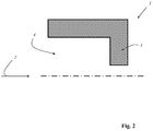
- the ring height of the ring gear is understood to be the difference between the inner radius and the outer radius of the ring gear in the region of the cross-sectional plane. If the wreath height in the area
- the recording in the axial direction and / or varies in tangential, for example, because the ring gear has an outwardly directed press-in teeth or a gradation, is understood by the rim height of the smallest radial distance from the inner surface to the outer surface of the ring gear. This can be, in particular, the radial distance from the root diameter of the press-in toothing to the root diameter of the external toothing.
- the ring gear is fixed non-rotatably in the gear housing exclusively by the press-fitting operation, without an additional fastening of the ring gear, for example by producing a material connection, for example by soldering, welding or gluing, or an additional other connection, such as by screwing done.
- a material connection for example by soldering, welding or gluing
- an additional other connection such as by screwing done.
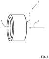
- the gear housing is preferably cylindrical, at least in the region of a receptacle for the ring gear.
- at least the receptacle of the gear housing for the ring gear is conical or stepped.
- the ring gear is pressed in the axial direction in a cylindrical receptacle of the gear housing, wherein the inner diameter of the gear housing in the region of the receptacle is smaller than an outer diameter of the ring gear to be pressed.
- the gear housing has an axial stop, upon reaching the press-in process is terminated.
- the outer peripheral side of the ring gear to be pressed in is designed in such a way that the ring gear to be pressed in is centered automatically at the beginning of the press-in operation relative to the housing of the gear housing.
- the outer side of the ring gear in particular a first circumferential projection of the ring gear, which is oriented in the pressing-in direction, be formed conical or cylindrical.
- the outer peripheral side of the ring gear has at least one tangentially encircling projection.
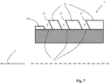
- the outer peripheral side of the ring gear to be pressed in has a plurality of tangentially encircling, axially spaced-apart projections.
- the projections may all have the same outer diameter.
- the tangentially encircling projections have different outer diameters, it being particularly advantageous for the outer diameters of the encircling projections to decrease in the press-in direction. In this way, a stepped conicity can be achieved, which facilitates the press-in process and which moreover makes it possible to provide a plurality of projections, in particular all projections, effectively with a cutting edge aligned in the pressing-in direction.
- At least one circumferential projection has a cutting edge aligned in the pressing-in direction.
- the cutting edge is preferably designed such that material is peeled or scraped off from the inside of the transmission housing during the press-fitting process. In this way, a particularly accurate fit of the ring gear is achieved in the transmission housing.
- the rake angle may be positive to remove material from the inside of the transmission housing. However, it may also be provided that the rake angle is negative in order to achieve scraping.
- the cutting angle of the cutting edge is less than 90 degrees, which can be achieved, for example, that the oriented in the press-fitting direction end of the projection, for example, during a turning process, is conical.
- a groove can be rotated in the outer peripheral surface of the ring gear, wherein the feed direction during rotation has an angle different from zero degrees to the radial direction.
- the outer peripheral surface of the ring gear is formed conically. This can also be done, for example, in a turning process or by milling over the pre-turned ring gear.
- a plurality of circumferential projections in particular a plurality of circumferential projections with different outer diameters, each have a cutting edge oriented in the pressing-in direction.
- the cutting edges in particular due to the different outer diameter of the projections, are radially spaced from each other.
- the removal of material takes place within the gear housing during the pressing process gradually.
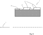
- the outer circumferential surface of the ring gear to be pressed has a plurality of circumferential projections with outer diameters decreasing in the press-in direction, wherein only the projection with the largest outer diameter has a cutting edge aligned in the press-fit direction.
- Such an embodiment has the effect that the projections with the smaller outer diameters first center the ring gear during the press-in operation, before a material removal takes place through the cutting edge of the projection with the largest outer diameter. Therefore, such a design has the particular advantage that the ring gear is positioned and fastened particularly accurately in the transmission housing.
- the circumferential projection consists in such an embodiment of a plurality of teeth, which may in particular have a tip or an axially extending vertex edge.
- the teeth are flattened circumferentially or rounded.
- the appropriate tooth shape can be selected.
- pointed teeth or teeth with an axially extending vertex edge have the particular advantage that a particularly high resistance to rotation of the ring gear is achieved relative to the transmission housing.
- teeth with rounded tooth tips have the particular advantage of a lower notch effect in the transmission housing.
- the axially extending notches may be square, in particular V-shaped or cup-shaped in radial cross-section. However, it is also possible that the axially extending notches are formed rounded in radial cross-section.
- the axially extending notches can be made in particular by milling or by impact or by skiving.
- the tangential circumferential projections are first generated and then the axially extending notches incorporated.
- the procedure is reversed.
- the ring gear and the housing of the gear housing of the type are dimensioned such that only the teeth present on the outer circumferential surface of the ring gear cut into the material of the gear housing. In this way, a rotationally secure attachment of Ring gear achieved with low material load on the gear housing.
- the root diameter of the toothing on the outer peripheral surface of the ring gear is smaller than the diameter of the receptacle for the ring gear.
- the head revolved diameter of the toothing on the outer peripheral surface of the ring gear is greater than the diameter of the receptacle for the ring gear.
- the ring gear has a radial wall thickness which is 4 to 10 times, in particular 5 to 7 times greater than the tooth height of its internal toothing.
- the ring gear has a radial wall thickness in the range of 5 to 20 times, in particular in the range of 8 to 15 times, in particular in the range of 10 to 12 times, the Tooth height of the teeth of the outer peripheral surface, in particular the teeth of a circumferential projection of the outer peripheral surface is located.
- Such designs are particularly compact and yet provide sufficient rigidity of the ring gear.
- a circumferential projection of the ring gear to be pressed on a plurality of teeth wherein each tooth has a varying over the tooth width tooth height.
- the tooth height initially increases over the tooth width and then drops again. It is also possible that the tooth height, in particular in the press-fitting direction, decreases linearly over the tooth width or decreases following another curve shape. Such a design facilitates the press-in process and allows a particularly accurate centering and positioning of the ring gear in the transmission housing.
- the individual teeth have a change over the tooth width nach Vietnamese bemesser.
- the root diameter decreases in the pressing-in direction.
- the outer peripheral surface of the ring gear to be pressed in has a plurality of circumferential projections with outer diameters decreasing in the press-in direction, wherein only the projection with the largest outer diameter has a multiplicity of teeth, in particular pointed teeth.
- the ring gear is initially centered coaxially to receive the gear housing during the press-fitting process by the projections with the smaller outer diameters. As the pressing-in process progresses, in particular by pressing in the toothed projection with the largest external diameter, a torsional security of the ring gear relative to the gearbox is produced.
- the outer peripheral side of the ring gear to be pressed on at least one tangentially encircling groove.
- the groove may in particular be produced by a turning process.
- By screwing in one or more grooves in particular the above-mentioned circumferential projections can be produced. This may be provided in particular that a groove is not screwed purely in the radial direction, but rather slightly tilted to the radial direction, for example, to produce at the adjacent projection a cutting edge with a cutting angle less than 90 degrees.
- the ring gear to be pressed in can have several, in particular several, different width, circumferential grooves.
- the groove is designed and arranged such that it automatically picks up chips separated from the transmission housing during the press-fitting process.
- a design has the particular advantage that the separated chips do not hinder the press-in process and in particular the exact positioning of the ring gear within the transmission housing.
- the radial dimension of the gear housing wall is smaller than the rim height of the ring gear - is pressed before pressing adhesive in a tangential direction, the cutting projection filled in front of the groove.
- the adhesive forms an additional connection between the CS ring and the gear housing after the pressing process.
- the adhesive is filled in a circumferential in the tangential direction, the cutting projection upstream groove, there is not only a thin adhesive layer. Rather, such a relatively large amount of adhesive is accumulated, so that it can absorb larger strains, as they can occur, for example, in temperature fluctuations when the internally toothed ring gear is pressed into a transmission component, which has a different, in particular larger, coefficient of thermal expansion than that ring gear. In this way it can be ensured that the ring gear does not detach from the transmission component even with a temperature change, in particular during heating.
- the groove is formed and arranged that it automatically picks up chips separated from the transmission component by means of the cutting edge during insertion. It is particularly advantageous in such an embodiment that the chips separated during a press-in operation by means of the cutting edge of the transmission component, which may be in particular a transmission housing, mix with the charged adhesive, so that the cured adhesive is stabilized particularly well as a result ,
- the adhesive may be filled over the entire circumference of the groove.
- the groove is completely filled with adhesive.
- the adhesive can be liquid during filling, which allows easy filling.
- the adhesive may be a one-component adhesive. Alternatively, it is also possible that the adhesive is a two-component adhesive. In particular, the adhesive may include epoxy resin.
- an adhesive can be used which cures at a temperature in the range of 15 to 25 degrees Celsius, in particular at room temperature.
- the adhesive cures at a temperature above 25 degrees Celsius, in particular above room temperature, and that the transmission component is heated after being pressed.
- the adhesive is exposed to UV light for curing.
- a friction-increasing material is applied prior to pressing on the outside of the internally toothed ring gear and that the ring gear is rotated about the axial direction after being pressed in relative to the transmission component.
- the inside of the receptacle and the outside of the internally toothed ring gear are circular-cylindrical.
- the outside of the internally toothed ring gear is tooth-free and / or free of tangential circumferential projections, in particular also of projections are incorporated in the notches formed.
- the outer side of the internally toothed ring gear can be smooth.
- the inside of the receptacle and the outside of the ring gear may have a surface roughness in the range of 3.6 microns to 25 microns.
- an interference fit is produced by the pressing.
- the press fit Before the ring gear is rotated relative to the transmission component, which may in particular be a transmission housing, the press fit already ensures that a certain torque can be transmitted from the ring gear to the transmission component.
- the connection of the friction-increasing material is increased to the ring gear and to the transmission component, so that in the result an increased torque can be transmitted.
- the ring gear is formed and positioned within the gear housing so that it acts as an axial securing and / or as a support for a bearing, in particular a roller bearing of the stress wave transmission and / or for a bearing plate.
- the ring gear has a radially inwardly directed projection which serves as an axial securing device for a shaft generator bearing.
- the shaft generator bearing is preferably a radially flexible bearing, by means of which the drive core of the shaft generator is rotatably mounted in the radially flexible flexspline.
- the ring gear serves as a support for a bearing for rotatably supporting the shaft generator within the gear housing and / or has a bearing plate for a rolling bearing for rotatably supporting the shaft generator within the gear housing.
- the ring gear is designed and arranged such that it acts as a support for a bearing plate.
- a bearing plate in particular axially, is clamped during the press-fitting process between the gear housing and the ring gear and is thus fastened within the gear housing.
- the radial dimension of the gear housing wall is smaller than the rim height of the ring gear - an internally toothed ring gear, on its outside at least one in Tangentialraum circumferential cutting projection with a cutting edge formed to intersect the gear member in a press-fitting operation and having at least one tangential clamping protrusion which has no cutting edge and which is axially spaced from the cutting protrusion and which is downstream of the cutting protrusion in the press-fitting direction; having a larger outer diameter than the cutting projection.
- Such a internally toothed ring gear has the very special advantage that it can be anchored particularly securely by a press-fit. This is especially true when the internally toothed ring gear is pressed into a transmission component, which has a different, in particular larger, coefficient of thermal expansion, as the ring gear.
- the tangential circumferential clamping projection spaced from the cutting projection and downstream of the cutting projection and having a larger outer diameter than the cutting projection may exert a higher radially outwardly directed clamping force than the cutting projection.
- the excess of the clamping projection relative to the inner diameter of the receptacle is greater than that due to an expected temperature change resulting change in the difference between the diameter of recording and ring gear. In this way it can be ensured that the ring gear does not detach from the transmission component even with a temperature change, in particular during heating.
- the cutting projection has a diameter at the location of the cutting edge which is larger by a percentage value from the range of 0.001% to 0.1%, in particular 0.01%, than the internal diameter of the receptacle, and / or that the clamping projection has an outer diameter which is greater by a percentage value in the range of 0.01% to 1%, in particular of 0.1%, than the inner diameter of the receptacle. It is alternatively or additionally advantageously also possible that the clamping projection on the cutting projection facing side has an outer diameter which is greater by a percentage value from the range of 0.01% to 1%, in particular by 0.1% the inner diameter of the recording.
- the cutting projection at the location of the cutting edge has a diameter which is larger by an excess in the range of 0.01 mm to 1 mm, than the inner diameter of the receptacle.
- the clamping projection at the location of the cutting edge has a diameter which is greater by an excess in the range of 0.1 mm to 1 mm, than the inner diameter of the receptacle. This in particular if the ring gear has a diameter in the range of 100 mm to 110 mm, in particular of 104 mm.
- the transmission component which may in particular be a transmission housing or a gear ring, is preferably cylindrical, in particular circular-cylindrical, at least in the region of a receptacle for the ring gear.
- a receptacle for the ring gear is conical or stepped.
- the ring gear is pressed in the axial direction in a cylindrical, in particular circular cylindrical, receiving the transmission component.
- the transmission component may advantageously have an axial stop, when it reaches the pressing-in process is terminated.
- the ring gear is circular cylindrical and / or rotationally symmetrical.
- the clamping projection on a run-up slope and / or decreasing in the press-fitting outer diameter may advantageously have an angle in the range of 5 degrees to 15 degrees to the axial direction.
- the cutting projection and / or the clamping projection may each have a plurality of teeth.
- Such a design has the particular advantage that material of the transmission component can push into the notches, which particularly increases the torsional strength.
- the cutting projection has a plurality of teeth, wherein each tooth has a varying over the tooth width tooth height, and / or that the clamping projection has a plurality of teeth, each tooth has a tooth width over the varying tooth height having.
- the ring gear on the front side and in the press-in direction upstream of the cutting projection on a circumferential tangential Ein Wennvorsprung, which has no cutting edge and the outer diameter is equal to or smaller than the opening diameter of the recording.
- the insertion projection has a plurality of teeth, wherein each tooth has a varying over the tooth width tooth height.
- a respective groove is present between successive projections in the press-in direction.
- the insertion projection and the cutting projection are separated from one another by a groove extending in the tangential direction.
- the cutting projection in the press-in direction is preceded by a groove such that it automatically absorbs chips separated from the gear component by the cutting edge when being pressed in.
- Also between the cutting projection and the clamping projection can advantageously be present in a circumferential tangential groove.
- the internal toothing is pressed radially inward after pressing by the radial clamping forces of the receptacle that change the shape and / or the dimensions of the internal toothing.
- this is taken into account in the manufacture of the internally toothed ring gear.
- the shape and / or the dimensions can be kept such that, after being pressed into the receptacle, they have a predetermined nominal dimension and / or a predetermined desired shape. It is also possible that dimensional deviations are corrected after being pressed in.
- the invention has the very special advantage that the gear housing and the ring gear can be made of different materials, in particular of materials with different mechanical properties.
- the gear housing made of light metal, in particular made of aluminum or an aluminum alloy, while the ring gear is made for example of steel.
- Such a combination of materials has the particular advantage that the stress wave transmission as a whole can be made particularly easy, while at the same time no compromises have to be made with respect to the endurance and operability.
- an actuator in particular a Fahrwerksaktuator, which includes a drive motor and a voltage wave transmission according to the invention.
- the drive motor is coupled by means of a traction mechanism to the voltage wave transmission.
- the drive motor is coupled in a particular embodiment by means of a belt drive to the stress wave transmission.
- an active chassis for a motor vehicle which includes such an actuator and / or a voltage wave transmission according to the invention.
- the actuator by means of the actuator, the two rotatably mounted stabilizer halves of a vehicle axle, in particular driving situation-dependent, are rotated against each other.
- radselektiv for each wheel of the motor vehicle a separate actuator is provided so that the compression and rebound of each wheel is independent of the other wheels adjustable.
- a roll stabilizer but also a pitch stabilizer can be realized.
- exactly one such actuator can be provided per vehicle axle.
- the active chassis is controlled to tilt the vehicle body around the vehicle longitudinal axis when cornering to reduce the effect of centrifugal forces on the vehicle passengers.
- the support structure may be a vehicle component or a part of a vehicle component.
- the support structure is formed as part of a, in particular active, chassis.
- the support structure may advantageously be formed as part of a vehicle axle, namely in particular as a cross-beam.
- the support structure has a crossbeam, in particular a crossbeam of a chassis, which forms the transmission housing or at least part of the transmission housing.
- the cross-beam forms a part of the transmission housing at least in the receiving area for the ring gear.
- such a crossbeam advantageously perform a Mehrfachfunkton, namely on the one hand its original function as a chassis component and on the other hand as a housing for a voltage wave transmission, the voltage wave transmission as part of an active Fahrtechniksaktuators can also advantageously be part of the chassis.
- the support structure is formed as a box-shaped cross member of a vehicle axle, wherein in the space enclosed by the cross member space the voltage wave transmission according to the invention and / or the above-mentioned actuator are arranged.
- electronic components for controlling and / or regulating the actuator can also be arranged in the cavity.
- the stress wave transmission and / or the actuator and / or the electronic components are particularly well protected against contamination and damage.
- the stabilizer bars in particular a split stabilizer, can extend to the actuator and be coupled thereto.
- a robot which has a voltage wave transmission according to the invention or an actuator with such a voltage wave transmission.
- a motorized joint for connecting two relatively movable supports of a programmable automatic movement machine having a voltage wave transmission according to the invention and / or an actuator with such a voltage wave transmission.
- a housing of the programmable motion machine has the receptacle for the internally toothed ring gear and / or that a housing of the programmable motion machine forms the transmission component, which has the receptacle for the internally toothed ring gear.
Landscapes
- Engineering & Computer Science (AREA)
- General Engineering & Computer Science (AREA)
- Mechanical Engineering (AREA)
- Gears, Cams (AREA)
Applications Claiming Priority (1)
| Application Number | Priority Date | Filing Date | Title |
|---|---|---|---|
| DE102015112032.1A DE102015112032B4 (de) | 2014-07-23 | 2015-07-23 | Spannungswellengetriebe und Verfahren zum Herstellen eines Spannungswellengetriebes |
Publications (2)
| Publication Number | Publication Date |
|---|---|
| EP3121486A2 true EP3121486A2 (fr) | 2017-01-25 |
| EP3121486A3 EP3121486A3 (fr) | 2017-02-15 |
Family
ID=56787248
Family Applications (1)
| Application Number | Title | Priority Date | Filing Date |
|---|---|---|---|
| EP16181097.3A Pending EP3121486A3 (fr) | 2015-07-23 | 2016-07-25 | Transmission a demultiplication harmonique et son procede de fabrication |
Country Status (1)
| Country | Link |
|---|---|
| EP (1) | EP3121486A3 (fr) |
Cited By (2)
| Publication number | Priority date | Publication date | Assignee | Title |
|---|---|---|---|---|
| CN114857244A (zh) * | 2022-05-27 | 2022-08-05 | 南京南高齿新能源汽车传动设备有限公司 | 齿轮箱装配工艺和齿轮箱 |
| US12456896B2 (en) * | 2022-05-27 | 2025-10-28 | Schaeffler Technologies AG & Co. KG | Gearbox |
Citations (9)
| Publication number | Priority date | Publication date | Assignee | Title |
|---|---|---|---|---|
| DE10215569A1 (de) | 2001-04-09 | 2003-01-30 | Harmonic Drive Systems | Verfahren zum Herstellen eines starren innenverzahnten Zahnrads einer Wellengetriebevorrichtung |
| DE10222696A1 (de) | 2001-05-22 | 2003-02-20 | Harmonic Drive Systems | Lager mit geringem Gewicht und Wellengetriebevorrichtung |
| DE102005031036A1 (de) | 2005-07-02 | 2007-01-25 | Bayerische Motoren Werke Ag | Schwenkmotor für einen geteilten Kraftfahrzeugstabilisator |
| DE102006040109A1 (de) | 2006-08-26 | 2008-02-28 | Bayerische Motoren Werke Ag | Aktiver, geteilter Kraftfahrzeugstabilisator mit eingebauten Schwenkmotor |
| DE102008010131A1 (de) | 2007-04-21 | 2008-10-23 | Schaeffler Kg | Wankstabilisator für ein Kraftfahrzeug sowie Gehäuse für den Wankstabilisator |
| EP2011674A1 (fr) | 2007-07-04 | 2009-01-07 | ZF Friedrichshafen AG | Agencement de stabilisateur |
| DE102008048950A1 (de) | 2007-09-27 | 2009-04-16 | Asturia Automotive Systems Ag | Druckmittelbetätigbarer Schwenkmotor |
| DE102009013053A1 (de) | 2009-03-16 | 2009-11-19 | Daimler Ag | Stabilisator sowie Verfahren zum Betreiben eines Stabilisators |
| DE102009006385A1 (de) | 2009-01-28 | 2010-07-29 | Schaeffler Technologies Gmbh & Co. Kg | Getriebemotor für einen Wankstabilisator |
Family Cites Families (2)
| Publication number | Priority date | Publication date | Assignee | Title |
|---|---|---|---|---|
| SE459517B (sv) * | 1987-10-09 | 1989-07-10 | Maskinteknik Foersaeljnings Ol | Anordning foer hoppassning av detaljer |
| JP4645086B2 (ja) * | 2004-07-20 | 2011-03-09 | 株式会社ジェイテクト | 波動歯車装置、伝達比可変装置、及び波動歯車装置の製造方法 |
-
2016
- 2016-07-25 EP EP16181097.3A patent/EP3121486A3/fr active Pending
Patent Citations (9)
| Publication number | Priority date | Publication date | Assignee | Title |
|---|---|---|---|---|
| DE10215569A1 (de) | 2001-04-09 | 2003-01-30 | Harmonic Drive Systems | Verfahren zum Herstellen eines starren innenverzahnten Zahnrads einer Wellengetriebevorrichtung |
| DE10222696A1 (de) | 2001-05-22 | 2003-02-20 | Harmonic Drive Systems | Lager mit geringem Gewicht und Wellengetriebevorrichtung |
| DE102005031036A1 (de) | 2005-07-02 | 2007-01-25 | Bayerische Motoren Werke Ag | Schwenkmotor für einen geteilten Kraftfahrzeugstabilisator |
| DE102006040109A1 (de) | 2006-08-26 | 2008-02-28 | Bayerische Motoren Werke Ag | Aktiver, geteilter Kraftfahrzeugstabilisator mit eingebauten Schwenkmotor |
| DE102008010131A1 (de) | 2007-04-21 | 2008-10-23 | Schaeffler Kg | Wankstabilisator für ein Kraftfahrzeug sowie Gehäuse für den Wankstabilisator |
| EP2011674A1 (fr) | 2007-07-04 | 2009-01-07 | ZF Friedrichshafen AG | Agencement de stabilisateur |
| DE102008048950A1 (de) | 2007-09-27 | 2009-04-16 | Asturia Automotive Systems Ag | Druckmittelbetätigbarer Schwenkmotor |
| DE102009006385A1 (de) | 2009-01-28 | 2010-07-29 | Schaeffler Technologies Gmbh & Co. Kg | Getriebemotor für einen Wankstabilisator |
| DE102009013053A1 (de) | 2009-03-16 | 2009-11-19 | Daimler Ag | Stabilisator sowie Verfahren zum Betreiben eines Stabilisators |
Cited By (2)
| Publication number | Priority date | Publication date | Assignee | Title |
|---|---|---|---|---|
| CN114857244A (zh) * | 2022-05-27 | 2022-08-05 | 南京南高齿新能源汽车传动设备有限公司 | 齿轮箱装配工艺和齿轮箱 |
| US12456896B2 (en) * | 2022-05-27 | 2025-10-28 | Schaeffler Technologies AG & Co. KG | Gearbox |
Also Published As
| Publication number | Publication date |
|---|---|
| EP3121486A3 (fr) | 2017-02-15 |
Similar Documents
| Publication | Publication Date | Title |
|---|---|---|
| DE102005054283B4 (de) | Radnaben-Drehgelenk-Anordnung mit Stirnverzahnung | |
| DE69304025T2 (de) | Antriebswellenanordnung | |
| DE60206229T2 (de) | Zweiteilige Achswelle | |
| EP2106356B1 (fr) | Dispositif de palier pour le montage en rotation decouple en oscillation d'un arbre intermediaire sur le bloc-moteur d'un vehicule a moteur et procede pour le montage en rotation decouple en oscillation d'un arbre intermediaire sur le bloc-moteur d'un vehicule | |
| DE60117098T2 (de) | Vorrichtung für Antriebsrad eines Motorfahrzeuges | |
| DE19512195A1 (de) | Verbindungsanordnung für ein Achsrohr mit einem Rohrjoch einer steuerbaren Antriebsachse | |
| DE10220372B4 (de) | Mehreckige Grenzfläche zwischen antreibenden und angetriebenen Komponenten | |
| DE19820206A1 (de) | Ausgleichsgehäuse für ein Ausgleichsgetriebe | |
| DE102017206551A1 (de) | Verstellantrieb für eine Lenksäule, Antriebseinheit für einen Verstellantrieb, motorisch verstellbare Lenksäule für ein Kraftfahrzeug und Verfahren zur Herstellung eines Verstellantriebs für eine Lenksäule | |
| DE102016113687A1 (de) | Innenverzahntes Hohlrad für ein Spannungswellengetriebe | |
| DE69826787T2 (de) | Kardanwelle | |
| DE10336958A1 (de) | Differentialgehäusebaugruppe | |
| DE102004008538B4 (de) | Differential mit einer Bolzenbefestigungsbaugruppe | |
| DE2036006C2 (de) | Wechselgetriebe insbesondere für Kraftfahrzeuge | |
| EP1902224B1 (fr) | Assemblage arbre-moyeu ayant un cone reel | |
| EP2632741B1 (fr) | Système d'essieu | |
| EP3121486A2 (fr) | Transmission a demultiplication harmonique et son procede de fabrication | |
| EP2359029B1 (fr) | Transmission | |
| DE4302726A1 (en) | Toothed shaft connection between drive shaft and hub - has teeth and tooth gaps in drive shaft gearing prismatic and hardened over entire length | |
| WO2022233513A1 (fr) | Liaison à trois points | |
| EP3814656B1 (fr) | Dispositif d'actionnement d'un stabilisateur de roulis réglable d'un véhicule automobile | |
| DE102014110382B4 (de) | Spannungswellengetriebe und Verfahren zum Herstellen eines Spannungswellengetriebes | |
| DE102015112032B4 (de) | Spannungswellengetriebe und Verfahren zum Herstellen eines Spannungswellengetriebes | |
| DE102014109492A1 (de) | Getriebe, insbesondere für einen Fahrwerksaktuator | |
| WO2017080794A1 (fr) | Système de roulement de roue et procédé de montage d'un système de roulement de roue |
Legal Events
| Date | Code | Title | Description |
|---|---|---|---|
| PUAI | Public reference made under article 153(3) epc to a published international application that has entered the european phase |
Free format text: ORIGINAL CODE: 0009012 |
|
| STAA | Information on the status of an ep patent application or granted ep patent |
Free format text: STATUS: THE APPLICATION HAS BEEN PUBLISHED |
|
| PUAL | Search report despatched |
Free format text: ORIGINAL CODE: 0009013 |
|
| AK | Designated contracting states |
Kind code of ref document: A2 Designated state(s): AL AT BE BG CH CY CZ DE DK EE ES FI FR GB GR HR HU IE IS IT LI LT LU LV MC MK MT NL NO PL PT RO RS SE SI SK SM TR |
|
| AX | Request for extension of the european patent |
Extension state: BA ME |
|
| AK | Designated contracting states |
Kind code of ref document: A3 Designated state(s): AL AT BE BG CH CY CZ DE DK EE ES FI FR GB GR HR HU IE IS IT LI LT LU LV MC MK MT NL NO PL PT RO RS SE SI SK SM TR |
|
| AX | Request for extension of the european patent |
Extension state: BA ME |
|
| RIC1 | Information provided on ipc code assigned before grant |
Ipc: F16H 49/00 20060101ALI20170112BHEP Ipc: F16H 57/023 20120101AFI20170112BHEP |
|
| STAA | Information on the status of an ep patent application or granted ep patent |
Free format text: STATUS: REQUEST FOR EXAMINATION WAS MADE |
|
| 17P | Request for examination filed |
Effective date: 20170809 |
|
| RBV | Designated contracting states (corrected) |
Designated state(s): AL AT BE BG CH CY CZ DE DK EE ES FI FR GB GR HR HU IE IS IT LI LT LU LV MC MK MT NL NO PL PT RO RS SE SI SK SM TR |
|
| STAA | Information on the status of an ep patent application or granted ep patent |
Free format text: STATUS: EXAMINATION IS IN PROGRESS |
|
| 17Q | First examination report despatched |
Effective date: 20190619 |
|
| STAA | Information on the status of an ep patent application or granted ep patent |
Free format text: STATUS: THE APPLICATION IS DEEMED TO BE WITHDRAWN |