EP3121501A1 - Composants de vehicule et vehicule automobile - Google Patents
Composants de vehicule et vehicule automobile Download PDFInfo
- Publication number
- EP3121501A1 EP3121501A1 EP16180261.6A EP16180261A EP3121501A1 EP 3121501 A1 EP3121501 A1 EP 3121501A1 EP 16180261 A EP16180261 A EP 16180261A EP 3121501 A1 EP3121501 A1 EP 3121501A1
- Authority
- EP
- European Patent Office
- Prior art keywords
- coupling
- vehicle component
- securing
- lines
- projection
- Prior art date
- Legal status (The legal status is an assumption and is not a legal conclusion. Google has not performed a legal analysis and makes no representation as to the accuracy of the status listed.)
- Granted
Links
Images


Classifications
-
- B—PERFORMING OPERATIONS; TRANSPORTING
- B60—VEHICLES IN GENERAL
- B60K—ARRANGEMENT OR MOUNTING OF PROPULSION UNITS OR OF TRANSMISSIONS IN VEHICLES; ARRANGEMENT OR MOUNTING OF PLURAL DIVERSE PRIME-MOVERS IN VEHICLES; AUXILIARY DRIVES FOR VEHICLES; INSTRUMENTATION OR DASHBOARDS FOR VEHICLES; ARRANGEMENTS IN CONNECTION WITH COOLING, AIR INTAKE, GAS EXHAUST OR FUEL SUPPLY OF PROPULSION UNITS IN VEHICLES
- B60K15/00—Arrangement in connection with fuel supply of combustion engines or other fuel consuming energy converters, e.g. fuel cells; Mounting or construction of fuel tanks
- B60K15/03—Fuel tanks
- B60K15/04—Tank inlets
-
- F—MECHANICAL ENGINEERING; LIGHTING; HEATING; WEAPONS; BLASTING
- F16—ENGINEERING ELEMENTS AND UNITS; GENERAL MEASURES FOR PRODUCING AND MAINTAINING EFFECTIVE FUNCTIONING OF MACHINES OR INSTALLATIONS; THERMAL INSULATION IN GENERAL
- F16L—PIPES; JOINTS OR FITTINGS FOR PIPES; SUPPORTS FOR PIPES, CABLES OR PROTECTIVE TUBING; MEANS FOR THERMAL INSULATION IN GENERAL
- F16L21/00—Joints with sleeve or socket
-
- B—PERFORMING OPERATIONS; TRANSPORTING
- B60—VEHICLES IN GENERAL
- B60K—ARRANGEMENT OR MOUNTING OF PROPULSION UNITS OR OF TRANSMISSIONS IN VEHICLES; ARRANGEMENT OR MOUNTING OF PLURAL DIVERSE PRIME-MOVERS IN VEHICLES; AUXILIARY DRIVES FOR VEHICLES; INSTRUMENTATION OR DASHBOARDS FOR VEHICLES; ARRANGEMENTS IN CONNECTION WITH COOLING, AIR INTAKE, GAS EXHAUST OR FUEL SUPPLY OF PROPULSION UNITS IN VEHICLES
- B60K15/00—Arrangement in connection with fuel supply of combustion engines or other fuel consuming energy converters, e.g. fuel cells; Mounting or construction of fuel tanks
- B60K15/01—Arrangement of fuel conduits
-
- F—MECHANICAL ENGINEERING; LIGHTING; HEATING; WEAPONS; BLASTING
- F02—COMBUSTION ENGINES; HOT-GAS OR COMBUSTION-PRODUCT ENGINE PLANTS
- F02M—SUPPLYING COMBUSTION ENGINES IN GENERAL WITH COMBUSTIBLE MIXTURES OR CONSTITUENTS THEREOF
- F02M55/00—Fuel-injection apparatus characterised by their fuel conduits or their venting means; Arrangements of conduits between fuel tank and pump F02M37/00
- F02M55/004—Joints; Sealings
-
- F—MECHANICAL ENGINEERING; LIGHTING; HEATING; WEAPONS; BLASTING
- F16—ENGINEERING ELEMENTS AND UNITS; GENERAL MEASURES FOR PRODUCING AND MAINTAINING EFFECTIVE FUNCTIONING OF MACHINES OR INSTALLATIONS; THERMAL INSULATION IN GENERAL
- F16L—PIPES; JOINTS OR FITTINGS FOR PIPES; SUPPORTS FOR PIPES, CABLES OR PROTECTIVE TUBING; MEANS FOR THERMAL INSULATION IN GENERAL
- F16L37/00—Couplings of the quick-acting type
- F16L37/08—Couplings of the quick-acting type in which the connection between abutting or axially overlapping ends is maintained by locking members
- F16L37/084—Couplings of the quick-acting type in which the connection between abutting or axially overlapping ends is maintained by locking members combined with automatic locking
- F16L37/088—Couplings of the quick-acting type in which the connection between abutting or axially overlapping ends is maintained by locking members combined with automatic locking by means of a split elastic ring
- F16L37/0885—Couplings of the quick-acting type in which the connection between abutting or axially overlapping ends is maintained by locking members combined with automatic locking by means of a split elastic ring with access to the split elastic ring from a radial or tangential opening in the coupling
-
- B—PERFORMING OPERATIONS; TRANSPORTING
- B60—VEHICLES IN GENERAL
- B60K—ARRANGEMENT OR MOUNTING OF PROPULSION UNITS OR OF TRANSMISSIONS IN VEHICLES; ARRANGEMENT OR MOUNTING OF PLURAL DIVERSE PRIME-MOVERS IN VEHICLES; AUXILIARY DRIVES FOR VEHICLES; INSTRUMENTATION OR DASHBOARDS FOR VEHICLES; ARRANGEMENTS IN CONNECTION WITH COOLING, AIR INTAKE, GAS EXHAUST OR FUEL SUPPLY OF PROPULSION UNITS IN VEHICLES
- B60K15/00—Arrangement in connection with fuel supply of combustion engines or other fuel consuming energy converters, e.g. fuel cells; Mounting or construction of fuel tanks
- B60K15/03—Fuel tanks
- B60K2015/03328—Arrangements or special measures related to fuel tanks or fuel handling
- B60K2015/03453—Arrangements or special measures related to fuel tanks or fuel handling for fixing or mounting parts of the fuel tank together
- B60K2015/03467—Arrangements or special measures related to fuel tanks or fuel handling for fixing or mounting parts of the fuel tank together by clip or snap fit fittings
-
- B—PERFORMING OPERATIONS; TRANSPORTING
- B60—VEHICLES IN GENERAL
- B60K—ARRANGEMENT OR MOUNTING OF PROPULSION UNITS OR OF TRANSMISSIONS IN VEHICLES; ARRANGEMENT OR MOUNTING OF PLURAL DIVERSE PRIME-MOVERS IN VEHICLES; AUXILIARY DRIVES FOR VEHICLES; INSTRUMENTATION OR DASHBOARDS FOR VEHICLES; ARRANGEMENTS IN CONNECTION WITH COOLING, AIR INTAKE, GAS EXHAUST OR FUEL SUPPLY OF PROPULSION UNITS IN VEHICLES
- B60K15/00—Arrangement in connection with fuel supply of combustion engines or other fuel consuming energy converters, e.g. fuel cells; Mounting or construction of fuel tanks
- B60K15/03—Fuel tanks
- B60K15/04—Tank inlets
- B60K2015/0458—Details of the tank inlet
- B60K2015/047—Manufacturing of the fuel inlet or connecting elements to fuel inlet, e.g. pipes or venting tubes
-
- B—PERFORMING OPERATIONS; TRANSPORTING
- B60—VEHICLES IN GENERAL
- B60K—ARRANGEMENT OR MOUNTING OF PROPULSION UNITS OR OF TRANSMISSIONS IN VEHICLES; ARRANGEMENT OR MOUNTING OF PLURAL DIVERSE PRIME-MOVERS IN VEHICLES; AUXILIARY DRIVES FOR VEHICLES; INSTRUMENTATION OR DASHBOARDS FOR VEHICLES; ARRANGEMENTS IN CONNECTION WITH COOLING, AIR INTAKE, GAS EXHAUST OR FUEL SUPPLY OF PROPULSION UNITS IN VEHICLES
- B60K15/00—Arrangement in connection with fuel supply of combustion engines or other fuel consuming energy converters, e.g. fuel cells; Mounting or construction of fuel tanks
- B60K15/03—Fuel tanks
- B60K15/04—Tank inlets
- B60K2015/0458—Details of the tank inlet
- B60K2015/0474—Arrangement of fuel filler pipes in relation to vehicle body
-
- F—MECHANICAL ENGINEERING; LIGHTING; HEATING; WEAPONS; BLASTING
- F16—ENGINEERING ELEMENTS AND UNITS; GENERAL MEASURES FOR PRODUCING AND MAINTAINING EFFECTIVE FUNCTIONING OF MACHINES OR INSTALLATIONS; THERMAL INSULATION IN GENERAL
- F16L—PIPES; JOINTS OR FITTINGS FOR PIPES; SUPPORTS FOR PIPES, CABLES OR PROTECTIVE TUBING; MEANS FOR THERMAL INSULATION IN GENERAL
- F16L2201/00—Special arrangements for pipe couplings
- F16L2201/10—Indicators for correct coupling
Definitions
- the present invention relates to a vehicle component for a motor vehicle with at least one coupling device with two detachable coupling elements for fuel-tight connection of two lines and a motor vehicle with such a vehicle component.
- the DE 20 2011 105 646 U1 shows a connection between a filler neck and a flexible tube, which is secured by a bayonet rotatable sleeve.
- the sleeve For fuel-tight connection, the sleeve must press a sealing ring against a frontal expansion. Since the sealing effect depends on the contact pressure of the sleeve, lateral forces could have a problematic effect.
- Another in the DE 20 2011 105 646 U1 described embodiment shows a slotted tube so that it can expand when plugging on another tube. After attaching the connection is secured by cable ties or hose clamps. Such slotted tubes could be problematic in the presence of shear forces.
- the vehicle component according to the invention is provided for a motor vehicle and comprises at least one coupling device with two detachable coupling elements.
- the coupling elements are suitable and designed for the fuel-tight connection of two fuel-carrying lines.
- the coupling device comprises at least one securing device for securing the connected coupling elements against unintentional release from one another.
- one of the two coupling elements is designed as a metallic nut element.
- the nut member is adapted and adapted to be firmly connected to one of the two lines.
- the other coupling element is designed as a metallic father element.
- the father element is suitable and designed to be firmly connected to another of the two lines.
- the father element is insertable for coupling the two lines in the nut member. In the coupled state of the two lines is an axially extending between the nut member and the father element Overlap section formed.
- the overlapping section comprises at least one radial sealing device.
- the vehicle component according to the invention has many advantages.
- a significant advantage is that the coupling elements are made of a metallic material. This results in a particularly reliable and stable connection.
- the lines can be connected in such a way that leakage of fuel is very reliably counteracted when transverse forces act and, for example, during a pile crash.
- a further advantage is that an axially overlapping section is provided between the coupled coupling elements, in which at least one radial sealing device is arranged.
- the connection is reliably sealed already with the insertion of the father element into the nut element.
- the seal is thus in particular independent of the effect of a safety device against unintentional release.
- An advantage of such an overlap region with a radial seal is also that the sealing effect is independent of a contact force acting on the two coupling elements. This results in a considerable advantage over, for example, flange connections, in which the sealing effect generally depends on the force acting on the flange surface.
- the coupling elements are made of a steel alloy. This allows a particularly cost-effective production and at the same time offers a high stability.
- the coupling elements can also be made of another suitable and in particular fuel-resistant metal alloy.
- the coupling elements may consist of an aluminum alloy or a brass alloy.
- the father element and the nut element are made of the same metallic material.
- the father element and the nut element can also consist of two different metallic materials.
- the coupling elements are preferably as turned parts and / or Milled parts made.
- the coupling elements can also be provided as castings and / or forgings. It is possible that the vehicle component also includes the lines connected to the coupling elements.
- one of the two lines is designed as a filler pipe for a fuel tank of a motor vehicle.
- the other of the two lines is preferably formed as a tubular filler neck of the fuel tank.
- the filler neck is attached in particular to the fuel tank.
- the filler pipe is preferably fastened to the body of the motor vehicle.
- the filler pipe can be connected to a filling opening for a fuel nozzle of a fuel pump or be designed as such.
- the filler pipe and / or the filler neck on a spatially curved course. Also possible is a spatially angled course.
- the vehicle component also includes the filler pipe and / or the filler neck.
- An embodiment of the lines as a filler pipe and filler neck offers a particularly advantageous use of the metallic coupling elements.
- the high resistance to lateral forces in a side impact is particularly advantageous here, since such lines usually run along one side of the vehicle.
- Such a refinement can also be used with particular advantage in a so-called low emission vehicle or low emission vehicle (LEV), since the fuel system of such vehicles is subject to special requirements for us, for example. B. is often subjected to an overpressure. As a result, a reliable and stable connection of the lines is particularly crucial here.
- the overlap portion preferably has a length corresponding to at least half of the inner diameter of the conduit connected to the nut member.
- the overlapping portion may also have a length which is at least half of the inner diameter of the conduit corresponds, which is connected to the father element.
- An overlap section of such length provides a particularly reliable connection of the fuel lines. Due to such a correspondingly elongated in the axial direction overlap portion, the fuel-tightness can be obtained even with a corresponding pulling apart of the coupling elements by occurring lateral forces.
- the overlapping section has a length of at least 75% and preferably of at least 80% and particularly preferably of at least 90% of the inner diameter of the line connected to the nut element and / or the father element. It is also possible that the overlapping section has a length which corresponds to the inner diameter of the respective lines. It is also possible and preferred for the overlapping section to have a length which is larger by a specific factor than the inner diameter of the line connected to the nut element or the father element. The factor may be, for example, 1.2 or preferably 1.5 or even 2.0 or 2.5 or more. It is also possible that the overlapping section is shorter in certain embodiments.
- the overlapping section has at least two radially extending sections.
- the sections preferably have different diameters.
- the sections may also have identical diameters.
- the sections are connected by at least one ramp-shaped section.
- the ramp-shaped subsection may have a straight or a curved ramp course. It can also be provided several, provided with different diameters sections, which are interconnected by a plurality of ramp-shaped sections.
- An embodiment of the overlapping portion with different sections allows a correspondingly elongated overlap portion and at the same time a particularly good insertability and thus uncomplicated Swiss Wakuppeln the coupling elements.
- the different diameters of the sections are achieved in that the coupling elements are designed to be thin-walled towards their ends facing each other.
- the flow cross-section provided for the fuel line remains unchanged from a change in the diameter of the sections.
- At least one of the two lines consists of a metallic material.
- the line is made of a steel alloy.
- other metallic alloys are other metallic alloys.
- the filler pipe for the fuel tank is made of a metallic material.
- the tubular tank neck of the fuel tank consists of a metallic material.
- both lines may consist of a metallic material.
- the filler neck and the filler pipe made of a metallic material and, for example, a steel alloy.
- the existing of a metallic material line is materially connected to the associated coupling element.
- the metallic line and the associated coupling element are welded together.
- a glued or soldered connection is also possible.
- the coupling element and at least a part of the associated metallic line may also be integrally formed.
- the nut member is materially connected to a metallic line. It can also be the father element connected to the metallic line. Such a connection can be produced inexpensively and offers In addition, a lasting resistance.
- At least one of the two coupling elements comprises at least one attachment region at one end.
- the attachment area comprises at least one ribbed surface for attaching a conduit.
- a Aufsteck Scheme allows a very inexpensive and reliable connection of a plastic pipe with the respective coupling element.
- the Profsteckende line consists in particular of a plastic material.
- the attachment area can also be suitable and designed such that a line made of a rubber material or another non-metallic material is attached.
- the attachment region is preferably connected in a material-locking manner to the coupling element.
- the Aufsteck Scheme is welded.
- an adhesive or solder joint can also be integrally formed.
- the Aufsteck Scheme is provided as a separate component.
- the attachment area and the coupling element can be screwed together for assembly.
- at least one hose clamp and / or at least one cable tie is provided to secure the plastic line on the Aufsteck Bachelor.
- the attachment region preferably comprises at least one sealing device and, for example, at least one O-ring.
- the attachment area consists in particular of a metal alloy. Preferably made of the same material as the coupling element connected to the attachment area. In particular, the attachment region is connected to the father element.
- the sealing means is partially disposed in at least one radially extending groove.
- the groove is provided in particular on the outside of the father element.
- the groove is provided on the inside of the nut member.
- at least part of the sealing device extends outside the groove.
- the groove is provided as a recess in the wall of the coupling element, so that the flow cross section of the walls surrounding the groove is not cut.
- the sealing device comprises in particular at least one O-ring.
- the sealing device comprises at least two O-rings.
- the use of at least two O-rings improves the resistance of the compound to transverse forces.
- the O-rings are received in particular in each case a radially extending groove. Also possible are three or four or more arranged in corresponding grooves O-rings. Other types of sealing elements or sealing rings may also be provided.
- the securing device comprises at least one securing element and at least one securing section and at least one projection.
- the securing portion and the projection are arranged in particular on different coupling elements.
- the securing portion are arranged on the nut member and the projection on the father element.
- the securing portion is particularly suitable and adapted to receive the projection in a connected state of the coupling elements.
- the securing element is in particular suitable and designed to block a leaving of the projection from the securing portion in a form-fitting manner. It is also possible a positive locking, z. B. by a preloaded spring.
- the projection is introduced in a coupling of the coupling elements in the securing portion.
- the securing portion and the projection are preferably radial circumferentially formed on the respective coupling element. It is also possible that spaced along the circumference of the respective coupling element securing portions and / or projections are provided. It can also be provided only a securing portion and / or projection.
- the securing portion may be formed, for example, as a recess or a bell-shaped area.
- the projection in particular comprises at least one undercut and is designed, for example, as a nose or the like.
- the securing element is preferably designed as an annular spring clip.
- a spring clip can be produced inexpensively and assembled easily.
- a spring clip offer a particularly stable backup of the coupled lines.
- the spring clip may be formed, for example, as a ring with free ends.
- the ring can also be closed.
- an assembly aid is arranged on at least one end and preferably on both ends of the ring.
- the mounting aid can facilitate, for example, a manual gripping or allow the inclusion in a corresponding assembly tool. Such mounting aid facilitates the folding of the spring clip to the coupling element during assembly and simplifies opening at a later decoupling.
- the spring clip at least partially surrounds the coupling element provided with the securing section.
- the coupling element provided with the securing section has at least one securing recess in a wall.
- the spring clip extends through the securing recess in the securing portion.
- the spring extending into the securing section engages in particular behind at least one section of the projection located in the securing section.
- Such a configuration allows a particularly uncomplicated and stable securing the coupling of two lines.
- the spring clip only needs to be one Coupling be placed and then presses independently in the respective fuse section. It can be provided that the extending into the securing portion areas of the spring clip are pre-bent accordingly. For example, these areas may be bent inwardly in the annular course of the spring clip. It is possible that two or three or four or more securing recesses are provided on the coupling element.
- the projection is bevelled on a front side.
- the front side is in particular the side with which the projection is first inserted into the corresponding coupling element and in particular into the nut element.
- the tapered projection is particularly suitable and adapted to press the spring clip located in the securing portion of the securing portion at a coupling together of the coupling elements. This allows a coupling without an additional pressing apart of the spring clip.
- the coupling elements can be easily inserted into each other, with the spring clip automatically closes behind the projection by its own spring tension and again engages in the securing portion, so that an emergence of the projection is reliably blocked.
- the back of the projection is formed so that the spring clip is held in a pulling apart of the coupling elements in the securing portion. For example, an undercut is provided.
- one of the two coupling elements comprises at least one optical marking element.
- the other of the two coupling elements comprises at least one viewing window.
- the marking element and the safety window are positioned relative to each other so that in a connected state of the coupling elements, the marking element within the viewing window is recognizable.
- the marking element is exclusively in a connected state the coupling elements visible through the viewing window.
- the viewing window is provided on the coupling element, which also carries the securing portion.
- the marking element are arranged on the father element and the viewing window on the mother element.
- the marking element may be formed, for example, as a circumferential groove. In the groove, for example, a colored ring or the like is inserted. It is also possible that the groove is marked in color and painted, for example.
- a haptic or mechanical marking element is provided.
- a tactile protrusion of the marker within the viewing window a correct coupling can be made recognizable.
- an acoustically acting marking element it may also be provided a marker without a viewing window. It is also possible that the viewing window or another region of the coupling element also has a particular color marking in order to allow a correct assignment of mating coupling elements.
- the motor vehicle according to the invention comprises at least one vehicle component according to the invention. Also possible is an embodiment of the vehicle component according to one of the preceding claims.
- the motor vehicle comprises a vehicle component, in which a line as a filler pipe for a fuel tank and the other of the two lines are formed as a tubular filler neck of the fuel tank.
- a vehicle provides a particularly stable and opposite transverse forces acting durable connection of the lines.
- the FIG. 1 shows a designed as a hybrid vehicle 110 motor vehicle 100, which is equipped with a vehicle component 1 according to the invention.
- the vehicle component 1 here comprises a coupling device 2, by means of which two fuel-carrying lines 13, 23 are connected to one another in a fuel-tight manner.
- the coupling device 2 will be described in more detail in the following figures.
- the one line 13 is designed here as a filling tube 130 of a fuel tank 101 of the hybrid vehicle 110.
- the other pipe 23 is formed as a tank neck 230 connected to the fuel tank 101.
- the filler pipe 130 is provided at one end with a correspondingly closable filling opening 105, over the fuel tank 101 is filled.
- the hybrid vehicle 110 also has an internal combustion engine 102 and an electric drive 103, which is powered by a traction battery 104 with energy.
- a traction battery 104 which is powered by a traction battery 104 with energy.
- special demands are placed on the fuel system, since in the phases with electric drive, the fuel vapors prevailing in the fuel tank 101 can not be utilized in the internal combustion engine 102. Frequently, the fuel tanks 101 of such hybrid vehicles 110 are therefore subjected to a certain pressure.
- the vehicle component 1 according to the invention can be used particularly advantageously here, since the coupling device 2 preferably satisfies such requirements for the fuel system.
- the coupling device 2 presented here also has a particularly high resistance to transverse forces that occur, so that a tight connection of the fuel-carrying lines 13, 23 can be ensured particularly reliably.
- the FIG. 2 shows a perspective view of a fuel tank 101 with a connected tank neck 230.
- the tank neck 230 is connected to the filler pipe 130 by means of the coupling device 2.
- the filling opening 105 is provided at one end of the filling tube 130.
- the filler pipe 130 is preferably attached to a body, not shown here.
- the filler neck 230 is preferably connected to the fuel tank 101 and secured thereto.
- the fuel tank 101 comprises further lines and, for example, a collecting device for fuel vapors.
- the filling tube 130 and the filler neck 230 here each have a plurality of spatial bends. Due to the complex spatial structure of the installation of such lines 13, 23 usually no change in their positioning is possible.
- the coupling device 2 presented here has the advantage that the mounted lines 13, 23 can be coupled to one another in a fuel-tight manner without the lines 13, 23 having to be rotated or moved.
- FIG. 3 is a sectional side view of the coupling device 2 with two coupled coupling elements 12, 22 shown.
- a coupling element 12 is embodied here as a nut element 120 and the other coupling element 22 as a father element 220.
- the nut member 120 is made of a steel alloy and materially connected to a metallic line 13, for. B. by welding.
- the line 13 is designed in particular as a filling tube 130.
- the father element 220 is here also made of a steel alloy and materially connected to another line 23, which is designed here as a filler neck 230.
- the male member 220 is inserted into the nut member 120.
- an elongate, extending in the axial direction overlap portion 5 is formed between the male member 220 and the nut member 120.
- the length 55 of the overlapping section 5 is formed larger than the inner diameter 45 of the line 23 connected to the male piece 220.
- the length 55 of the overlapping section 5 is greater than the inner diameter of the line 13 connected to the nut element 120 and greater than the inner diameter in the flow area of the father element 220. Due to its axial extent, such an overlapping section 5 offers a particularly reliable connection, which is particularly resistant to transverse forces that occur.
- the overlapping section 5 here comprises a first section 15 and a second section 25 which are connected to one another by a third section 35 running in the form of a ramp.
- the first partial section 15 arranged at the front end of the father element 220 has a smaller diameter than the second partial section 25 located further back.
- a sealing device 6 is arranged here.
- the sealing device 6 here comprises two parallel juxtaposed O-rings 16, 26.
- the O-rings 16, 26 are partially embedded in each case a groove 36 which is incorporated into the wall of the father element 220.
- a securing device 4 is provided here.
- a securing portion 14 is formed on the nut member 120, in which a projection 24 of the father element 220 can be inserted. If the nut element 120 and the father element 220 are correctly coupled to one another, the projection 24 is located within the securing section 14. In order to prevent unwanted coupling, the projection 24 is prevented from emerging from the securing section 14 by a form-fitting securing element 34.
- the securing element 34 is designed here as a spring clip 44, which is placed around the outer wall of the nut member 120.
- the wall of the nut member 120 sections safety recesses 140, through which the spring clip 44 extends into the securing portion 14 and lays behind the projection 24 as a positive obstacle.
- Such a security device 4 is Firstly, inexpensive to manufacture and assemble and also offers an opposite occurring forces and vibration very resistant fuse. In addition, such a security device 4 is particularly well suited for metallic coupling elements 12, 22, which have no flexible locking lugs.
- the projection 24 is bevelled here on its front side 240, so that upon insertion of the father element 220 into the nut element 120, the spring clip 44 is automatically pressed out of the securing section 140.
- the back of the projection 24 is formed with a corresponding undercut, so that in a correctly made coupling the spring clip 44 springs back by their spring tension by itself back into the securing portion 14.
- the occurring noise of the recessed spring clip 44 may be provided, for example, as an acoustic control for a correctly made coupling.
- Such a self-locking connection provides, for example, compared to screw significantly faster and cheaper installation.
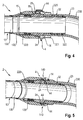
- the FIG. 4 shows a coupling device 2 in a sectional view with a nut member 120, which is welded here with a designed as a filler pipe 130 metallic pipe 13.
- the coupling device 2 shown is cut in a different plane than the previously shown coupling device 2 in the FIG. 3 .
- the father element 220 is connected to a conduit 23 made of a plastic material.
- a plastic material for example, a material such as HDPE or EVOH or any other suitable and corresponding fuel-resistant plastic is selected.
- the line 23 is z. B. formed as a filler neck 230.
- the male member 220 comprises a slip-on area 32 with a ribbed surface.
- the ribs 320 are arranged next to one another and in each case extend radially around the attachment region 32.
- a hose clamp 321 intended.
- a plastic material is selected for the line 23, which swells by the contact with the fuel to a certain extent, so that the hose clamp 321 can sit down.
- the attachment area 32 here comprises a radially extending O-ring 322 for sealing.
- the attachment region 32 is here connected to the father element 220 in a materially bonded manner.
- the slip-on region 32 is coupled to the region of the father element 220 which is otherwise provided for a material connection to a metal line.
- This has the advantage that no constructive changes to the father element 220 are necessary when plastic pipes or metallic pipes are used.
- the father element 220 and the Austeck Scheme 32 are welded together. It is also possible that a one-piece design of father element 220 and Austeck Scheme 32 is provided.
- FIG. 5 shows the coupling device 2 from the FIG. 4 in a perspective view in another sectional plane.
- the arrangement of the securing recesses 140 within the wall of the nut member 120 can be seen particularly well here. Good to see is the course of the spring clip 44 within the securing portion 14 after entry through the securing recess 140.
- the spring clip 44 extends through the securing recess 140 and lies behind the projection 24 so that a decoupling is positively prevented.
- FIG. 6 a coupling device 2 with a nut member 120 and a father element 220 is shown in a perspective view.
- nut element 120 and father element 220 are coupled and secured with spring clip 44.
- the spring clip 44 runs while in the nut member 120 and enters through the securing recesses 140 in the securing portion 14 and lies there behind the projection 24 of the father element 220.
- a slip-on area 32 or a metal pipe can be welded.
- the nut element 120 was not shown for the sake of clarity.
- the securing element 34 designed as a spring clip 44 is shown separately in perspective.
- the spring clip 44 is bent annularly.
- the intended for entry into the securing recess 140 areas of the spring clip 44 are slightly bent inwards.
- the spring clip 44 is formed at the ends with a corresponding bend as an assembly aid. At the outwardly bent ends, the spring clip 44 can be received, for example, in an assembly pliers or even used with his hands.
- the FIG. 7 shows that in the FIG. 6 shown father element 220 with an attached Aufsteck Scheme 32.
- the Aufsteck Scheme here comprises a plurality of ribs 320 and an O-ring 322nd
- a coupling device 2 is shown, which is equipped with an optical detection device for controlling a correctly made coupling of the coupling elements 12, 22.
- the nut member 120 has a viewing window 27.
- the viewing window 27 is formed here as a recess in the wall.
- the father element 220 comprises a marking element 17.
- the marking element 17 is visible within the viewing window 27. This means that the correct coupling can be monitored very quickly by means of a corresponding control view without lengthy tests extending the assembly time.
- the marking element 17 can be seen within the viewing window 27 when the spring clip 44 is positively engaged behind the projection 24 of the father element 220.
- the marking element 17 is here as a circumferential groove formed within the overlapping portion 5.
- a colored plastic ring can be inserted.
- an O-ring or the like is placed in the circumferential groove.
- a slotted plastic ring is particularly preferably, the color of the marking element 17 is different from the color of the O-rings used for sealing 16, 26, 322.
- the groove is coated in color, z. B. by painting.
Landscapes
- Engineering & Computer Science (AREA)
- Mechanical Engineering (AREA)
- General Engineering & Computer Science (AREA)
- Chemical & Material Sciences (AREA)
- Combustion & Propulsion (AREA)
- Life Sciences & Earth Sciences (AREA)
- Sustainable Development (AREA)
- Sustainable Energy (AREA)
- Transportation (AREA)
- Cooling, Air Intake And Gas Exhaust, And Fuel Tank Arrangements In Propulsion Units (AREA)
- Quick-Acting Or Multi-Walled Pipe Joints (AREA)
Applications Claiming Priority (1)
| Application Number | Priority Date | Filing Date | Title |
|---|---|---|---|
| DE102015111895.5A DE102015111895A1 (de) | 2015-07-22 | 2015-07-22 | Fahrzeugkomponente und Kraftfahrzeug |
Publications (2)
| Publication Number | Publication Date |
|---|---|
| EP3121501A1 true EP3121501A1 (fr) | 2017-01-25 |
| EP3121501B1 EP3121501B1 (fr) | 2020-07-08 |
Family
ID=56497626
Family Applications (1)
| Application Number | Title | Priority Date | Filing Date |
|---|---|---|---|
| EP16180261.6A Active EP3121501B1 (fr) | 2015-07-22 | 2016-07-20 | Vehicule automobile avec composant de vehicule |
Country Status (4)
| Country | Link |
|---|---|
| US (1) | US10486528B2 (fr) |
| EP (1) | EP3121501B1 (fr) |
| CN (1) | CN106369232B (fr) |
| DE (1) | DE102015111895A1 (fr) |
Cited By (2)
| Publication number | Priority date | Publication date | Assignee | Title |
|---|---|---|---|---|
| EP3522291A1 (fr) * | 2018-01-31 | 2019-08-07 | Samsung SDI Co., Ltd. | Ensemble de tube pour un système de distribution de fluide d'un bloc-batterie d'un véhicule et bloc-batterie destiné à un véhicule |
| CN111699337A (zh) * | 2018-01-31 | 2020-09-22 | 三星Sdi株式会社 | 用于车辆电池包的流体分配系统的管组件和用于车辆的电池包 |
Families Citing this family (8)
| Publication number | Priority date | Publication date | Assignee | Title |
|---|---|---|---|---|
| US11014442B2 (en) * | 2017-03-01 | 2021-05-25 | Stant Usa Corp. | Fuel tank fill pipe assembly |
| CA3056075C (fr) * | 2017-03-10 | 2022-06-07 | Aqseptence Group, Inc. | Tuyau polyvalent |
| US10781958B2 (en) * | 2017-10-31 | 2020-09-22 | Oetiker Ny, Inc. | Low peak insertion tube end form |
| US20190219207A1 (en) | 2018-01-16 | 2019-07-18 | Rain Bird Corporation | Push To Connect Coupling |
| EP3862609A4 (fr) * | 2018-10-05 | 2022-05-11 | J Juan, S.A. | Système d'accouplement fluidique |
| EP3854618B1 (fr) * | 2020-01-21 | 2022-03-09 | Magna Energy Storage Systems GesmbH | Réservoir de carburant comprenant un raccord |
| US12372181B2 (en) * | 2021-01-29 | 2025-07-29 | Hutchinson Fluid Management Systems, Inc. | High tolerance quick connect coupling |
| US12085216B2 (en) | 2022-02-17 | 2024-09-10 | Arctic Cat Inc. | Multi-use fuel filler tube |
Citations (6)
| Publication number | Priority date | Publication date | Assignee | Title |
|---|---|---|---|---|
| FR2331743A1 (fr) * | 1975-11-12 | 1977-06-10 | Ekman Kjell | Mecanisme de verrouillage pour dispositif de raccordement de tuyaux |
| DE10100128A1 (de) | 2000-01-24 | 2001-08-09 | Tesma Motoren Getriebetechnik | Anordnung zum Verbinden von zwei Rohren |
| DE102008005717A1 (de) | 2007-11-13 | 2009-02-26 | Alfmeier Präzision AG Baugruppen und Systemlösungen | Kraftstofftank mit einem Einfüllrohr und einem Einfüllstutzenkopf |
| EP2372209A2 (fr) * | 2010-03-30 | 2011-10-05 | NORMA Germany GmbH | Conduite de gaz d'échappement pour un véhicule automobile et installation de traitement des gaz d'échappement |
| DE202011105646U1 (de) | 2011-08-31 | 2012-12-03 | Reutter Gmbh | Anschlussverbindung zwischen einem rohrförmigen Tankstutzen und einem flexiblen Rohr |
| US20140209074A1 (en) * | 2013-01-25 | 2014-07-31 | A. Kayser Automotive Systems Gmbh | Crankcase ventilation for an internal combustion engine, tank ventilation conduit and connection system therefor |
Family Cites Families (60)
| Publication number | Priority date | Publication date | Assignee | Title |
|---|---|---|---|---|
| US738503A (en) * | 1902-12-11 | 1903-09-08 | Frederick R Waters | Pipe-coupling. |
| US794110A (en) * | 1904-09-20 | 1905-07-04 | Robert George Mcdowell | Coupling. |
| US3314696A (en) * | 1964-02-11 | 1967-04-18 | Perfecting Service Company | Quick connect coupling |
| US3584902A (en) * | 1969-07-09 | 1971-06-15 | Anchor Coupling Co Inc | Quick-connect safety coupling |
| US3625551A (en) * | 1970-02-25 | 1971-12-07 | Sta Rite Industries | Coupling for tubular members |
| US3753582A (en) * | 1971-11-09 | 1973-08-21 | Anarak Inc | Coupling unit |
| US3948548A (en) * | 1973-11-10 | 1976-04-06 | Armaturenfabrik Hermann Voss | Hose and pipe coupling |
| US3922011A (en) * | 1973-12-11 | 1975-11-25 | Tom Walters | Hose coupling |
| US4294473A (en) * | 1979-03-16 | 1981-10-13 | Ekman Engineering Ag | Device at mutually lockable first and second parts |
| SE459279B (sv) * | 1984-06-21 | 1989-06-19 | Volvo Ab | Kopplingsanordning vid tryckmediumledningar |
| US4884829A (en) * | 1986-09-16 | 1989-12-05 | Johannes Schaefer Vorm. Stettiner Schraubenwerke Gmbh & Co. Kg | Plug-in connection for connecting tube and host lines in particular for use in tube-line systems of motor vehicles |
| JPH0674875B2 (ja) * | 1988-12-07 | 1994-09-21 | エムス − インヴエンタ・アクチエンゲゼルシヤフト | 迅速断ち継ぎ継手 |
| DE4310192C2 (de) | 1992-07-28 | 2001-05-31 | Matsushita Electric Works Ltd | Schnellanschlußkupplung |
| DE4318878A1 (de) * | 1993-06-08 | 1994-12-15 | Kuehner Gmbh & Cie | Kältemittelkupplung zur Verbindung von Kältemittelleitungen |
| US5419594A (en) * | 1993-12-03 | 1995-05-30 | W. A. Thomas Co. | Quick-connect conduit coupling |
| DE9401501U1 (de) * | 1994-01-29 | 1994-03-10 | Armaturenfabrik Hermann Voss GmbH + Co, 51688 Wipperfürth | Steckkupplung für Druckleitungssysteme |
| DE19522691A1 (de) * | 1995-06-22 | 1997-01-02 | Henn Gmbh & Co Kg | Steckverbindung für den Anschluß von Rohr- und Schlauchleitungen |
| GB9703004D0 (en) * | 1997-02-13 | 1997-04-02 | Guest John Eng | Improvements in or relating to connectors for coupling tubes |
| EP0905430B1 (fr) * | 1997-09-30 | 2010-04-14 | Nitta Moore Company | Raccord de tuyaux |
| JP3561440B2 (ja) * | 1999-07-01 | 2004-09-02 | Smc株式会社 | 管継手 |
| DE19957946B4 (de) * | 1999-12-02 | 2005-07-14 | Behr Gmbh & Co. Kg | Anschlußstutzen für einen Wärmeübertrager |
| FR2802276B1 (fr) * | 1999-12-13 | 2002-06-07 | Nobel Plastiques | Dispositif de raccordement a basse permeabilite |
| FR2820489B1 (fr) * | 2001-02-05 | 2004-01-23 | Valeo | Dispositif de branchement d'alimentation pour un systeme a pression de fluide |
| US6554322B2 (en) * | 2001-05-21 | 2003-04-29 | Thach Duong | Controller valve coupling |
| JP3990558B2 (ja) * | 2001-10-31 | 2007-10-17 | 本田技研工業株式会社 | 配管ジョイント構造 |
| DE10206852B4 (de) * | 2002-02-18 | 2009-02-12 | Walterscheid Rohrverbindungstechnik Gmbh | Kupplung zum Verbinden von Hydraulikleitungen |
| US6595556B1 (en) * | 2002-03-14 | 2003-07-22 | Minature Precision Components, Inc. | Cartridge-type quick connector |
| FR2843624A1 (fr) * | 2002-08-13 | 2004-02-20 | Valeo Embrayages | Dispositif de branchement d'alimentation pour un systeme a pression de fluide |
| JP4291989B2 (ja) * | 2002-10-01 | 2009-07-08 | 株式会社パイオラックス | 配管用コネクタ |
| US6880862B2 (en) * | 2003-04-10 | 2005-04-19 | Dayco Products, Llc | Conductive tubular insert for a fuel transport system, and method |
| JP2005180662A (ja) * | 2003-12-22 | 2005-07-07 | Honda Motor Co Ltd | 樹脂チューブ付クイックコネクタ |
| US7497478B2 (en) * | 2004-07-29 | 2009-03-03 | Miniature Precision Components, Inc. | Duct assembly |
| US7806213B2 (en) * | 2004-12-17 | 2010-10-05 | Tokai Rubber Industries, Ltd. | Piping structure for transporting a fuel |
| JP2006226421A (ja) * | 2005-02-18 | 2006-08-31 | Tokai Rubber Ind Ltd | コネクタ取り付け構造 |
| JP4644063B2 (ja) * | 2005-07-26 | 2011-03-02 | 豊田合成株式会社 | 管接続構造体 |
| NO20060792L (no) * | 2005-08-31 | 2007-03-01 | Chris Reidar Frolich Braathen | Tilkoplingsventil |
| JP2007132449A (ja) * | 2005-11-11 | 2007-05-31 | Bosch Corp | 循環用コネクタ及び循環用コネクタの接続構造並びに燃料循環システム |
| BRPI0505733A (pt) * | 2005-12-19 | 2007-09-25 | Click Automotiva Ind Ltda | conector compacto |
| JP4864692B2 (ja) * | 2006-12-27 | 2012-02-01 | 株式会社デンソー | 配管継手装置及びその製造方法 |
| US7699356B2 (en) * | 2007-05-10 | 2010-04-20 | Craig Assgembly, Inc. | Quick connector for fluid conduit |
| JP4767912B2 (ja) * | 2007-06-12 | 2011-09-07 | 本田技研工業株式会社 | コネクタの脱落防止構造およびコネクタの脱落防止方法 |
| DE202007013347U1 (de) * | 2007-09-24 | 2007-11-22 | Dichtungstechnik Wallstabe & Schneider Gmbh & Co. Kg | Dichteinrichtung insbesondere für Steckkupplungen |
| US20090230674A1 (en) * | 2008-03-14 | 2009-09-17 | Gm Global Technology Operations, Inc. | Fuel Port Elbow Having a Truncated Conductive Insert Tube |
| JP5402340B2 (ja) * | 2008-08-28 | 2014-01-29 | 豊田合成株式会社 | 配管の接続構造体 |
| JP5435980B2 (ja) * | 2009-02-25 | 2014-03-05 | 本田技研工業株式会社 | クイックコネクタの解除器具 |
| US8740256B2 (en) * | 2010-05-04 | 2014-06-03 | Norma U.S. Holding Llc | Quick connector assembly |
| GB201014511D0 (en) * | 2010-09-01 | 2010-10-13 | Herrera Derek | Drill pipe connection |
| DE102010048107A1 (de) * | 2010-10-09 | 2012-04-12 | Norma Germany Gmbh | Verbindungselement für eine Fluidverbindung |
| JP5354393B2 (ja) * | 2011-03-28 | 2013-11-27 | 株式会社デンソー | 筒部材取付装置 |
| JP5844231B2 (ja) * | 2011-09-29 | 2016-01-13 | 豊田合成株式会社 | コネクタ |
| EP2597348A1 (fr) * | 2011-11-24 | 2013-05-29 | Eaton Germany GmbH | Connexion raccordable dotée d'une pince de rétention |
| DE202011052283U1 (de) * | 2011-12-13 | 2013-03-14 | Caterpillar Global Mining Europe Gmbh | Steckverbindung mit Sicherungselement und Sicherungselement hierfür |
| DE102012000607A1 (de) * | 2012-01-16 | 2013-07-18 | Norma Germany Gmbh | Kupplungselement und Entriegelungselement für das Kupplungselement |
| DE102012005930A1 (de) * | 2012-03-26 | 2013-09-26 | Veritas Ag | Steckverbindungsanordnung |
| EP3332938B1 (fr) * | 2012-07-02 | 2020-04-22 | Norma U.S. Holding LLC | Raccord de conduite de carburant, procédé de fabrication |
| US9409475B2 (en) * | 2013-02-08 | 2016-08-09 | Norma U.S. Holding Llc | Fuel line connector assembly |
| FR3007813B1 (fr) * | 2013-06-28 | 2016-01-01 | Sartorius Stedim Biotech | Connecteur fluidique avec collier et protection. |
| KR101500408B1 (ko) * | 2013-12-12 | 2015-03-09 | 현대자동차 주식회사 | 커플링 |
| US9939095B2 (en) * | 2014-01-29 | 2018-04-10 | The Boeing Company | Tube fitting |
| US10337656B2 (en) * | 2015-10-27 | 2019-07-02 | Ford Global Technologies, Llc | Quick connect with visual indicator |
-
2015
- 2015-07-22 DE DE102015111895.5A patent/DE102015111895A1/de not_active Withdrawn
-
2016
- 2016-07-15 US US15/210,906 patent/US10486528B2/en active Active
- 2016-07-20 EP EP16180261.6A patent/EP3121501B1/fr active Active
- 2016-07-21 CN CN201610580103.9A patent/CN106369232B/zh active Active
Patent Citations (6)
| Publication number | Priority date | Publication date | Assignee | Title |
|---|---|---|---|---|
| FR2331743A1 (fr) * | 1975-11-12 | 1977-06-10 | Ekman Kjell | Mecanisme de verrouillage pour dispositif de raccordement de tuyaux |
| DE10100128A1 (de) | 2000-01-24 | 2001-08-09 | Tesma Motoren Getriebetechnik | Anordnung zum Verbinden von zwei Rohren |
| DE102008005717A1 (de) | 2007-11-13 | 2009-02-26 | Alfmeier Präzision AG Baugruppen und Systemlösungen | Kraftstofftank mit einem Einfüllrohr und einem Einfüllstutzenkopf |
| EP2372209A2 (fr) * | 2010-03-30 | 2011-10-05 | NORMA Germany GmbH | Conduite de gaz d'échappement pour un véhicule automobile et installation de traitement des gaz d'échappement |
| DE202011105646U1 (de) | 2011-08-31 | 2012-12-03 | Reutter Gmbh | Anschlussverbindung zwischen einem rohrförmigen Tankstutzen und einem flexiblen Rohr |
| US20140209074A1 (en) * | 2013-01-25 | 2014-07-31 | A. Kayser Automotive Systems Gmbh | Crankcase ventilation for an internal combustion engine, tank ventilation conduit and connection system therefor |
Cited By (2)
| Publication number | Priority date | Publication date | Assignee | Title |
|---|---|---|---|---|
| EP3522291A1 (fr) * | 2018-01-31 | 2019-08-07 | Samsung SDI Co., Ltd. | Ensemble de tube pour un système de distribution de fluide d'un bloc-batterie d'un véhicule et bloc-batterie destiné à un véhicule |
| CN111699337A (zh) * | 2018-01-31 | 2020-09-22 | 三星Sdi株式会社 | 用于车辆电池包的流体分配系统的管组件和用于车辆的电池包 |
Also Published As
| Publication number | Publication date |
|---|---|
| US10486528B2 (en) | 2019-11-26 |
| CN106369232B (zh) | 2021-05-25 |
| DE102015111895A1 (de) | 2017-01-26 |
| US20170021723A1 (en) | 2017-01-26 |
| EP3121501B1 (fr) | 2020-07-08 |
| CN106369232A (zh) | 2017-02-01 |
Similar Documents
| Publication | Publication Date | Title |
|---|---|---|
| EP3121501B1 (fr) | Vehicule automobile avec composant de vehicule | |
| DE102013101109B4 (de) | System und Setzwerkzeug zum Befestigen eines Einpressstutzens an einem Rohr | |
| EP1939514A1 (fr) | Dispositif de liaison doté de raccords tubulaires destinés à relier des éléments de réception de fluide | |
| EP1635103B1 (fr) | Raccord détachable à fiche pour des tuyaux ou similaires | |
| EP2492569A2 (fr) | Liaison pour manchon | |
| DE102006030428A1 (de) | Schnellsteckverbindung | |
| WO2013030102A1 (fr) | Appareil de montage préalable de bague coupante pour raccords filetés pour tube | |
| EP2669561A1 (fr) | Dispositif de liaison de conduits | |
| EP1798459A1 (fr) | Dispositif de raccord de tuyaux en deux demi-colliers de retenue | |
| DE10347927B4 (de) | Verfahren und Vorrichtung zur Herstellung einer Rohrpressverbindung an einer Steckverbindung | |
| EP2019246A2 (fr) | Dispositif de fixation d'un circuit ayant un diamètre extérieur profilé et procédé de montage | |
| DE102016001874A1 (de) | Profilschelle zur Verbindung zweier Rohrleitungen | |
| EP3397889B1 (fr) | Dispositif de raccordement | |
| EP3107794A1 (fr) | Direction de véhicule automobile, outil auxiliaire de montage et procédé de montage d'une direction de véhicule automobile | |
| DE102008051303A1 (de) | Verschlusskupplung | |
| DE102008005619A1 (de) | Schnellverschluss | |
| DE202011103941U1 (de) | Rohrverbinder | |
| EP2053298A1 (fr) | Agencement de distributeur | |
| EP3584487B1 (fr) | Système de gaz d'échappement avec bride tubulaire | |
| DE102010012523A1 (de) | Vorrichtung zum Verbinden mit einer Rohr- oder Schlauchleitung, insbesondere Klemmringverschraubung | |
| DE102011012376A1 (de) | Rohr-Schlauch-Anordnung | |
| DE102004016051A1 (de) | Bremskraftverstärker | |
| DE102008058675A1 (de) | Steckverbindung | |
| DE102004001109B4 (de) | Fluidleitung für Fahrzeuge | |
| DE29818534U1 (de) | Verbindung für Rohr- und/oder Schlauchleitungen |
Legal Events
| Date | Code | Title | Description |
|---|---|---|---|
| PUAI | Public reference made under article 153(3) epc to a published international application that has entered the european phase |
Free format text: ORIGINAL CODE: 0009012 |
|
| STAA | Information on the status of an ep patent application or granted ep patent |
Free format text: STATUS: THE APPLICATION HAS BEEN PUBLISHED |
|
| AK | Designated contracting states |
Kind code of ref document: A1 Designated state(s): AL AT BE BG CH CY CZ DE DK EE ES FI FR GB GR HR HU IE IS IT LI LT LU LV MC MK MT NL NO PL PT RO RS SE SI SK SM TR |
|
| AX | Request for extension of the european patent |
Extension state: BA ME |
|
| STAA | Information on the status of an ep patent application or granted ep patent |
Free format text: STATUS: REQUEST FOR EXAMINATION WAS MADE |
|
| 17P | Request for examination filed |
Effective date: 20170718 |
|
| RBV | Designated contracting states (corrected) |
Designated state(s): AL AT BE BG CH CY CZ DE DK EE ES FI FR GB GR HR HU IE IS IT LI LT LU LV MC MK MT NL NO PL PT RO RS SE SI SK SM TR |
|
| STAA | Information on the status of an ep patent application or granted ep patent |
Free format text: STATUS: EXAMINATION IS IN PROGRESS |
|
| 17Q | First examination report despatched |
Effective date: 20190618 |
|
| GRAP | Despatch of communication of intention to grant a patent |
Free format text: ORIGINAL CODE: EPIDOSNIGR1 |
|
| STAA | Information on the status of an ep patent application or granted ep patent |
Free format text: STATUS: GRANT OF PATENT IS INTENDED |
|
| INTG | Intention to grant announced |
Effective date: 20200124 |
|
| GRAS | Grant fee paid |
Free format text: ORIGINAL CODE: EPIDOSNIGR3 |
|
| GRAA | (expected) grant |
Free format text: ORIGINAL CODE: 0009210 |
|
| STAA | Information on the status of an ep patent application or granted ep patent |
Free format text: STATUS: THE PATENT HAS BEEN GRANTED |
|
| AK | Designated contracting states |
Kind code of ref document: B1 Designated state(s): AL AT BE BG CH CY CZ DE DK EE ES FI FR GB GR HR HU IE IS IT LI LT LU LV MC MK MT NL NO PL PT RO RS SE SI SK SM TR |
|
| REG | Reference to a national code |
Ref country code: CH Ref legal event code: EP Ref country code: AT Ref legal event code: REF Ref document number: 1288834 Country of ref document: AT Kind code of ref document: T Effective date: 20200715 |
|
| REG | Reference to a national code |
Ref country code: DE Ref legal event code: R096 Ref document number: 502016010424 Country of ref document: DE |
|
| REG | Reference to a national code |
Ref country code: IE Ref legal event code: FG4D Free format text: LANGUAGE OF EP DOCUMENT: GERMAN |
|
| RAP2 | Party data changed (patent owner data changed or rights of a patent transferred) |
Owner name: MAGNA STEYR FUEL SYSTEMS GESMBH |
|
| REG | Reference to a national code |
Ref country code: GB Ref legal event code: 732E Free format text: REGISTERED BETWEEN 20201008 AND 20201014 |
|
| REG | Reference to a national code |
Ref country code: DE Ref legal event code: R082 Ref document number: 502016010424 Country of ref document: DE Representative=s name: QUERMANN STURM WEILNAU PATENTANWAELTE PARTNERS, DE Ref country code: DE Ref legal event code: R081 Ref document number: 502016010424 Country of ref document: DE Owner name: MAGNA STEYR FUEL SYSTEMS GESMBH, AT Free format text: FORMER OWNERS: DR. ING. H.C. F. PORSCHE AG, 70435 STUTTGART, DE; MAGNA STEYR FUEL SYSTEMS GESMBH, 8261 SINABELKIRCHEN, AT Ref country code: DE Ref legal event code: R082 Ref document number: 502016010424 Country of ref document: DE Representative=s name: PATENTANWAELTE STURM WEILNAU FRANKE PARTNERSCH, DE |
|
| REG | Reference to a national code |
Ref country code: LT Ref legal event code: MG4D |
|
| REG | Reference to a national code |
Ref country code: NL Ref legal event code: MP Effective date: 20200708 |
|
| PG25 | Lapsed in a contracting state [announced via postgrant information from national office to epo] |
Ref country code: FI Free format text: LAPSE BECAUSE OF FAILURE TO SUBMIT A TRANSLATION OF THE DESCRIPTION OR TO PAY THE FEE WITHIN THE PRESCRIBED TIME-LIMIT Effective date: 20200708 Ref country code: LT Free format text: LAPSE BECAUSE OF FAILURE TO SUBMIT A TRANSLATION OF THE DESCRIPTION OR TO PAY THE FEE WITHIN THE PRESCRIBED TIME-LIMIT Effective date: 20200708 Ref country code: PT Free format text: LAPSE BECAUSE OF FAILURE TO SUBMIT A TRANSLATION OF THE DESCRIPTION OR TO PAY THE FEE WITHIN THE PRESCRIBED TIME-LIMIT Effective date: 20201109 Ref country code: BG Free format text: LAPSE BECAUSE OF FAILURE TO SUBMIT A TRANSLATION OF THE DESCRIPTION OR TO PAY THE FEE WITHIN THE PRESCRIBED TIME-LIMIT Effective date: 20201008 Ref country code: ES Free format text: LAPSE BECAUSE OF FAILURE TO SUBMIT A TRANSLATION OF THE DESCRIPTION OR TO PAY THE FEE WITHIN THE PRESCRIBED TIME-LIMIT Effective date: 20200708 Ref country code: NO Free format text: LAPSE BECAUSE OF FAILURE TO SUBMIT A TRANSLATION OF THE DESCRIPTION OR TO PAY THE FEE WITHIN THE PRESCRIBED TIME-LIMIT Effective date: 20201008 Ref country code: GR Free format text: LAPSE BECAUSE OF FAILURE TO SUBMIT A TRANSLATION OF THE DESCRIPTION OR TO PAY THE FEE WITHIN THE PRESCRIBED TIME-LIMIT Effective date: 20201009 Ref country code: HR Free format text: LAPSE BECAUSE OF FAILURE TO SUBMIT A TRANSLATION OF THE DESCRIPTION OR TO PAY THE FEE WITHIN THE PRESCRIBED TIME-LIMIT Effective date: 20200708 Ref country code: SE Free format text: LAPSE BECAUSE OF FAILURE TO SUBMIT A TRANSLATION OF THE DESCRIPTION OR TO PAY THE FEE WITHIN THE PRESCRIBED TIME-LIMIT Effective date: 20200708 |
|
| PG25 | Lapsed in a contracting state [announced via postgrant information from national office to epo] |
Ref country code: PL Free format text: LAPSE BECAUSE OF FAILURE TO SUBMIT A TRANSLATION OF THE DESCRIPTION OR TO PAY THE FEE WITHIN THE PRESCRIBED TIME-LIMIT Effective date: 20200708 Ref country code: LV Free format text: LAPSE BECAUSE OF FAILURE TO SUBMIT A TRANSLATION OF THE DESCRIPTION OR TO PAY THE FEE WITHIN THE PRESCRIBED TIME-LIMIT Effective date: 20200708 Ref country code: RS Free format text: LAPSE BECAUSE OF FAILURE TO SUBMIT A TRANSLATION OF THE DESCRIPTION OR TO PAY THE FEE WITHIN THE PRESCRIBED TIME-LIMIT Effective date: 20200708 Ref country code: IS Free format text: LAPSE BECAUSE OF FAILURE TO SUBMIT A TRANSLATION OF THE DESCRIPTION OR TO PAY THE FEE WITHIN THE PRESCRIBED TIME-LIMIT Effective date: 20201108 |
|
| REG | Reference to a national code |
Ref country code: CH Ref legal event code: PL |
|
| PG25 | Lapsed in a contracting state [announced via postgrant information from national office to epo] |
Ref country code: NL Free format text: LAPSE BECAUSE OF FAILURE TO SUBMIT A TRANSLATION OF THE DESCRIPTION OR TO PAY THE FEE WITHIN THE PRESCRIBED TIME-LIMIT Effective date: 20200708 |
|
| REG | Reference to a national code |
Ref country code: DE Ref legal event code: R097 Ref document number: 502016010424 Country of ref document: DE |
|
| REG | Reference to a national code |
Ref country code: BE Ref legal event code: MM Effective date: 20200731 |
|
| PG25 | Lapsed in a contracting state [announced via postgrant information from national office to epo] |
Ref country code: LU Free format text: LAPSE BECAUSE OF NON-PAYMENT OF DUE FEES Effective date: 20200720 Ref country code: LI Free format text: LAPSE BECAUSE OF NON-PAYMENT OF DUE FEES Effective date: 20200731 Ref country code: MC Free format text: LAPSE BECAUSE OF FAILURE TO SUBMIT A TRANSLATION OF THE DESCRIPTION OR TO PAY THE FEE WITHIN THE PRESCRIBED TIME-LIMIT Effective date: 20200708 Ref country code: CH Free format text: LAPSE BECAUSE OF NON-PAYMENT OF DUE FEES Effective date: 20200731 Ref country code: CZ Free format text: LAPSE BECAUSE OF FAILURE TO SUBMIT A TRANSLATION OF THE DESCRIPTION OR TO PAY THE FEE WITHIN THE PRESCRIBED TIME-LIMIT Effective date: 20200708 Ref country code: DK Free format text: LAPSE BECAUSE OF FAILURE TO SUBMIT A TRANSLATION OF THE DESCRIPTION OR TO PAY THE FEE WITHIN THE PRESCRIBED TIME-LIMIT Effective date: 20200708 Ref country code: RO Free format text: LAPSE BECAUSE OF FAILURE TO SUBMIT A TRANSLATION OF THE DESCRIPTION OR TO PAY THE FEE WITHIN THE PRESCRIBED TIME-LIMIT Effective date: 20200708 Ref country code: SM Free format text: LAPSE BECAUSE OF FAILURE TO SUBMIT A TRANSLATION OF THE DESCRIPTION OR TO PAY THE FEE WITHIN THE PRESCRIBED TIME-LIMIT Effective date: 20200708 Ref country code: IT Free format text: LAPSE BECAUSE OF FAILURE TO SUBMIT A TRANSLATION OF THE DESCRIPTION OR TO PAY THE FEE WITHIN THE PRESCRIBED TIME-LIMIT Effective date: 20200708 Ref country code: EE Free format text: LAPSE BECAUSE OF FAILURE TO SUBMIT A TRANSLATION OF THE DESCRIPTION OR TO PAY THE FEE WITHIN THE PRESCRIBED TIME-LIMIT Effective date: 20200708 |
|
| PLBE | No opposition filed within time limit |
Free format text: ORIGINAL CODE: 0009261 |
|
| STAA | Information on the status of an ep patent application or granted ep patent |
Free format text: STATUS: NO OPPOSITION FILED WITHIN TIME LIMIT |
|
| PG25 | Lapsed in a contracting state [announced via postgrant information from national office to epo] |
Ref country code: BE Free format text: LAPSE BECAUSE OF NON-PAYMENT OF DUE FEES Effective date: 20200731 Ref country code: AL Free format text: LAPSE BECAUSE OF FAILURE TO SUBMIT A TRANSLATION OF THE DESCRIPTION OR TO PAY THE FEE WITHIN THE PRESCRIBED TIME-LIMIT Effective date: 20200708 |
|
| 26N | No opposition filed |
Effective date: 20210409 |
|
| PG25 | Lapsed in a contracting state [announced via postgrant information from national office to epo] |
Ref country code: SK Free format text: LAPSE BECAUSE OF FAILURE TO SUBMIT A TRANSLATION OF THE DESCRIPTION OR TO PAY THE FEE WITHIN THE PRESCRIBED TIME-LIMIT Effective date: 20200708 |
|
| PG25 | Lapsed in a contracting state [announced via postgrant information from national office to epo] |
Ref country code: SI Free format text: LAPSE BECAUSE OF FAILURE TO SUBMIT A TRANSLATION OF THE DESCRIPTION OR TO PAY THE FEE WITHIN THE PRESCRIBED TIME-LIMIT Effective date: 20200708 Ref country code: IE Free format text: LAPSE BECAUSE OF NON-PAYMENT OF DUE FEES Effective date: 20200720 |
|
| PG25 | Lapsed in a contracting state [announced via postgrant information from national office to epo] |
Ref country code: TR Free format text: LAPSE BECAUSE OF FAILURE TO SUBMIT A TRANSLATION OF THE DESCRIPTION OR TO PAY THE FEE WITHIN THE PRESCRIBED TIME-LIMIT Effective date: 20200708 Ref country code: MT Free format text: LAPSE BECAUSE OF FAILURE TO SUBMIT A TRANSLATION OF THE DESCRIPTION OR TO PAY THE FEE WITHIN THE PRESCRIBED TIME-LIMIT Effective date: 20200708 Ref country code: CY Free format text: LAPSE BECAUSE OF FAILURE TO SUBMIT A TRANSLATION OF THE DESCRIPTION OR TO PAY THE FEE WITHIN THE PRESCRIBED TIME-LIMIT Effective date: 20200708 |
|
| PG25 | Lapsed in a contracting state [announced via postgrant information from national office to epo] |
Ref country code: MK Free format text: LAPSE BECAUSE OF FAILURE TO SUBMIT A TRANSLATION OF THE DESCRIPTION OR TO PAY THE FEE WITHIN THE PRESCRIBED TIME-LIMIT Effective date: 20200708 |
|
| REG | Reference to a national code |
Ref country code: AT Ref legal event code: MM01 Ref document number: 1288834 Country of ref document: AT Kind code of ref document: T Effective date: 20210720 |
|
| PG25 | Lapsed in a contracting state [announced via postgrant information from national office to epo] |
Ref country code: AT Free format text: LAPSE BECAUSE OF NON-PAYMENT OF DUE FEES Effective date: 20210720 |
|
| PGFP | Annual fee paid to national office [announced via postgrant information from national office to epo] |
Ref country code: DE Payment date: 20250722 Year of fee payment: 10 |
|
| PGFP | Annual fee paid to national office [announced via postgrant information from national office to epo] |
Ref country code: GB Payment date: 20250722 Year of fee payment: 10 |
|
| PGFP | Annual fee paid to national office [announced via postgrant information from national office to epo] |
Ref country code: FR Payment date: 20250725 Year of fee payment: 10 |