EP3121505A1 - Vorrichtung zur aufnahme eines kryofluids - Google Patents
Vorrichtung zur aufnahme eines kryofluids Download PDFInfo
- Publication number
- EP3121505A1 EP3121505A1 EP15178170.5A EP15178170A EP3121505A1 EP 3121505 A1 EP3121505 A1 EP 3121505A1 EP 15178170 A EP15178170 A EP 15178170A EP 3121505 A1 EP3121505 A1 EP 3121505A1
- Authority
- EP
- European Patent Office
- Prior art keywords
- heat exchanger
- jacket
- cryocontainer
- gusset
- cover
- Prior art date
- Legal status (The legal status is an assumption and is not a legal conclusion. Google has not performed a legal analysis and makes no representation as to the accuracy of the status listed.)
- Granted
Links
Images

Classifications
-
- F—MECHANICAL ENGINEERING; LIGHTING; HEATING; WEAPONS; BLASTING
- F17—STORING OR DISTRIBUTING GASES OR LIQUIDS
- F17C—VESSELS FOR CONTAINING OR STORING COMPRESSED, LIQUEFIED OR SOLIDIFIED GASES; FIXED-CAPACITY GAS-HOLDERS; FILLING VESSELS WITH, OR DISCHARGING FROM VESSELS, COMPRESSED, LIQUEFIED, OR SOLIDIFIED GASES
- F17C7/00—Methods or apparatus for discharging liquefied, solidified, or compressed gases from pressure vessels, not covered by another subclass
- F17C7/02—Discharging liquefied gases
- F17C7/04—Discharging liquefied gases with change of state, e.g. vaporisation
-
- F—MECHANICAL ENGINEERING; LIGHTING; HEATING; WEAPONS; BLASTING
- F17—STORING OR DISTRIBUTING GASES OR LIQUIDS
- F17C—VESSELS FOR CONTAINING OR STORING COMPRESSED, LIQUEFIED OR SOLIDIFIED GASES; FIXED-CAPACITY GAS-HOLDERS; FILLING VESSELS WITH, OR DISCHARGING FROM VESSELS, COMPRESSED, LIQUEFIED, OR SOLIDIFIED GASES
- F17C2201/00—Vessel construction, in particular geometry, arrangement or size
- F17C2201/01—Shape
- F17C2201/0104—Shape cylindrical
- F17C2201/0109—Shape cylindrical with exteriorly curved end-piece
-
- F—MECHANICAL ENGINEERING; LIGHTING; HEATING; WEAPONS; BLASTING
- F17—STORING OR DISTRIBUTING GASES OR LIQUIDS
- F17C—VESSELS FOR CONTAINING OR STORING COMPRESSED, LIQUEFIED OR SOLIDIFIED GASES; FIXED-CAPACITY GAS-HOLDERS; FILLING VESSELS WITH, OR DISCHARGING FROM VESSELS, COMPRESSED, LIQUEFIED, OR SOLIDIFIED GASES
- F17C2201/00—Vessel construction, in particular geometry, arrangement or size
- F17C2201/03—Orientation
- F17C2201/035—Orientation with substantially horizontal main axis
-
- F—MECHANICAL ENGINEERING; LIGHTING; HEATING; WEAPONS; BLASTING
- F17—STORING OR DISTRIBUTING GASES OR LIQUIDS
- F17C—VESSELS FOR CONTAINING OR STORING COMPRESSED, LIQUEFIED OR SOLIDIFIED GASES; FIXED-CAPACITY GAS-HOLDERS; FILLING VESSELS WITH, OR DISCHARGING FROM VESSELS, COMPRESSED, LIQUEFIED, OR SOLIDIFIED GASES
- F17C2201/00—Vessel construction, in particular geometry, arrangement or size
- F17C2201/05—Size
- F17C2201/054—Size medium (>1 m3)
-
- F—MECHANICAL ENGINEERING; LIGHTING; HEATING; WEAPONS; BLASTING
- F17—STORING OR DISTRIBUTING GASES OR LIQUIDS
- F17C—VESSELS FOR CONTAINING OR STORING COMPRESSED, LIQUEFIED OR SOLIDIFIED GASES; FIXED-CAPACITY GAS-HOLDERS; FILLING VESSELS WITH, OR DISCHARGING FROM VESSELS, COMPRESSED, LIQUEFIED, OR SOLIDIFIED GASES
- F17C2201/00—Vessel construction, in particular geometry, arrangement or size
- F17C2201/05—Size
- F17C2201/056—Small (<1 m3)
-
- F—MECHANICAL ENGINEERING; LIGHTING; HEATING; WEAPONS; BLASTING
- F17—STORING OR DISTRIBUTING GASES OR LIQUIDS
- F17C—VESSELS FOR CONTAINING OR STORING COMPRESSED, LIQUEFIED OR SOLIDIFIED GASES; FIXED-CAPACITY GAS-HOLDERS; FILLING VESSELS WITH, OR DISCHARGING FROM VESSELS, COMPRESSED, LIQUEFIED, OR SOLIDIFIED GASES
- F17C2205/00—Vessel construction, in particular mounting arrangements, attachments or identifications means
- F17C2205/01—Mounting arrangements
- F17C2205/0103—Exterior arrangements
- F17C2205/0115—Dismountable protective hulls
-
- F—MECHANICAL ENGINEERING; LIGHTING; HEATING; WEAPONS; BLASTING
- F17—STORING OR DISTRIBUTING GASES OR LIQUIDS
- F17C—VESSELS FOR CONTAINING OR STORING COMPRESSED, LIQUEFIED OR SOLIDIFIED GASES; FIXED-CAPACITY GAS-HOLDERS; FILLING VESSELS WITH, OR DISCHARGING FROM VESSELS, COMPRESSED, LIQUEFIED, OR SOLIDIFIED GASES
- F17C2205/00—Vessel construction, in particular mounting arrangements, attachments or identifications means
- F17C2205/03—Fluid connections, filters, valves, closure means or other attachments
- F17C2205/0302—Fittings, valves, filters, or components in connection with the gas storage device
- F17C2205/0323—Valves
- F17C2205/0329—Valves manually actuated
-
- F—MECHANICAL ENGINEERING; LIGHTING; HEATING; WEAPONS; BLASTING
- F17—STORING OR DISTRIBUTING GASES OR LIQUIDS
- F17C—VESSELS FOR CONTAINING OR STORING COMPRESSED, LIQUEFIED OR SOLIDIFIED GASES; FIXED-CAPACITY GAS-HOLDERS; FILLING VESSELS WITH, OR DISCHARGING FROM VESSELS, COMPRESSED, LIQUEFIED, OR SOLIDIFIED GASES
- F17C2221/00—Handled fluid, in particular type of fluid
- F17C2221/01—Pure fluids
- F17C2221/012—Hydrogen
-
- F—MECHANICAL ENGINEERING; LIGHTING; HEATING; WEAPONS; BLASTING
- F17—STORING OR DISTRIBUTING GASES OR LIQUIDS
- F17C—VESSELS FOR CONTAINING OR STORING COMPRESSED, LIQUEFIED OR SOLIDIFIED GASES; FIXED-CAPACITY GAS-HOLDERS; FILLING VESSELS WITH, OR DISCHARGING FROM VESSELS, COMPRESSED, LIQUEFIED, OR SOLIDIFIED GASES
- F17C2221/00—Handled fluid, in particular type of fluid
- F17C2221/01—Pure fluids
- F17C2221/014—Nitrogen
-
- F—MECHANICAL ENGINEERING; LIGHTING; HEATING; WEAPONS; BLASTING
- F17—STORING OR DISTRIBUTING GASES OR LIQUIDS
- F17C—VESSELS FOR CONTAINING OR STORING COMPRESSED, LIQUEFIED OR SOLIDIFIED GASES; FIXED-CAPACITY GAS-HOLDERS; FILLING VESSELS WITH, OR DISCHARGING FROM VESSELS, COMPRESSED, LIQUEFIED, OR SOLIDIFIED GASES
- F17C2221/00—Handled fluid, in particular type of fluid
- F17C2221/03—Mixtures
- F17C2221/032—Hydrocarbons
- F17C2221/033—Methane, e.g. natural gas, CNG, LNG, GNL, GNC, PLNG
-
- F—MECHANICAL ENGINEERING; LIGHTING; HEATING; WEAPONS; BLASTING
- F17—STORING OR DISTRIBUTING GASES OR LIQUIDS
- F17C—VESSELS FOR CONTAINING OR STORING COMPRESSED, LIQUEFIED OR SOLIDIFIED GASES; FIXED-CAPACITY GAS-HOLDERS; FILLING VESSELS WITH, OR DISCHARGING FROM VESSELS, COMPRESSED, LIQUEFIED, OR SOLIDIFIED GASES
- F17C2223/00—Handled fluid before transfer, i.e. state of fluid when stored in the vessel or before transfer from the vessel
- F17C2223/01—Handled fluid before transfer, i.e. state of fluid when stored in the vessel or before transfer from the vessel characterised by the phase
- F17C2223/0146—Two-phase
- F17C2223/0153—Liquefied gas, e.g. LPG, GPL
- F17C2223/0161—Liquefied gas, e.g. LPG, GPL cryogenic, e.g. LNG, GNL, PLNG
-
- F—MECHANICAL ENGINEERING; LIGHTING; HEATING; WEAPONS; BLASTING
- F17—STORING OR DISTRIBUTING GASES OR LIQUIDS
- F17C—VESSELS FOR CONTAINING OR STORING COMPRESSED, LIQUEFIED OR SOLIDIFIED GASES; FIXED-CAPACITY GAS-HOLDERS; FILLING VESSELS WITH, OR DISCHARGING FROM VESSELS, COMPRESSED, LIQUEFIED, OR SOLIDIFIED GASES
- F17C2223/00—Handled fluid before transfer, i.e. state of fluid when stored in the vessel or before transfer from the vessel
- F17C2223/03—Handled fluid before transfer, i.e. state of fluid when stored in the vessel or before transfer from the vessel characterised by the pressure level
- F17C2223/033—Small pressure, e.g. for liquefied gas
-
- F—MECHANICAL ENGINEERING; LIGHTING; HEATING; WEAPONS; BLASTING
- F17—STORING OR DISTRIBUTING GASES OR LIQUIDS
- F17C—VESSELS FOR CONTAINING OR STORING COMPRESSED, LIQUEFIED OR SOLIDIFIED GASES; FIXED-CAPACITY GAS-HOLDERS; FILLING VESSELS WITH, OR DISCHARGING FROM VESSELS, COMPRESSED, LIQUEFIED, OR SOLIDIFIED GASES
- F17C2225/00—Handled fluid after transfer, i.e. state of fluid after transfer from the vessel
- F17C2225/01—Handled fluid after transfer, i.e. state of fluid after transfer from the vessel characterised by the phase
- F17C2225/0107—Single phase
- F17C2225/0123—Single phase gaseous, e.g. CNG, GNC
-
- F—MECHANICAL ENGINEERING; LIGHTING; HEATING; WEAPONS; BLASTING
- F17—STORING OR DISTRIBUTING GASES OR LIQUIDS
- F17C—VESSELS FOR CONTAINING OR STORING COMPRESSED, LIQUEFIED OR SOLIDIFIED GASES; FIXED-CAPACITY GAS-HOLDERS; FILLING VESSELS WITH, OR DISCHARGING FROM VESSELS, COMPRESSED, LIQUEFIED, OR SOLIDIFIED GASES
- F17C2227/00—Transfer of fluids, i.e. method or means for transferring the fluid; Heat exchange with the fluid
- F17C2227/03—Heat exchange with the fluid
- F17C2227/0302—Heat exchange with the fluid by heating
- F17C2227/0309—Heat exchange with the fluid by heating using another fluid
- F17C2227/0316—Water heating
-
- F—MECHANICAL ENGINEERING; LIGHTING; HEATING; WEAPONS; BLASTING
- F17—STORING OR DISTRIBUTING GASES OR LIQUIDS
- F17C—VESSELS FOR CONTAINING OR STORING COMPRESSED, LIQUEFIED OR SOLIDIFIED GASES; FIXED-CAPACITY GAS-HOLDERS; FILLING VESSELS WITH, OR DISCHARGING FROM VESSELS, COMPRESSED, LIQUEFIED, OR SOLIDIFIED GASES
- F17C2227/00—Transfer of fluids, i.e. method or means for transferring the fluid; Heat exchange with the fluid
- F17C2227/03—Heat exchange with the fluid
- F17C2227/0302—Heat exchange with the fluid by heating
- F17C2227/0309—Heat exchange with the fluid by heating using another fluid
- F17C2227/0323—Heat exchange with the fluid by heating using another fluid in a closed loop
-
- F—MECHANICAL ENGINEERING; LIGHTING; HEATING; WEAPONS; BLASTING
- F17—STORING OR DISTRIBUTING GASES OR LIQUIDS
- F17C—VESSELS FOR CONTAINING OR STORING COMPRESSED, LIQUEFIED OR SOLIDIFIED GASES; FIXED-CAPACITY GAS-HOLDERS; FILLING VESSELS WITH, OR DISCHARGING FROM VESSELS, COMPRESSED, LIQUEFIED, OR SOLIDIFIED GASES
- F17C2227/00—Transfer of fluids, i.e. method or means for transferring the fluid; Heat exchange with the fluid
- F17C2227/03—Heat exchange with the fluid
- F17C2227/0367—Localisation of heat exchange
- F17C2227/0369—Localisation of heat exchange in or on a vessel
- F17C2227/0376—Localisation of heat exchange in or on a vessel in wall contact
- F17C2227/0383—Localisation of heat exchange in or on a vessel in wall contact outside the vessel
-
- F—MECHANICAL ENGINEERING; LIGHTING; HEATING; WEAPONS; BLASTING
- F17—STORING OR DISTRIBUTING GASES OR LIQUIDS
- F17C—VESSELS FOR CONTAINING OR STORING COMPRESSED, LIQUEFIED OR SOLIDIFIED GASES; FIXED-CAPACITY GAS-HOLDERS; FILLING VESSELS WITH, OR DISCHARGING FROM VESSELS, COMPRESSED, LIQUEFIED, OR SOLIDIFIED GASES
- F17C2250/00—Accessories; Control means; Indicating, measuring or monitoring of parameters
- F17C2250/04—Indicating or measuring of parameters as input values
- F17C2250/0404—Parameters indicated or measured
- F17C2250/043—Pressure
-
- F—MECHANICAL ENGINEERING; LIGHTING; HEATING; WEAPONS; BLASTING
- F17—STORING OR DISTRIBUTING GASES OR LIQUIDS
- F17C—VESSELS FOR CONTAINING OR STORING COMPRESSED, LIQUEFIED OR SOLIDIFIED GASES; FIXED-CAPACITY GAS-HOLDERS; FILLING VESSELS WITH, OR DISCHARGING FROM VESSELS, COMPRESSED, LIQUEFIED, OR SOLIDIFIED GASES
- F17C2260/00—Purposes of gas storage and gas handling
- F17C2260/01—Improving mechanical properties or manufacturing
- F17C2260/018—Adapting dimensions
-
- F—MECHANICAL ENGINEERING; LIGHTING; HEATING; WEAPONS; BLASTING
- F17—STORING OR DISTRIBUTING GASES OR LIQUIDS
- F17C—VESSELS FOR CONTAINING OR STORING COMPRESSED, LIQUEFIED OR SOLIDIFIED GASES; FIXED-CAPACITY GAS-HOLDERS; FILLING VESSELS WITH, OR DISCHARGING FROM VESSELS, COMPRESSED, LIQUEFIED, OR SOLIDIFIED GASES
- F17C2265/00—Effects achieved by gas storage or gas handling
- F17C2265/06—Fluid distribution
- F17C2265/066—Fluid distribution for feeding engines for propulsion
-
- F—MECHANICAL ENGINEERING; LIGHTING; HEATING; WEAPONS; BLASTING
- F17—STORING OR DISTRIBUTING GASES OR LIQUIDS
- F17C—VESSELS FOR CONTAINING OR STORING COMPRESSED, LIQUEFIED OR SOLIDIFIED GASES; FIXED-CAPACITY GAS-HOLDERS; FILLING VESSELS WITH, OR DISCHARGING FROM VESSELS, COMPRESSED, LIQUEFIED, OR SOLIDIFIED GASES
- F17C2270/00—Applications
- F17C2270/01—Applications for fluid transport or storage
- F17C2270/0165—Applications for fluid transport or storage on the road
- F17C2270/0168—Applications for fluid transport or storage on the road by vehicles
-
- F—MECHANICAL ENGINEERING; LIGHTING; HEATING; WEAPONS; BLASTING
- F17—STORING OR DISTRIBUTING GASES OR LIQUIDS
- F17C—VESSELS FOR CONTAINING OR STORING COMPRESSED, LIQUEFIED OR SOLIDIFIED GASES; FIXED-CAPACITY GAS-HOLDERS; FILLING VESSELS WITH, OR DISCHARGING FROM VESSELS, COMPRESSED, LIQUEFIED, OR SOLIDIFIED GASES
- F17C2270/00—Applications
- F17C2270/01—Applications for fluid transport or storage
- F17C2270/0165—Applications for fluid transport or storage on the road
- F17C2270/0168—Applications for fluid transport or storage on the road by vehicles
- F17C2270/0171—Trucks
-
- Y—GENERAL TAGGING OF NEW TECHNOLOGICAL DEVELOPMENTS; GENERAL TAGGING OF CROSS-SECTIONAL TECHNOLOGIES SPANNING OVER SEVERAL SECTIONS OF THE IPC; TECHNICAL SUBJECTS COVERED BY FORMER USPC CROSS-REFERENCE ART COLLECTIONS [XRACs] AND DIGESTS
- Y02—TECHNOLOGIES OR APPLICATIONS FOR MITIGATION OR ADAPTATION AGAINST CLIMATE CHANGE
- Y02E—REDUCTION OF GREENHOUSE GAS [GHG] EMISSIONS, RELATED TO ENERGY GENERATION, TRANSMISSION OR DISTRIBUTION
- Y02E60/00—Enabling technologies; Technologies with a potential or indirect contribution to GHG emissions mitigation
- Y02E60/30—Hydrogen technology
- Y02E60/32—Hydrogen storage
Definitions
- the present invention relates to a device for receiving a cryofluid, in particular LNG fuel, comprising a vehicle-mounted cryocontainer having a generally cylindrical shell and a heat exchanger connected to the cryocontainer for evaporating the cryogenic fluid.
- cryogenic temperature In order to increase the energy content of energy carriers, which are gaseous under normal conditions, they are cooled for transport and storage purposes to cryogenic temperature and thereby at least partially liquefied into a cryogenic fluid and stored in temperature-insulated cryocontainers.
- driving vehicles e.g. Liquefied natural gas (liquefied natural gas, LNG) or liquefied hydrogen stored as Kryofluide with high energy density to be subsequently used for the operation of essentially conventional internal combustion engines or fuel cells of the vehicles.
- cryofluid stored in the liquid state is converted back into a gaseous state by means of a heat exchanger.
- heat exchangers of this type require a lot of space on the vehicle.
- a curved heat exchanger installed on one of the end caps.
- such a heat exchanger takes up a lot of space in front of the end cap, whereby the length of the cryocontainer is severely limited and only little space for the valves located in this area is available.
- the invention has for its object to provide a device which better utilizes the existing space.
- the heat exchanger is no longer - as in the known constructions - installed on a front side of the cryocontainer or another location in the vehicle, but on the longitudinal side of the cryocontainer in one of said "jacket gusset".
- the cryocontainer can be made longer, thus significantly increasing the volume of entrained fuel.
- the invention thus allows a much better utilization of the available space.
- the heat exchanger on the long side of the cryocontainer is easily accessible, which makes it easy to maintain.
- said gusset faces away from the side of the cryocontainer designed to be mounted on a support bracket of the vehicle.
- the heat exchanger does not hinder the installation of the cryocontainer on the support bracket or on the vehicle.
- the heat exchanger is particularly easily accessible when it is located on the side facing away from the vehicle.
- gusset is used for the heat exchanger, which is in the mounting position of the device on the top of the cryocontainer, whereby the heat exchanger is better protected in the vehicle operation from falling rocks.
- the heat exchanger is substantially rod-shaped and is parallel to the cylinder axis of the shell on the outside thereof.
- the outer shape of the heat exchanger can also be adapted as much as possible to the shape of the gusset, which is formed from the difference amount cuboid - coat. Under rod is understood a straight shape with any cross-section.
- the length of the heat exchanger may correspond to the length of the shell, or only a portion thereof, to accommodate further fittings in the same gusset.
- the cross section of the heat exchanger is substantially round in order to use particularly inexpensive and robust heat exchangers can.
- the cross section of the heat exchanger is adapted on its side facing the jacket to the curvature of the shell, whereby the heat exchanger can be particularly well attached to the jacket. Furthermore, so the available space can be exploited even better.
- the heat exchanger may for example be a double tube heat exchanger, which is guided in a U-shape or meandering over the outside of the shell and rests against this. This is also particularly advantageous if the device by means of straps, which run around the cryocontainer, is lashed to the support brackets. The heat exchanger is subject to less stress in such flat designs.
- cryocontainer comprises a convex end cap with an apex plane
- a line emerging from an exit or inlet of the heat exchanger may be formed by a gusset between the end cap and said apex plane ("cap wrap"). ) are passed.
- the heat exchanger protrudes beyond the length of the jacket at at least one end, where at least one line extending essentially radially from the heat exchanger can be guided there in the direction of the vehicle.
- This allows particularly straight and therefore short and robust lines, which can also be passed directly through said cap wrapper there.
- the length of the heat exchanger can be made as large as possible in order to achieve a high efficiency of the heat exchanger.
- a line extending substantially radially from the heat exchanger can also be routed via the jacket in the direction of the vehicle.
- the heat exchanger can be made particularly short to install next to this other fittings.
- the device has a cover covering said heat exchanger, which preferably has a rounded L-shaped contour, viewed in the direction of the cylinder axis of the jacket.
- the heat exchanger can be shielded from external influences such as precipitation, contamination or falling rocks.
- the device can be mounted well by means of straps on support brackets of the vehicle by means of such a construction.
- the cover is located within said gusset to take advantage of the largest possible space without increasing the width of the cryocontainer.
- the device preferably also has a cap cover for an end cap of the cryocontainer, which is aligned with the cover in the direction of the cylinder axis of the shell.
- the cover engages over the heat exchanger with normal to the cylinder axis of the shell side walls, whereby the heat exchanger of the shell and the cover can be completely enclosed.
- the cover also houses fittings connected to the cryocontainer or to the heat exchanger, which in turn are located in said gusset.
- fittings can be, for example, between the cryocontainer and the heat exchanger, for example, a shut-off valve or a pressure gauge, or be connected downstream of the heat exchanger.
- the valves can be connected to the cryocontainer independently of the heat exchanger and, for example, as a refueling coupling, Vent connection or associated hand valve be executed.
- At least one of the mentioned fittings is preferably accessible through an opening in the cover in order to be able to operate the fittings simply.
- the openings may themselves be e.g. covered with lids.
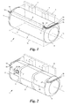
- Fig. 1 shows a device 1 with a cryocontainer 2, comprising a cylindrical shell 3 and two end caps 4, 5, for receiving a Kryofluids.
- the cryofluid may be, for example, natural gas, which can be used at temperatures of up to -161 ° C and a Pressure of up to 16 bar is at least partially liquefied (liquefied natural gas, LNG).
- LNG liquefied natural gas
- Kryofluid eg liquefied hydrogen
- the device 1 is mounted, for example in the manner of a conventional fuel tank laterally on the chassis or frame 6 or behind the cab of a commercial vehicle, not shown, for example, a truck or passenger car (PKWs), and can do this with standardized console systems, eg L. - or sickle-shaped support brackets 7 ( Fig. 3 ), cooperate, on which it is fixed by means of straps 7 'to the support brackets 7.
- console systems eg L. - or sickle-shaped support brackets 7 ( Fig. 3 )
- cryogenic fluid may also be a refrigerant, for example liquid nitrogen, with which the cooling system is operated by cooling fans, e.g. of food transporters.
- the device 1 can also be used for storing such refrigerants on trucks or truck trailers.
- the device 1 In order to convert the cryofluid stored in the cryocontainer 2 in the liquid state into a gaseous state, the device 1 has a heat exchanger 8.
- the heat exchanger 8 is located in a space or gusset 9a ("jacket gusset", see also FIG Fig. 3 ), which is enclosed between the shell 3 and a smallest possible, the jacket 3 circumscribing, imaginary cuboid 10.
- gusset 9a (“jacket gusset", see also FIG Fig. 3 )
- the jacket 3 circumscribing, imaginary cuboid 10.
- the heat exchanger 8 is rod-shaped and arranged parallel to the cylinder axis 11 of the shell 3 on the outside thereof.
- Under rod is understood to mean an elongated, straight shape with any cross-section.
- the cross section of the heat exchanger 8 may be substantially round (see Fig. 1 ) or on its side facing the shell 3 to the curvature of the shell 3 (see Fig. 7a and 7b ).
- the heat exchanger 8 may be a double-tube heat exchanger, i. a tube-in-tube or coaxial heat exchanger, which is guided in a U-shaped or meandering manner over the outside of the jacket 3 and bears against it.
- the heat exchanger 8 may be formed, for example, as a cross-flow or cross-countercurrent heat exchanger, plate heat exchanger, spiral heat exchanger, shell and tube heat exchanger, U-tube heat exchanger, jacket tube heat exchanger, heater coil or countercurrent layer heat exchanger.
- an outlet line 12 of the cryocontainer 2 is connected to an inlet 13 of the heat exchanger 8.
- the cryofluid After the cryofluid has passed through the heat exchanger 8, it can be supplied via a connected to an output 14 of the heat exchanger 8 line 15, for example, the engine of the vehicle.
- the heat exchanger 8 also has an input 16 and an output 17 and connected thereto Lines 18, 19 for heat exchange medium, eg engine coolant.
- the outputs 14, 16 and the input 17 terminate in a plane normal to the cylinder axis 11 of the shell, whereby the lines 15, 18, 19 extend in the region of the heat exchanger 8 parallel to the cylinder axis 11 in the gusset 9a.
- the cryocontainer 2 may be optionally provided with a removable cover 20 to protect the heat exchanger 8.
- the cover 20 has seen in the direction of the cylinder axis 11 approximately rounded L-shaped contour, wherein the cover 20 is in this embodiment, within said gusset 9a, to take maximum advantage of the available space.
- the cover 20 may also have to the cylinder axis 11 of the shell 3 normal side walls 21, 22 which engage over the heat exchanger 8 at least partially.
- the cover 20 with its side walls 21, 22 in conjunction with the jacket 3 surrounds the heat exchanger 8 on all sides.
- a manual valve 23 in the line 12 for interrupting the connection between the heat exchanger 8 and cryocontainer 2 and a pressure gauge 24 in the line 12 for pressure indication of prevailing in the cryocontainer 2 gas pressure are accessible via openings 25, 26 in the cover 20.
- a refueling coupling (not shown) for filling the cryocontainer 2 and an outlet including manual valve (not shown) for manual reduction of prevailing in the cryocontainer 2 gas pressure from the cover 20 are covered, which can be designed for this purpose, for example, hinged or partially openable ,
- the refueling coupling, the outlet and the manual valve are each connected to lines of the cryocontainer 2 and usually not connected to the heat exchanger 8.
- Fig. 3 shows the said gusset 9a, which is located in the mounting position of the device 1 on the top of the cryocontainer 2 and the side facing away from the cryocontainer 2, which is designed for mounting on the support bracket 7 of the vehicle. This is advantageous for easy accessibility of the fittings 23, 24, protection against stone chipping and unimpeded installation of the device 1 on the support bracket 7.
- the heat exchanger 8 or the cover 20 may also be located in one of the three other gussets 9b, 9c, 9d, whereby components other than the heat exchanger 8 may be located in the former gusset 9a, e.g. the refueling coupling or a treading device for entry into the driver's cab of the vehicle.
- the lengths of the lines 15, 18, 19 can be kept particularly short.
- Fig. 4 shows the embodiment of the end cap 4 as a convex end cap 4 with a top plane 27.
- Cap Envelope gusset 9 e
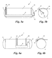
- the length of the heat exchanger 8 is not dependent on the length of the cryocontainer 2 and may be substantially as long as the shell 3, as in Fig. 1 shown, or even longer, as in the Fig. 5a and 5b shown. In the latter embodiment, the heat exchanger 8 protrudes beyond the length of the jacket 3 with both ends-alternatively only with one of its two ends.
- the lines 12, 15, 18, 19 are performed by the heat exchanger 8, starting in the direction of the vehicle and thereby go through the cap coats 9e.
- the line 12 is connected to a connecting piece 25 of the end cap 4.
- the Fig. 6a and 6b show an embodiment in which the heat exchanger 8 is shorter than the shell 3.
- the lines 12, 15, 18, 19 can be out of the gusset 9a out and over the jacket 3.
- the lines 12, 15, 18, 19 can also be guided through the gusset 9b in order to save installation space.
- the line 12 is in this case connected to a connecting piece 25 in the jacket 3.
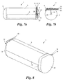
- Fig. 7a and 7b show an embodiment in which all lines 12, 15, 18, 19 are guided over a single one of the two cap coats 9e. If the heat exchanger 8 is a Double pipe or coaxial heat exchanger, two of the lines can be performed in a double tube 26, 27 respectively.
- Fig. 8 shows that at least one of the end caps 4, 5 can be provided with a cap cover 28.
- the cap lid 28 can be aligned with the cover 20 - as seen in the direction of the cylinder axis 11.
- the cover 20 can protrude beyond the jacket 3 in the direction of the cylinder axis 11 in order to terminate flush with the cap cover 28, or the cover 20 and cap wrapper 28 can partially overlap there.
- the jacket 3 is in the Fig. 1 - 8 however, in other embodiments may also be generally cylindrical.
- the term "generally cylindrical” is understood to mean a cylinder having an arbitrary base or cross-sectional area, be it circular, oval, rectangular, square or square with rounded corners or otherwise shaped.
- the sheath 3 may in particular also have a D-shaped cross-section, in which case only two sheath gussets are available on the round side of the "D".
Landscapes
- Engineering & Computer Science (AREA)
- Mechanical Engineering (AREA)
- General Engineering & Computer Science (AREA)
- Filling Or Discharging Of Gas Storage Vessels (AREA)
- Cooling, Air Intake And Gas Exhaust, And Fuel Tank Arrangements In Propulsion Units (AREA)
Abstract
Description
- Die vorliegende Erfindung betrifft eine Vorrichtung zur Aufnahme eines Kryofluids, insbesondere von LNG-Kraftstoff, umfassend einen an einem Fahrzeug montierbaren Kryobehälter mit einem allgemein-zylindrischen Mantel sowie einen an den Kryobehälter angeschlossenen Wärmetauscher zur Verdampfung des Kryofluids.
- Um den Energiegehalt von Energieträgern, welche unter Normalbedingungen gasförmig sind, zu erhöhen, werden diese für Transport- und Lagerungszwecke auf Tieftemperatur abgekühlt und dabei zu einem Kryofluid zumindest teilverflüssigt und in temperaturisolierten Kryobehältern gespeichert. Zum Antrieb von Fahrzeugen werden z.B. verflüssigtes Erdgas (liquefied natural gas, LNG) oder verflüssigter Wasserstoff als Kryofluide mit hoher Energiedichte gespeichert, um hinterher zum Betrieb von im wesentlichen herkömmlichen Verbrennungskraftmaschinen oder Brennstoffzellen der Fahrzeuge genutzt zu werden.
- Zu diesem Zweck wird das im flüssigen Zustand gespeicherte Kryofluid mittels eines Wärmetauschers in einen gasförmigen Zustand rückgewandelt. Wärmetauscher dieser Art benötigen jedoch viel Platz am Fahrzeug. So wird z.B. in der
EP 2 765 296 A1 ein gekrümmter Wärmetauscher an einer der Endkappen verbaut. Ein solcher Wärmetauscher nimmt jedoch viel Platz vor der Endkappe ein, wodurch die Länge des Kryobehälters stark eingeschränkt ist und nur wenig Platz für die sich in diesem Bereich befindlichen Armaturen zur Verfügung steht. - Die Erfindung setzt sich zum Ziel, eine Vorrichtung zu schaffen, welche den bestehenden Bauraum besser ausnutzt.
- Dieses Ziel wird mit einer Vorrichtung der einleitend genannten Art erreicht, die sich gemäß der Erfindung dadurch auszeichnet, dass sich der Wärmetauscher zumindest teilweise in einem Zwickel befindet, der zwischen dem Mantel und dem kleinstmöglichen, den Mantel umschreibenden, gedachten Quader eingeschlossen ist.
- Erfindungsgemäß wird der Wärmetauscher nicht mehr - wie bei den bekannten Konstruktionen - an einer Stirnseite des Kryobehälters oder einer anderen Stelle im Fahrzeug verbaut, sondern an der Längsseite des Kryobehälters in einem der genannten "Mantelzwickel". Durch den solcherart am Behälterende eingesparten Platz kann der Kryobehälter länger ausgeführt werden, womit das Volumen des mitgeführten Kraftstoffs signifikant erhöht werden kann. Die Erfindung ermöglicht damit eine wesentlich bessere Ausnutzung des zur Verfügung stehenden Bauraums. Weiters ist der Wärmetauscher an der Längsseite des Kryobehälters gut zugänglich, wodurch er leicht gewartet werden kann.
- In einer bevorzugten Ausführungsform der Erfindung ist der genannte Zwickel jener Seite des Kryobehälters abgewandt, die zur Montage an einer Tragkonsole des Fahrzeugs ausgebildet ist. Dadurch behindert der Wärmetauscher nicht die Montage des Kryobehälters an der Tragkonsole bzw. am Fahrzeug. Darüber hinaus ist der Wärmetauscher besonders leicht zugänglich, wenn er an der dem Fahrzeug abgewandten Seite liegt.
- Gemäß einem weiteren bevorzugten Merkmal der Erfindung wird für den Wärmetauscher insbesondere jener Zwickel verwendet, der in der Montagestellung der Vorrichtung auf der Oberseite des Kryobehälters liegt, wodurch der Wärmetauscher im Fahrzeugbetrieb besser vor Steinschlag geschützt ist.
- Bevorzugt ist der Wärmetauscher im Wesentlichen stabförmig und liegt parallel zur Zylinderachse des Mantels an dessen Außenseite. Die Außenform des Wärmetauschers kann dabei auch größtmöglich an die Form des Zwickels angepasst werden, die aus der Differenzmenge Quader - Mantel gebildet wird. Unter stabförmig wird eine gerade Form mit beliebigem Querschnitt verstanden. Die Länge des Wärmetauschers kann der Länge des Mantels entsprechen oder nur einen Teil davon, um weitere Armaturen im selben Zwickel unterzubringen.
- Bevorzugt ist der Querschnitt des Wärmetauschers im Wesentlichen rund, um besonders kostengünstige und robuste Wärmetauscher einsetzen zu können.
- Alternativ ist der Querschnitt des Wärmetauschers auf seiner dem Mantel zugewandten Seite an die Krümmung des Mantels angepasst, wodurch der Wärmetauscher besonders gut am Mantel angebracht werden kann. Weiters kann so der zur Verfügung stehende Bauraum noch besser ausgenutzt werden. Um einen besonders flachen, an die Krümmung der Mantelseite gut anpassbaren Wärmetauscher zu schaffen, kann der Wärmetauscher beispielsweise ein Doppelrohrwärmetauscher sein, der U-förmig oder mäanderförmig über die Außenseite des Mantels geführt ist und an dieser anliegt. Dies ist auch besonders dann von Vorteil, wenn die Vorrichtung mittels Spannbändern, die um den Kryobehälter verlaufen, an den Tragkonsolen festgezurrt wird. Der Wärmetauscher unterliegt bei solchen flachen Bauformen weniger Spannungen.
- Um die Leitungen besonders platzsparend in Richtung zum Fahrzeug zu führen, kann - wenn der Kryobehälter eine konvexe Endkappe mit einer Scheitelebene umfasst - eine von einem Ausgang oder einem Eingang des Wärmetauschers ausgehende Leitung durch einen Zwickel zwischen der Endkappe und der genannten Scheitelebene ("Kappenzwickel") hindurchgeführt werden.
- In einer bevorzugten Ausführungsform ragt der Wärmetauscher an zumindest einem Ende über die Länge des Mantels hinaus, wobei dort zumindest eine vom Wärmetauscher im Wesentlichen radial ausgehende Leitung in Richtung zum Fahrzeug geführt werden kann. Dies ermöglicht besonders gerade und damit kurze und robuste Leitungen, die dort auch direkt durch den genannten Kappenzwickel hindurch geführt werden können. Zudem kann die Länge des Wärmetauschers so groß wie möglich ausgeführt werden, um einen hohen Wirkungsgrad des Wärmetauschers zu erreichen.
- Alternativ oder zusätzlich kann eine vom Wärmetauscher im Wesentlichen radial ausgehende Leitung auch über den Mantel in Richtung zum Fahrzeugs geführt werden. Hierbei kann der Wärmetauscher besonders kurz ausgeführt werden, um neben diesem weitere Armaturen zu montieren.
- In jeder Ausführungsform ist es besonders günstig, wenn die Vorrichtung eine den genannten Wärmetauscher abdeckende Abdeckung hat, welche bevorzugt eine - in Richtung der Zylinderachse des Mantels gesehen - abgerundet L-förmige Kontur hat. Dadurch kann der Wärmetauscher von äußeren Einflüssen wie Niederschlag, Verschmutzung oder Steinschlag abgeschirmt werden. Zudem kann die Vorrichtung mittels einer solchen Bauweise besondern gut mittels Spannbändern an Tragkonsolen des Fahrzeugs montiert werden.
- Bevorzugt befindet sich die Abdeckung innerhalb des genannten Zwickels, um den größtmöglichem Bauraum auszunutzen, ohne die Breite des Kryobehälters zu vergrößern.
- Weiters weist die Vorrichtung bevorzugt auch einen Kappendeckel für eine Endkappe des Kryobehälters auf, der in Richtung der Zylinderachse des Mantels gesehen mit der Abdeckung fluchtet. Dadurch kann ein kombiniertes Abdecksystem sowohl für den Mantel- als auch für den Kappenzwickel geschaffen werden.
- In einer Ausführungsform übergreift die Abdeckung den Wärmetauscher mit zur Zylinderachse des Mantels normalen Seitenwänden, wodurch der Wärmetauscher von dem Mantel und der Abdeckung gänzlich umschlossen werden kann.
- In einer weiteren vorteilhaften Ausführungsform der Erfindung beherbergt die Abdeckung ferner an den Kryobehälter oder an den Wärmetauscher angeschlossene Armaturen, die sich wiederum im genannten Zwickel befinden. Diese Armaturen können beispielsweise zwischen dem Kryobehälter und dem Wärmetauscher liegen, z.B. ein Absperrventil oder eine Druckanzeige, oder auch dem Wärmetauscher nachgeschaltet sein. Alternativ oder zusätzlich können die Armaturen unabhängig vom Wärmetauscher an den Kryobehälter angeschlossen sein und z.B. als Betankungskupplung, Vent-Anschluss oder zugehöriges Handventil ausgeführt sein.
- Weiters bevorzugt ist in dieser Ausführungsform zumindest eine der genannten Armaturen durch eine Öffnung in der Abdeckung zugänglich, um die Armaturen einfach bedienen zu können. Die Öffnungen können ihrerseits z.B. mit Deckeln abgedeckt werden.
- Die Erfindung wird nachfolgend anhand von in den beigeschlossenen Zeichnungen dargestellten Ausführungsbeispielen näher erläutert. In den Zeichnungen zeigen:
-
Fig. 1 die erfindungsgemäße Vorrichtung gemäß einer ersten Ausführungsform in einer Perspektivansicht; -
Fig. 2 die erfindungsgemäße Vorrichtung gemäß einer zweiten Ausführungsform in einer Perspektivansicht; -
Fig. 3 die Vorrichtung vonFig. 2 in einer schematischen Stirnansicht; und -
Fig. 4 die Vorrichtung vonFig. 1 in einer schematischen Seitenansicht; - die
Fig. 5 - 7 weitere Ausführungsformen der erfindungsgemäßen Vorrichtung jeweils in einer Draufsicht (Fig. 5a, 6a ,7a ) und einer Stirnansicht (Fig. 5b, 6b ,7b ); und -
Fig. 8 eine weitere Ausführungsform der erfindungsgemäßen Vorrichtung in einer Perspektivansicht. -
Fig. 1 zeigt eine Vorrichtung 1 mit einem Kryobehälter 2, umfassend einen zylindrischen Mantel 3 und zwei Endkappen 4, 5, zur Aufnahme eines Kryofluids. Das Kryofluid kann beispielsweise Erdgas sein, das bei Temperaturen von bis zu -161°C und einem Druck von bis zu 16 bar zumindest teilweise verflüssigt vorliegt (liquefied natural gas, LNG). Alternativ kann ein vergleichbares, in Verbrennungskraftmaschinen oder Brennstoffzellen einsetzbares Kryofluid, z.B. verflüssigter Wasserstoff, im Kryobehälter 2 gespeichert sein. Die Vorrichtung 1 wird beispielsweise in der Art eines herkömmlichen Kraftstoffbehälters seitlich am Chassis bzw. Rahmen 6 oder hinter der Fahrerkabine eines nicht weiter dargestellten Nutzfahrzeugs, z.B. eines Lastkraftwagens (LKWs) oder Personenkraftwagens (PKWs), montiert und kann dazu mit standardisierten Konsolensystemen, z.B. L- oder sichelförmigen Tragkonsolen 7 (Fig. 3 ), zusammenwirken, auf denen sie mittels Spannbändern 7' an den Tragkonsolen 7 fixiert wird. - Das Kryofluid kann aber auch ein Kältemittel sein, beispielsweise Flüssigstickstoff, mit dem das Kühlsystem von Kühllastern betrieben wird, z.B. von Lebensmitteltransportern. Demgemäß kann die Vorrichtung 1 auch für die Speicherung solcher Kältemittel auf LKWs oder LKW-Anhängern verwendet werden.
- Um das im Kryobehälter 2 in flüssigem Zustand gespeicherte Kryofluid in einen gasförmigen Zustand umzuwandeln, verfügt die Vorrichtung 1 über einen Wärmetauscher 8. Der Wärmetauscher 8 befindet sich in einem Zwischenraum bzw. Zwickel 9a ("Mantelzwickel", siehe auch
Fig. 3 ), der zwischen dem Mantel 3 und einem kleinstmöglichen, den Mantel 3 umschreibenden, gedachten Quader 10 eingeschlossen ist. Durch die Ausnutzung des Mantelzwickels 9a für den Wärmetauscher 8 können eine größere Länge und somit ein größeres Volumen des Kryobehälters 2 im Vergleich zum Stand der Technik erreicht werden. - Für eine platzsparende Raumausnutzung ist der Wärmetauscher 8 stabförmig ausgebildet und parallel zur Zylinderachse 11 des Mantels 3 an dessen Außenseite angeordnet. Unter stabförmig wird dabei eine langgestreckte, gerade Form mit beliebigem Querschnitt verstanden.
- So kann der Querschnitt des Wärmetauschers 8 beispielsweise im Wesentlichen rund sein (siehe
Fig. 1 ) oder auf seiner dem Mantel 3 zugewandten Seite an die Krümmung des Mantels 3 angepasst sein (sieheFig. 7a und 7b ). - Beispielsweise kann der Wärmetauscher 8 ein Doppelrohrwärmetauscher sein, d.h. ein Rohr-in-Rohr- bzw. Koaxialwärmetauscher, der U-förmig oder mäanderförmig über die Außenseite des Mantels 3 geführt ist und an dieser anliegt. Alternativ kann der Wärmetauscher 8 beispielsweise als Kreuzstrom- oder Kreuzgegenstromwärmetauscher, Plattenwärmetauscher, Spiralwärmetauscher, Rohrbündelwärmetauscher, U-Rohrwärmetauscher, Mantelrohrwärmetauscher, Heizregister oder Gegenstrom-Schichtwärmetauscher ausgebildet sein.
- Um Kryofluid aus dem Kryobehälter 2 zu entnehmen, ist eine Ausgangsleitung 12 des Kryobehälters 2 mit einem Eingang 13 des Wärmetauschers 8 verbunden. Nachdem das Kryofluid den Wärmetauscher 8 durchlaufen hat, kann es über eine mit einem Ausgang 14 des Wärmetauschers 8 verbundene Leitung 15 z.B. dem Motor des Fahrzeugs zugeführt werden. Der Wärmetauscher 8 verfügt zudem über einen Eingang 16 und einen Ausgang 17 und daran angeschlossene Leitungen 18, 19 für Wärmetauschmedium, z.B. Motorkühlmittel. Die Ausgänge 14, 16 und der Eingang 17 münden in einer zur Zylinderachse 11 des Mantels normalen Ebene aus, wodurch die Leitungen 15, 18, 19 im Bereich des Wärmetauschers 8 parallel zur Zylinderachse 11 im Zwickel 9a verlaufen.
- Wie in
Fig. 2 gezeigt, kann der Kryobehälter 2 zum Schutz des Wärmetauschers 8 optional mit einer abnehmbaren Abdeckung 20 versehen werden. Die Abdeckung 20 hat in Richtung der Zylinderachse 11 gesehen etwa abgerundet L-förmige Kontur, wobei sich die Abdeckung 20 in dieser Ausführungsform innerhalb des genannten Zwickels 9a befindet, um den zur Verfügung stehenden Bauraum maximal auszunutzen. Die Abdeckung 20 kann ferner zur Zylinderachse 11 des Mantels 3 normale Seitenwände 21, 22 haben, welche den Wärmetauscher 8 zumindest teilweise übergreifen. Optional umhüllt die Abdeckung 20 mit ihren Seitenwänden 21, 22 in Verbindung mit dem Mantel 3 den Wärmetauscher 8 allseitig. - Ein Handventil 23 in der Leitung 12 zur Unterbrechung der Verbindung zwischen Wärmetauscher 8 und Kryobehälter 2 und ein Manometer 24 in der Leitung 12 zur Druckanzeige des im Kryobehälter 2 vorherrschenden Gasdrucks sind über Öffnungen 25, 26 in der Abdeckung 20 zugänglich. Weiters sind eine Betankungskupplung (nicht gezeigt) zur Füllung des Kryobehälters 2 sowie ein Auslass samt Handventil (nicht gezeigt) zur manuellen Reduzierung des im Kryobehälter 2 vorherrschenden Gasdrucks von der Abdeckung 20 abgedeckt, welche zu diesem Zweck z.B. auch aufklappbar oder teilweise öffenbar gestaltet sein kann. Die Betankungskupplung, der Auslass sowie das Handventil sind jeweils an Leitungen des Kryobehälters 2 angeschlossen und in der Regel nicht mit dem Wärmetauscher 8 verbunden.
-
Fig. 3 zeigt den genannten Zwickel 9a, der sich in der Montagestellung der Vorrichtung 1 auf der Oberseite des Kryobehälters 2 befindet und jener Seite des Kryobehälters 2 abgewandt ist, die zur Montage an der Tragkonsole 7 des Fahrzeugs ausgebildet ist. Dies ist vorteilhaft für eine leichte Zugänglichkeit der Armaturen 23, 24, Schutz vor Steinschlag und eine ungehinderte Montage der Vorrichtung 1 an der Tragkonsole 7. - Alternativ kann sich der Wärmetauscher 8 bzw. die Abdeckung 20 auch in einem der drei anderen Zwickel 9b, 9c, 9d befinden, wodurch sich andere Bauteile als der Wärmetauscher 8 im erstgenannten Zwickel 9a befinden können, z.B. die Betankungskupplung oder eine Trittvorrichtung zum Einstieg in die Fahrerkabine des Fahrzeugs.
- Bei einer Anbringung des Wärmetauschers 8 in den Zwickeln 9b, 9c, die jeweils jener Seite des Kryobehälters 2 zugewandt sind, die zur Montage an der Tragkonsole 7 des Fahrzeugs ausgebildet ist, können die Längen der Leitungen 15, 18, 19 besonders kurz gehalten werden.
-
Fig. 4 zeigt die Ausführung der Endkappe 4 als konvexe Endkappe 4 mit einer Scheitelebene 27. Die genannten, von einem Ausgang 14, 16 oder einem Eingang 13, 17 des Wärmetauschers 8 ausgehenden Leitungen 12, 15, 18, 19 sind in dieser Ausführungsform durch einen Zwickel 9e ("Kappenzwickel") hindurchgeführt, der zwischen der Endkappe 4 und der Scheitelebene 27 eingeschlossen ist. Dadurch wird erreicht, dass die vom Wärmetauscher 8 ausgehenden Leitungen 15, 18, 19 die Längserstreckung des Kryobehälters 2 nicht überragen, wenn sie das Fahrzeugchassis 6 erreichen; die gleiche Maßnahme kann auf Seite der Endkappe 5 für die Leitung 12 getroffen werden. - Die Länge des Wärmetauschers 8 ist nicht von der Länge des Kryobehälters 2 abhängig und kann im Wesentlichen so lange wie der Mantel 3 sein, wie in
Fig. 1 gezeigt, oder auch länger, wie in denFig. 5a und 5b gezeigt. In letzterer Ausführungsform ragt der Wärmetauscher 8 mit beiden - alternativ nur mit einem seiner beiden - Enden über die Länge des Mantels 3 hinaus. Hierbei können die Leitungen 12, 15, 18, 19 vom Wärmetauscher 8 ausgehend in Richtung zum Fahrzeug geführt werden und dabei den Kappenzwickel 9e durchlaufen. Die Leitung 12 ist dabei an einen Anschlussstutzen 25 der Endkappe 4 angeschlossen. - Die
Fig. 6a und 6b zeigen eine Ausführungsform, in der der Wärmetauscher 8 kürzer ist als der Mantel 3. Anstatt die Leitungen 12, 15, 18, 19 durch einen Kappenzwickel 9e zu führen, können sie aus dem Zwickel 9a heraus und über den Mantel 3 geführt werden. Optional können die Leitungen 12, 15, 18, 19 dabei auch durch den Zwickel 9b geführt werden, um Bauraum einzusparen. Die Leitung 12 ist hierbei an einen Anschlussstutzen 25 im Mantel 3 angeschlossen. - Die
Fig. 7a und 7b zeigen eine Ausführungsform, in der alle Leitungen 12, 15, 18, 19 über einen einzigen der beiden Kappenzwickel 9e geführt werden. Ist der Wärmetauscher 8 dabei ein Doppelrohr- bzw. Koaxialwärmetauscher, können jeweils zwei der Leitungen in einem Doppelrohr 26, 27 geführt werden. -
Fig. 8 zeigt, dass auch zumindest eine der Endkappen 4, 5 mit einem Kappendeckel 28 versehen werden kann. Der Kappendeckel 28 kann mit der Abdeckung 20 - gesehen in Richtung der Zylinderachse 11 - fluchten. Die Abdeckung 20 kann hierbei in Richtung der Zylinderachse 11 über den Mantel 3 hinausragen, um mit dem Kappendeckel 28 bündig abzuschließen, oder Abdeckung 20 und Kappenzwickel 28 können sich dort teilweise überlappen. - Der Mantel 3 ist in den
Fig. 1 - 8 zylindrisch dargestellt, kann in weiteren Ausführungsformen jedoch auch allgemein-zylindrisch sein. Unter dem Begriff "allgemeinzylindrisch" wird ein Zylinder mit einer beliebigen Grund- bzw. Querschnittsfläche verstanden, sei sie kreisrund, oval, rechteckig, quadratisch oder quadratisch mit abgerundeten Ecken oder sonstwie geformt. So kann der Mantel 3 in einer Ausführungsform insbesondere auch einen D-förmigen Querschnitt haben, wobei dann nur mehr zwei Mantelzwickel auf der runden Seite des "D" zur Verfügung stehen. - Die Erfindung ist demgemäß nicht auf die dargestellten Ausführungsformen beschränkt, sondern umfasst alle Varianten, Modifikationen und Kombinationen, die in den Rahmen der angeschlossenen Ansprüche fallen.
Claims (15)
- Vorrichtung zur Aufnahme eines Kryofluids, insbesondere von LNG-Kraftstoff, umfassend einen an einem Fahrzeug montierbaren Kryobehälter (2) mit einem allgemein-zylindrischen Mantel (3) sowie einen an den Kryobehälter (2) angeschlossenen Wärmetauscher (8) zur Verdampfung des Kryofluids, dadurch gekennzeichnet, dass sich der Wärmetauscher (8) zumindest teilweise in einem Zwickel (9a, 9b, 9c, 9d) befindet, der zwischen dem Mantel (3) und dem kleinstmöglichen, den Mantel (3) umschreibenden, gedachten Quader (10) eingeschlossen ist.
- Vorrichtung nach Anspruch 1, dadurch gekennzeichnet, dass der genannte Zwickel (9a, 9b, 9c, 9d) jener Seite des Kryobehälters (2) abgewandt ist, die zur Montage an einer Tragkonsole (7) des Fahrzeugs ausgebildet ist.
- Vorrichtung nach Anspruch 1 oder 2, dadurch gekennzeichnet, dass der genannte Zwickel (9a, 9b, 9c, 9d) in der Montagestellung der Vorrichtung (1) auf der Oberseite des Kryobehälters (2) liegt.
- Vorrichtung nach einem der Ansprüche 1 bis 3, dadurch gekennzeichnet, dass der Wärmetauscher (8) im Wesentlichen stabförmig ist und im Wesentlichen parallel zur Zylinderachse (11) des Mantels (3) an dessen Außenseite liegt.
- Vorrichtung nach einem der Ansprüche 1 bis 4, dadurch gekennzeichnet, dass der Querschnitt des Wärmetauschers (8) im Wesentlichen rund ist.
- Vorrichtung nach einem der Ansprüche 1 bis 4, dadurch gekennzeichnet, dass der Querschnitt des Wärmetauschers (8) auf seiner dem Mantel (3) zugewandten Seite an die Krümmung des Mantels (3) angepasst ist.
- Vorrichtung nach einem der Ansprüche 6, dadurch gekennzeichnet, dass der Wärmetauscher (8) ein Doppelrohrwärmetauscher ist, der U-förmig oder mäanderförmig über die Außenseite des Mantels (3) geführt ist und an dieser anliegt.
- Vorrichtung nach einem der Ansprüche 1 bis 7, dadurch gekennzeichnet, dass der Kryobehälter (2) eine konvexe Endkappe (4, 5) mit einer Scheitelebene (27) umfasst, und dass eine von einem Ausgang (14, 17) oder einem Eingang (16) des Wärmetauschers (8) ausgehende Leitung (12, 15, 18, 19) durch einen Zwickel (9e) zwischen der Endkappe (5) und der genannten Scheitelebene (27) hindurchgeführt ist.
- Vorrichtung nach einem der Ansprüche 1 bis 8, dadurch gekennzeichnet, dass der Wärmetauscher (8) an zumindest einem Ende über die Länge des Mantels (3) hinausragt und dort zumindest eine vom Wärmetauscher (8) im Wesentlichen radial ausgehende Leitung (12, 15, 18, 19) in Richtung zum Fahrzeug geführt ist.
- Vorrichtung nach einem der Ansprüche 1 bis 9, dadurch gekennzeichnet, dass zumindest eine vom Wärmetauscher (8) im Wesentlichen radial ausgehende Leitung (12, 15, 18, 19) über den Mantel (3) in Richtung zum Fahrzeugs geführt ist.
- Vorrichtung nach einem der Ansprüche 1 bis 10, gekennzeichnet durch eine den genannten Wärmetauscher (8) abdeckende Abdeckung (20), welche bevorzugt eine - in Richtung der Zylinderachse (11) des Mantels (3) gesehen - abgerundet L-förmige Kontur hat.
- Vorrichtung nach Anspruch 11, dadurch gekennzeichnet, dass sich die Abdeckung (20) innerhalb des genannten Zwickels (9a, 9b, 9c, 9d) befindet.
- Vorrichtung nach Anspruch 11 oder 12, dadurch gekennzeichnet, dass die Vorrichtung (1) ferner einen Kappendeckel (28) für eine Endkappe (4, 5) des Kryobehälters (2) aufweist, der in Richtung der Zylinderachse (11) des Mantels (3) gesehen mit der Abdeckung (20) fluchtet.
- Vorrichtung nach einem der Ansprüche 11 bis 13, dadurch gekennzeichnet, dass die Abdeckung (20) ferner an den Kryobehälter (2) oder an den Wärmetauscher (8) angeschlossene Armaturen (23, 24) beherbergt, die sich wiederum im genannten Zwickel (9a, 9b, 9c, 9d) befinden.
- Vorrichtung nach Anspruch 14, dadurch gekennzeichnet, dass zumindest eine der genannten Armaturen (23, 24) durch eine Öffnung in der Abdeckung (20) zugänglich ist.
Priority Applications (2)
| Application Number | Priority Date | Filing Date | Title |
|---|---|---|---|
| ES15178170.5T ES2673600T3 (es) | 2015-07-24 | 2015-07-24 | Dispositivo para albergar un fluido criogénico |
| EP15178170.5A EP3121505B1 (de) | 2015-07-24 | 2015-07-24 | Vorrichtung zur aufnahme eines kryofluids |
Applications Claiming Priority (1)
| Application Number | Priority Date | Filing Date | Title |
|---|---|---|---|
| EP15178170.5A EP3121505B1 (de) | 2015-07-24 | 2015-07-24 | Vorrichtung zur aufnahme eines kryofluids |
Publications (2)
| Publication Number | Publication Date |
|---|---|
| EP3121505A1 true EP3121505A1 (de) | 2017-01-25 |
| EP3121505B1 EP3121505B1 (de) | 2018-03-14 |
Family
ID=53724050
Family Applications (1)
| Application Number | Title | Priority Date | Filing Date |
|---|---|---|---|
| EP15178170.5A Active EP3121505B1 (de) | 2015-07-24 | 2015-07-24 | Vorrichtung zur aufnahme eines kryofluids |
Country Status (2)
| Country | Link |
|---|---|
| EP (1) | EP3121505B1 (de) |
| ES (1) | ES2673600T3 (de) |
Cited By (8)
| Publication number | Priority date | Publication date | Assignee | Title |
|---|---|---|---|---|
| WO2021042143A1 (de) | 2019-09-05 | 2021-03-11 | Cryoshelter Gmbh | Befestigungssystem für einen kryobehälter mit einem aus dem behältermantel ragenden anschluss |
| EP3964744A1 (de) * | 2020-09-08 | 2022-03-09 | Salzburger Aluminium Aktiengesellschaft | Behälter zur aufnahme eines kryofluids |
| WO2022204743A1 (de) | 2021-04-01 | 2022-10-06 | Cryoshelter Gmbh | Fahrzeug mit kryobehälter und effizienter führung der anschlussleitung |
| WO2022204744A1 (de) | 2021-04-01 | 2022-10-06 | Cryoshelter Gmbh | Montagesystem zur befestigung eines kryobehälters an einem fahrzeugrahmen |
| WO2023041629A1 (de) * | 2021-09-15 | 2023-03-23 | Cryoshelter Gmbh | System mit einem kryobehälter und einem wärmetauscher mit anschlussblock |
| WO2023041625A1 (de) * | 2021-09-15 | 2023-03-23 | Cryoshelter Gmbh | System mit einem kryobehälter und einem einstückigen economizer |
| FR3130928A1 (fr) * | 2021-12-22 | 2023-06-23 | Faurecia Systemes D'echappement | Dispositif de stockage et d’alimentation en hydrogène et ensemble correspondant |
| FR3130934A1 (fr) * | 2021-12-22 | 2023-06-23 | Faurecia Systemes D'echappement | Ensemble de stockage de fluide cryogénique |
Citations (8)
| Publication number | Priority date | Publication date | Assignee | Title |
|---|---|---|---|---|
| GB2318861A (en) * | 1996-10-30 | 1998-05-06 | Honda Motor Co Ltd | Insulated gas storage vessel for supplying an engine |
| EP1298381A2 (de) * | 2001-09-28 | 2003-04-02 | Air Products And Chemicals, Inc. | Transportierbare Anlage zur Abgabe von hochreinen Gasen mit hohem Durchfluss |
| WO2008042710A2 (en) * | 2006-09-29 | 2008-04-10 | Praxair Technology, Inc. | Low vapor pressure high purity gas delivery system |
| FR2927146A1 (fr) * | 2008-02-06 | 2009-08-07 | Air Liquide | Systeme de chauffage de stockages des gaz liquefies sous pression |
| AT508360A4 (de) * | 2010-01-29 | 2011-01-15 | Alutech Gmbh | Behälter für fluide betriebsmittel eines kraftfahrzeugs |
| US20110311928A1 (en) * | 2010-06-16 | 2011-12-22 | Algas-Sdi International Llc | Heater for liquefied petroleum gas storage tank |
| US20140069931A1 (en) * | 2011-05-12 | 2014-03-13 | Daewoo Shipbuilding & Marine Engineering Co., Ltd. | Liquefied natural gas storage container and method for manufacturing the same |
| EP2765296A1 (de) | 2013-02-11 | 2014-08-13 | Chart Inc. | Integriertes Abgabesystem von Kryoflüssigkeit |
Family Cites Families (1)
| Publication number | Priority date | Publication date | Assignee | Title |
|---|---|---|---|---|
| BE344447A (de) * | 1926-10-18 |
-
2015
- 2015-07-24 ES ES15178170.5T patent/ES2673600T3/es active Active
- 2015-07-24 EP EP15178170.5A patent/EP3121505B1/de active Active
Patent Citations (8)
| Publication number | Priority date | Publication date | Assignee | Title |
|---|---|---|---|---|
| GB2318861A (en) * | 1996-10-30 | 1998-05-06 | Honda Motor Co Ltd | Insulated gas storage vessel for supplying an engine |
| EP1298381A2 (de) * | 2001-09-28 | 2003-04-02 | Air Products And Chemicals, Inc. | Transportierbare Anlage zur Abgabe von hochreinen Gasen mit hohem Durchfluss |
| WO2008042710A2 (en) * | 2006-09-29 | 2008-04-10 | Praxair Technology, Inc. | Low vapor pressure high purity gas delivery system |
| FR2927146A1 (fr) * | 2008-02-06 | 2009-08-07 | Air Liquide | Systeme de chauffage de stockages des gaz liquefies sous pression |
| AT508360A4 (de) * | 2010-01-29 | 2011-01-15 | Alutech Gmbh | Behälter für fluide betriebsmittel eines kraftfahrzeugs |
| US20110311928A1 (en) * | 2010-06-16 | 2011-12-22 | Algas-Sdi International Llc | Heater for liquefied petroleum gas storage tank |
| US20140069931A1 (en) * | 2011-05-12 | 2014-03-13 | Daewoo Shipbuilding & Marine Engineering Co., Ltd. | Liquefied natural gas storage container and method for manufacturing the same |
| EP2765296A1 (de) | 2013-02-11 | 2014-08-13 | Chart Inc. | Integriertes Abgabesystem von Kryoflüssigkeit |
Cited By (11)
| Publication number | Priority date | Publication date | Assignee | Title |
|---|---|---|---|---|
| WO2021042143A1 (de) | 2019-09-05 | 2021-03-11 | Cryoshelter Gmbh | Befestigungssystem für einen kryobehälter mit einem aus dem behältermantel ragenden anschluss |
| EP3964744A1 (de) * | 2020-09-08 | 2022-03-09 | Salzburger Aluminium Aktiengesellschaft | Behälter zur aufnahme eines kryofluids |
| WO2022204743A1 (de) | 2021-04-01 | 2022-10-06 | Cryoshelter Gmbh | Fahrzeug mit kryobehälter und effizienter führung der anschlussleitung |
| WO2022204744A1 (de) | 2021-04-01 | 2022-10-06 | Cryoshelter Gmbh | Montagesystem zur befestigung eines kryobehälters an einem fahrzeugrahmen |
| WO2023041629A1 (de) * | 2021-09-15 | 2023-03-23 | Cryoshelter Gmbh | System mit einem kryobehälter und einem wärmetauscher mit anschlussblock |
| WO2023041625A1 (de) * | 2021-09-15 | 2023-03-23 | Cryoshelter Gmbh | System mit einem kryobehälter und einem einstückigen economizer |
| US12590678B2 (en) | 2021-09-15 | 2026-03-31 | Cryoshelter LH2 GmbH | System comprising a cryogenic container and a single-piece economizer |
| FR3130928A1 (fr) * | 2021-12-22 | 2023-06-23 | Faurecia Systemes D'echappement | Dispositif de stockage et d’alimentation en hydrogène et ensemble correspondant |
| FR3130934A1 (fr) * | 2021-12-22 | 2023-06-23 | Faurecia Systemes D'echappement | Ensemble de stockage de fluide cryogénique |
| WO2023118432A1 (fr) * | 2021-12-22 | 2023-06-29 | Faurecia Systemes D'echappement | Dispositif de stockage et d'alimentation en hydrogène et ensemble correspondant |
| WO2023118371A1 (fr) * | 2021-12-22 | 2023-06-29 | Faurecia Systemes D'echappement | Ensemble de stockage de fluide cryogénique |
Also Published As
| Publication number | Publication date |
|---|---|
| EP3121505B1 (de) | 2018-03-14 |
| ES2673600T3 (es) | 2018-06-25 |
Similar Documents
| Publication | Publication Date | Title |
|---|---|---|
| EP3121505B1 (de) | Vorrichtung zur aufnahme eines kryofluids | |
| WO2022189102A1 (de) | Druckbehältersystem mit einer druckbehälterbaugruppe | |
| DE10335265B4 (de) | Kraftfahrzeug mit spezieller Anordnung eines Kraftstofftanks, Vorschalldämpfers und Reduktionsmitteltanks | |
| EP3093178B1 (de) | Tanksystem für ein fahrzeug | |
| DE102018000756A1 (de) | Druckgasbehälter und Druckgasspeicher | |
| EP2559962B1 (de) | Abgaswärmeübertrager | |
| EP2148127A2 (de) | Speichervorrichtung für komprimierte Medien und Verfahren zum Betanken von Fahrzeugen | |
| EP3121051B1 (de) | Tanksystem für ein fahrzeug | |
| DE112013002195T5 (de) | Brennstoffzellenvorrichtung für Fahrzeuge | |
| DE102020108176A1 (de) | Brennstoffversorgungssystem und Kraftfahrzeug | |
| DE102013001676A1 (de) | Verfahren und Betankungseinrichtung zum Betanken eines Speicherbehälters mit einem unter Druck stehenden, gasförmigen Medium | |
| DE102014209921A1 (de) | Druckbehälter für ein Fahrzeug | |
| DE102014215340B4 (de) | Kraftfahrzeug mit einem Tunnel unter einer Fahrgastzelle | |
| EP3021032B1 (de) | Vorrichtung zur Aufnahme eines Kryofluids | |
| DE102012112708B4 (de) | Kältemittelkreislauf, insbesondere in einem Fahrzeug | |
| DE202018105794U1 (de) | Gasbetriebenes Fahrzeug für öffentlichen Transport | |
| DE102013015519A1 (de) | Vorrichtung zum Speichern von Gas | |
| WO2022228838A2 (de) | Brennstoffleitung mit einer isolation und druckbehältersystem | |
| EP3210890B1 (de) | Kühlung von treibstoff für ein triebwerk | |
| EP1862651B1 (de) | Isoliervorrichtung für ein, insbesondere von einem heißen Medium durchströmbares Maschinenelement | |
| DE102007017425A1 (de) | Gaskraftstofftank für Kraftfahrzeug | |
| EP3056795A1 (de) | Vorrichtung zur Aufnahme eines Kryofluids | |
| EP3708897A1 (de) | Gas-tank-system, verfahren zum betreiben des gas-tank-systems und zug mit gas-tank-system | |
| DE102017010286A1 (de) | Ausdehnungsbehälter für das Kühlsystem eines flüssigkeitsgekühlten Verbrennungsmotors | |
| DE102018210002A1 (de) | Vorrichtung zur Versorgung einer Brennkraftmaschine mit kryogenem Kraftstoff |
Legal Events
| Date | Code | Title | Description |
|---|---|---|---|
| STAA | Information on the status of an ep patent application or granted ep patent |
Free format text: STATUS: EXAMINATION IS IN PROGRESS |
|
| PUAI | Public reference made under article 153(3) epc to a published international application that has entered the european phase |
Free format text: ORIGINAL CODE: 0009012 |
|
| 17P | Request for examination filed |
Effective date: 20160512 |
|
| AK | Designated contracting states |
Kind code of ref document: A1 Designated state(s): AL AT BE BG CH CY CZ DE DK EE ES FI FR GB GR HR HU IE IS IT LI LT LU LV MC MK MT NL NO PL PT RO RS SE SI SK SM TR |
|
| AX | Request for extension of the european patent |
Extension state: BA ME |
|
| GRAP | Despatch of communication of intention to grant a patent |
Free format text: ORIGINAL CODE: EPIDOSNIGR1 |
|
| STAA | Information on the status of an ep patent application or granted ep patent |
Free format text: STATUS: GRANT OF PATENT IS INTENDED |
|
| INTG | Intention to grant announced |
Effective date: 20171102 |
|
| GRAS | Grant fee paid |
Free format text: ORIGINAL CODE: EPIDOSNIGR3 |
|
| GRAA | (expected) grant |
Free format text: ORIGINAL CODE: 0009210 |
|
| STAA | Information on the status of an ep patent application or granted ep patent |
Free format text: STATUS: THE PATENT HAS BEEN GRANTED |
|
| AK | Designated contracting states |
Kind code of ref document: B1 Designated state(s): AL AT BE BG CH CY CZ DE DK EE ES FI FR GB GR HR HU IE IS IT LI LT LU LV MC MK MT NL NO PL PT RO RS SE SI SK SM TR |
|
| REG | Reference to a national code |
Ref country code: GB Ref legal event code: FG4D Free format text: NOT ENGLISH |
|
| REG | Reference to a national code |
Ref country code: AT Ref legal event code: REF Ref document number: 979244 Country of ref document: AT Kind code of ref document: T Effective date: 20180315 Ref country code: CH Ref legal event code: EP |
|
| REG | Reference to a national code |
Ref country code: IE Ref legal event code: FG4D Free format text: LANGUAGE OF EP DOCUMENT: GERMAN |
|
| REG | Reference to a national code |
Ref country code: DE Ref legal event code: R096 Ref document number: 502015003353 Country of ref document: DE |
|
| REG | Reference to a national code |
Ref country code: CH Ref legal event code: NV Representative=s name: HEPP WENGER RYFFEL AG, CH |
|
| REG | Reference to a national code |
Ref country code: ES Ref legal event code: FG2A Ref document number: 2673600 Country of ref document: ES Kind code of ref document: T3 Effective date: 20180625 |
|
| REG | Reference to a national code |
Ref country code: SE Ref legal event code: TRGR |
|
| REG | Reference to a national code |
Ref country code: NL Ref legal event code: FP |
|
| REG | Reference to a national code |
Ref country code: FR Ref legal event code: PLFP Year of fee payment: 4 |
|
| REG | Reference to a national code |
Ref country code: LT Ref legal event code: MG4D |
|
| PG25 | Lapsed in a contracting state [announced via postgrant information from national office to epo] |
Ref country code: NO Free format text: LAPSE BECAUSE OF FAILURE TO SUBMIT A TRANSLATION OF THE DESCRIPTION OR TO PAY THE FEE WITHIN THE PRESCRIBED TIME-LIMIT Effective date: 20180614 Ref country code: FI Free format text: LAPSE BECAUSE OF FAILURE TO SUBMIT A TRANSLATION OF THE DESCRIPTION OR TO PAY THE FEE WITHIN THE PRESCRIBED TIME-LIMIT Effective date: 20180314 Ref country code: CY Free format text: LAPSE BECAUSE OF FAILURE TO SUBMIT A TRANSLATION OF THE DESCRIPTION OR TO PAY THE FEE WITHIN THE PRESCRIBED TIME-LIMIT Effective date: 20180314 Ref country code: LT Free format text: LAPSE BECAUSE OF FAILURE TO SUBMIT A TRANSLATION OF THE DESCRIPTION OR TO PAY THE FEE WITHIN THE PRESCRIBED TIME-LIMIT Effective date: 20180314 Ref country code: HR Free format text: LAPSE BECAUSE OF FAILURE TO SUBMIT A TRANSLATION OF THE DESCRIPTION OR TO PAY THE FEE WITHIN THE PRESCRIBED TIME-LIMIT Effective date: 20180314 |
|
| PG25 | Lapsed in a contracting state [announced via postgrant information from national office to epo] |
Ref country code: GR Free format text: LAPSE BECAUSE OF FAILURE TO SUBMIT A TRANSLATION OF THE DESCRIPTION OR TO PAY THE FEE WITHIN THE PRESCRIBED TIME-LIMIT Effective date: 20180615 Ref country code: BG Free format text: LAPSE BECAUSE OF FAILURE TO SUBMIT A TRANSLATION OF THE DESCRIPTION OR TO PAY THE FEE WITHIN THE PRESCRIBED TIME-LIMIT Effective date: 20180614 Ref country code: RS Free format text: LAPSE BECAUSE OF FAILURE TO SUBMIT A TRANSLATION OF THE DESCRIPTION OR TO PAY THE FEE WITHIN THE PRESCRIBED TIME-LIMIT Effective date: 20180314 Ref country code: LV Free format text: LAPSE BECAUSE OF FAILURE TO SUBMIT A TRANSLATION OF THE DESCRIPTION OR TO PAY THE FEE WITHIN THE PRESCRIBED TIME-LIMIT Effective date: 20180314 |
|
| PG25 | Lapsed in a contracting state [announced via postgrant information from national office to epo] |
Ref country code: MT Free format text: LAPSE BECAUSE OF FAILURE TO SUBMIT A TRANSLATION OF THE DESCRIPTION OR TO PAY THE FEE WITHIN THE PRESCRIBED TIME-LIMIT Effective date: 20180314 |
|
| PG25 | Lapsed in a contracting state [announced via postgrant information from national office to epo] |
Ref country code: EE Free format text: LAPSE BECAUSE OF FAILURE TO SUBMIT A TRANSLATION OF THE DESCRIPTION OR TO PAY THE FEE WITHIN THE PRESCRIBED TIME-LIMIT Effective date: 20180314 Ref country code: PL Free format text: LAPSE BECAUSE OF FAILURE TO SUBMIT A TRANSLATION OF THE DESCRIPTION OR TO PAY THE FEE WITHIN THE PRESCRIBED TIME-LIMIT Effective date: 20180314 Ref country code: RO Free format text: LAPSE BECAUSE OF FAILURE TO SUBMIT A TRANSLATION OF THE DESCRIPTION OR TO PAY THE FEE WITHIN THE PRESCRIBED TIME-LIMIT Effective date: 20180314 Ref country code: AL Free format text: LAPSE BECAUSE OF FAILURE TO SUBMIT A TRANSLATION OF THE DESCRIPTION OR TO PAY THE FEE WITHIN THE PRESCRIBED TIME-LIMIT Effective date: 20180314 |
|
| PG25 | Lapsed in a contracting state [announced via postgrant information from national office to epo] |
Ref country code: CZ Free format text: LAPSE BECAUSE OF FAILURE TO SUBMIT A TRANSLATION OF THE DESCRIPTION OR TO PAY THE FEE WITHIN THE PRESCRIBED TIME-LIMIT Effective date: 20180314 Ref country code: SM Free format text: LAPSE BECAUSE OF FAILURE TO SUBMIT A TRANSLATION OF THE DESCRIPTION OR TO PAY THE FEE WITHIN THE PRESCRIBED TIME-LIMIT Effective date: 20180314 Ref country code: SK Free format text: LAPSE BECAUSE OF FAILURE TO SUBMIT A TRANSLATION OF THE DESCRIPTION OR TO PAY THE FEE WITHIN THE PRESCRIBED TIME-LIMIT Effective date: 20180314 |
|
| REG | Reference to a national code |
Ref country code: DE Ref legal event code: R097 Ref document number: 502015003353 Country of ref document: DE |
|
| PG25 | Lapsed in a contracting state [announced via postgrant information from national office to epo] |
Ref country code: PT Free format text: LAPSE BECAUSE OF FAILURE TO SUBMIT A TRANSLATION OF THE DESCRIPTION OR TO PAY THE FEE WITHIN THE PRESCRIBED TIME-LIMIT Effective date: 20180716 |
|
| PLBE | No opposition filed within time limit |
Free format text: ORIGINAL CODE: 0009261 |
|
| STAA | Information on the status of an ep patent application or granted ep patent |
Free format text: STATUS: NO OPPOSITION FILED WITHIN TIME LIMIT |
|
| PG25 | Lapsed in a contracting state [announced via postgrant information from national office to epo] |
Ref country code: DK Free format text: LAPSE BECAUSE OF FAILURE TO SUBMIT A TRANSLATION OF THE DESCRIPTION OR TO PAY THE FEE WITHIN THE PRESCRIBED TIME-LIMIT Effective date: 20180314 |
|
| 26N | No opposition filed |
Effective date: 20181217 |
|
| PG25 | Lapsed in a contracting state [announced via postgrant information from national office to epo] |
Ref country code: SI Free format text: LAPSE BECAUSE OF FAILURE TO SUBMIT A TRANSLATION OF THE DESCRIPTION OR TO PAY THE FEE WITHIN THE PRESCRIBED TIME-LIMIT Effective date: 20180314 |
|
| PGFP | Annual fee paid to national office [announced via postgrant information from national office to epo] |
Ref country code: IE Payment date: 20190725 Year of fee payment: 5 Ref country code: MC Payment date: 20190724 Year of fee payment: 5 |
|
| PGFP | Annual fee paid to national office [announced via postgrant information from national office to epo] |
Ref country code: BE Payment date: 20190722 Year of fee payment: 5 |
|
| PGFP | Annual fee paid to national office [announced via postgrant information from national office to epo] |
Ref country code: GB Payment date: 20190725 Year of fee payment: 5 |
|
| PGFP | Annual fee paid to national office [announced via postgrant information from national office to epo] |
Ref country code: CH Payment date: 20190725 Year of fee payment: 5 |
|
| PG25 | Lapsed in a contracting state [announced via postgrant information from national office to epo] |
Ref country code: TR Free format text: LAPSE BECAUSE OF FAILURE TO SUBMIT A TRANSLATION OF THE DESCRIPTION OR TO PAY THE FEE WITHIN THE PRESCRIBED TIME-LIMIT Effective date: 20180314 |
|
| PG25 | Lapsed in a contracting state [announced via postgrant information from national office to epo] |
Ref country code: MK Free format text: LAPSE BECAUSE OF NON-PAYMENT OF DUE FEES Effective date: 20180314 Ref country code: HU Free format text: LAPSE BECAUSE OF FAILURE TO SUBMIT A TRANSLATION OF THE DESCRIPTION OR TO PAY THE FEE WITHIN THE PRESCRIBED TIME-LIMIT; INVALID AB INITIO Effective date: 20150724 |
|
| PG25 | Lapsed in a contracting state [announced via postgrant information from national office to epo] |
Ref country code: IS Free format text: LAPSE BECAUSE OF FAILURE TO SUBMIT A TRANSLATION OF THE DESCRIPTION OR TO PAY THE FEE WITHIN THE PRESCRIBED TIME-LIMIT Effective date: 20180714 |
|
| PG25 | Lapsed in a contracting state [announced via postgrant information from national office to epo] |
Ref country code: MC Free format text: LAPSE BECAUSE OF NON-PAYMENT OF DUE FEES Effective date: 20200731 |
|
| REG | Reference to a national code |
Ref country code: CH Ref legal event code: PL |
|
| GBPC | Gb: european patent ceased through non-payment of renewal fee |
Effective date: 20200724 |
|
| REG | Reference to a national code |
Ref country code: BE Ref legal event code: MM Effective date: 20200731 |
|
| PG25 | Lapsed in a contracting state [announced via postgrant information from national office to epo] |
Ref country code: CH Free format text: LAPSE BECAUSE OF NON-PAYMENT OF DUE FEES Effective date: 20200731 Ref country code: GB Free format text: LAPSE BECAUSE OF NON-PAYMENT OF DUE FEES Effective date: 20200724 Ref country code: LI Free format text: LAPSE BECAUSE OF NON-PAYMENT OF DUE FEES Effective date: 20200731 Ref country code: LU Free format text: LAPSE BECAUSE OF NON-PAYMENT OF DUE FEES Effective date: 20200724 |
|
| PG25 | Lapsed in a contracting state [announced via postgrant information from national office to epo] |
Ref country code: BE Free format text: LAPSE BECAUSE OF NON-PAYMENT OF DUE FEES Effective date: 20200731 |
|
| PG25 | Lapsed in a contracting state [announced via postgrant information from national office to epo] |
Ref country code: IE Free format text: LAPSE BECAUSE OF NON-PAYMENT OF DUE FEES Effective date: 20200724 |
|
| P01 | Opt-out of the competence of the unified patent court (upc) registered |
Effective date: 20230517 |
|
| REG | Reference to a national code |
Ref country code: DE Ref legal event code: R081 Ref document number: 502015003353 Country of ref document: DE Owner name: SAG GROUP B.V., NL Free format text: FORMER OWNER: SALZBURGER ALUMINIUM AKTIENGESELLSCHAFT, LEND, AT |
|
| REG | Reference to a national code |
Ref country code: NL Ref legal event code: PD Owner name: SAG GROUP B.V; NL Free format text: DETAILS ASSIGNMENT: CHANGE OF OWNER(S), ASSIGNMENT; FORMER OWNER NAME: SALZBURGER ALUMINIUM GMBH Effective date: 20241022 Ref country code: DE Ref legal event code: R081 Ref document number: 502015003353 Country of ref document: DE Owner name: SAG GROUP B.V., NL Free format text: FORMER OWNER: SALZBURGER ALUMINIUM GMBH, LEND, AT |
|
| REG | Reference to a national code |
Ref country code: ES Ref legal event code: PC2A Owner name: SAG GROUP B.V. Effective date: 20241204 |
|
| REG | Reference to a national code |
Ref country code: AT Ref legal event code: PC Ref document number: 979244 Country of ref document: AT Kind code of ref document: T Owner name: SAG GROUP B. V., NL Effective date: 20241210 |
|
| PGFP | Annual fee paid to national office [announced via postgrant information from national office to epo] |
Ref country code: NL Payment date: 20250723 Year of fee payment: 11 |
|
| PGFP | Annual fee paid to national office [announced via postgrant information from national office to epo] |
Ref country code: ES Payment date: 20250819 Year of fee payment: 11 |
|
| PGFP | Annual fee paid to national office [announced via postgrant information from national office to epo] |
Ref country code: DE Payment date: 20250722 Year of fee payment: 11 |
|
| PGFP | Annual fee paid to national office [announced via postgrant information from national office to epo] |
Ref country code: IT Payment date: 20250731 Year of fee payment: 11 |
|
| PGFP | Annual fee paid to national office [announced via postgrant information from national office to epo] |
Ref country code: FR Payment date: 20250723 Year of fee payment: 11 Ref country code: AT Payment date: 20250604 Year of fee payment: 11 |
|
| PGFP | Annual fee paid to national office [announced via postgrant information from national office to epo] |
Ref country code: SE Payment date: 20250723 Year of fee payment: 11 |