EP3121619A1 - Système radar - Google Patents
Système radar Download PDFInfo
- Publication number
- EP3121619A1 EP3121619A1 EP15177911.3A EP15177911A EP3121619A1 EP 3121619 A1 EP3121619 A1 EP 3121619A1 EP 15177911 A EP15177911 A EP 15177911A EP 3121619 A1 EP3121619 A1 EP 3121619A1
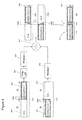
- Authority
- EP
- European Patent Office
- Prior art keywords
- overlapping
- transmit
- frequency
- radar
- received
- Prior art date
- Legal status (The legal status is an assumption and is not a legal conclusion. Google has not performed a legal analysis and makes no representation as to the accuracy of the status listed.)
- Withdrawn
Links
- 230000007423 decrease Effects 0.000 claims description 9
- 230000035559 beat frequency Effects 0.000 description 22
- 238000000034 method Methods 0.000 description 13
- 238000001228 spectrum Methods 0.000 description 12
- 238000012545 processing Methods 0.000 description 10
- 238000012937 correction Methods 0.000 description 9
- 230000006870 function Effects 0.000 description 7
- 238000005070 sampling Methods 0.000 description 7
- 230000010363 phase shift Effects 0.000 description 5
- 238000005259 measurement Methods 0.000 description 4
- 230000003595 spectral effect Effects 0.000 description 4
- 230000001052 transient effect Effects 0.000 description 4
- 238000006243 chemical reaction Methods 0.000 description 3
- 230000003111 delayed effect Effects 0.000 description 3
- 230000001419 dependent effect Effects 0.000 description 3
- 230000001066 destructive effect Effects 0.000 description 3
- 210000003195 fascia Anatomy 0.000 description 3
- 230000000630 rising effect Effects 0.000 description 3
- 230000009466 transformation Effects 0.000 description 3
- 230000005540 biological transmission Effects 0.000 description 2
- 230000001427 coherent effect Effects 0.000 description 2
- 238000004519 manufacturing process Methods 0.000 description 2
- 238000012986 modification Methods 0.000 description 2
- 230000004048 modification Effects 0.000 description 2
- 230000004044 response Effects 0.000 description 2
- 230000002238 attenuated effect Effects 0.000 description 1
- 230000006399 behavior Effects 0.000 description 1
- 230000015572 biosynthetic process Effects 0.000 description 1
- 238000004364 calculation method Methods 0.000 description 1
- 230000008859 change Effects 0.000 description 1
- 230000008878 coupling Effects 0.000 description 1
- 238000010168 coupling process Methods 0.000 description 1
- 238000005859 coupling reaction Methods 0.000 description 1
- 230000003247 decreasing effect Effects 0.000 description 1
- 238000009795 derivation Methods 0.000 description 1
- 230000002349 favourable effect Effects 0.000 description 1
- 238000001914 filtration Methods 0.000 description 1
- 238000005286 illumination Methods 0.000 description 1
- 230000008569 process Effects 0.000 description 1
- 238000012360 testing method Methods 0.000 description 1
Images




Classifications
-
- G—PHYSICS
- G01—MEASURING; TESTING
- G01S—RADIO DIRECTION-FINDING; RADIO NAVIGATION; DETERMINING DISTANCE OR VELOCITY BY USE OF RADIO WAVES; LOCATING OR PRESENCE-DETECTING BY USE OF THE REFLECTION OR RERADIATION OF RADIO WAVES; ANALOGOUS ARRANGEMENTS USING OTHER WAVES
- G01S13/00—Systems using the reflection or reradiation of radio waves, e.g. radar systems; Analogous systems using reflection or reradiation of waves whose nature or wavelength is irrelevant or unspecified
- G01S13/02—Systems using reflection of radio waves, e.g. primary radar systems; Analogous systems
- G01S13/06—Systems determining position data of a target
- G01S13/08—Systems for measuring distance only
- G01S13/10—Systems for measuring distance only using transmission of interrupted, pulse modulated waves
- G01S13/30—Systems for measuring distance only using transmission of interrupted, pulse modulated waves using more than one pulse per radar period
-
- G—PHYSICS
- G01—MEASURING; TESTING
- G01S—RADIO DIRECTION-FINDING; RADIO NAVIGATION; DETERMINING DISTANCE OR VELOCITY BY USE OF RADIO WAVES; LOCATING OR PRESENCE-DETECTING BY USE OF THE REFLECTION OR RERADIATION OF RADIO WAVES; ANALOGOUS ARRANGEMENTS USING OTHER WAVES
- G01S13/00—Systems using the reflection or reradiation of radio waves, e.g. radar systems; Analogous systems using reflection or reradiation of waves whose nature or wavelength is irrelevant or unspecified
- G01S13/02—Systems using reflection of radio waves, e.g. primary radar systems; Analogous systems
- G01S13/06—Systems determining position data of a target
- G01S13/08—Systems for measuring distance only
- G01S13/10—Systems for measuring distance only using transmission of interrupted, pulse modulated waves
- G01S13/26—Systems for measuring distance only using transmission of interrupted, pulse modulated waves wherein the transmitted pulses use a frequency- or phase-modulated carrier wave
-
- G—PHYSICS
- G01—MEASURING; TESTING
- G01S—RADIO DIRECTION-FINDING; RADIO NAVIGATION; DETERMINING DISTANCE OR VELOCITY BY USE OF RADIO WAVES; LOCATING OR PRESENCE-DETECTING BY USE OF THE REFLECTION OR RERADIATION OF RADIO WAVES; ANALOGOUS ARRANGEMENTS USING OTHER WAVES
- G01S7/00—Details of systems according to groups G01S13/00, G01S15/00, G01S17/00
- G01S7/02—Details of systems according to groups G01S13/00, G01S15/00, G01S17/00 of systems according to group G01S13/00
- G01S7/35—Details of non-pulse systems
- G01S7/352—Receivers
- G01S7/354—Extracting wanted echo-signals
-
- G—PHYSICS
- G01—MEASURING; TESTING
- G01S—RADIO DIRECTION-FINDING; RADIO NAVIGATION; DETERMINING DISTANCE OR VELOCITY BY USE OF RADIO WAVES; LOCATING OR PRESENCE-DETECTING BY USE OF THE REFLECTION OR RERADIATION OF RADIO WAVES; ANALOGOUS ARRANGEMENTS USING OTHER WAVES
- G01S13/00—Systems using the reflection or reradiation of radio waves, e.g. radar systems; Analogous systems using reflection or reradiation of waves whose nature or wavelength is irrelevant or unspecified
- G01S13/02—Systems using reflection of radio waves, e.g. primary radar systems; Analogous systems
- G01S13/06—Systems determining position data of a target
- G01S13/08—Systems for measuring distance only
- G01S13/32—Systems for measuring distance only using transmission of continuous waves, whether amplitude-, frequency-, or phase-modulated, or unmodulated
- G01S13/34—Systems for measuring distance only using transmission of continuous waves, whether amplitude-, frequency-, or phase-modulated, or unmodulated using transmission of continuous, frequency-modulated waves while heterodyning the received signal, or a signal derived therefrom, with a locally-generated signal related to the contemporaneously transmitted signal
- G01S13/343—Systems for measuring distance only using transmission of continuous waves, whether amplitude-, frequency-, or phase-modulated, or unmodulated using transmission of continuous, frequency-modulated waves while heterodyning the received signal, or a signal derived therefrom, with a locally-generated signal related to the contemporaneously transmitted signal using sawtooth modulation
-
- G—PHYSICS
- G01—MEASURING; TESTING
- G01S—RADIO DIRECTION-FINDING; RADIO NAVIGATION; DETERMINING DISTANCE OR VELOCITY BY USE OF RADIO WAVES; LOCATING OR PRESENCE-DETECTING BY USE OF THE REFLECTION OR RERADIATION OF RADIO WAVES; ANALOGOUS ARRANGEMENTS USING OTHER WAVES
- G01S13/00—Systems using the reflection or reradiation of radio waves, e.g. radar systems; Analogous systems using reflection or reradiation of waves whose nature or wavelength is irrelevant or unspecified
- G01S13/02—Systems using reflection of radio waves, e.g. primary radar systems; Analogous systems
- G01S13/06—Systems determining position data of a target
- G01S13/08—Systems for measuring distance only
- G01S13/32—Systems for measuring distance only using transmission of continuous waves, whether amplitude-, frequency-, or phase-modulated, or unmodulated
- G01S13/34—Systems for measuring distance only using transmission of continuous waves, whether amplitude-, frequency-, or phase-modulated, or unmodulated using transmission of continuous, frequency-modulated waves while heterodyning the received signal, or a signal derived therefrom, with a locally-generated signal related to the contemporaneously transmitted signal
- G01S13/345—Systems for measuring distance only using transmission of continuous waves, whether amplitude-, frequency-, or phase-modulated, or unmodulated using transmission of continuous, frequency-modulated waves while heterodyning the received signal, or a signal derived therefrom, with a locally-generated signal related to the contemporaneously transmitted signal using triangular modulation
-
- G—PHYSICS
- G01—MEASURING; TESTING
- G01S—RADIO DIRECTION-FINDING; RADIO NAVIGATION; DETERMINING DISTANCE OR VELOCITY BY USE OF RADIO WAVES; LOCATING OR PRESENCE-DETECTING BY USE OF THE REFLECTION OR RERADIATION OF RADIO WAVES; ANALOGOUS ARRANGEMENTS USING OTHER WAVES
- G01S13/00—Systems using the reflection or reradiation of radio waves, e.g. radar systems; Analogous systems using reflection or reradiation of waves whose nature or wavelength is irrelevant or unspecified
- G01S13/02—Systems using reflection of radio waves, e.g. primary radar systems; Analogous systems
- G01S13/06—Systems determining position data of a target
- G01S13/08—Systems for measuring distance only
- G01S13/32—Systems for measuring distance only using transmission of continuous waves, whether amplitude-, frequency-, or phase-modulated, or unmodulated
- G01S13/34—Systems for measuring distance only using transmission of continuous waves, whether amplitude-, frequency-, or phase-modulated, or unmodulated using transmission of continuous, frequency-modulated waves while heterodyning the received signal, or a signal derived therefrom, with a locally-generated signal related to the contemporaneously transmitted signal
- G01S13/347—Systems for measuring distance only using transmission of continuous waves, whether amplitude-, frequency-, or phase-modulated, or unmodulated using transmission of continuous, frequency-modulated waves while heterodyning the received signal, or a signal derived therefrom, with a locally-generated signal related to the contemporaneously transmitted signal using more than one modulation frequency
-
- G—PHYSICS
- G01—MEASURING; TESTING
- G01S—RADIO DIRECTION-FINDING; RADIO NAVIGATION; DETERMINING DISTANCE OR VELOCITY BY USE OF RADIO WAVES; LOCATING OR PRESENCE-DETECTING BY USE OF THE REFLECTION OR RERADIATION OF RADIO WAVES; ANALOGOUS ARRANGEMENTS USING OTHER WAVES
- G01S13/00—Systems using the reflection or reradiation of radio waves, e.g. radar systems; Analogous systems using reflection or reradiation of waves whose nature or wavelength is irrelevant or unspecified
- G01S13/02—Systems using reflection of radio waves, e.g. primary radar systems; Analogous systems
- G01S13/50—Systems of measurement based on relative movement of target
- G01S13/58—Velocity or trajectory determination systems; Sense-of-movement determination systems
- G01S13/583—Velocity or trajectory determination systems; Sense-of-movement determination systems using transmission of continuous unmodulated waves, amplitude-, frequency-, or phase-modulated waves and based upon the Doppler effect resulting from movement of targets
- G01S13/584—Velocity or trajectory determination systems; Sense-of-movement determination systems using transmission of continuous unmodulated waves, amplitude-, frequency-, or phase-modulated waves and based upon the Doppler effect resulting from movement of targets adapted for simultaneous range and velocity measurements
-
- G—PHYSICS
- G01—MEASURING; TESTING
- G01S—RADIO DIRECTION-FINDING; RADIO NAVIGATION; DETERMINING DISTANCE OR VELOCITY BY USE OF RADIO WAVES; LOCATING OR PRESENCE-DETECTING BY USE OF THE REFLECTION OR RERADIATION OF RADIO WAVES; ANALOGOUS ARRANGEMENTS USING OTHER WAVES
- G01S13/00—Systems using the reflection or reradiation of radio waves, e.g. radar systems; Analogous systems using reflection or reradiation of waves whose nature or wavelength is irrelevant or unspecified
- G01S13/88—Radar or analogous systems specially adapted for specific applications
- G01S13/93—Radar or analogous systems specially adapted for specific applications for anti-collision purposes
- G01S13/931—Radar or analogous systems specially adapted for specific applications for anti-collision purposes of land vehicles
-
- G—PHYSICS
- G01—MEASURING; TESTING
- G01S—RADIO DIRECTION-FINDING; RADIO NAVIGATION; DETERMINING DISTANCE OR VELOCITY BY USE OF RADIO WAVES; LOCATING OR PRESENCE-DETECTING BY USE OF THE REFLECTION OR RERADIATION OF RADIO WAVES; ANALOGOUS ARRANGEMENTS USING OTHER WAVES
- G01S13/00—Systems using the reflection or reradiation of radio waves, e.g. radar systems; Analogous systems using reflection or reradiation of waves whose nature or wavelength is irrelevant or unspecified
- G01S13/88—Radar or analogous systems specially adapted for specific applications
- G01S13/93—Radar or analogous systems specially adapted for specific applications for anti-collision purposes
- G01S13/931—Radar or analogous systems specially adapted for specific applications for anti-collision purposes of land vehicles
- G01S2013/9314—Parking operations
-
- G—PHYSICS
- G01—MEASURING; TESTING
- G01S—RADIO DIRECTION-FINDING; RADIO NAVIGATION; DETERMINING DISTANCE OR VELOCITY BY USE OF RADIO WAVES; LOCATING OR PRESENCE-DETECTING BY USE OF THE REFLECTION OR RERADIATION OF RADIO WAVES; ANALOGOUS ARRANGEMENTS USING OTHER WAVES
- G01S13/00—Systems using the reflection or reradiation of radio waves, e.g. radar systems; Analogous systems using reflection or reradiation of waves whose nature or wavelength is irrelevant or unspecified
- G01S13/88—Radar or analogous systems specially adapted for specific applications
- G01S13/93—Radar or analogous systems specially adapted for specific applications for anti-collision purposes
- G01S13/931—Radar or analogous systems specially adapted for specific applications for anti-collision purposes of land vehicles
- G01S2013/9321—Velocity regulation, e.g. cruise control
-
- G—PHYSICS
- G01—MEASURING; TESTING
- G01S—RADIO DIRECTION-FINDING; RADIO NAVIGATION; DETERMINING DISTANCE OR VELOCITY BY USE OF RADIO WAVES; LOCATING OR PRESENCE-DETECTING BY USE OF THE REFLECTION OR RERADIATION OF RADIO WAVES; ANALOGOUS ARRANGEMENTS USING OTHER WAVES
- G01S7/00—Details of systems according to groups G01S13/00, G01S15/00, G01S17/00
- G01S7/02—Details of systems according to groups G01S13/00, G01S15/00, G01S17/00 of systems according to group G01S13/00
- G01S7/35—Details of non-pulse systems
- G01S7/352—Receivers
- G01S7/356—Receivers involving particularities of FFT processing
Definitions
- the present disclosure relates to radar systems, including radar systems that can be used to determine a distance to a reflecting object in automotive applications.
- Automotive radar systems can increase road safety and driver comfort.
- the first generation of automotive radar systems targeted automatic cruise control and parking aid applications.
- a radar system comprising:
- the transmitter controller is configured to operate the oscillator in the first-operating-mode to provide the first-ramp-frequency-portion of the transmit-radar-signal.
- the transmitter controller may be configured to operate the oscillator in the second-operating-mode to provide the second-ramp-frequency-portion of the transmit-radar-signal.
- the receiver controller in order to provide the combined-overlapping-portion, is configured to:
- the receiver controller is configured to combine the windowed-first-overlapping-portion with the windowed-second-overlapping-portion by adding the windowed-first-overlapping-portion to the windowed-second-overlapping-portion.
- the receiver controller in order to provide the combined-overlapping-portion, is configured to:
- the receiver controller is configured to combine the windowed-settled-first-overlapping-portion with the windowed-settled-second-overlapping-portion by adding the windowed-settled-first-overlapping-portion to the windowed-settled-second-overlapping-portion.
- the receiver controller is configured to provide the combined-first-portion by multiplying together the transmit-first-non-overlapping-portion and the received-first-non-overlapping-portion.
- the receiver controller is configured to provide the combined-first-portion by multiplying together the transmit-first-non-overlapping-portion and the received-first-non-overlapping-portion, and removing an unsettled-portion from the result of the multiplication.
- the receiver controller is configured to provide the combined-second-portion by multiplying together the transmit-second-non-overlapping-portion and the received-second-non-overlapping-portion.
- the transmitter controller is configured to reconfigure the oscillator from the first-operating-mode to the second-operating-mode during the transmit-first-constant-frequency-portion.
- the transmitter controller is configured to set the duration of the transmit-first-constant-frequency-portion such that it is at least as long as the time difference between the transmit-radar-signal and the received-radar-signal. This time difference may be referred to as a time-of-flight.
- the transmit-radar-signal may comprises a plurality of chirps.
- Each chirp may comprise (i) a transmit-first-ramp-frequency-portion, (ii) a transmit-first-returning-frequency-portion, (iii) a transmit-second-ramp-frequency-portion, and (iv) a transmit-second-returning-frequency-portion.
- the receiver controller is further configured to determine a distance to a reflecting object based on the output signal.
- an integrated circuit comprising any radar system disclosed herein.
- an automotive radar system comprising any radar system disclosed herein or any IC disclosed herein.
- Automotive parking assist systems can be based upon ultra-sonic and/or camera sensors.
- Car manufacturers are seeking ways to replace the ultra-sonic sensors by radar sensors.
- Ultra-sonic sensors require openings in the car's fascia in order to let the sound waves pass. These openings can be aesthetically displeasing, and can be exposed to the weather and dirt. Furthermore, these sensors are painted in the same colour as the car's fascia, therefore the car manufacturer has to keep a supply of different sensors.
- Backwards facing cameras can also be used as a parking aid.
- a live view of the area behind the car is displayed in the car's centre console. This can require an expensive cabling solution.
- it can be difficult to accurately estimate the distance between the camera and the objects in front of the camera.
- a radar sensor can be mounted behind the car's fascia. As a consequence it is an aesthetically pleasing solution. Moreover, the radar sensor can be more reliable than an ultra-sonic sensor, because it is not exposed to weather influences and dirt.
- radar based parking systems An important requirement for radar based parking systems is an extremely high distance resolution. Due to practical limitations, known radar systems may not be able to provide a satisfactory distance resolution. For example, radar based parking applications require wide bandwidth waveforms that are difficult to realize in a cost effective way. One or more embodiments disclosed herein can increase this bandwidth.
- FIG. 1 schematically shows a radar system 100. It comprises three main sections: a transmit section 110, a receive section 120 and a control and processing section 130. As will be discussed below, a transmit-radar-signal 102, modulated according to a specific waveform principle, is transmitted at a certain carrier frequency (for example 79 GHz).
- a transmit-radar-signal 102 modulated according to a specific waveform principle, is transmitted at a certain carrier frequency (for example 79 GHz).
- the transmit section 110 comprises a transmitter controller 111, which may also be referred to as a high-frequency chirp generator.
- the transmitter controller 111 controls an oscillator, which in this example comprises a phase locked loop (PLL) 112.
- PLL 112 is controlled such that it produces a frequency modulated continuous wave (FMCW), which will be referred to as a transmit-radar-signal 102.
- FMCW frequency modulated continuous wave
- the transmit-radar-signal 102 is amplified by a power amplifier 114, and fed, via an antenna output connector (not shown), to a transmit aerial or antenna (not shown) for transmission as a radar signal.
- a received-radar-signal 104 is received by one or more receive aerials or antenna (not shown), and input via one or more antenna input connectors to the receive section 120.
- receive aerials or antenna not shown
- antenna input connectors to the receive section 120.
- one receiver is shown, although it will be appreciated that the system may comprise a different number of receivers, such as two or three or more.
- the received-radar-signal 104 is amplified by a low noise amplifier 125 and down-converted by a mixer 124 that mixes the received-radar-signal 104 with a copy of the transmit-radar-signal 141.
- the down-converted signal provided at the output of the mixer 124 is filtered by a high pass filter 121, amplified by a variable gain amplifier 123 and then filtered by a low pass filter 127.
- the signal output of the low pass filter 127 may be referred to as an intermediate-frequency (IF) signal 106, and is digitised by an analogue-to-digital converter (ADC) 122.
- IF intermediate-frequency
- ADC analogue-to-digital converter
- the output terminal of the ADC 122 is processed by a sample rate converter 128 and then provided as an input to a digital signal processor 131.
- the digital signal processor (DSP) 131 is an example of a receiver controller, and forms part of the control and processing section 130.
- the control and processing section 130 also includes a program memory 132 and a data memory 133.
- the output from the radar system may be communicated with other electronics within the automobile using a system interface 160 such as a controller area network (CAN) bus.
- CAN controller area network
- a signal, modulated according to a specific waveform principle is transmitted at a predetermined carrier frequency.
- the reflected signals are down-converted to baseband signals by the analogue receiver and processed by the digital part of the system.
- one or more of the distance to an object, the relative radial velocity, that is to say, the velocity at which the object is approaching the car, and the angle between the object and the car are calculated.
- FMCW frequency modulated continuous wave
- automotive radar systems due to its accuracy and robustness.
- implementation in which a sequence of short duration frequency chirps is transmitted can have favourable properties, for detecting objects moving with a non-zero relative radial velocity.
- the radial distance to a reflecting object is converted to a sine wave oscillating at a beat frequency determined by the slope of the frequency ramp and the time of flight to the object. It is up to the digital baseband to estimate the frequency of the sine wave; in some implementations this may be done by a Fast Fourier Transformation (FFT).
- FFT Fast Fourier Transformation
- FIG. 2 shows an FMCW chirp sequence of N frequency ramps in a transmit-radar signal 202, and a received-radar-signal 204.
- Instantaneous frequency is shown on the vertical axis in figure 2
- time is shown on the horizontal axis.
- the frequency of each chirp varies between a carrier frequency (fc) 206 and a maximum frequency (fmax) 208.
- Each chirp has a duration of T chirp , and ramp-period T ramp during which the frequency of the chirp increases. It will be appreciated that in some examples, a ramp-period during which the frequency of the chirp decreases can be used.
- the difference between the carrier frequency (fc) 206 and the maximum frequency (fmax) 208 is the bandwidth of the ramp / chirp ( ⁇ f), and can be limited by the performance of the PLL.
- the frequency range of the PLL may be set by selection of one of a plurality of hardware configurations that is suitable for a frequency spectrum that is assigned to the radar system.
- the bandwidth of the chirp ( ⁇ f) can be limited by the bandwidth of the hardware configuration that is in use.
- the received-radar-signal 204 is delayed in time with respect to the transmit-radar signal 202.
- the time delay is due to the propagation time between the radar system and the reflecting object in the forward and backward direction.
- a sine wave with an increasing or decreasing frequency is transmitted, as indicated by the slopes of the frequency-domain plots of the transmit-radar signal 202 and the received-radar-signal 204.
- the instantaneous frequency difference between the transmit-radar signal 202 and the received-radar-signal 204 is constant for at least part of the duration of a frequency ramp.
- the transmit-radar signal 202 is mixed with the received-radar-signal 204 (which is a time delayed version of the transmit-radar signal 202).
- the received-radar-signal 204 is an attenuated, time delayed, and phase rotated version of the transmit-radar signal 202.
- the result of the down-conversion and subsequent low pass filtering operations is a sine wave that oscillates at the beat frequency.
- the corresponding Doppler frequency is added to the beat frequency.
- the duration of the chirp is very short, for example shorter than 100 us, and the frequency deviation is at least several tens of MHz.
- the Doppler frequency is very small compared to the beat frequency and can be ignored in the calculation of the distance.
- the Doppler component will, however, change the phase of the received frequency ramp.
- a well-known technique, the two dimensional Fast Fourier Transformation (FFT) is used to calculate the relative radial velocity. This technique is further explained below with reference to figure 7 .
- the relation between the distance and the beat frequency is linear.
- the beat frequency increases with increasing distance to the reflecting object.
- multiple reflections can be present in the field of view of the radar system.
- the output of the down-conversion operation is a summation of sine waves oscillating at the beat frequencies corresponding to the distances to the reflecting objects.
- the illumination of two reflecting objects in the radar's field of view results in an IF (intermediate frequency) signal at the input of the ADC that consists of the summation of two sine waves oscillating at their respective beat frequencies.
- the resolution of the radar system defines how close these two objects can be located while still being perceived by the radar system as two separate objects.
- FMCW radar system terminology the first zero crossing bandwidth of the frequency domain response is used as a measure of the resolution. The relationship between this bandwidth and resolution in meters will be explained below.
- the zero crossing bandwidth is equal to the inverse of T FFT , where T FFT is the duration of the acquisition interval in each frequency ramp.
- T FFT is the duration of the acquisition interval in each frequency ramp.
- ⁇ f beat ⁇ f tramp ⁇ ⁇
- D RES T ramp T FFT c 0 2 ⁇ f
- Figures 3a , 3b and 3c all show an example embodiment of a transmit-radar-signal 302, a received-radar-signal 304, and an intermediate-frequency (IF) signal 306.
- the transmit-radar-signal 302 can be provided by the PLL of figure 1 .
- the received-radar-signal 304 can be received by the receive section of figure 1 .
- the IF signal 306 can be provided to the ADC of figure 1 . In this way, the IF signal 306 is a filtered version of the product of the transmit-radar-signal 302 and the received-radar-signal 304.
- Features of the transmit-radar-signal 302 are labelled in figure 3a .
- Features of the received-radar-signal 304 are labelled in figure 3b .
- Figure 3c is mainly used to discuss overlapping portions of the transmit-radar-signal 302 and the received-radar-signal 304.
- the time delay between the transmit-radar-signal 302 and the received-radar-signal 304 is shown in figures 3a - 3c with the symbol ⁇ 311 and represents the time of flight of the radar signal to and from the reflecting object.
- the transmit-radar-signal 302 includes two sub-ramps, which will be referred to as a transmit-first-rising-frequency-portion 307 and a transmit-second rising-frequency-portion 308.
- the frequency of the transmit-radar-signal 302 increases over time during both of these portions. It can be seen that the frequency of the transmit-first-rising-frequency-portion 307 starts at the carrier frequency, and stops rising when the frequency has increased by ⁇ f.
- ⁇ f is a limitation that is imposed by the hardware of the PLL.
- the high-frequency chirp generator reconfigures the PLL from a first-operating-mode to second-operating-mode, for example so that the PLL utilises a different hardware configuration.
- the transmit-second rising-frequency-portion 308 increases the frequency by a further amount equal to ⁇ f.
- D RES distance resolution
- the PLL is operated in the first-operating-mode to provide the first rising-frequency-portion 307 of the transmit-radar-signal 302, and is operated in the second-operating-mode to provide the second rising-frequency-portion 308 of the transmit-radar-signal 302. Therefore, a second frequency ramp can be used that has a frequency deviation that does not fit in the sweep bandwidth of the waveform generator PLL when it is in the first-operating-mode.
- the frequency ranges of the transmit-first-rising-frequency-portion 307 and the transmit-second rising-frequency-portion 308 can be controlled such that they overlap.
- the overlapping portions can then be processed such that any phase distortions between the end of the transmit-first-rising-frequency-portion 307 and the start of the transmit-second rising-frequency-portion 308 can be reduced.
- the transmit-radar-signal 302 of figure 3 includes the following portions:
- the PLL is reconfigured after the transmit-first-falling-frequency portion 309.
- the substantially constant portion 310 can also be referred to as T switch .
- the starting frequency of the transmit-second rising-frequency-portion 308 is less than the end frequency of the transmit-first-rising-frequency-portion 307. This results in an overlap in the frequency ranges of the transmit-first-rising-frequency-portion 307 and the transmit-second rising-frequency-portion 308. This overlap in frequency range is shown in figure 3a as F shift 313.
- the overlapping frequency range corresponds to a transmit-first-overlapping-portion 315 in the transmit-first-rising-frequency-portion 307, and a transmit-second-overlapping-portion 316 in the transmit-second-rising-frequency-portion 308. Therefore, the transmit-first-rising-frequency-portion 307 also includes a transmit-first-non-overlapping-portion 314; and the transmit-second-rising-frequency-portion 308 also includes a transmit-second-non-overlapping-portion 317.
- the frequency range of the transmit-first-overlapping-portion 315 corresponds to the frequency range of the transmit-second-frequency-overlapping-portion 316.
- the frequency range of the transmit-first-non-overlapping-portion 314 is less than that of the transmit-first-overlapping-portion 315.
- the frequency range of the transmit-second-non-overlapping-portion 317 is greater than that of the transmit-second-overlapping-portion 316.
- the transmit-second-falling-frequency portion 312 enables the instantaneous frequency of the chirp to return to the carrier frequency (f c ) for the start of the next chirp, and can be considered as a reset phase.
- the PLL is reconfigured back to the first operating mode.
- the received-radar-signal 304 includes similar portions to the transmit-radar-signal 302. More particularly, the received-radar-signal 304 includes:
- the received-radar-signal 304 includes a received-first-non-overlapping-portion 323 and a received-first-overlapping-portion 324.
- the received-second-rising-frequency-portion 321 includes a received-second-overlapping-portion 325 and a received-second-non-overlapping-portion 326. Each of these portions is defined as being received at a time that corresponds to the equivalently named portions of the transmit-radar signal 302.
- the IF signal 306 is the product of the transmit-radar-signal 302 and the received-radar-signal 304.
- a settling-portion (T settle ) 331 occurs at the start of the chirp.
- the IF signal 306 is building up to its beat-frequency level (f beat ) 324 during the settling-portion 331, whilst the frequencies of the transmit-radar-signal 302 and the received-radar-signal 304 increase from the zero frequency level.
- This settling-portion (T settle ) 331 of the IF signal 306 is an example of an unsettled-portion, which is excluded from a first acquisition interval 335.
- a first acquisition interval 335 starts when the IF signal 306 reaches its beat-frequency level 324, after the initial settling time has expired. Once the IF signal 306 has reached its beat frequency, it can be said to have reached a settled frequency value. As is known in the art, the DSP can determine that an initial settling time has expired, and that the signal is "back at the receiver” within a given time (based upon the maximum distance of the radar). The PLL may also need some time to settle to linear behaviour. In some examples a few micro-seconds can be reserved for this processing. The precise timing can be generated by a timing generator inside the radar. The first acquisition interval 335 then continues until the transmit-radar-signal 302 starts falling (the transmit-first-falling-frequency portion 309).
- the duration of the first acquisition interval 335 can be referred to as T FFT .
- T FFT The duration of the transmit-radar-signal 302 is falling and the received-radar-signal 304 is still rising, there will not be a constant difference between the frequency levels of the two signals, and therefore the IF signal 306 is no longer representative of the distance to the reflected object in the same way as it was before.
- the duration of the transmit-first-falling-frequency portion 309 can be set such that there is a sufficient overlap in frequency between the transmit-radar-signal 302 and the received-radar-signal 304 to enable the overlapping portions to be combined in an acceptable way, as will be described in more detail below with reference to figure 4 .
- a combined-first-portion 337 of the IF signal 306 is provided, which includes a combination of the transmit-first-non-overlapping-portion 314 and the received-first-non-overlapping-portion 323.
- the combined-first-portion 337 includes the result of multiplying (using the mixer of figure 1 , for example) together the transmit-first-non-overlapping-portion 314 and the received-first-non-overlapping-portion 323, and removing an unsettled-portion 331 from the result of the multiplication.
- the first acquisition interval 335 includes a combination of part of the transmit-first-overlapping-portion 315 and a part of the received-first-overlapping-portion 324.
- the first acquisition interval 335 includes a combination of a first-portion 333 of the transmit-first-overlapping-portion 315 that has the same frequency range as an unsettled-transmit-second-overlapping-portion 332 (as described below), and the part of the received-first-overlapping-portion 324 that is received at the same time that the first-portion 333 is transmitted.
- the transmit-radar-signal 302 After the transmit-first-falling-frequency portion 309, the transmit-radar-signal 302 then begins the transmit-first-constant-frequency portion 310.
- the duration of the transmit-first-constant-frequency portion 310 can be at least as long as the time-of-flight ⁇ 311 of the radar signal. In this example, the duration of the transmit-first-constant-frequency portion 310 is the same as the time-of-flight ⁇ 311.
- the received-radar-signal 304 falls to the constant value just as the transmit-radar-signal 302 leaves the same constant value.
- the beat frequency of the IF signal is zero because the frequency of the received-radar-signal 304 is the same as the frequency of the transmit-radar-signal 302.
- the transmit-second-overlapping-portion 316 begins at the start of the transmit-second rising-frequency-portion 308 and ends a period of time after the settling-portion (T settle ) has finished. That is, the transmit-second-overlapping-portion 316 and the settling-portion (T settle ) 332 start at the same time, but the transmit-second-overlapping-portion 316 is longer than the settling-portion (T settle ) 332.
- the transmit-second-overlapping-portion 316 can be comprised of: a settled-transmit-second-overlapping-portion 328a and an unsettled-transmit-second-overlapping-portion 332.
- the received-second-overlapping-portion 325 can similarly include a settled-received-second-overlapping-portion that occurs at the same time as the corresponding settled-transmit-second-overlapping-portion.
- a combined-second-portion 338 of the IF signal 306 is provided, which includes a combination of the transmit-second-non-overlapping-portion 317 and the received-second-non-overlapping-portion 326.
- the combined-second-portion 338 includes the result of multiplying (using the mixer of figure 1 , for example) together the transmit-second-non-overlapping-portion 317 and the received-second-non-overlapping-portion 326
- the transmit-first-overlapping-portion 315 can be said to have a settled-transmit-first-overlapping-portion 329a, which corresponds to the same frequency range as the settled-transmit-second-overlapping-portion 328a.
- the remainder of the transmit-first-overlapping-portion 315 however is not unsettled.
- the first acquisition interval 335 ends with a settled-transmit-first-overlapping-portion 329a
- the second acquisition interval 327 has a settled-transmit-second-overlapping-portion 328a at its start (which is not at the start of the received-second-rising-frequency-portion 321 because of the settling portion T settle ).
- the settled-transmit-first-overlapping-portion 329a and the settled-transmit-second-overlapping-portion 328a of the transmit-radar signal 302 have the same frequency range.
- the received-first-rising-frequency-portion 318 defines a settled-received-first-overlapping-portion 329b.
- the received-second-rising-frequency-portion 321 defines a settled-received-second-overlapping-portion 328b.
- the IF signal 306, includes a settled-first-overlapping-portion 329c, which is the product of the settled-transmit-first-overlapping-portion 329a and the settled-received-first-overlapping-portion 329b.
- the settled-first-overlapping-portion 329c of the IF signal 306 corresponds to the same period of time (shown with reference 329 in figure 3c ) as the settled-transmit-first-overlapping-portion 329a and the settled-received-first-overlapping-portion 329b.
- the settled-first-overlapping-portion 329c of the IF signal 306 corresponds to the transmit-radar-signal 302 having a first-settled-frequency-range (settled 334).
- the IF signal 306 includes a settled-second-overlapping-portion 328c, which is the product of the settled-transmit-second-overlapping-portion 328a and the settled-received-second-overlapping-portion 328b.
- the settled-second-overlapping-portion 328c of the IF signal 306 corresponds to the same period of time (shown with reference 328 in figure 3c ) as the settled-transmit-second-overlapping-portion 328a and the settled-received-second-overlapping-portion 328b.
- the settled-second-overlapping-portion 328c of the IF signal 306 corresponds to the transmit-radar-signal 302 having a second-settled-frequency-range (F settled 334), which is the same as the first-settled-frequency-ranges.
- the transmit-first-rising-frequency-portion is an example of a transmit-first-ramp-frequency-portion.
- the frequency of the transmit-radar-signal either increases or decreases over time. Therefore, all other portions that are described herein as rising-frequency-portions can be considered as examples of ramp-frequency-portions, during which the frequency changes in the same way as the transmit-first-ramp-frequency-portion.
- all portions that are described herein as falling-frequency-portions can be considered as examples of returning-frequency-portions, during which the frequency changes in the opposite way to the transmit-first-ramp-frequency-portion.
- the transmit-radar-signal 302 in this example includes a plurality of chirps, where each chirp includes (i) the transmit-first-rising-frequency-portion 307, (ii) the transmit-first-falling-frequency-portion 309, (iii) the transmit-first-constant-frequency portion 310, (iv) the transmit-second-rising-frequency-portion 308, and (v) the transmit-second-falling-frequency-portion 312.
- the received-radar-signal 304 includes a plurality of chirps, where each chirp includes (i) the received-first-rising-frequency-portion 318, (ii) the received-first-falling-frequency-portion 319, (iii) the received-first-constant-frequency portion 320, (iv) the received-second-rising-frequency-portion 321, and (v) the received-second-falling-frequency-portion 322.
- a combined-overlapping-portion can be determined based on a combination of the settled-transmit-first-overlapping-portion 329a, the settled-received-first-overlapping-portion 329b, the settled-transmit-second-overlapping-portion 328a, and the settled-received-second-overlapping-portion 328b.
- two sets of samples are available for the combined ramp.
- the two sets of samples correspond to a FMCW frequency ramp of nearly twice the bandwidth ( ⁇ f) that can be provided by a single configuration of the PLL.
- ⁇ f bandwidth
- phase discontinuity can distort the frequency spectrum of the combined sampling intervals.
- the transmit-first-falling-frequency portion 309 (which may be referred to as a reset phase)
- the instantaneous frequency of the transmitted frequency ramp is lowered by F shift and remains constant for at least ⁇ seconds. Therefore the phase of the IF signal 306 is equal to 2 ⁇ ( f c + ⁇ F - F shift ) ⁇ after ⁇ seconds. After the constant frequency period the transmitted frequency increases once more.
- phase discontinuity is distance dependent as it depends on the time of flight. In a FMCW system this dependency is translated to frequency.
- F shift ⁇ f T ramp T settle .
- small deviations might occur due to transients in the receiver and transmitter chain. These transients could cause amplitude and small phase jumps between the end of the first acquisition interval and the start of the second acquisition interval.
- the magnitude of the frequency spectrum of each (zero padded) acquisition interval is equal.
- the phase of the spectrum of the second acquisition interval is shifted compared to the phase of the spectrum of the first interval. This phase shift is due to the time shift of the second interval and different start frequency.
- this phase shift depends on the duration of the acquisition interval and the frequencies at which the spectrum is evaluated. If both spectra would be added together, then they would add coherently at some frequencies and destructively at other frequencies. In this case, the spectra add coherently at the peak amplitude of a spectrum corresponding to a single reflecting object.
- the spectrum of the first and second acquisition interval are X 1 (n) and X 2 (n) respectively.
- the frequency shift F shift 313 can cause a phase discontinuity between the end of the first acquisition interval 335 and the start of the second acquisition interval 327. That is, in the scenario described above, the desired coherent and destructive addition pattern is lost. It has been found that simply combining the first acquisition interval 335 and the second acquisition interval 327 without correction can result in loss of resolution, and formation of undesired ghost targets.
- phase discontinuity of equation 11 is distance dependent. That is, a first reflecting object causes a phase shift which is different from the phase shift caused by a second reflecting object, which is at a different distance to the radar than the first object. The distance is converted to a beat frequency in a FMCW system. Thus the linear phase relationship of equation 11 is converted into a linear phase shift over beat frequency in the frequency domain.
- figure 3 relates to an example embodiment that has two consecutive sub-ramps.
- the radar system can make use of a sequence of FMCW waveforms.
- Each frequency ramp consists of two consecutive frequency sub-ramps separated by a small time interval in which the PLL can be reconfigured.
- the instantaneous frequency of the second sub-ramp at the beginning of the second acquisition interval is close to the instantaneous frequency at the end of the first acquisition interval.
- the instantaneous frequency can be precisely controlled by a transmitter controller (which is an example of a waveform generator) and can be highly predictable.
- Figure 4 illustrates schematically an example embodiment of how samples from the first acquisition interval can be combined with signals from the second acquisition interval, in the time domain.
- the combination / correction technique can be applied in the frequency domain. This processing can be performed by the DSP of figure 1 , which is an example of a receiver controller.
- Figure 4 shows a first-data-block 442 that includes a first-sampling-interval-block 425.
- the first-sampling-interval-block 425 corresponds to samples that are taken from the IF signal during the first acquisition interval, as it is shown in figures 3a to 3c .
- Figure 4 also shows a second-data-block 443 that includes a second-sampling-interval-block 427.
- the second-sampling-interval-block 427 corresponds to samples that are taken from the IF signal during the second acquisition interval, as it is shown in figures 3a to 3c .
- the DSP has separated the first-sampling-interval-block 425 and the second-sampling-interval-block 427 from the IF signal and padded with blocks of zeros 440, 441 to form the first-data-block 442 and the second-data-block 443.
- Each of the blocks of zeros 440, 441 has the same length / duration (N) as the first-sampling-interval-block 425 and the second-sampling-interval-block 427.
- the first-sampling-interval-block 425 is padded by appending a first block of zeros 440.
- the second-sampling-interval-block 427 is padded by prepending a second block of zeros 441.
- the end of the first-sampling-interval-block 425 includes a settled-first-overlapping-portion 429c
- the start of the second-sampling-interval-block 427 includes a settled-second-overlapping-portion 428c.
- the DSP then applies a time shift operation 442 to the first-data-block 442 such that some of the first block of zeros 440 are removed.
- the duration of the number of zeros that are removed corresponds to the duration of the settled-first-overlapping-portion 429 and the settled-second-overlapping-portion 428.
- N overlap F shift - T settle ⁇ f T ramp T ramp ⁇ f F sample where F sample equals the sampling frequency of the ADC that is shown in figure 1 .
- the DSP then applies a first windowing operation 446 to the settled-first-overlapping-portion 429c of the IF signal to provide a windowed-settled-first-overlapping-portion 429d, and applies a second windowing operation 445 to the settled-second-overlapping-portion 428c of the IF signal to provide a windowed-settled-second-overlapping-portion 428d.
- a triangular windowing function is used.
- the output of the first windowing operation 446 is a processed-first-data-block 442a.
- the output of the second windowing operation 445 is a processed-second-data-block 443a.
- the DSP then combines, in this example adds together, the processed-first-data-block 442a and the processed-second-data-block 443a, which is shown schematically as an adder 447 in figure 4 .
- This adding operation results in an output signal 472 that includes:
- a distance to one or more reflecting objects can then be determined based on the output signal 472.
- the adding operation can be considered as adding the overlapping samples together, and appending the remaining samples of sampling interval 2 427 to the new sampling interval 1 425.
- further zero padding can applied to increase the length of the new acquisition interval to twice the length (N) of sampling interval 1 425.
- additional zeros 444 are included at the end of the processed-second-data-block 443a, after the first-sampling-interval-block 427.
- the new acquisition interval (the output of the adder 447) can then be processed as if it was a single frequency ramp.
- the DSP can apply additional windowing, for example using a Chebyshev window.
- the resultant windowed signal can then be transformed to the frequency domain by a FFT of twice the length of the first acquisition interval (N).
- a second FFT can be executed over multiple chirp signals to estimate the Doppler frequency as explained below with reference to figure 7 .
- the overlapping technique described above with reference figure 4 can reduce transient effects than can occur at the start of a new chirp.
- Figures 5a and 5b shows a plot of power on the vertical axis versus distance on the horizontal axis. Measurements are shown for a system tested with a single corner reflector at a distance of about 1.2m.
- Figure 5b shows a zoomed-in region of the plots at the distance of about 1.2m
- a first plot 552 shows the results for a 500MHz chirp, such as the one illustrated in figure 2 .
- a second plot 554 shows the results for two combined 500MHz chirps, such as the ones illustrated in figures 3a to 3c , but without the phase correction that is described with reference to figure 4 .
- a third plot 556 shows the results for two combined 500MHz chirps, such as the ones illustrated in figures 3a to 3c , with the phase correction that is described with reference to figure 4 .
- the second and third plots 554, 556 represent measurement result using two 500 MHz chirps to emulate a 1 GHz chirp. A 25.6 ⁇ s single acquisition interval was used, a Chebyshev window with 70 dB side lobes, and an effective chirp bandwidth of 420 MHz.
- Figure 5b also includes 3dB markers, which indicate that the resolution for the first plot 552 is 0.55m and the resolution for the third plot 556 is better, at 0.31 m. The corresponding resolution of a single 1 GHz chirp is 0.28 meters. Figure 5b also shows that the third plot 556 provides a more accurate indication of the distance to the corner reflector than the second plot 554.
- Figure 6 shows a plot of power on the vertical axis versus distance on the horizontal axis. Measurements are shown for a system tested with two corner reflectors in close proximity at 0.8 and 1.2 meters.
- a first plot 662 shows the results for a 500MHz chirp
- a second plot 664 shows the results for two combined 500MHz chirps without phase correction
- a third plot 666 shows the results for two combined 500MHz chirps with phase correction.
- the third plot 666 show two peaks (which correctly represent the two corner reflectors) whereas the uncorrected result of the second plot 664 shows a ghost, third, target. Furthermore, the first plot 662, which represents a single 500 MHz chirp, is not capable of resolving both reflectors.
- the two dimensional Fast Fourier Transformation can be used to calculate the relative radial velocity.
- FIG. 7 shows schematically a two dimensional FFT.
- each received chirp is converted to the frequency domain by means of a FFT operation and stored in a row by row fashion.
- a FFT operation is performed over all the samples in a single column. This operation is performed for all columns.
- One or more examples disclosed herein relate to a technique for improving distance resolution by means of concatenating multiple radar waveforms in a radar waveform generator.
- large bandwidth emulation for automotive radar systems can be provided by means of concatenation of multiple frequency ramps.
- a frequency modulated continuous waveform is described, which combines two frequency ramps with an offset in start frequency, into a single ramp with the goal of increasing the distance resolution.
- a distance dependent, linear phase correction term can applied to the samples corresponding to the second frequency ramp.
- This correction can be implemented by a time shift in time domain.
- the samples corresponding to the second ramp can then be partially overlapped with the last samples of the first ramp.
- the obtained vector can then be windowed and transformed to the frequency domain.
- Examples disclosed herein can address resolution limitations due to limited chirp bandwidth that can be caused by limitations of a Voltage Controlled Oscillator in a waveform generator PLL.
- the examples also address phase distortion, which can arise due to a concatenation of FMCW frequency ramps with equal frequency slope and duration but with different start frequencies. Small deviations in amplitude due to transients at the beginning and end of the chirp signal can also be addressed.
- a FMCW based radar system in which two or more frequency ramps are combined into a single frequency ramp with the goal of increasing the distance resolution of the radar system.
- a FMCW based radar system as disclosed herein can transmit a sequence of frequency ramps, wherein a single ramp is made up of multiple sub-ramps. Each of these multiple subs-ramps can have a starting frequency which is close to the frequency at which the previous sub ramp ended. In between the transmission of these multiple sub-ramps the PLL can switch between filter banks.
- a phase correction technique in the digital baseband of the radar system can be used to remove the phase discontinuity between two consecutive frequency sub-ramps.
- a technique in which the second transmitted frequency sub-ramp has a time interval at the beginning of its acquisition interval in which the instantaneous frequencies are equal to the instantaneous frequencies during a time interval at the end of the first sub-ramp.
- a digital signal processing technique can be used in which part of the last first chirp acquisition interval is added to a first part of the second term. The addition can be weighted by window functions.
- the set of instructions/method steps described above are implemented as functional and software instructions embodied as a set of executable instructions which are effected on a computer or machine which is programmed with and controlled by said executable instructions. Such instructions are loaded for execution on a processor (such as one or more CPUs).
- processor includes microprocessors, microcontrollers, processor modules or subsystems (including one or more microprocessors or microcontrollers), or other control or computing devices.
- a processor can refer to a single component or to plural components.
- the set of instructions/methods illustrated herein and data and instructions associated therewith are stored in respective storage devices, which are implemented as one or more non-transient machine or computer-readable or computer-usable storage media or mediums.
- Such computer-readable or computer usable storage medium or media is (are) considered to be part of an article (or article of manufacture).
- An article or article of manufacture can refer to any manufactured single component or multiple components.
- the non-transient machine or computer usable media or mediums as defined herein excludes signals, but such media or mediums may be capable of receiving and processing information from signals and/or other transient mediums.
- Example embodiments of the material discussed in this specification can be implemented in whole or in part through network, computer, or data based devices and/or services. These may include cloud, internet, intranet, mobile, desktop, processor, look-up table, microcontroller, consumer equipment, infrastructure, or other enabling devices and services. As may be used herein and in the claims, the following non-exclusive definitions are provided.
- one or more instructions or steps discussed herein are automated.
- the terms automated or automatically mean controlled operation of an apparatus, system, and/or process using computers and/or mechanical/electrical devices without the necessity of human intervention, observation, effort and/or decision.
- any components said to be coupled may be coupled or connected either directly or indirectly.
- additional components may be located between the two components that are said to be coupled.
Landscapes
- Engineering & Computer Science (AREA)
- Radar, Positioning & Navigation (AREA)
- Remote Sensing (AREA)
- Physics & Mathematics (AREA)
- Computer Networks & Wireless Communication (AREA)
- General Physics & Mathematics (AREA)
- Electromagnetism (AREA)
- Signal Processing (AREA)
- Radar Systems Or Details Thereof (AREA)
Priority Applications (5)
| Application Number | Priority Date | Filing Date | Title |
|---|---|---|---|
| EP15177911.3A EP3121619A1 (fr) | 2015-07-22 | 2015-07-22 | Système radar |
| US15/195,267 US10379210B2 (en) | 2015-07-22 | 2016-06-28 | Radar system and method that utilizes overlapping frequency ranges |
| CN201610518535.7A CN106371097B (zh) | 2015-07-22 | 2016-07-04 | 雷达系统 |
| JP2016132682A JP2017026604A (ja) | 2015-07-22 | 2016-07-04 | レーダシステム |
| KR1020160090620A KR20170012054A (ko) | 2015-07-22 | 2016-07-18 | 레이더 시스템 |
Applications Claiming Priority (1)
| Application Number | Priority Date | Filing Date | Title |
|---|---|---|---|
| EP15177911.3A EP3121619A1 (fr) | 2015-07-22 | 2015-07-22 | Système radar |
Publications (1)
| Publication Number | Publication Date |
|---|---|
| EP3121619A1 true EP3121619A1 (fr) | 2017-01-25 |
Family
ID=53716400
Family Applications (1)
| Application Number | Title | Priority Date | Filing Date |
|---|---|---|---|
| EP15177911.3A Withdrawn EP3121619A1 (fr) | 2015-07-22 | 2015-07-22 | Système radar |
Country Status (5)
| Country | Link |
|---|---|
| US (1) | US10379210B2 (fr) |
| EP (1) | EP3121619A1 (fr) |
| JP (1) | JP2017026604A (fr) |
| KR (1) | KR20170012054A (fr) |
| CN (1) | CN106371097B (fr) |
Cited By (6)
| Publication number | Priority date | Publication date | Assignee | Title |
|---|---|---|---|---|
| EP3367119A1 (fr) * | 2017-02-27 | 2018-08-29 | Nxp B.V. | Radar |
| CN110579770A (zh) * | 2018-06-11 | 2019-12-17 | 赫克斯冈技术中心 | 补偿速度相关的距离测量误差的双射束fmcw距离测量方法 |
| EP3605145A1 (fr) * | 2018-08-02 | 2020-02-05 | Thales | Procédé de traitement distance haute résolution |
| WO2020218925A1 (fr) * | 2019-04-23 | 2020-10-29 | Technische Universiteit Delft | Traitement de signaux radar pour radar fmcw |
| WO2022033907A1 (fr) * | 2020-08-13 | 2022-02-17 | Valeo Schalter Und Sensoren Gmbh | Procédé de mise en œuvre d'un dispositif de détection sans contact destiné à la surveillance d'au moins une zone de surveillance, dispositif de détection et véhicule équipé d'au moins un dispositif de détection |
| EP4105679A3 (fr) * | 2021-06-16 | 2023-03-15 | Pepperl+Fuchs SE | Dispositif et procédé de mesure radar avec informations d'identité du réflecteur mémorisées |
Families Citing this family (28)
| Publication number | Priority date | Publication date | Assignee | Title |
|---|---|---|---|---|
| US10094920B2 (en) * | 2014-08-27 | 2018-10-09 | Texas Instruments Incorporated | Range resolution in FMCW radars |
| US10345438B2 (en) * | 2016-09-19 | 2019-07-09 | Commscope Technologies Llc | Determining distance to source of passive intermodulation product (PIM) in a distributed base station |
| JP6828484B2 (ja) * | 2017-02-08 | 2021-02-10 | 株式会社デンソー | レーダ用pll回路 |
| US10591596B2 (en) * | 2017-05-11 | 2020-03-17 | GM Global Technology Operations LLC | Doppler resolution improvement in low-duty cycle transmission |
| EP3425803B1 (fr) * | 2017-07-07 | 2020-01-01 | Nxp B.V. | Boucle à verrouillage de phase pour générer un signal chirp |
| DE102017119624A1 (de) * | 2017-08-28 | 2019-04-18 | HELLA GmbH & Co. KGaA | Verfahren zum Betrieb eines Radarsystems eines Fahrzeuges |
| CN107861116B (zh) * | 2017-10-31 | 2021-05-25 | 西安电子科技大学 | 一种雷达测距的优化方法 |
| EP3499266B1 (fr) * | 2017-12-12 | 2020-05-27 | NXP USA, Inc. | Procédé et appareil d'acquisition de données pour système radar fmcw |
| US11112497B2 (en) * | 2018-05-11 | 2021-09-07 | GM Global Technology Operations LLC | Maximum doppler extension via recursive chirp decimation |
| US11002844B2 (en) * | 2018-11-08 | 2021-05-11 | Infineon Technologies Ag | Radar system with internal ramp linearity measurement capability |
| JP7147543B2 (ja) * | 2018-12-18 | 2022-10-05 | 株式会社Soken | 物体検知装置および物体検知方法 |
| KR102045222B1 (ko) * | 2019-03-05 | 2019-12-02 | 사단법인 꿈드래장애인협회 | 데이터 융합을 통한 돌발상황 감시 제어 시스템 |
| DE102019106707A1 (de) * | 2019-03-15 | 2020-09-17 | Balluff Gmbh | Optische Sensorvorrichtung und Verfahren zum Betreiben einer optischen Sensorvorrichtung |
| KR102735493B1 (ko) * | 2019-04-25 | 2024-11-29 | 주식회사 에이치엘클레무브 | 레이더 장치와 물체 감지 방법 및 그를 위한 신호 처리 장치 |
| JP6644207B1 (ja) * | 2019-06-06 | 2020-02-12 | 三菱電機株式会社 | 信号処理装置及びレーダ装置 |
| JP7188319B2 (ja) * | 2019-08-07 | 2022-12-13 | 株式会社Soken | 駆動装置 |
| KR102775306B1 (ko) * | 2019-11-21 | 2025-03-05 | 삼성전자주식회사 | 운동 정보 결정 방법 및 장치 |
| KR20210082946A (ko) * | 2019-12-26 | 2021-07-06 | 삼성전자주식회사 | 레이더 신호 처리 장치 및 방법 |
| CN111337887B (zh) * | 2020-03-23 | 2022-01-25 | 中国人民解放军空军工程大学 | 雷达全脉冲转发干扰单通道抑制方法、装置及电子设备 |
| WO2021210465A1 (fr) * | 2020-04-17 | 2021-10-21 | 株式会社村田製作所 | Dispositif de radar et procédé de mesure de distance |
| CN114002677B (zh) * | 2020-07-28 | 2025-06-06 | 华为技术有限公司 | 一种分布式雷达 |
| US11703563B2 (en) * | 2020-09-24 | 2023-07-18 | Integrated Device Technology, Inc. | Sliding window and DC offset correction technique for pulse doppler radar systems |
| CN116685867A (zh) * | 2020-12-01 | 2023-09-01 | 舒尔获得控股公司 | 声学距离测距系统 |
| US11789137B2 (en) * | 2020-12-30 | 2023-10-17 | Texas Instruments Incorporated | FMCW chirp bandwidth control |
| JP7835548B2 (ja) * | 2021-11-04 | 2026-03-25 | ソニーセミコンダクタソリューションズ株式会社 | レーダ装置、情報処理装置及び情報処理方法 |
| CN117872313B (zh) * | 2021-12-29 | 2025-06-17 | 华为技术有限公司 | 一种激光雷达的发送装置、探测系统以及探测方法 |
| US12613305B2 (en) * | 2022-12-30 | 2026-04-28 | Nxp B.V. | Infrastructure-assisted signalling and sensing systems |
| KR102652679B1 (ko) * | 2023-04-21 | 2024-03-28 | 김진명 | 생체신호 검출용 fmcw 시스템에서 선형성과 연속성의 위상 특성을 갖는 윈도우잉 방법 |
Citations (2)
| Publication number | Priority date | Publication date | Assignee | Title |
|---|---|---|---|---|
| US20100277361A1 (en) * | 2007-09-12 | 2010-11-04 | Thomas Focke | Motor vehicle fmcw radar having linear frequency ramps of different slopes that are set apart, which are associated with different angular ranges |
| DE102013216251A1 (de) * | 2013-08-15 | 2015-02-19 | Volkswagen Aktiengesellschaft | Verfahren und Vorrichtung zur Umfelderfassung mittels eines frequenzmodulierten Multirampendauerstrichsignals |
Family Cites Families (16)
| Publication number | Priority date | Publication date | Assignee | Title |
|---|---|---|---|---|
| JP2567332B2 (ja) * | 1993-02-17 | 1996-12-25 | 本田技研工業株式会社 | 時分割型レーダシステム |
| JP2989428B2 (ja) * | 1993-06-17 | 1999-12-13 | 本田技研工業株式会社 | 時分割型fmレーダシステム |
| JP2768439B2 (ja) * | 1994-11-08 | 1998-06-25 | 本田技研工業株式会社 | Fm−cw方式マルチビームレーダー装置 |
| DE19714570B4 (de) * | 1997-04-09 | 2006-08-31 | Robert Bosch Gmbh | Mehrstrahliges Radarsystem |
| DE602005014679D1 (de) * | 2005-02-08 | 2009-07-09 | Mitsubishi Electric Corp | Zieldetektionseinrichtung |
| GB0523676D0 (en) * | 2005-11-21 | 2005-12-28 | Plextek Ltd | Radar system |
| DE102006032540A1 (de) * | 2006-07-13 | 2008-01-17 | Robert Bosch Gmbh | Winkelauflösender Radarsensor |
| US20080278371A1 (en) * | 2007-05-11 | 2008-11-13 | Honeywell International Inc. | Methods and systems for reducing acquisition time in airborne weather radar |
| FR2954516B1 (fr) * | 2009-12-18 | 2012-09-21 | Thales Sa | Procede de detection radar, notamment pour des radars aeroportes mettant en oeuvre une fonction de detection et d'evitement d'obstacles |
| US9024809B2 (en) * | 2011-03-17 | 2015-05-05 | Sony Corporation | Object detection system and method |
| US8866667B2 (en) * | 2012-02-22 | 2014-10-21 | Honeywell International Inc. | High sensitivity single antenna FMCW radar |
| DE102014212280A1 (de) * | 2014-06-26 | 2015-12-31 | Robert Bosch Gmbh | Radarmessverfahren |
| EP2818887A1 (fr) * | 2013-06-26 | 2014-12-31 | Nxp B.V. | Émetteur-récepteur radar |
| EP2881752B1 (fr) | 2013-12-03 | 2017-05-10 | Nxp B.V. | Système radar automobile multipuces, puce de radar pour un tel système et procédé permettant de faire fonctionner un tel système |
| DE102014212281A1 (de) * | 2014-06-26 | 2015-12-31 | Robert Bosch Gmbh | Radarmessverfahren mit unterschiedlichen Sichtbereichen |
| EP3316483A1 (fr) * | 2016-10-27 | 2018-05-02 | NXP USA, Inc. | Synthétiseur numérique, unité de communication et procédé associé |
-
2015
- 2015-07-22 EP EP15177911.3A patent/EP3121619A1/fr not_active Withdrawn
-
2016
- 2016-06-28 US US15/195,267 patent/US10379210B2/en active Active
- 2016-07-04 CN CN201610518535.7A patent/CN106371097B/zh not_active Expired - Fee Related
- 2016-07-04 JP JP2016132682A patent/JP2017026604A/ja active Pending
- 2016-07-18 KR KR1020160090620A patent/KR20170012054A/ko not_active Ceased
Patent Citations (2)
| Publication number | Priority date | Publication date | Assignee | Title |
|---|---|---|---|---|
| US20100277361A1 (en) * | 2007-09-12 | 2010-11-04 | Thomas Focke | Motor vehicle fmcw radar having linear frequency ramps of different slopes that are set apart, which are associated with different angular ranges |
| DE102013216251A1 (de) * | 2013-08-15 | 2015-02-19 | Volkswagen Aktiengesellschaft | Verfahren und Vorrichtung zur Umfelderfassung mittels eines frequenzmodulierten Multirampendauerstrichsignals |
Non-Patent Citations (1)
| Title |
|---|
| KARSTEN THURN ET AL: "A novel interlaced chirp sequence radar concept with range-Doppler processing for automotive applications", 2015 IEEE MTT-S INTERNATIONAL MICROWAVE SYMPOSIUM, 1 May 2015 (2015-05-01), pages 1 - 4, XP055242187, ISBN: 978-1-4799-8275-2, DOI: 10.1109/MWSYM.2015.7166715 * |
Cited By (10)
| Publication number | Priority date | Publication date | Assignee | Title |
|---|---|---|---|---|
| EP3367119A1 (fr) * | 2017-02-27 | 2018-08-29 | Nxp B.V. | Radar |
| CN110579770A (zh) * | 2018-06-11 | 2019-12-17 | 赫克斯冈技术中心 | 补偿速度相关的距离测量误差的双射束fmcw距离测量方法 |
| EP3605145A1 (fr) * | 2018-08-02 | 2020-02-05 | Thales | Procédé de traitement distance haute résolution |
| FR3084751A1 (fr) * | 2018-08-02 | 2020-02-07 | Thales | Procede de traitement distance haute resolution |
| US11300678B2 (en) | 2018-08-02 | 2022-04-12 | Thales | Method of high-resolution distance processing |
| AU2019208254B2 (en) * | 2018-08-02 | 2024-05-02 | Thales | Method of high-resolution distance processing |
| WO2020218925A1 (fr) * | 2019-04-23 | 2020-10-29 | Technische Universiteit Delft | Traitement de signaux radar pour radar fmcw |
| NL2022991B1 (en) * | 2019-04-23 | 2020-11-02 | Univ Delft Tech | Processing of radar signals for fmcw radar |
| WO2022033907A1 (fr) * | 2020-08-13 | 2022-02-17 | Valeo Schalter Und Sensoren Gmbh | Procédé de mise en œuvre d'un dispositif de détection sans contact destiné à la surveillance d'au moins une zone de surveillance, dispositif de détection et véhicule équipé d'au moins un dispositif de détection |
| EP4105679A3 (fr) * | 2021-06-16 | 2023-03-15 | Pepperl+Fuchs SE | Dispositif et procédé de mesure radar avec informations d'identité du réflecteur mémorisées |
Also Published As
| Publication number | Publication date |
|---|---|
| US10379210B2 (en) | 2019-08-13 |
| CN106371097A (zh) | 2017-02-01 |
| JP2017026604A (ja) | 2017-02-02 |
| US20170023670A1 (en) | 2017-01-26 |
| KR20170012054A (ko) | 2017-02-02 |
| CN106371097B (zh) | 2021-12-14 |
Similar Documents
| Publication | Publication Date | Title |
|---|---|---|
| US10379210B2 (en) | Radar system and method that utilizes overlapping frequency ranges | |
| US11525908B2 (en) | Radar apparatuses and methods involving determination of velocity of an object | |
| KR102241929B1 (ko) | 위상을 보정하는 레이더 감지 | |
| US12196847B2 (en) | Range resolution in FMCW radars | |
| US9971028B2 (en) | Method and apparatus for detecting target using radar | |
| US10969463B2 (en) | Radar sensing with interference suppression | |
| US10754008B2 (en) | Vehicle radar system that addresses doppler frequency shift and method of using the same | |
| JP4769684B2 (ja) | 電子走査式レーダ装置 | |
| JP2020067455A (ja) | 妨害信号抑圧を行うfmcwレーダー | |
| WO2005109033A1 (fr) | Radar | |
| JP4668198B2 (ja) | レーダ装置 | |
| GB2460691A (en) | FMCW radar for traffic monitoring | |
| US9568601B1 (en) | Successive-MFCW modulation for ultra-fast narrowband radar | |
| JP5097467B2 (ja) | 車載用レーダ装置 | |
| CN111051913A (zh) | 具有同步高频模块的fmcw雷达传感器 | |
| JP5656505B2 (ja) | レーダ装置 | |
| US12523742B2 (en) | Radar device | |
| US12566256B2 (en) | Multiple-input, multiple-output radar system with range-doppler circulating chirps | |
| CN112965067B (zh) | 一种适用于fmcw汽车雷达目标速度扩展方法 | |
| EP3422047B1 (fr) | Appareil et procédé de détection en quadrature à l'aide d'un mélangeur dans un récepteur sans suréchantillonnage | |
| EP4575549A1 (fr) | Techniques de transmission radar et de traitement de signal utilisant une variation de pente de chirp | |
| EP4394435A1 (fr) | Compensation de décalage temporel dans un radar distribué cohérent | |
| KR20260037828A (ko) | 레이더 기반 타겟 속도 추정 방법 및 그 장치 | |
| Lv et al. | Radial velocity estimation of ground moving targets with a dual-frequency SAR |
Legal Events
| Date | Code | Title | Description |
|---|---|---|---|
| PUAI | Public reference made under article 153(3) epc to a published international application that has entered the european phase |
Free format text: ORIGINAL CODE: 0009012 |
|
| AK | Designated contracting states |
Kind code of ref document: A1 Designated state(s): AL AT BE BG CH CY CZ DE DK EE ES FI FR GB GR HR HU IE IS IT LI LT LU LV MC MK MT NL NO PL PT RO RS SE SI SK SM TR |
|
| AX | Request for extension of the european patent |
Extension state: BA ME |
|
| 17P | Request for examination filed |
Effective date: 20170725 |
|
| RBV | Designated contracting states (corrected) |
Designated state(s): AL AT BE BG CH CY CZ DE DK EE ES FI FR GB GR HR HU IE IS IT LI LT LU LV MC MK MT NL NO PL PT RO RS SE SI SK SM TR |
|
| STAA | Information on the status of an ep patent application or granted ep patent |
Free format text: STATUS: THE APPLICATION IS DEEMED TO BE WITHDRAWN |
|
| 18D | Application deemed to be withdrawn |
Effective date: 20170726 |