EP3121942B1 - Brems- und sperrvorrichtung für den läufer einer synchronmaschine - Google Patents
Brems- und sperrvorrichtung für den läufer einer synchronmaschine Download PDFInfo
- Publication number
- EP3121942B1 EP3121942B1 EP16180986.8A EP16180986A EP3121942B1 EP 3121942 B1 EP3121942 B1 EP 3121942B1 EP 16180986 A EP16180986 A EP 16180986A EP 3121942 B1 EP3121942 B1 EP 3121942B1
- Authority
- EP
- European Patent Office
- Prior art keywords
- rotor
- braking
- immobilizing
- stator
- rotor according
- Prior art date
- Legal status (The legal status is an assumption and is not a legal conclusion. Google has not performed a legal analysis and makes no representation as to the accuracy of the status listed.)
- Active
Links
Images



Classifications
-
- H—ELECTRICITY
- H02—GENERATION; CONVERSION OR DISTRIBUTION OF ELECTRIC POWER
- H02K—DYNAMO-ELECTRIC MACHINES
- H02K7/00—Arrangements for handling mechanical energy structurally associated with dynamo-electric machines, e.g. structural association with mechanical driving motors or auxiliary dynamo-electric machines
- H02K7/10—Structural association with clutches, brakes, gears, pulleys or mechanical starters
- H02K7/11—Structural association with clutches, brakes, gears, pulleys or mechanical starters with dynamo-electric clutches
-
- H—ELECTRICITY
- H02—GENERATION; CONVERSION OR DISTRIBUTION OF ELECTRIC POWER
- H02K—DYNAMO-ELECTRIC MACHINES
- H02K49/00—Dynamo-electric clutches; Dynamo-electric brakes
- H02K49/10—Dynamo-electric clutches; Dynamo-electric brakes of the permanent-magnet type
Definitions
- the present invention relates to a device for braking and immobilizing a rotor of a synchronous rotary machine self-controlled brushless motor type.
- motors conventionally comprise a fixed stator provided with coils operating in electromagnets generating stator magnetic fields of variable amplitudes and phases, depending on the power supply of the coil.
- This power supply is in practice controlled by the position of the permanent magnets of the rotor, hence the autopiloting, and therefore the orientation of the rotor magnetic fields.
- Suitable sensors detect at each instant the precise angular position of the rotor, in order to deduce the phase to be given to the stator magnetic fields by the supply currents (it is generally a question of a three-phase supply).
- the stator coils are in fact fed so as to permanently create, on the periphery of the rotor, magnetic fields that are out of phase, for example in quadrature, with the rotor magnetic fields.
- the rotor whose magnetic fields seek to align at every moment on the stator magnetic fields, is then rotated, according to the conventional operation of rotating electrical machines.
- the phase quadrature of the magnetic fields ensures the creation of maximum motor torque.
- the speed of operation of the brushless motor is regulated by modulating the current in the stator coils.
- An increase in said intensity is to accelerate the speed of rotation of the motor, while a decrease has the opposite effect.
- the modulation of the intensity of the supply currents also makes it possible to manage the motor torque.
- the control is carried out by electronic control means which very schematically manage firstly the feedback signals of the sensors detecting the position of the rotor and secondly the shape and intensity of the stator coil supply currents. .
- the braking is often performed electromagnetically by flow deflection in at least one electromagnetic coil cooperating with a braking device, for example a disk provided for this purpose.
- a braking device for example a disk provided for this purpose.
- the magnetic fields they produce attract said brake disk, against spring means, away from rotating rotor elements.
- these spring means solicit the disk or more generally the braking means against the rotor, and block it.
- the document EP 2 393 187 A2 discloses an electric machine equipped with an electromagnetic brake.
- autopilot synchronous motors used in the context of the present invention such a solution is not necessarily wise, or not really usable.
- the braking torque to be applied is therefore variable, up to two times the engine torque declared, the maximum speed of descent of the shutter being of the order of 150 mm / s.
- the purpose of the braking and immobilizing device of the present invention is in this case to dissociate the functions, and not to link the braking function to that of control and supply of the stator coils. If it remains true that the braking results from the electronics, in the invention, the locking is independent. In case of slip, it is moreover, it is possible to limit the descent of the load by short-circuiting the windings so as to create a counter-EMF. However, the goal is always to immobilize the motor shaft in the absence of electric supply currents.
- the device of the invention comprises at least a first element fixedly mounted relative to the rotor and at least one second element mounted fixed relative to the stator, means for generating magnetic fields attached to the first element cooperating with means for generating magnetic fields attached to the second element, said means generating radial field lines and being located and positioned respectively in the first and in the second element so that radial lines of the same direction and of the same direction are collinear in at least n (n> 1) predetermined discrete angular positions.
- the idea is to ensure a static torque which maintains the rotor in predetermined positions, braking complementary to that resulting from the electronics, and the resulting immobilization, being all the more effective as the number n ' is high.
- one of the elements may comprise one or more radially magnetized zones, whose lines of The fields interact with the magnetic field lines of the same direction of the magnetized zones of the other element, the coupling occurring when a magnetic pole of one arrives opposite an opposite magnetic pole of the other.
- the immobilization results from the static nature of the magnetic fields generated in the two elements.
- these magnetized zones may be constitutive of the material used for the parts constituting the elements of the device within the meaning of the invention.
- the permanently magnetized zones can be made by means of permanent magnets housed in the facing walls, in locations provided for this purpose.
- the permanently magnetized zones or the permanent magnets are regularly distributed in the walls that they equip, so as to exercise their braking function in regular steps and to avoid parasitic vibrations.
- braking can be calibrated according to the real need in the situation, by equipping the periphery with a larger or smaller number of magnets.
- the number of permanently magnetized zones or permanent magnets equipping each wall is equal, which is to say that in stationary position, each pole of a magnetized sector or a permanent magnet d one of the elements is found in front of an opposite pole of a magnetized sector or of a permanent magnet of the other element.
- the zones of permanent magnetization may moreover have substantially equal polar faces, so as to optimize the management of magnetic fluxes, particularly radial fluxes.
- the first wall - which belongs to the first element - may be an outer peripheral wall of a disk attached to a transmission shaft secured to the rotor.
- the second wall may then be, in a corresponding configuration, an inner peripheral wall of an annular portion facing the disk, equipping for example a casing surrounding the stator.
- the motor is configured so that the stator surrounds the rotating rotor.
- the invention however also covers the variant in which the rotor surrounds the stator, the implantation of the walls belonging to the two elements being then reversed.
- the second wall may be an inner peripheral wall of a cover designed to close the casing surrounding the stator, at the output of the rotor transmission shaft.
- the walls may have housings in which said permanent magnets are placed.
- this solution may have the advantage of making them removable, and therefore replaceable, or not to use the totality of the housing in the event of a calibration of the braking.
- the magnets can also be overmolded in the walls, eliminating the removability.
- the magnetized zones may result from the material constituting the parts: the walls may thus be made of plastoferrite and have permanently magnetized angular sectors which are part of the structure of the material itself.
- the first and second elements are arranged at the output of the rotor drive shaft, in the extension of the rotor and stator magnetic yokes and poles.
- the disk being attached to the rotor shaft, it is then in the extension of the latter, and the fixed annular portion may be in an extension of the housing.
- the first element the rotating disc in the aforementioned example, may comprise a connection with a mechanical gear connected to the rotor drive shaft.
- the braking and immobilizing device of the invention is therefore on the side of the gearbox placed at the output of the engine, and can be mechanically coupled thereto, so that braking takes place even when the gearbox is mechanically separated from the motor.
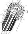
- the self-synchronous synchronous motor comprises a casing (1) surrounding first, in the direction of the central transmission shaft (2), a stator having a peripheral magnetic yoke (4) and stator coils (5) having a wound winding on a carcass (6).
- These coils (5) are housed in axial recesses formed in a stack of sheets forming a laminated polar crown (3) covered by the cylindrical yoke (4).
- the rotor comprises a laminated hub (7) consisting of stacked sheets, and has around its periphery permanent magnets (8) in the form of rounded tiles conforming to its cylindrical outer surface.
- the housing (1) comprises, in a portion which extends beyond the stator and the rotor, an extension (10) provided with external splines (11) which houses the device of immobilization and braking of the invention. This is placed beyond a partition (9) connecting the housing to a bearing / ball bearing (not shown, see below). figure 3 ), the outer ring is clamped in the central annular portion of this partition (9).
- the device of the invention more precisely comprises, in this variant, a disc (12) secured to the shaft (2) via a ring (13), and whose peripheral ring (27) comprises housings (14) in which permanent magnets (15) are placed here in the form of magnetic circular pellets.
- the inner wall (28) of the extension (10) of the housing (1) also comprises housings (16) arranged facing the peripheral ring of the disc (12) in which are housed the same magnetic pellets (15), the axial positioning of the disk (12) on the shaft (2) and peripheral of the housings (15, 16) being provided such that said pellets may be coaxial, in radial directions, in a number n of angular positions corresponding to the number of permanent magnets .
- the identical shape of the magnets (15) on the fixed side and on the moving side optimizes the ducting of the magnetic fluxes, in particular the radial ones, and makes braking more efficient.
- magnets are 6, which is only a possibility, non-binding. Their number may also depend on the material used: it is recommended to put more when it comes to ferrite, while it is less necessary with rare earth magnets that offer better yields.
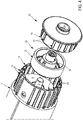
- the rotating or rotating elements (22) and piece (20) respectively have a peripheral wall (21) and (19) of cylindrical shape which is made of a magnetized plastoferrite material in the mass (see in particular FIG. figure 4 ), in successive magnetized sectors (25) of opposite polarization direction, as will be shown in more detail particularly with reference to the figures 5 .
- the rotating part (22), which provides the mechanical connection with a gear, comprises for this purpose a connecting sleeve (18) extending its central hub secured, via the ring (13), to the transmission shaft (2). rotor.
- the braking device is placed beyond the partition (9) whose central sleeve surrounds a bearing / ball bearing (17), partition (9) separating it from the rotor / stator assembly of the motor.
- the fixed element (20) actually a closure cap, fits inside the extension (10) of the housing (1).
- the outer face of its peripheral wall (19) fits tight inside the inner wall of this extension (10).
- Axial grooves (23) disposed on said outer face of the wall (19) are provided to cooperate with axial grooves (24) of corresponding shape formed in the inner face of said extension (10).
- These sets of grooves (23) / grooves (24) allow precise angular positioning of the cover (20), and act as keying elements placed on the part (20).
- the resulting relative positioning allows the superposition of the braking implemented by means of the invention and the specific relaxation torque of the motor.
- the brake stator is indexed, thanks to these grooves (23) / grooves (24) so that the braking is added.
- the connecting sleeve (18) of the part (21) remains accessible through the cover (20) through a through hole (26) of the cover (20) coaxial with the transmission shaft (2).
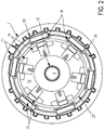
- each of the fixed (20) and movable (22) elements of the device of the invention comprises, on its respectively internal and external peripheral wall, 18 magnetized angular sectors (25) of polarity direction successively. reversed. For each of them, the north (N) and south (S) poles are indicated in the figures, and succeed one another alternately.
- the angular sectors being the same angle on the two parts opposite, the magnetic surfaces (25) facing are, if not equal, at least close. In case of radial alignment, they are included in the same angular sector, and the channelization of the field lines is therefore optimal in this direction, but also in a tangential direction due to the adjacency of the magnetized zones.
- the connecting sleeve (18) with the reducer extends and is in one piece with the ring (13 '), directly inserted on the shaft (2). It is therefore directly connected to the reducer without connection to the part (22), much more fragile because of its constituent material (ferrite).
Landscapes
- Engineering & Computer Science (AREA)
- Power Engineering (AREA)
- Connection Of Motors, Electrical Generators, Mechanical Devices, And The Like (AREA)
- Permanent Magnet Type Synchronous Machine (AREA)
Claims (13)
- Vorrichtung zum Bremsen und Immobilisierung eines Rotors einer selbstgesteuerten synchronen Rotationsmaschine in der Art eines bürstenlosen Gleichstrommotors, umfassend mindestens ein erstes Element (12,22), das relativ zu Rotor ortsfest montiert ist, und mindestens ein zweites Element (10, 20), das relativ zum Stator ortsfest montiert ist, Mittel (15, 25) zur Erzeugung von Magnetfeldern, die an das erste Element (12, 22) angeschlossen sind und mit Mitteln (15, 25) zur Erzeugung von Magnetfeldern zusammenwirken, die an das zweite Element (10, 20) angeschlossen sind, wobei die Mittel (15, 25) Linien radialer Felder erzeugen und jeweils im ersten (12, 22) und zweiten Element (10, 20) derart lokalisiert und positioniert sind, dass radiale Linien derselben Ausrichtung in mindestens (n > 1) einer vorgegebenen diskreten Winkelposition kolinear sind,
dadurch gekennzeichnet, dass das erste Element (22) eine Verbindung mit der Antriebswelle des Rotors über eine Buchse (13, 13') sowie eine Verbindung mit einem Getriebemotor in Form einer mit dem Element (22) oder der Buchse (13') integrierten Verbindungsmuffe (18) umfasst. - Vorrichtung zum Bremsen und Immobilisierung eines Rotors nach dem vorstehenden Anspruch, dadurch gekennzeichnet, dass sie vom Rotor und Stator getrennt ist durch eine Trennwand (9) eines Gehäuses (1) des Motors, die den Motor mit einem auf der Antriebswelle (2) des Rotors befestigten Lager/Kugellagerring verbindet.
- Vorrichtung zum Bremsen und Immobilisierung eines Rotors nach dem vorstehenden Anspruch, dadurch gekennzeichnet, dass :- eine erste Wand (27, 21) des ersten Elements (12, 22), die in Richtung des Stators ausgerichtet ist, mit mindestens einem Dauermagnetisierungsbereich (15, 25) ausgestattet ist, dessen Polarität radial zur Rotationsachse des Rotors ausgerichtet ist;- eine zweite Wand (28, 19) des zweiten Elements (10, 20), die in Richtung des Rotors ausgerichtet ist, mit mindestens einem Dauermagnetisierungsbereich (15, 25) ausgestattet ist, dessen Polarität radial zur Rotationsachse des Rotors ausgerichtet ist;- wobei die erste (27, 21) und zweite (28, 19) Wand einander zugewandt sind und mindestens eine der Wänder n (n > 1) Dauermagnetisierungsbereiche (15, 25) aufweist;- wenn n > 1, ist n eine gerade Zahl und die benachbarten Dauermagnetisierungsbereiche (15, 25) weisen entgegengesetzte Polaritäten auf.
- Vorrichtung zum Bremsen und Immobilisierung eines Rotors nach dem vorstehenden Anspruch, dadurch gekennzeichnet, dass die Dauermagnetisierungsbereiche mit Dauermagneten (15) ausgebildet sind, die einander zugewandt in den Wänden (27, 28) angeordnet sind.
- Vorrichtung zum Bremsen und Immobilisierung eines Rotors nach einem der Ansprüche 3 und 4, dadurch gekennzeichnet, dass, wenn n>l, die Dauermagnetisierungsbereiche (25) bzw. die Dauermagneten (15) regelmäßig in den Wänden (19, 21; 27, 28) verteilt sind, in denen sie vorgesehen sind.
- Vorrichtung zum Bremsen und Immobilisierung eines Rotors nach dem vorstehenden Anspruch, dadurch gekennzeichnet, dass die Anzahl der Dauermagnetisierungsbereiche (25) bzw. Dauermagneten (15) in jeder Wand (19, 21; 27, 28) gleich ist.
- Vorrichtung zum Bremsen und Immobilisierung eines Rotors nach einem der Ansprüche 3 - 6, dadurch gekennzeichnet, dass die Dauermagnetisierungsbereiche (15, 25) im Wesentlichen gleiche, einander zugewandte polare Oberflächen aufweisen.
- Vorrichtung zum Bremsen und Immobilisierung eines Rotors nach einem der Ansprüche 3-7, dadurch gekennzeichnet, dass die erste Wand (27) eine äußere Umfangswand einer Scheibe (12) ist, die auf einer mit dem Rotor integrierten Antriebswelle (2) fixiert ist.
- Vorrichtung zum Bremsen und Immobilisierung eines Rotors nach einem der Ansprüche 3-8, dadurch gekennzeichnet, dass die zweite Wand (28) eine innere Umfangswand eines ringförmigen Abschnitts (10) eines Gehäuses (1) ist, das den Stator umgibt.
- Vorrichtung zum Bremsen und Immobilisierung eines Rotors nach einem der Ansprüche 3-8, dadurch gekennzeichnet, dass die zweite Wand (19) eine innere Umfangswand einer Haube (20) zum Abschließen des Gehäuses (1) am Ausgang der Antriebswelle (2) des Rotors ist.
- Vorrichtung zum Bremsen und Immobilisierung eines Rotors nach einem der Ansprüche 8 - 10, dadurch gekennzeichnet, dass die Wände (27, 28) Gehäuse aufweisen, in denen Dauermagneten angeordnet sind.
- Vorrichtung zum Bremsen und Immobilisierung eines Rotors nach einem der Ansprüche 8 - 10, dadurch gekennzeichnet, dass die Wände (19, 21) aus Plastoferrit bestehen und gewinkelte Dauermagnetisierungssektoren (25) aufweisen.
- Vorrichtung zum Bremsen und Immobilisierung eines Rotors nach einem der vorstehenden Ansprüche, dadurch gekennzeichnet, dass das erste (12, 22) und zweite (10, 20) Element am Ausgang der Antriebswelle (2) des Rotors in einer Verlängerung der Zylinderköpfe und der Magnetpole des Rotors (7) und des Stators (3, 4) angeordnet sind.
Priority Applications (1)
| Application Number | Priority Date | Filing Date | Title |
|---|---|---|---|
| PL16180986T PL3121942T3 (pl) | 2015-07-23 | 2016-07-25 | Urządzenie do hamowania i unieruchamiania wirnika synchronicznej maszyny obrotowej |
Applications Claiming Priority (1)
| Application Number | Priority Date | Filing Date | Title |
|---|---|---|---|
| FR1555829A FR3039340B1 (fr) | 2015-07-23 | 2015-07-23 | Dispositif de freinage et d'immobilisation d'un rotor d'une machine tournante synchrone. |
Publications (2)
| Publication Number | Publication Date |
|---|---|
| EP3121942A1 EP3121942A1 (de) | 2017-01-25 |
| EP3121942B1 true EP3121942B1 (de) | 2018-09-12 |
Family
ID=54366308
Family Applications (1)
| Application Number | Title | Priority Date | Filing Date |
|---|---|---|---|
| EP16180986.8A Active EP3121942B1 (de) | 2015-07-23 | 2016-07-25 | Brems- und sperrvorrichtung für den läufer einer synchronmaschine |
Country Status (4)
| Country | Link |
|---|---|
| EP (1) | EP3121942B1 (de) |
| ES (1) | ES2690267T3 (de) |
| FR (1) | FR3039340B1 (de) |
| PL (1) | PL3121942T3 (de) |
Families Citing this family (3)
| Publication number | Priority date | Publication date | Assignee | Title |
|---|---|---|---|---|
| FR3142624A1 (fr) * | 2022-11-30 | 2024-05-31 | Bhg | Intégration électronique dans un moteur sans balais |
| KR20250045214A (ko) * | 2023-09-25 | 2025-04-01 | 엘지이노텍 주식회사 | 모터 |
| DE102024123190A1 (de) * | 2024-08-14 | 2026-02-19 | Selve Vermögensverwaltung GmbH & Co. KG | Vorrichtung zum Antrieb einer Wickelwelle |
Citations (3)
| Publication number | Priority date | Publication date | Assignee | Title |
|---|---|---|---|---|
| JP3183409B2 (ja) * | 1991-04-04 | 2001-07-09 | 株式会社安川電機 | ホールディングトルクブレーキ付きモータの制御方法と装置 |
| JP2004257547A (ja) * | 2003-02-25 | 2004-09-16 | Kawaden:Kk | 回転体のブレーキ装置 |
| EP2393187A2 (de) * | 2010-06-02 | 2011-12-07 | The Boeing Company | Elektromagnetische, kontaktlose Bremse |
Family Cites Families (5)
| Publication number | Priority date | Publication date | Assignee | Title |
|---|---|---|---|---|
| US5467266A (en) * | 1991-09-03 | 1995-11-14 | Lutron Electronics Co., Inc. | Motor-operated window cover |
| US5465815A (en) * | 1994-01-10 | 1995-11-14 | Ikegami; Iwao | Magnetic brake |
| JP3897914B2 (ja) * | 1998-09-04 | 2007-03-28 | 山洋電気株式会社 | 電動アクチュエータ |
| US6967418B2 (en) * | 2003-05-23 | 2005-11-22 | Somfy Sas | Magnetic brake for powered window covering |
| WO2014147612A1 (en) * | 2013-03-19 | 2014-09-25 | Vastech Holdings Ltd. | A device and method for using a magnetic clutch in bldc motors |
-
2015
- 2015-07-23 FR FR1555829A patent/FR3039340B1/fr not_active Expired - Fee Related
-
2016
- 2016-07-25 PL PL16180986T patent/PL3121942T3/pl unknown
- 2016-07-25 ES ES16180986.8T patent/ES2690267T3/es active Active
- 2016-07-25 EP EP16180986.8A patent/EP3121942B1/de active Active
Patent Citations (3)
| Publication number | Priority date | Publication date | Assignee | Title |
|---|---|---|---|---|
| JP3183409B2 (ja) * | 1991-04-04 | 2001-07-09 | 株式会社安川電機 | ホールディングトルクブレーキ付きモータの制御方法と装置 |
| JP2004257547A (ja) * | 2003-02-25 | 2004-09-16 | Kawaden:Kk | 回転体のブレーキ装置 |
| EP2393187A2 (de) * | 2010-06-02 | 2011-12-07 | The Boeing Company | Elektromagnetische, kontaktlose Bremse |
Also Published As
| Publication number | Publication date |
|---|---|
| EP3121942A1 (de) | 2017-01-25 |
| FR3039340A1 (fr) | 2017-01-27 |
| ES2690267T3 (es) | 2018-11-20 |
| FR3039340B1 (fr) | 2019-07-12 |
| PL3121942T3 (pl) | 2019-04-30 |
Similar Documents
| Publication | Publication Date | Title |
|---|---|---|
| EP2153076B1 (de) | Mit einer indexierung ausgestattete tragevorrichtung | |
| EP0151159A1 (de) | Mehrphasiger motor mit einem magnetizierten, pro fläche n/2 polpaare aufweisenden läufer | |
| EP1251629A1 (de) | Elektrische Maschine mit mindestens einem Magnetfelddetektor | |
| FR2678448A1 (fr) | Moteur a reluctance variable ayant des bobinages enroules en un fil en feuille mince. | |
| EP3121942B1 (de) | Brems- und sperrvorrichtung für den läufer einer synchronmaschine | |
| EP0157694B1 (de) | Elektromagnetische radiale Lagerung mit massivem Rotor zur Dämpfung kritischer Frequenzen | |
| FR2594272A2 (fr) | Machine synchrone tournant a grande vitesse a rotor a aimants permanents d'induction magnetique orthoradiale | |
| EP3286823B1 (de) | Elektrische maschine und verfahren zum dynamischen auswuchten des rotors dieser elektrischen maschine | |
| EP3934060A1 (de) | Elektromaschine mit konzentrierter wicklung | |
| FR3049781A1 (fr) | Actionneur electromecanique pour la commande d'ecrans et installation domotique comprenant un tel actionneur | |
| WO2016001495A2 (fr) | Moteur électromagnétique polyentrefers et à flux magnétique radial à rotor encadré par deux stators avec diminution du couple de détente | |
| EP3125412B1 (de) | Selbstgesteuerte synchron umlaufende maschine mit bremsvorrichtung | |
| EP2880744A1 (de) | Aktuator mit zwei magnetlagermotoren | |
| EP3229348B1 (de) | Rotor für eine elektrische maschine | |
| EP2878759B1 (de) | Elektromechanisches Stellglied, und Verschluss- oder Sonnenschutzanlage, die ein solches Stellglied umfasst | |
| FR2717947A1 (fr) | Actionneur électromagnétique rotatif à débattement angulaire limité. | |
| EP3139473B1 (de) | Elektrisch umlaufende maschine, die mit verbesserten nachverfolgungsmitteln der winkelposition des rotors ausgestattet ist | |
| WO2014161911A1 (fr) | Moteur electrique a faible couple de court-circuit, dispositif de motorisation a plusieurs moteurs et procede de fabrication d'un tel moteur | |
| FR3038158A1 (fr) | Machine electrique tournante synchrone compacte. | |
| WO2018087436A1 (fr) | Actionneur électromagnétique à flux axial et série auxiliaire de bobinages | |
| EP3349338A1 (de) | Elektrischer rohrmotor mit dauermagneten | |
| EP3017525B1 (de) | Anordnung eines elektrischen stellantriebs und verfahren zum herstellen eines motors eines zu einer solchen anordnung gehöhrenden stellantriebs. | |
| FR3034587B1 (fr) | Procede de fabrication d'un rotor d'un moteur synchrone sans balais a concentration de flux. | |
| FR2963710A1 (fr) | Moteur electrique. | |
| WO2008026032A1 (fr) | Machine electrique a stator muni de griffes et de bobinages deportes |
Legal Events
| Date | Code | Title | Description |
|---|---|---|---|
| PUAI | Public reference made under article 153(3) epc to a published international application that has entered the european phase |
Free format text: ORIGINAL CODE: 0009012 |
|
| STAA | Information on the status of an ep patent application or granted ep patent |
Free format text: STATUS: THE APPLICATION HAS BEEN PUBLISHED |
|
| AK | Designated contracting states |
Kind code of ref document: A1 Designated state(s): AL AT BE BG CH CY CZ DE DK EE ES FI FR GB GR HR HU IE IS IT LI LT LU LV MC MK MT NL NO PL PT RO RS SE SI SK SM TR |
|
| AX | Request for extension of the european patent |
Extension state: BA ME |
|
| STAA | Information on the status of an ep patent application or granted ep patent |
Free format text: STATUS: REQUEST FOR EXAMINATION WAS MADE |
|
| 17P | Request for examination filed |
Effective date: 20170720 |
|
| RBV | Designated contracting states (corrected) |
Designated state(s): AL AT BE BG CH CY CZ DE DK EE ES FI FR GB GR HR HU IE IS IT LI LT LU LV MC MK MT NL NO PL PT RO RS SE SI SK SM TR |
|
| STAA | Information on the status of an ep patent application or granted ep patent |
Free format text: STATUS: EXAMINATION IS IN PROGRESS |
|
| 17Q | First examination report despatched |
Effective date: 20170908 |
|
| RIC1 | Information provided on ipc code assigned before grant |
Ipc: H02K 7/11 20060101AFI20180328BHEP Ipc: H02K 49/10 20060101ALN20180328BHEP |
|
| GRAP | Despatch of communication of intention to grant a patent |
Free format text: ORIGINAL CODE: EPIDOSNIGR1 |
|
| STAA | Information on the status of an ep patent application or granted ep patent |
Free format text: STATUS: GRANT OF PATENT IS INTENDED |
|
| INTG | Intention to grant announced |
Effective date: 20180507 |
|
| GRAS | Grant fee paid |
Free format text: ORIGINAL CODE: EPIDOSNIGR3 |
|
| GRAA | (expected) grant |
Free format text: ORIGINAL CODE: 0009210 |
|
| STAA | Information on the status of an ep patent application or granted ep patent |
Free format text: STATUS: THE PATENT HAS BEEN GRANTED |
|
| AK | Designated contracting states |
Kind code of ref document: B1 Designated state(s): AL AT BE BG CH CY CZ DE DK EE ES FI FR GB GR HR HU IE IS IT LI LT LU LV MC MK MT NL NO PL PT RO RS SE SI SK SM TR |
|
| REG | Reference to a national code |
Ref country code: GB Ref legal event code: FG4D Free format text: NOT ENGLISH |
|
| REG | Reference to a national code |
Ref country code: CH Ref legal event code: EP |
|
| REG | Reference to a national code |
Ref country code: IE Ref legal event code: FG4D Free format text: LANGUAGE OF EP DOCUMENT: FRENCH |
|
| REG | Reference to a national code |
Ref country code: DE Ref legal event code: R096 Ref document number: 602016005503 Country of ref document: DE |
|
| REG | Reference to a national code |
Ref country code: AT Ref legal event code: REF Ref document number: 1041744 Country of ref document: AT Kind code of ref document: T Effective date: 20181015 |
|
| REG | Reference to a national code |
Ref country code: ES Ref legal event code: FG2A Ref document number: 2690267 Country of ref document: ES Kind code of ref document: T3 Effective date: 20181120 |
|
| REG | Reference to a national code |
Ref country code: NL Ref legal event code: MP Effective date: 20180912 |
|
| REG | Reference to a national code |
Ref country code: LT Ref legal event code: MG4D |
|
| PG25 | Lapsed in a contracting state [announced via postgrant information from national office to epo] |
Ref country code: FI Free format text: LAPSE BECAUSE OF FAILURE TO SUBMIT A TRANSLATION OF THE DESCRIPTION OR TO PAY THE FEE WITHIN THE PRESCRIBED TIME-LIMIT Effective date: 20180912 Ref country code: LT Free format text: LAPSE BECAUSE OF FAILURE TO SUBMIT A TRANSLATION OF THE DESCRIPTION OR TO PAY THE FEE WITHIN THE PRESCRIBED TIME-LIMIT Effective date: 20180912 Ref country code: NO Free format text: LAPSE BECAUSE OF FAILURE TO SUBMIT A TRANSLATION OF THE DESCRIPTION OR TO PAY THE FEE WITHIN THE PRESCRIBED TIME-LIMIT Effective date: 20181212 Ref country code: BG Free format text: LAPSE BECAUSE OF FAILURE TO SUBMIT A TRANSLATION OF THE DESCRIPTION OR TO PAY THE FEE WITHIN THE PRESCRIBED TIME-LIMIT Effective date: 20181212 Ref country code: SE Free format text: LAPSE BECAUSE OF FAILURE TO SUBMIT A TRANSLATION OF THE DESCRIPTION OR TO PAY THE FEE WITHIN THE PRESCRIBED TIME-LIMIT Effective date: 20180912 Ref country code: GR Free format text: LAPSE BECAUSE OF FAILURE TO SUBMIT A TRANSLATION OF THE DESCRIPTION OR TO PAY THE FEE WITHIN THE PRESCRIBED TIME-LIMIT Effective date: 20181213 Ref country code: RS Free format text: LAPSE BECAUSE OF FAILURE TO SUBMIT A TRANSLATION OF THE DESCRIPTION OR TO PAY THE FEE WITHIN THE PRESCRIBED TIME-LIMIT Effective date: 20180912 |
|
| PG25 | Lapsed in a contracting state [announced via postgrant information from national office to epo] |
Ref country code: HR Free format text: LAPSE BECAUSE OF FAILURE TO SUBMIT A TRANSLATION OF THE DESCRIPTION OR TO PAY THE FEE WITHIN THE PRESCRIBED TIME-LIMIT Effective date: 20180912 Ref country code: LV Free format text: LAPSE BECAUSE OF FAILURE TO SUBMIT A TRANSLATION OF THE DESCRIPTION OR TO PAY THE FEE WITHIN THE PRESCRIBED TIME-LIMIT Effective date: 20180912 Ref country code: AL Free format text: LAPSE BECAUSE OF FAILURE TO SUBMIT A TRANSLATION OF THE DESCRIPTION OR TO PAY THE FEE WITHIN THE PRESCRIBED TIME-LIMIT Effective date: 20180912 |
|
| REG | Reference to a national code |
Ref country code: AT Ref legal event code: MK05 Ref document number: 1041744 Country of ref document: AT Kind code of ref document: T Effective date: 20180912 |
|
| PG25 | Lapsed in a contracting state [announced via postgrant information from national office to epo] |
Ref country code: AT Free format text: LAPSE BECAUSE OF FAILURE TO SUBMIT A TRANSLATION OF THE DESCRIPTION OR TO PAY THE FEE WITHIN THE PRESCRIBED TIME-LIMIT Effective date: 20180912 Ref country code: EE Free format text: LAPSE BECAUSE OF FAILURE TO SUBMIT A TRANSLATION OF THE DESCRIPTION OR TO PAY THE FEE WITHIN THE PRESCRIBED TIME-LIMIT Effective date: 20180912 Ref country code: RO Free format text: LAPSE BECAUSE OF FAILURE TO SUBMIT A TRANSLATION OF THE DESCRIPTION OR TO PAY THE FEE WITHIN THE PRESCRIBED TIME-LIMIT Effective date: 20180912 Ref country code: NL Free format text: LAPSE BECAUSE OF FAILURE TO SUBMIT A TRANSLATION OF THE DESCRIPTION OR TO PAY THE FEE WITHIN THE PRESCRIBED TIME-LIMIT Effective date: 20180912 Ref country code: CZ Free format text: LAPSE BECAUSE OF FAILURE TO SUBMIT A TRANSLATION OF THE DESCRIPTION OR TO PAY THE FEE WITHIN THE PRESCRIBED TIME-LIMIT Effective date: 20180912 Ref country code: IS Free format text: LAPSE BECAUSE OF FAILURE TO SUBMIT A TRANSLATION OF THE DESCRIPTION OR TO PAY THE FEE WITHIN THE PRESCRIBED TIME-LIMIT Effective date: 20190112 |
|
| PG25 | Lapsed in a contracting state [announced via postgrant information from national office to epo] |
Ref country code: PT Free format text: LAPSE BECAUSE OF FAILURE TO SUBMIT A TRANSLATION OF THE DESCRIPTION OR TO PAY THE FEE WITHIN THE PRESCRIBED TIME-LIMIT Effective date: 20190112 Ref country code: SK Free format text: LAPSE BECAUSE OF FAILURE TO SUBMIT A TRANSLATION OF THE DESCRIPTION OR TO PAY THE FEE WITHIN THE PRESCRIBED TIME-LIMIT Effective date: 20180912 Ref country code: SM Free format text: LAPSE BECAUSE OF FAILURE TO SUBMIT A TRANSLATION OF THE DESCRIPTION OR TO PAY THE FEE WITHIN THE PRESCRIBED TIME-LIMIT Effective date: 20180912 |
|
| REG | Reference to a national code |
Ref country code: DE Ref legal event code: R097 Ref document number: 602016005503 Country of ref document: DE |
|
| PLBE | No opposition filed within time limit |
Free format text: ORIGINAL CODE: 0009261 |
|
| STAA | Information on the status of an ep patent application or granted ep patent |
Free format text: STATUS: NO OPPOSITION FILED WITHIN TIME LIMIT |
|
| PG25 | Lapsed in a contracting state [announced via postgrant information from national office to epo] |
Ref country code: DK Free format text: LAPSE BECAUSE OF FAILURE TO SUBMIT A TRANSLATION OF THE DESCRIPTION OR TO PAY THE FEE WITHIN THE PRESCRIBED TIME-LIMIT Effective date: 20180912 |
|
| 26N | No opposition filed |
Effective date: 20190613 |
|
| PG25 | Lapsed in a contracting state [announced via postgrant information from national office to epo] |
Ref country code: SI Free format text: LAPSE BECAUSE OF FAILURE TO SUBMIT A TRANSLATION OF THE DESCRIPTION OR TO PAY THE FEE WITHIN THE PRESCRIBED TIME-LIMIT Effective date: 20180912 |
|
| PG25 | Lapsed in a contracting state [announced via postgrant information from national office to epo] |
Ref country code: MC Free format text: LAPSE BECAUSE OF FAILURE TO SUBMIT A TRANSLATION OF THE DESCRIPTION OR TO PAY THE FEE WITHIN THE PRESCRIBED TIME-LIMIT Effective date: 20180912 |
|
| REG | Reference to a national code |
Ref country code: CH Ref legal event code: PL |
|
| PG25 | Lapsed in a contracting state [announced via postgrant information from national office to epo] |
Ref country code: TR Free format text: LAPSE BECAUSE OF FAILURE TO SUBMIT A TRANSLATION OF THE DESCRIPTION OR TO PAY THE FEE WITHIN THE PRESCRIBED TIME-LIMIT Effective date: 20180912 |
|
| REG | Reference to a national code |
Ref country code: BE Ref legal event code: MM Effective date: 20190731 |
|
| PG25 | Lapsed in a contracting state [announced via postgrant information from national office to epo] |
Ref country code: CH Free format text: LAPSE BECAUSE OF NON-PAYMENT OF DUE FEES Effective date: 20190731 Ref country code: LI Free format text: LAPSE BECAUSE OF NON-PAYMENT OF DUE FEES Effective date: 20190731 Ref country code: LU Free format text: LAPSE BECAUSE OF NON-PAYMENT OF DUE FEES Effective date: 20190725 Ref country code: BE Free format text: LAPSE BECAUSE OF NON-PAYMENT OF DUE FEES Effective date: 20190731 |
|
| PG25 | Lapsed in a contracting state [announced via postgrant information from national office to epo] |
Ref country code: IE Free format text: LAPSE BECAUSE OF NON-PAYMENT OF DUE FEES Effective date: 20190725 |
|
| GBPC | Gb: european patent ceased through non-payment of renewal fee |
Effective date: 20200725 |
|
| PG25 | Lapsed in a contracting state [announced via postgrant information from national office to epo] |
Ref country code: GB Free format text: LAPSE BECAUSE OF NON-PAYMENT OF DUE FEES Effective date: 20200725 |
|
| PG25 | Lapsed in a contracting state [announced via postgrant information from national office to epo] |
Ref country code: CY Free format text: LAPSE BECAUSE OF FAILURE TO SUBMIT A TRANSLATION OF THE DESCRIPTION OR TO PAY THE FEE WITHIN THE PRESCRIBED TIME-LIMIT Effective date: 20180912 |
|
| PG25 | Lapsed in a contracting state [announced via postgrant information from national office to epo] |
Ref country code: HU Free format text: LAPSE BECAUSE OF FAILURE TO SUBMIT A TRANSLATION OF THE DESCRIPTION OR TO PAY THE FEE WITHIN THE PRESCRIBED TIME-LIMIT; INVALID AB INITIO Effective date: 20160725 Ref country code: MT Free format text: LAPSE BECAUSE OF FAILURE TO SUBMIT A TRANSLATION OF THE DESCRIPTION OR TO PAY THE FEE WITHIN THE PRESCRIBED TIME-LIMIT Effective date: 20180912 |
|
| PG25 | Lapsed in a contracting state [announced via postgrant information from national office to epo] |
Ref country code: MK Free format text: LAPSE BECAUSE OF FAILURE TO SUBMIT A TRANSLATION OF THE DESCRIPTION OR TO PAY THE FEE WITHIN THE PRESCRIBED TIME-LIMIT Effective date: 20180912 |
|
| PGFP | Annual fee paid to national office [announced via postgrant information from national office to epo] |
Ref country code: PL Payment date: 20250624 Year of fee payment: 10 |
|
| PGFP | Annual fee paid to national office [announced via postgrant information from national office to epo] |
Ref country code: FR Payment date: 20250623 Year of fee payment: 10 |
|
| PGFP | Annual fee paid to national office [announced via postgrant information from national office to epo] |
Ref country code: ES Payment date: 20250811 Year of fee payment: 10 |
|
| PGFP | Annual fee paid to national office [announced via postgrant information from national office to epo] |
Ref country code: DE Payment date: 20250711 Year of fee payment: 10 |
|
| PGFP | Annual fee paid to national office [announced via postgrant information from national office to epo] |
Ref country code: IT Payment date: 20250714 Year of fee payment: 10 |