EP3121996B1 - Synchronisationsstörungsverarbeitungsverfahren und system für ein takt- und zeitsynchronisierungsnetzwerk - Google Patents
Synchronisationsstörungsverarbeitungsverfahren und system für ein takt- und zeitsynchronisierungsnetzwerk Download PDFInfo
- Publication number
- EP3121996B1 EP3121996B1 EP14890086.3A EP14890086A EP3121996B1 EP 3121996 B1 EP3121996 B1 EP 3121996B1 EP 14890086 A EP14890086 A EP 14890086A EP 3121996 B1 EP3121996 B1 EP 3121996B1
- Authority
- EP
- European Patent Office
- Prior art keywords
- clock
- network element
- time
- time source
- standby
- Prior art date
- Legal status (The legal status is an assumption and is not a legal conclusion. Google has not performed a legal analysis and makes no representation as to the accuracy of the status listed.)
- Active
Links
Images


Classifications
-
- H—ELECTRICITY
- H04—ELECTRIC COMMUNICATION TECHNIQUE
- H04L—TRANSMISSION OF DIGITAL INFORMATION, e.g. TELEGRAPHIC COMMUNICATION
- H04L41/00—Arrangements for maintenance, administration or management of data switching networks, e.g. of packet switching networks
- H04L41/12—Discovery or management of network topologies
-
- H—ELECTRICITY
- H04—ELECTRIC COMMUNICATION TECHNIQUE
- H04L—TRANSMISSION OF DIGITAL INFORMATION, e.g. TELEGRAPHIC COMMUNICATION
- H04L41/00—Arrangements for maintenance, administration or management of data switching networks, e.g. of packet switching networks
-
- H—ELECTRICITY
- H04—ELECTRIC COMMUNICATION TECHNIQUE
- H04L—TRANSMISSION OF DIGITAL INFORMATION, e.g. TELEGRAPHIC COMMUNICATION
- H04L41/00—Arrangements for maintenance, administration or management of data switching networks, e.g. of packet switching networks
- H04L41/06—Management of faults, events, alarms or notifications
- H04L41/0654—Management of faults, events, alarms or notifications using network fault recovery
- H04L41/0663—Performing the actions predefined by failover planning, e.g. switching to standby network elements
-
- H—ELECTRICITY
- H04—ELECTRIC COMMUNICATION TECHNIQUE
- H04L—TRANSMISSION OF DIGITAL INFORMATION, e.g. TELEGRAPHIC COMMUNICATION
- H04L41/00—Arrangements for maintenance, administration or management of data switching networks, e.g. of packet switching networks
- H04L41/06—Management of faults, events, alarms or notifications
- H04L41/0654—Management of faults, events, alarms or notifications using network fault recovery
- H04L41/0668—Management of faults, events, alarms or notifications using network fault recovery by dynamic selection of recovery network elements, e.g. replacement by the most appropriate element after failure
-
- H—ELECTRICITY
- H04—ELECTRIC COMMUNICATION TECHNIQUE
- H04L—TRANSMISSION OF DIGITAL INFORMATION, e.g. TELEGRAPHIC COMMUNICATION
- H04L41/00—Arrangements for maintenance, administration or management of data switching networks, e.g. of packet switching networks
- H04L41/06—Management of faults, events, alarms or notifications
- H04L41/0686—Additional information in the notification, e.g. enhancement of specific meta-data
Definitions
- the present invention relates to a clock and time synchronization network, and thereby relates to a method and system for processing a synchronization failure for a clock and time synchronization network.
- Clock synchronization networks represented by synchronization Ethernets, implement synchronization of working frequencies and pulse phases of multiple network devices by transmitting pulse signals through link and physical layers; and time synchronization networks, represented by the network measurement and control system's Precision Time Protocol (PTP), implement synchronization of temporal phases of multiple network devices.
- PTP Precision Time Protocol
- a clock synchronization network element delivers a clock state and a clock quality level to the downstream through a notification message step by step.
- the downstream network element analyzes notification messages received by it from different links, and decides a link of which a lock is synchronized in combination with a state of itself. After the synchronization, the downstream network element continues to deliver a clock synchronization state and a clock quality level of the present network element to a downstream network element through a notification message.
- a clock recovery process of the current network element is as follows: After the network element finds that clock synchronization fails, the network element firstly enters a holding state and transmits a failure notification and a clock quality level when it is in the holding state to a next stage of network element. After receiving the information, the next stage of network element compares its own clock quality level with the clock quality level of the previous stage of network element.
- the next stage of network element enters a holding state and continues to transmit the failure notification and its own clock quality level to a next stage of network element. If after the comparison, it shows that the clock quality level of the previous stage of network element is smaller than its own clock quality level, the network element directly enters a holding state and continues to transmit the failure notification and its own clock quality level to a next stage of network element, until a certain stage of network element finds a standby clock source and is locked with the standby clock source.
- the network element is directly locked with a clock of the previous stage of network element, at this point, the previous stage of network element is equivalent to a standby clock source. Then, in a reverse link, the network element which is locked with the standby clock notifies the previous stage of network element to lock with it, until the network element on the reverse link which firstly enters a holding state also enters a clock locked state.
- a fiber break failure occurs between network element 1 and network element 2, and then the network element 2 enters a clock holding state and transmits a failure notification and a clock quality level to network element 3.
- the network element 3 does not have other standby clock sources, and after receiving the notification transmitted by the network element 2, the network element 3 compares its own clock quality level with the clock quality level of the network element 2, and both of the clock quality levels are the same, then the network element 3 continues to be locked with the network element 2 and transmits the failure notification and the clock quality level to network element 4.
- the network element 4 does not have other standby clock sources, and after receiving the notification transmitted by the network element 3, the network element 4 continues to compare its own clock quality level with the clock quality level of the network element 3, and both of the clock quality levels are the same, then the network element 4 continues to be locked with the network element 3 and transmits the failure notification and the clock quality level to network element 5.
- the network element 5 has a standby network clock source, which is a clock of network element 6. Therefore, after receiving the notification of the network element 4, the network element 5 is immediately locked with the clock of the network element 6, and then notifies the network element 4 to lock with its own clock. After the network element 4 is locked with the clock of the network element 5, the network element 4 notifies the network element 3 to lock with its own clock.
- Network elements which are traversed in the whole failure recovery flow are network element 2 ⁇ ⁇ network element 3 ⁇ ⁇ network element 4 ⁇ ⁇ network element 5 ⁇ ⁇ network element 4 ⁇ ⁇ network element 3 ⁇ ⁇ network element 2.
- each network element detects and makes a response to its own synchronization clock offset change condition, and the network element transmits a message to a next stage of network element after a relatively large time interval, in this case, before the downstream network element enters a holding state according to the received message, an error generated by the upstream network element due to a clock synchronization failure has already been delivered to the next stage of network element, and the clock of the next stage of network element has deviated from a normal reference.
- Fig. 1 when the network element 2 detects that its clock is abnormal, a clock error has already taken effect on the network element 2, and the clock of the network element 2 is modified. This clock error may continue to be delivered to the network element 3.
- the clock of the network element 3 has been deviated and begins to be delivered to the network element 4.
- the time required for the downstream network element to enter a clock holding state is delayed, and an error of the clock held by the downstream network element increases.
- the clock locking method is unable to compensate for the error.
- the document GB 2341749 A discloses a method of detecting or anticipating synchronisation faults provided for a digital telecommunications network (1) having a plurality of nodes, each of which obtains a synchronisation signal from a source comprising a selected one of the other nodes, the network is interrogated to obtain data on its topology and, for each node, the identity of the selected respective other node, this information is used to construct a virtual model (12) of the network, and the model is then inspected if any node of the system is to select an alternative synchronisation source, since the data on the topology of the network and the configuration of all the other nodes have already been obtained, this analysis can be relatively rapidly performed, so that any synchronisation feedback loops in the network can be anticipated before they actually occur.
- the present invention provides a method and system for processing a synchronization failure for a clock and time synchronization network according to appended independent claims, to solve the technical problem of when a clock/time synchronization failure occurs in the network, enabling the network element which is not connected to the standby clock/time source to enter the holding state rapidly and enabling the network element which is connected to the standby clock/time source to be locked with the standby clock/time source rapidly. Further improvements and embodiments are provided in the dependent claims.
- Also provided is a method for processing a synchronization failure for a clock and time synchronization network comprising:
- the method further comprises:
- a system for processing a synchronization failure for a clock and time synchronization network comprising a controller including an information acquisition module and a synchronization module, wherein the information acquisition module is configured to acquire topology connections of a clock/time synchronization network and clock/time synchronization failure notification messages transmitted by various stages of network elements, and transmit the synchronization failure clock/time synchronization network and clock/time synchronization failure notification messages transmitted by various stages of network elements, and transmit the synchronization failure messages to the synchronization module; and the synchronization module is configured to detect a link impacted by a failure after receiving the synchronization failure notification messages transmitted by the network elements, and notify a network element on the link which is connected to a standby clock/time source to switch to a state of being locked with the standby clock/time source and notify a network element on the link which is not connected to the standby clock/time source to switch to a clock/time holding state.
- the synchronization module is configured to after learning that a network element which is connected to the standby clock/time source selects the standby clock/time source as a clock/time source of itself, notify a network element in a holding state that is adjacent to the network element which selects the standby clock/time source to perform clock/time locking with the network element which selects the standby clock/time source; and after learning that the network element in the holding state selects an adjacent clock/time source as a clock/time source of itself, if it is judged that the network element in the holding state is not a network element which transmits a synchronization failure notification message, continue to notify a network element in a holding state which is adjacent to the network element to implement clock/time locking with the network element.
- the synchronization module is further configured to after notifying the network element on the link which is connected to a standby clock/time source to switch to the state of being locked with the standby clock/time source, and notifying the network element on the link which is not connected to the standby clock/time source to switch to the clock/time holding state, notify a network element in a holding state after a preset time interval, which is adjacent to the network element which is connected to the standby clock/time source, to perform clock/time locking with the network element which is connected to the standby clock/time source; and after notifying the network element in the clock holding state to perform the clock/time locking with its adjacent network element, if it is judged that the network element in the holding state is not a network element which transmits a failure notification message, continue to notify a network element in a holding state after the preset time interval, which is adjacent to the network element, to perform clock/time locking.
- the system further comprises network elements on the link impacted by the failure, wherein the network elements comprise the network elements which is connected to the standby clock/time source and the network element which is not connected to the standby clock/time source, wherein the network element which is connected to the standby clock/time source is configured to after receiving a notification of switching to be locked with the standby clock/time source which is transmitted by the controller, acquire a quality level of the standby clock/time source, and if the quality level of the standby clock/time source is the same as a clock/time quality level of itself, not perform a locking flow, and if the quality level of the standby clock/time source is greater than the clock/time quality level of itself, perform locking with the standby clock/time source; and the network element which is not connected to the standby clock/time source is configured to after receiving a notification of switching to be locked with a clock/time source of its adjacent network element which is transmitted by the controller, acquire a quality level of the clock/time source of the adjacent network element, and if
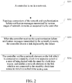
- Fig. 2 is a flowchart of processing a failure for a clock and time synchronization network according to an embodiment.
- a controller is set in the synchronization network, as shown in Fig. 3 ; in S202, topology connections of the clock/time synchronization network and clock/time synchronization failure notification messages transmitted by various stages of network elements are acquired via the controller; in S203, when the controller receives the clock/time failure notification messages transmitted by the network elements, the controller detects a link impacted by the failure; and
- the controller notifies a network element on the link which is connected to a standby clock/time source to switch to a state of being locked with the standby clock/time source, and notifies the network element on the link which is not connected to the standby clock/time source to switch to a clock/time holding state.
- the controller in the clock/time synchronization network which can communicate with various stages of network elements and can acquire topology connections of the network is achieved.
- the controller can directly notify a network element which is connected to a standby clock/time source to switch to a state of being locked with the standby clock/time source, which compared with transferring a notification message network element by network element until a network element which can be locked with the standby clock/time source is found in the related technology, can more quickly acquire the standby clock/time source.
- the controller when a synchronization failure occurs in the network, the controller directly notifies the network element which is not connected to the standby clock to switch to a clock/time holding state, so that the problem of transfer of the clock/time error in the related technology can be constrained once it is found, which avoids diffusion of the clock/time error among the network nodes.
- clock/time represents clock in the clock synchronization network and represents time in the time synchronization network.
- the above embodiment further comprises the following steps. after learning that a network element which is connected to the standby clock/time source selects the standby clock/time source as its clock/time source, the controller notifies a network element in a holding state that is adjacent to the network element which selects the standby clock/time source to performing clock/time locking with the network element which selects the standby clock/time source; and after learning that the network element in the holding state selects an adjacent clock/time source thereof as its clock/time source, if it is judged that the network element in the holding state is not a network element which transmits a synchronization failure notification message, the controller continues to notify the network element in the holding state which is adjacent to the network element to perform clock/time locking with the network element.
- the network element which is connected to the standby clock/time source selects the standby clock/time source as its own clock/time source
- the network element notifies a network element in a clock/time holding state which is adjacent to the network element to perform clock/time locking with the network element; and after the network element in a holding state selects a clock/time source and in a case of determining that it does not transmit a failure notification message to the controller, the network element continues to notify the network element in a clock/time holding state which is adjacent to the network element to performing clock/time locking with the network element.
- the network element in the network receives a notification of implementing clock/time locking with its adjacent network element from the controller, in order to avoid the network element and a network element having the same clock/time quality level from being locked with each other, in the above embodiment, after receiving a notification of switching to a state of being locked with the standby clock/time source which is transmitted by the controller, the network element which is connected to the standby clock/time source acquires a quality level of the standby clock/time source, and if the quality level of the standby clock/time source is the same as a clock/time quality level of itself, a locking flow is not performed, and if the quality level of the standby clock/time source is greater than the clock/time quality level of itself, locking with the standby clock/time source is performed; and after receiving a notification of switching to a state of being locked with a clock/time source of its adjacent network element which is transmitted by the controller, the network element in the holding state acquires a quality level of the clock/time source of the adjacent network element, and if the
- the network element 2 finds that a reference clock is lost, and immediately transmits a clock synchronization failure notification to a controller while entering a clock holding state.
- the controller After receiving the synchronization failure notification transmitted by the network element 2, the controller judges that a link impacted by the failure is network element 2 - network element 3 - network element 4 - network element 5, wherein the network element 5 has a standby clock source which is connected therewith, i.e., a clock of network element 6, and the network elements 3 and 4 do not have a standby clock source which is connected therewith; the controller notifies the network element 5 to lock with the clock of the network element 6, and notifies the network elements 2, 3 and 4 to switch to a clock holding state; after receiving a message of selecting the clock of the network element 6 which is transmitted by the network element 5, the controller notifies the network element 4 to lock with the clock of the network element 5; after receiving a message of selecting the clock of the network element 5 which is transmitted by the network element 4, the controller notifies the network element 3 to lock with the clock of the network element 4; and after receiving a message of selecting the clock of the network element 4 which is transmitted by the network element 3, the controller notifies the network element 2 to lock with
- the network element 2 finds that a reference clock is lost, and immediately transmits a clock synchronization failure notification to a controller while entering a clock holding state.
- the controller After receiving the synchronization failure notification transmitted by the network element 2, the controller judges that a link impacted by the failure is network element 2 - network element 3 - network element 4 - network element 5, wherein the network element 5 has a standby clock source which is connected therewith, i.e., a clock of network element 6, and the network elements 3 and 4 do not have a standby clock source which is connected therewith; the controller notifies the network element 5 to lock with the clock of the network element 6, and notifies the network elements 2, 3 and 4 to switch to a clock holding state; after selecting the clock of the network element 6, the network element 5 notifies the network element 4 to lock with its own clock; after selecting the clock of the network element 5, the network element 4 notifies the network element 3 to lock with its own clock; and after selecting the clock of the network element 4, the network element 3 notifies the network element 2 to lock with its own clock.
- the network element 5 has a standby clock source which is connected therewith, i.e., a clock of network element 6, and the network elements 3
- the network element 2 finds that a reference clock is lost, and immediately transmits a clock synchronization failure notification to a controller while entering a clock holding state.
- the controller After receiving the synchronization failure notification transmitted by the network element 2, the controller judges that a link impacted by the failure is network element 2 - network element 3 - network element 4 - network element 5, wherein the network element 5 has a standby clock source which is connected therewith, i.e., a clock of network element 6, and the network elements 3 and 4 do not have the standby clock source which is connected therewith; the controller notifies the network element 5 to lock with the clock of the network element 6, and notifies the network elements 2, 3 and 4 to switch to a clock holding state; the controller notifies the network element 4 to lock with the clock of the network element 5 after a preset time t; the controller notifies the network element 3 to lock with the clock of the network element 4 after the preset time t; and the controller notifies the network element 2 to lock with the clock of the network element 3 after the preset time t.
- the network element 5 has a standby clock source which is connected therewith, i.e., a clock of network element 6, and the network elements 3
- the preset time t is required to be no less than a minimum time which is generally required by the network element to complete time locking.
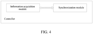
- the system comprises a controller including an information acquisition module and a synchronization module, wherein the information acquisition module is configured to acquire topology connections of the clock/time synchronization network and clock/time synchronization failure notification messages transmitted by various stages of network elements, and transmit the synchronization failure messages to the synchronization module; and the synchronization module is configured to detect a link impacted by the failure after receiving the synchronization failure notification messages transmitted by the network elements, and notify a network element on the link which is connected to a standby clock/time source to switch to a state of being locked with the standby clock/time source and notify the network element on the link which is not connected to the standby clock/time source to switch to a clock/time holding state.
- the controller can directly notify a network element which is connected to a standby clock/time source to switch to a state of being locked with the standby clock/time source, which compared with transferring a message network element by network element until a network element which can be locked with the standby clock/time source is found in the related technology, can more quickly acquire the standby clock/time source.
- the controller directly notifies the network element which is not connected to the standby clock to switch to a clock/time holding state, so that the problem of transfer of the clock/time error in the related technology can be constrained once it is found, which avoids diffusion of the clock/time error among the network nodes.
- the above system may further comprise network elements on the link impacted by the failure, wherein the network elements comprise a network element which is connected to the standby clock/time source and a network element which is not connected to the standby clock/time source, wherein the network element which is connected to the standby clock/time source is configured to after receiving a notification from the controller, complete clock/time locking with the standby clock/time source, and after selecting the standby clock/time source as its own clock/time source, notify its adjacent network element in a clock holding state on the link which is not connected to the standby clock/time source to perform clock/time locking therewith; and the network elements which is not connected to the standby clock/time source is configured to after receiving the notification from the controller, enter a clock/time holding state; and after selecting a clock/time source, if it is judged that it does not transmit a synchronization failure notification message to the controller, continue to notify its adjacent network element in
- the network element which is connected to the standby clock/time source is further configured to after receiving a notification of switching to a state of being locked with the standby clock/time source which is transmitted by the controller, acquire a quality level of the standby clock/time source, and if the quality level of the standby clock/time source is the same as a clock/time quality level of itself, not performing a locking flow, and if the quality level of the standby clock/time source is greater than the clock/time quality level of itself, performing locking with the standby clock/time source; and the network element which is not connected to the standby clock/time source is further configured to after receiving a notification of switching to a state of being locked with a clock/time source of its adjacent network element which is transmitted by the controller, acquire a quality level of the clock/time source of the adjacent network
Landscapes
- Engineering & Computer Science (AREA)
- Computer Networks & Wireless Communication (AREA)
- Signal Processing (AREA)
- Synchronisation In Digital Transmission Systems (AREA)
- Data Exchanges In Wide-Area Networks (AREA)
Claims (8)
- Verfahren zum Verarbeiten einer Synchronisationsstörung für ein Takt- und Zeitsynchronisierungsnetzwerk, Folgendes umfassend:Bereitstellen einer Steuerung in einem Takt-/Zeitsynchronisierungsnetzwerk (S201) und Erfassen, durch die Steuerung, von Topologieverbindungen des Netzwerks und Takt-/Zeit-Synchronisierungsstörungsbenachrichtigungsmeldungen, die durch Netzwerkelemente verschiedener Stufen übermittelt werden, wenn die Netzwerkelemente selbst eine Störung erkennen (S202);wenn die Steuerung die Takt-/Zeit-Synchronisierungsstörungsbenachrichtigungsmeldungen empfängt, die durch die Netzwerkelemente übertragen werden, Erkennen einer durch die Störung betroffenen Verknüpfung in den Topologieverbindungen des Netzwerks (S203) durch die Steuerung; undBenachrichtigen eines Netzwerkelements durch die Steuerung, das mit einer Standby-Takt/Zeit-Quelle auf der Verknüpfung verbunden ist, in einen Blockierzustand, der mit der Standby-Takt/Zeit-Quelle synchronisiert ist, umzuschalten, und Benachrichtigen eines Netzwerkelements durch die Steuerung, das nicht mit einer Standby-Takt/Zeit-Quelle auf der Verknüpfung verbunden ist, in einen Takt/Zeit-Haltezustand (S204) umzuschalten,wobei das Erfassen der Topologieverbindungen des Netzwerks durch die Steuerung Folgendes umfasst:die Netzwerkelemente werden durch die Steuerung nach ihren assoziierten Verknüpfungen abgefragt, oder die Netzwerkelemente berichten aktiv ihre assoziierten Verknüpfungen an die Steuerung,die Standby-Takt/Zeit-Quelle ist eine andere Takt/Zeit-Quelle als eine Takt/Zeit-Quelle, die aktuell mit dem Netzwerkelement synchronisiert ist.
- Verfahren nach Anspruch 1, ferner Folgendes umfassend:nach dem Lernen, dass das Netzwerkelement, das mit der Standby-Takt/Zeit-Quelle verbunden ist, die Standby-Takt/Zeit-Quelle als Takt/Zeit-Quelle selbst auswählt, Benachrichtigen durch die Steuerung eines Netzwerkelements in einem Haltezustand, das an das Netzwerkelement angrenzt, das die Takt/Zeit-Quelle auswählt, eine Takt/Zeit-Blockierung mit dem Netzwerkelement durchzuführen, das die Takt/Zeit-Quelle auswählt; undnach dem Lernen, dass das Netzwerkelement in dem Haltezustand eine angrenzende Takt/Zeit-Quelle des Netzwerkelements in dem Haltezustand als Takt/Zeit-Quelle selbst auswählt, falls beurteilt ist, dass das Netzwerkelement in dem Haltezustand kein Netzwerkelement ist, das eine Synchronisierungsstörungsbenachrichtigungsmeldung übermittelt, Fortführen der Steuerung, ein Netzwerkelement in einem Haltezustand zu benachrichtigen, das an das Netzwerkelement angrenzt, um die Takt/Zeit-Blockierung mit dem Netzwerkelement durchzuführen.
- Verfahren nach Anspruch 1, ferner Folgendes umfassend:nach dem Benachrichtigen des Netzwerkelements, das mit der Standby-Takt/Zeit-Quelle auf der Verknüpfung verbunden ist, in den Takt/Zeit-Blockierzustand umzuschalten, der mit der Standby-Takt/Zeit-Quelle synchronisiert ist, und dem Benachrichtigen des Netzwerkelements, das nicht mit der Standby-Takt/Zeit-Quelle auf der Verknüpfung verbunden ist, in den Takt/Zeit-Haltezustand umzuschalten, Benachrichtigen durch die Steuerung eines Netzwerkelements in einem Haltezustand nach einem vorbestimmten Zeitintervall, das an das Netzwerkelement angrenzt, das mit der Standby-Takt/Zeit-Quelle verbunden ist, um ein Takt/Zeit-Blockieren mit dem Netzwerkelement durchzuführen, das mit der Standby-Takt/Zeit-Quelle verbunden ist; undnach dem Benachrichtigen des Netzwerkelements in dem Zeit-Haltezustand, ein Takt/Zeit-Blockieren mit dem angrenzenden Netzwerkelement des Netzwerkelements in dem Zeit-Haltezustand durchzuführen, falls beurteilt ist, dass das Netzwerkelement in dem Haltezustand kein Netzwerkelement ist, das eine Fehlerbenachrichtigungmeldung übermittelt, Fortführen der Steuerung, ein Netzwerkelement in einem Haltezustand nach dem vorbestimmten Zeitintervall zu benachrichtigen, das an das Netzwerkelement angrenzt, um die Takt/Zeit-Blockierung durchzuführen.
- Verfahren nach einem der Ansprüche 2 bis 3, das ferner Folgendes umfasst:nach dem Empfangen einer Benachrichtigung zum Umschalten in den Takt/Zeit-Blockierzustand, der mit der durch die Steuerung übermittelten Standby-Takt/Zeit-Quelle synchronisiert ist, Erfassen einer Qualitätsstufe der Standby-Takt/Zeit-Quelle durch das Netzwerkelement, das mit der Standby-Takt/Zeit-Quelle verbunden ist, und falls die Qualitätsstufe der Standby-Takt/Zeit-Quelle die gleiche ist wie die eigene Takt/Zeit-Qualitätsstufe, kein Durchführen eines Blockierflusses, und falls die Qualitätsstufe der Standby-Takt/Zeit-Quelle größer als die eigene Takt/Zeit-Qualitätsstufe ist, Implementieren von Blockieren mit der Standby-Takt/Zeit-Quelle; undnach dem Empfangen einer Benachrichtigung zum Umschalten, um mit einer Takt-Zeit-Quelle des angrenzenden Netzwerkelements des Netzwerkelements in dem Haltezustand, das durch die Steuerung übermittelt wird, blockiert zu sein, Erfassen durch das Netzwerkelement in dem Haltezustand einer Qualitätsstufe der Takt/Zeit-Quelle des angrenzenden Netzwerkelements, und falls die Qualitätsstufe einer Takt/Zeit-Quelle des Netzwerkelements, das den Takt/die Zeit auswählt, die gleiche ist wie die eigene Takt/Zeit-Qualitätsstufe, kein Durchführen eines Blockierflusses; und falls die Qualitätsstufe der Takt/Zeit-Quelle eines angrenzenden Takt/Zeit-Netzwerkelements größer als die eigene Takt/Zeit-Qualitätsstufe ist, Implementieren des Takt/Zeit-Blockierens mit dem angrenzenden Takt/Zeit-Netzwerkelement.
- System zum Verarbeiten einer Synchronisationsstörung für ein Takt- und Zeitsynchronisierungsnetzwerk, eine Steuerung umfassend, die ein Informationserfassungsmodul und ein Synchronisationsmodul beinhaltet, wobei
das Informationserfassungsmodul dazu konfiguriert ist, Topologieverbindungen eines Takt/Zeit-Synchronisationsnetzwerks und Takt/Zeit-Synchronisierungsstörungsbenachrichtigungsmeldungen, die durch Netzwerkelemente verschiedener Stufen übermittelt werden, wenn die Netzwerkelemente selbst eine Störung erkennen, zu erfassen und die Synchronisierungsstörungsmeldungen an das Synchronisationsmodul zu übermitteln; und
das Synchronisationsmodul dazu konfiguriert ist, nach dem Empfangen der Synchronisierungsstörungsbenachrichtigungsmeldungen, die durch die Netzwerkelemente übermittelt werden, eine Verknüpfung zu erkennen, die durch die Störung in den Topologieverknüpfungen betroffen ist und ein Netzwerkelement zu benachrichtigen, das mit einer Standby-Takt/Zeit-Quelle auf der Verknüpfung verbunden ist, um in einen Takt/Zeit-Zustand umzuschalten, der mit der Standby-Takt/Zeit-Quelle synchronisiert ist, und ein Netzwerkelement zu benachrichtigen, das nicht mit einer Standby-Takt/Zeit-Quelle auf der Verknüpfung verbunden ist, in einen Takt/Zeit-Haltezustand umzuschalten,
wobei das Erfassen der Topologieverbindungen des Takt/Zeit-Synchronisierungsnetzwerks Folgendes umfasst:die Netzwerkelemente werden durch das Informationserfassungsmodul nach ihren assoziierten Verknüpfungen abgefragt, oder die Netzwerkelemente berichten aktiv ihre assoziierten Verknüpfungen an das Informationserfassungsmodul,die Standby-Takt/Zeit-Quelle ist eine andere Takt/Zeit-Quelle als eine Takt/Zeit-Quelle, die aktuell mit dem Netzwerkelement synchronisiert ist. - System nach Anspruch 5 wobei
das Synchronisationsmodul ferner dazu konfiguriert ist, nach dem Lernen, dass das Netzwerkelement, das mit der Standby-Takt/Zeit-Quelle verbunden ist, die Standby-Takt/Zeit-Quelle als Takt/Zeit-Quelle selbst auswählt, ein Netzwerkelement in einem Haltezustand zu benachrichtigen, das an das Netzwerkelement angrenzt, das die Takt/Zeit-Quelle auswählt, um eine Takt/Zeit-Blockierung mit dem Netzwerkelement durchzuführen, das die Takt/Zeit-Quelle auswählt;
nach dem Lernen, dass das Netzwerkelement in dem Haltezustand eine angrenzende Takt/Zeit-Quelle des Netzwerkelements in dem Haltezustand als Takt/Zeit-Quelle selbst auswählt, falls beurteilt ist, dass das Netzwerkelement in dem Haltezustand kein Netzwerkelement ist, das eine Synchronisierungsstörungsbenachrichtigungsmeldung übermittelt, das Benachrichtigen eines Netzwerkelements in einem Haltezustand, das an das Netzwerkelement angrenzt, fortgeführt wird, um die Takt/Zeit-Blockierung mit dem Netzwerkelement zu implementieren. - System nach Anspruch 5 wobei
das Synchronisationsmodul ferner dazu konfiguriert ist, nach dem Benachrichtigen des Netzwerkelements, das mit der Standby-Takt/Zeit-Quelle auf der Verknüpfung verbunden ist, in den Takt/Zeit-Blockierzustand umzuschalten, der mit der Standby-Takt/Zeit-Quelle synchronisiert ist, und dem Benachrichtigen des Netzwerkelements, das nicht mit der Standby-Takt/Zeit-Quelle auf der Verknüpfung verbunden ist, in den Takt/Zeit-Haltezustand umzuschalten, ein Netzwerkelement in einem Haltezustand nach einem vorbestimmten Zeitintervall zu benachrichtigen, das an das Netzwerkelement angrenzt, das mit der Standby-Takt/Zeit-Quelle verbunden ist, um ein Takt/Zeit-Blockieren mit dem Netzwerkelement durchzuführen, das mit der Standby-Takt/Zeit-Quelle verbunden ist; und nach dem Benachrichtigen des Netzwerkelements in dem Zeit-Haltezustand, ein Takt/Zeit-Blockieren mit dem angrenzenden Netzwerkelement des Netzwerkelements in dem Zeit-Haltezustand durchzuführen, falls beurteilt ist, dass das Netzwerkelement in dem Haltezustand kein Netzwerkelement ist, das eine Fehlerbenachrichtigungmeldung übermittelt, Fortführen, ein Netzwerkelement in einem Haltezustand nach dem vorbestimmten Zeitintervall zu benachrichtigen, das an das Netzwerkelement angrenzt, um die Takt/Zeit-Blockierung durchzuführen. - System nach einem der Ansprüche 6 bis 7, ferner Netzwerkelemente umfassend, die durch die Störung auf der Verknüpfung betroffen sind, wobei die Netzwerkelemente das Netzwerkelement, das mit der Standby-Takt/Zeit-Quelle verbunden ist und das Netzwerkelement umfassen, das nicht mit der Standby-Takt/Zeit-Quelle verbunden ist, wobei
das Netzwerkelement, das mit der Standby-Takt/Zeit-Quelle verbunden ist, dazu konfiguriert ist, nach dem Empfangen einer Benachrichtigung zum Umschalten in den Takt/Zeit-Blockierzustand, der mit der durch die Steuerung übermittelten Standby-Takt/Zeit-Quelle synchronisiert ist, eine Qualitätsstufe der Standby-Takt/Zeit-Quelle durch das Netzwerkelement zu erfassen, das mit der Standby-Takt/Zeit-Quelle verbunden ist, und falls die Qualitätsstufe der Standby-Takt/Zeit-Quelle die gleiche ist wie die eigene Takt/Zeit-Qualitätsstufe, keinen Blockierfluss durchzuführen, und falls die Qualitätsstufe der Standby-Takt/Zeit-Quelle größer als die eigene Takt/Zeit-Qualitätsstufe ist, das Blockieren der mit der Standby-Takt/Zeit-Quelle synchronisierten Takt/Zeit durchzuführen;
und
das Netzwerkelement, das nicht mit der Standby-Takt/Zeit-Quelle verbunden ist, dazu konfiguriert ist, nach dem Empfangen einer durch die Steuerung übermittelten Benachrichtigung zum Umschalten, um mit einer Takt/Zeit-Quelle des angrenzenden Netzwerkelements des Netzwerkelements, das nicht mit der Standby-Takt/Zeit-Quelle verbunden ist, blockiert zu sein, eine Qualitätsstufe der Takt/Zeit-Quelle des angrenzenden Netzwerkelements zu erfassen, und falls die Qualitätsstufe einer Takt/Zeit-Quelle eines Netzwerkelements, das den Takt/die Zeit auswählt, gleich der eigenen Takt/Zeit-Qualitätsstufe ist, keinen Blockierfluss durchzuführen; und falls die Qualitätsstufe der Takt/Zeit-Quelle eines angrenzenden Takt/Zeit-Netzwerkelements größer als die eigene Takt/Zeit-Qualitätsstufe ist, das Takt/Zeit-Blockieren mit dem angrenzenden Takt/Zeit-Netzwerkelement durchzuführen.
Applications Claiming Priority (2)
| Application Number | Priority Date | Filing Date | Title |
|---|---|---|---|
| CN201410166755.9A CN105024841B (zh) | 2014-04-23 | 2014-04-23 | 一种时钟和时间同步网络的同步故障处理方法和系统 |
| PCT/CN2014/087103 WO2015161621A1 (zh) | 2014-04-23 | 2014-09-22 | 一种时钟和时间同步网络的同步故障处理方法和系统 |
Publications (3)
| Publication Number | Publication Date |
|---|---|
| EP3121996A1 EP3121996A1 (de) | 2017-01-25 |
| EP3121996A4 EP3121996A4 (de) | 2017-03-29 |
| EP3121996B1 true EP3121996B1 (de) | 2019-02-27 |
Family
ID=54331695
Family Applications (1)
| Application Number | Title | Priority Date | Filing Date |
|---|---|---|---|
| EP14890086.3A Active EP3121996B1 (de) | 2014-04-23 | 2014-09-22 | Synchronisationsstörungsverarbeitungsverfahren und system für ein takt- und zeitsynchronisierungsnetzwerk |
Country Status (3)
| Country | Link |
|---|---|
| EP (1) | EP3121996B1 (de) |
| CN (1) | CN105024841B (de) |
| WO (1) | WO2015161621A1 (de) |
Families Citing this family (11)
| Publication number | Priority date | Publication date | Assignee | Title |
|---|---|---|---|---|
| CN106712923B (zh) * | 2015-11-12 | 2020-06-23 | 中国移动通信集团公司 | 一种同步网络恢复方法及装置 |
| CN106921509B (zh) * | 2015-12-28 | 2020-07-10 | 中兴通讯股份有限公司 | 一种全网时钟同步管理的方法及装置 |
| CN105629107B (zh) * | 2015-12-30 | 2018-08-31 | 北京四方继保自动化股份有限公司 | 一种厂站时钟同步故障在线监测方法 |
| CN105703867B (zh) * | 2016-01-07 | 2018-05-08 | 烽火通信科技股份有限公司 | 适用于时间同步网的快速部署系统及方法 |
| CN108134644B (zh) * | 2016-12-01 | 2019-10-22 | 中国移动通信有限公司研究院 | 同步方法、装置、同步设备及系统 |
| CN107330994B (zh) * | 2017-06-30 | 2019-11-26 | 联想(北京)有限公司 | 运行状态的切换时刻获取方法及电子设备 |
| CN114080017B (zh) * | 2020-08-20 | 2025-10-03 | 华为技术有限公司 | 处理时间同步故障的方法、装置及系统 |
| EP4470289A1 (de) * | 2022-01-27 | 2024-12-04 | Qualcomm Incorporated | Zeitsynchronisationsänderungsangaben |
| CN115865247B (zh) * | 2022-03-21 | 2025-07-15 | 中兴通讯股份有限公司 | 时钟同步方法、设备和存储介质 |
| CN117062207A (zh) * | 2022-05-06 | 2023-11-14 | 华为技术有限公司 | 通信方法及装置 |
| CN115134035A (zh) * | 2022-08-30 | 2022-09-30 | 深圳市英特瑞半导体科技有限公司 | 基于同步以太网的破环方法、装置、设备及存储介质 |
Family Cites Families (6)
| Publication number | Priority date | Publication date | Assignee | Title |
|---|---|---|---|---|
| GB2341749A (en) * | 1998-09-19 | 2000-03-22 | Nokia Telecommunications Oy | Digital network synchronisation |
| JP2001244918A (ja) * | 2000-02-28 | 2001-09-07 | Fujitsu Ltd | ネットワーク装置 |
| CN100589433C (zh) * | 2005-10-25 | 2010-02-10 | 华为技术有限公司 | 通过分组网络提供时钟同步的方法和系统 |
| CN102685781B (zh) * | 2011-03-07 | 2014-07-30 | 北京邮电大学 | 主备时间源自动保护倒换方法 |
| CN102208958B (zh) * | 2011-07-04 | 2012-12-19 | 瑞斯康达科技发展股份有限公司 | 同步以太网的时钟同步及同步信息收发方法、装置和设备 |
| US20130336117A1 (en) * | 2012-06-15 | 2013-12-19 | Desmond Yan | Distributed processing scheme to support ieee 1588 ptp over multiple ports spanning a lag |
-
2014
- 2014-04-23 CN CN201410166755.9A patent/CN105024841B/zh active Active
- 2014-09-22 EP EP14890086.3A patent/EP3121996B1/de active Active
- 2014-09-22 WO PCT/CN2014/087103 patent/WO2015161621A1/zh not_active Ceased
Non-Patent Citations (1)
| Title |
|---|
| None * |
Also Published As
| Publication number | Publication date |
|---|---|
| WO2015161621A1 (zh) | 2015-10-29 |
| EP3121996A4 (de) | 2017-03-29 |
| CN105024841A (zh) | 2015-11-04 |
| CN105024841B (zh) | 2019-08-27 |
| EP3121996A1 (de) | 2017-01-25 |
Similar Documents
| Publication | Publication Date | Title |
|---|---|---|
| EP3121996B1 (de) | Synchronisationsstörungsverarbeitungsverfahren und system für ein takt- und zeitsynchronisierungsnetzwerk | |
| EP2045965B1 (de) | Verfahren, vorrichtung und kommunikationsnetz zur überwachung eines betriebsmittelzustands | |
| US9544223B2 (en) | Communication system, control apparatus, method for controlling same, and program | |
| JP5120097B2 (ja) | 時間同期システムおよび時間同期装置 | |
| JP2014520419A (ja) | 高可用性グランド・マスタ・クロックを実装するためのネットワークおよび方法 | |
| CN109462533B (zh) | 链路切换方法、链路冗余备份网络和计算机可读存储介质 | |
| KR20190038255A (ko) | 시분할 이중화 방식을 사용하는 분산 안테나 시스템의 tdd 서브-시스템 | |
| CN113422623B (zh) | 一种管理方法、系统、装置、电子设备及存储介质 | |
| JP6275323B2 (ja) | 中継装置および通信システム | |
| CN102158335B (zh) | 时间同步端口的处理方法及装置 | |
| US9197441B2 (en) | Method and system for service protection | |
| US20180048488A1 (en) | Ethernet Ring Protection Switching Method and Node | |
| CN105024798A (zh) | 一种时间同步的方法及装置 | |
| WO2017058183A1 (en) | Network nodes in a ring network | |
| CN103607293A (zh) | 一种流量保护方法及设备 | |
| KR20230119215A (ko) | 클록 소스 선택 방법 및 장치 | |
| CN102739389A (zh) | 一种分组传送网中多gm设备时间同步的方法及系统 | |
| CN102739535A (zh) | 一种线卡离线的保护方法和系统 | |
| US11223965B2 (en) | Method and apparatus for controlling network sensors | |
| CN111373700B (zh) | 通信系统、被控制设备以及通信系统的控制方法 | |
| JP5697071B2 (ja) | ネットワークシステム及びその障害回復方法 | |
| EP2698949B1 (de) | Verfahren und system zum einstellen der erkennungsrahmen-zeitüberschreitungsdauer von ethernet-knoten | |
| CN111344962A (zh) | 光网络单元的网络接口切换方法及光网络单元 | |
| CN114173367B (zh) | 时间同步路径保护方法、装置及可读存储介质 | |
| CN103051407A (zh) | 时钟保护方法、系统和相关普通时钟设备 |
Legal Events
| Date | Code | Title | Description |
|---|---|---|---|
| STAA | Information on the status of an ep patent application or granted ep patent |
Free format text: STATUS: THE INTERNATIONAL PUBLICATION HAS BEEN MADE |
|
| PUAI | Public reference made under article 153(3) epc to a published international application that has entered the european phase |
Free format text: ORIGINAL CODE: 0009012 |
|
| STAA | Information on the status of an ep patent application or granted ep patent |
Free format text: STATUS: REQUEST FOR EXAMINATION WAS MADE |
|
| 17P | Request for examination filed |
Effective date: 20161019 |
|
| AK | Designated contracting states |
Kind code of ref document: A1 Designated state(s): AL AT BE BG CH CY CZ DE DK EE ES FI FR GB GR HR HU IE IS IT LI LT LU LV MC MK MT NL NO PL PT RO RS SE SI SK SM TR |
|
| AX | Request for extension of the european patent |
Extension state: BA ME |
|
| A4 | Supplementary search report drawn up and despatched |
Effective date: 20170227 |
|
| RIC1 | Information provided on ipc code assigned before grant |
Ipc: H04L 12/24 20060101AFI20170221BHEP |
|
| DAX | Request for extension of the european patent (deleted) | ||
| STAA | Information on the status of an ep patent application or granted ep patent |
Free format text: STATUS: EXAMINATION IS IN PROGRESS |
|
| 17Q | First examination report despatched |
Effective date: 20180212 |
|
| GRAP | Despatch of communication of intention to grant a patent |
Free format text: ORIGINAL CODE: EPIDOSNIGR1 |
|
| STAA | Information on the status of an ep patent application or granted ep patent |
Free format text: STATUS: GRANT OF PATENT IS INTENDED |
|
| RIC1 | Information provided on ipc code assigned before grant |
Ipc: H04L 12/24 20060101AFI20180924BHEP |
|
| INTG | Intention to grant announced |
Effective date: 20181012 |
|
| GRAS | Grant fee paid |
Free format text: ORIGINAL CODE: EPIDOSNIGR3 |
|
| GRAA | (expected) grant |
Free format text: ORIGINAL CODE: 0009210 |
|
| STAA | Information on the status of an ep patent application or granted ep patent |
Free format text: STATUS: THE PATENT HAS BEEN GRANTED |
|
| AK | Designated contracting states |
Kind code of ref document: B1 Designated state(s): AL AT BE BG CH CY CZ DE DK EE ES FI FR GB GR HR HU IE IS IT LI LT LU LV MC MK MT NL NO PL PT RO RS SE SI SK SM TR |
|
| REG | Reference to a national code |
Ref country code: GB Ref legal event code: FG4D |
|
| REG | Reference to a national code |
Ref country code: CH Ref legal event code: EP |
|
| REG | Reference to a national code |
Ref country code: AT Ref legal event code: REF Ref document number: 1102943 Country of ref document: AT Kind code of ref document: T Effective date: 20190315 |
|
| REG | Reference to a national code |
Ref country code: IE Ref legal event code: FG4D |
|
| REG | Reference to a national code |
Ref country code: DE Ref legal event code: R096 Ref document number: 602014042136 Country of ref document: DE |
|
| REG | Reference to a national code |
Ref country code: NL Ref legal event code: MP Effective date: 20190227 |
|
| REG | Reference to a national code |
Ref country code: LT Ref legal event code: MG4D |
|
| PG25 | Lapsed in a contracting state [announced via postgrant information from national office to epo] |
Ref country code: LT Free format text: LAPSE BECAUSE OF FAILURE TO SUBMIT A TRANSLATION OF THE DESCRIPTION OR TO PAY THE FEE WITHIN THE PRESCRIBED TIME-LIMIT Effective date: 20190227 Ref country code: NL Free format text: LAPSE BECAUSE OF FAILURE TO SUBMIT A TRANSLATION OF THE DESCRIPTION OR TO PAY THE FEE WITHIN THE PRESCRIBED TIME-LIMIT Effective date: 20190227 Ref country code: FI Free format text: LAPSE BECAUSE OF FAILURE TO SUBMIT A TRANSLATION OF THE DESCRIPTION OR TO PAY THE FEE WITHIN THE PRESCRIBED TIME-LIMIT Effective date: 20190227 Ref country code: NO Free format text: LAPSE BECAUSE OF FAILURE TO SUBMIT A TRANSLATION OF THE DESCRIPTION OR TO PAY THE FEE WITHIN THE PRESCRIBED TIME-LIMIT Effective date: 20190527 Ref country code: SE Free format text: LAPSE BECAUSE OF FAILURE TO SUBMIT A TRANSLATION OF THE DESCRIPTION OR TO PAY THE FEE WITHIN THE PRESCRIBED TIME-LIMIT Effective date: 20190227 Ref country code: PT Free format text: LAPSE BECAUSE OF FAILURE TO SUBMIT A TRANSLATION OF THE DESCRIPTION OR TO PAY THE FEE WITHIN THE PRESCRIBED TIME-LIMIT Effective date: 20190627 |
|
| PG25 | Lapsed in a contracting state [announced via postgrant information from national office to epo] |
Ref country code: HR Free format text: LAPSE BECAUSE OF FAILURE TO SUBMIT A TRANSLATION OF THE DESCRIPTION OR TO PAY THE FEE WITHIN THE PRESCRIBED TIME-LIMIT Effective date: 20190227 Ref country code: RS Free format text: LAPSE BECAUSE OF FAILURE TO SUBMIT A TRANSLATION OF THE DESCRIPTION OR TO PAY THE FEE WITHIN THE PRESCRIBED TIME-LIMIT Effective date: 20190227 Ref country code: BG Free format text: LAPSE BECAUSE OF FAILURE TO SUBMIT A TRANSLATION OF THE DESCRIPTION OR TO PAY THE FEE WITHIN THE PRESCRIBED TIME-LIMIT Effective date: 20190527 Ref country code: LV Free format text: LAPSE BECAUSE OF FAILURE TO SUBMIT A TRANSLATION OF THE DESCRIPTION OR TO PAY THE FEE WITHIN THE PRESCRIBED TIME-LIMIT Effective date: 20190227 Ref country code: GR Free format text: LAPSE BECAUSE OF FAILURE TO SUBMIT A TRANSLATION OF THE DESCRIPTION OR TO PAY THE FEE WITHIN THE PRESCRIBED TIME-LIMIT Effective date: 20190528 Ref country code: IS Free format text: LAPSE BECAUSE OF FAILURE TO SUBMIT A TRANSLATION OF THE DESCRIPTION OR TO PAY THE FEE WITHIN THE PRESCRIBED TIME-LIMIT Effective date: 20190627 |
|
| REG | Reference to a national code |
Ref country code: AT Ref legal event code: MK05 Ref document number: 1102943 Country of ref document: AT Kind code of ref document: T Effective date: 20190227 |
|
| PG25 | Lapsed in a contracting state [announced via postgrant information from national office to epo] |
Ref country code: RO Free format text: LAPSE BECAUSE OF FAILURE TO SUBMIT A TRANSLATION OF THE DESCRIPTION OR TO PAY THE FEE WITHIN THE PRESCRIBED TIME-LIMIT Effective date: 20190227 Ref country code: SK Free format text: LAPSE BECAUSE OF FAILURE TO SUBMIT A TRANSLATION OF THE DESCRIPTION OR TO PAY THE FEE WITHIN THE PRESCRIBED TIME-LIMIT Effective date: 20190227 Ref country code: CZ Free format text: LAPSE BECAUSE OF FAILURE TO SUBMIT A TRANSLATION OF THE DESCRIPTION OR TO PAY THE FEE WITHIN THE PRESCRIBED TIME-LIMIT Effective date: 20190227 Ref country code: AL Free format text: LAPSE BECAUSE OF FAILURE TO SUBMIT A TRANSLATION OF THE DESCRIPTION OR TO PAY THE FEE WITHIN THE PRESCRIBED TIME-LIMIT Effective date: 20190227 Ref country code: ES Free format text: LAPSE BECAUSE OF FAILURE TO SUBMIT A TRANSLATION OF THE DESCRIPTION OR TO PAY THE FEE WITHIN THE PRESCRIBED TIME-LIMIT Effective date: 20190227 Ref country code: DK Free format text: LAPSE BECAUSE OF FAILURE TO SUBMIT A TRANSLATION OF THE DESCRIPTION OR TO PAY THE FEE WITHIN THE PRESCRIBED TIME-LIMIT Effective date: 20190227 Ref country code: IT Free format text: LAPSE BECAUSE OF FAILURE TO SUBMIT A TRANSLATION OF THE DESCRIPTION OR TO PAY THE FEE WITHIN THE PRESCRIBED TIME-LIMIT Effective date: 20190227 Ref country code: EE Free format text: LAPSE BECAUSE OF FAILURE TO SUBMIT A TRANSLATION OF THE DESCRIPTION OR TO PAY THE FEE WITHIN THE PRESCRIBED TIME-LIMIT Effective date: 20190227 |
|
| REG | Reference to a national code |
Ref country code: DE Ref legal event code: R097 Ref document number: 602014042136 Country of ref document: DE |
|
| PG25 | Lapsed in a contracting state [announced via postgrant information from national office to epo] |
Ref country code: SM Free format text: LAPSE BECAUSE OF FAILURE TO SUBMIT A TRANSLATION OF THE DESCRIPTION OR TO PAY THE FEE WITHIN THE PRESCRIBED TIME-LIMIT Effective date: 20190227 Ref country code: PL Free format text: LAPSE BECAUSE OF FAILURE TO SUBMIT A TRANSLATION OF THE DESCRIPTION OR TO PAY THE FEE WITHIN THE PRESCRIBED TIME-LIMIT Effective date: 20190227 |
|
| PG25 | Lapsed in a contracting state [announced via postgrant information from national office to epo] |
Ref country code: AT Free format text: LAPSE BECAUSE OF FAILURE TO SUBMIT A TRANSLATION OF THE DESCRIPTION OR TO PAY THE FEE WITHIN THE PRESCRIBED TIME-LIMIT Effective date: 20190227 |
|
| PLBE | No opposition filed within time limit |
Free format text: ORIGINAL CODE: 0009261 |
|
| STAA | Information on the status of an ep patent application or granted ep patent |
Free format text: STATUS: NO OPPOSITION FILED WITHIN TIME LIMIT |
|
| 26N | No opposition filed |
Effective date: 20191128 |
|
| PG25 | Lapsed in a contracting state [announced via postgrant information from national office to epo] |
Ref country code: SI Free format text: LAPSE BECAUSE OF FAILURE TO SUBMIT A TRANSLATION OF THE DESCRIPTION OR TO PAY THE FEE WITHIN THE PRESCRIBED TIME-LIMIT Effective date: 20190227 |
|
| PG25 | Lapsed in a contracting state [announced via postgrant information from national office to epo] |
Ref country code: TR Free format text: LAPSE BECAUSE OF FAILURE TO SUBMIT A TRANSLATION OF THE DESCRIPTION OR TO PAY THE FEE WITHIN THE PRESCRIBED TIME-LIMIT Effective date: 20190227 |
|
| PG25 | Lapsed in a contracting state [announced via postgrant information from national office to epo] |
Ref country code: MC Free format text: LAPSE BECAUSE OF FAILURE TO SUBMIT A TRANSLATION OF THE DESCRIPTION OR TO PAY THE FEE WITHIN THE PRESCRIBED TIME-LIMIT Effective date: 20190227 |
|
| REG | Reference to a national code |
Ref country code: CH Ref legal event code: PL |
|
| PG25 | Lapsed in a contracting state [announced via postgrant information from national office to epo] |
Ref country code: IE Free format text: LAPSE BECAUSE OF NON-PAYMENT OF DUE FEES Effective date: 20190922 Ref country code: CH Free format text: LAPSE BECAUSE OF NON-PAYMENT OF DUE FEES Effective date: 20190930 Ref country code: LI Free format text: LAPSE BECAUSE OF NON-PAYMENT OF DUE FEES Effective date: 20190930 Ref country code: LU Free format text: LAPSE BECAUSE OF NON-PAYMENT OF DUE FEES Effective date: 20190922 |
|
| REG | Reference to a national code |
Ref country code: BE Ref legal event code: MM Effective date: 20190930 |
|
| PG25 | Lapsed in a contracting state [announced via postgrant information from national office to epo] |
Ref country code: BE Free format text: LAPSE BECAUSE OF NON-PAYMENT OF DUE FEES Effective date: 20190930 |
|
| GBPC | Gb: european patent ceased through non-payment of renewal fee |
Effective date: 20190922 |
|
| PG25 | Lapsed in a contracting state [announced via postgrant information from national office to epo] |
Ref country code: FR Free format text: LAPSE BECAUSE OF NON-PAYMENT OF DUE FEES Effective date: 20190930 Ref country code: GB Free format text: LAPSE BECAUSE OF NON-PAYMENT OF DUE FEES Effective date: 20190922 |
|
| PG25 | Lapsed in a contracting state [announced via postgrant information from national office to epo] |
Ref country code: CY Free format text: LAPSE BECAUSE OF FAILURE TO SUBMIT A TRANSLATION OF THE DESCRIPTION OR TO PAY THE FEE WITHIN THE PRESCRIBED TIME-LIMIT Effective date: 20190227 |
|
| PG25 | Lapsed in a contracting state [announced via postgrant information from national office to epo] |
Ref country code: HU Free format text: LAPSE BECAUSE OF FAILURE TO SUBMIT A TRANSLATION OF THE DESCRIPTION OR TO PAY THE FEE WITHIN THE PRESCRIBED TIME-LIMIT; INVALID AB INITIO Effective date: 20140922 Ref country code: MT Free format text: LAPSE BECAUSE OF FAILURE TO SUBMIT A TRANSLATION OF THE DESCRIPTION OR TO PAY THE FEE WITHIN THE PRESCRIBED TIME-LIMIT Effective date: 20190227 |
|
| REG | Reference to a national code |
Ref country code: DE Ref legal event code: R079 Ref document number: 602014042136 Country of ref document: DE Free format text: PREVIOUS MAIN CLASS: H04L0012240000 Ipc: H04L0041000000 |
|
| PG25 | Lapsed in a contracting state [announced via postgrant information from national office to epo] |
Ref country code: MK Free format text: LAPSE BECAUSE OF FAILURE TO SUBMIT A TRANSLATION OF THE DESCRIPTION OR TO PAY THE FEE WITHIN THE PRESCRIBED TIME-LIMIT Effective date: 20190227 |
|
| PGFP | Annual fee paid to national office [announced via postgrant information from national office to epo] |
Ref country code: DE Payment date: 20250702 Year of fee payment: 12 |