EP3122441B1 - Tête de logement avec régulateur d'air de rinçage - Google Patents
Tête de logement avec régulateur d'air de rinçage Download PDFInfo
- Publication number
- EP3122441B1 EP3122441B1 EP14830960.2A EP14830960A EP3122441B1 EP 3122441 B1 EP3122441 B1 EP 3122441B1 EP 14830960 A EP14830960 A EP 14830960A EP 3122441 B1 EP3122441 B1 EP 3122441B1
- Authority
- EP
- European Patent Office
- Prior art keywords
- valve ring
- compressed air
- housing
- housing head
- air
- Prior art date
- Legal status (The legal status is an assumption and is not a legal conclusion. Google has not performed a legal analysis and makes no representation as to the accuracy of the status listed.)
- Active
Links
- 230000002000 scavenging effect Effects 0.000 title description 3
- 239000012510 hollow fiber Substances 0.000 claims description 24
- 238000005096 rolling process Methods 0.000 claims description 20
- 238000001035 drying Methods 0.000 claims description 11
- 238000011010 flushing procedure Methods 0.000 claims description 5
- 230000007704 transition Effects 0.000 claims 2
- 238000010926 purge Methods 0.000 description 65
- 239000012528 membrane Substances 0.000 description 46
- XLYOFNOQVPJJNP-UHFFFAOYSA-N water Chemical compound O XLYOFNOQVPJJNP-UHFFFAOYSA-N 0.000 description 7
- 239000012530 fluid Substances 0.000 description 5
- 238000007789 sealing Methods 0.000 description 5
- 238000005516 engineering process Methods 0.000 description 2
- 238000011144 upstream manufacturing Methods 0.000 description 2
- 238000007605 air drying Methods 0.000 description 1
- 239000012876 carrier material Substances 0.000 description 1
- 239000011248 coating agent Substances 0.000 description 1
- 238000000576 coating method Methods 0.000 description 1
- 230000001427 coherent effect Effects 0.000 description 1
- 230000006835 compression Effects 0.000 description 1
- 238000007906 compression Methods 0.000 description 1
- 238000007791 dehumidification Methods 0.000 description 1
- 238000010586 diagram Methods 0.000 description 1
- 238000009792 diffusion process Methods 0.000 description 1
- 230000000694 effects Effects 0.000 description 1
- 238000011049 filling Methods 0.000 description 1
- 238000011068 loading method Methods 0.000 description 1
- 239000000463 material Substances 0.000 description 1
- 238000000034 method Methods 0.000 description 1
- 230000005012 migration Effects 0.000 description 1
- 238000013508 migration Methods 0.000 description 1
- 239000003595 mist Substances 0.000 description 1
- 239000000203 mixture Substances 0.000 description 1
- 239000002245 particle Substances 0.000 description 1
- 230000000717 retained effect Effects 0.000 description 1
Images




Classifications
-
- B—PERFORMING OPERATIONS; TRANSPORTING
- B01—PHYSICAL OR CHEMICAL PROCESSES OR APPARATUS IN GENERAL
- B01D—SEPARATION
- B01D53/00—Separation of gases or vapours; Recovering vapours of volatile solvents from gases; Chemical or biological purification of waste gases, e.g. engine exhaust gases, smoke, fumes, flue gases, aerosols
- B01D53/26—Drying gases or vapours
- B01D53/268—Drying gases or vapours by diffusion
-
- B—PERFORMING OPERATIONS; TRANSPORTING
- B01—PHYSICAL OR CHEMICAL PROCESSES OR APPARATUS IN GENERAL
- B01D—SEPARATION
- B01D53/00—Separation of gases or vapours; Recovering vapours of volatile solvents from gases; Chemical or biological purification of waste gases, e.g. engine exhaust gases, smoke, fumes, flue gases, aerosols
- B01D53/22—Separation of gases or vapours; Recovering vapours of volatile solvents from gases; Chemical or biological purification of waste gases, e.g. engine exhaust gases, smoke, fumes, flue gases, aerosols by diffusion
- B01D2053/221—Devices
- B01D2053/223—Devices with hollow tubes
- B01D2053/224—Devices with hollow tubes with hollow fibres
Definitions
- the invention relates to a housing head for a drying device for compressed air, which can be connected to a housing body, in which a membrane filter, preferably a bundle of hollow fiber membranes, is arranged.
- membrane filters are used that are selectively permeable to water vapor.
- a bundle of highly selective hollow fiber membranes is arranged in the filter housing, through which moist compressed air flows.
- the moist compressed air is preferably filtered so that dirt particles, oil mist and condensate contained therein are retained, so that the hollow fiber membranes are not clogged. Water vapor diffuses outwards through the hollow fiber membranes.
- a small part of the compressed air is branched off and used as purge air after expansion.
- the purge air is conducted in counterflow to the compressed air via the outside of the hollow fibers. Due to the difference in the water vapor concentration, a constant migration of the water molecules from the compressed air into the purge air is achieved.
- membrane filter is at least misleading, since a membrane filter does not separate mechanically but by diffusion. For the sake of simplicity, this term is nevertheless used in the context of the invention.
- the volume of the purge air flow is defined by a nozzle which allows a constant full volume flow determined by the pressure and the nozzle size to pass. It is disadvantageous that at partial load or no load, i.e. when little or no compressed air is requested, the purge air flow remains constant, although it is only partially or not required at all. This leads to considerable pressure losses in the overall system. To reduce this problem, purge air regulators are known, whose task is to adapt the purge air flow to the required amount.
- a drying device for compressed air with such a purge air regulator is known, it is integrated in a drying device for compressed air.
- the compressed air outlet of the drying device is connected to a chamber which is delimited by a membrane.
- On the other side of the membrane there is another chamber, which is connected to the compressed air inlet of the drying device via a line.
- the membrane assumes a position depending on the pressure difference between the compressed air inlet and the compressed air outlet.
- the membrane is connected to a valve element which has a lateral slot and is guided in an associated inner bore of the housing. Depending on the position of the membrane, the valve element assumes a position which allows a more or less strong flow of compressed air from the compressed air outlet of the drying device to the inlet of the flushing line.
- Additional purge air regulators in the housing head of a compressed air drying device are off JP 2001 219026 .
- JP H09 57043 JP H11 33338 known in US 2002/162455 the purge air quantity is set via a flow control valve.
- differential pressure also depends on the loading of the filter element, the degree of filling has an influence on the differential pressure and thus also on the regulation of the purge air. This can change during the useful life of the filter element, which is undesirable.
- the object of the invention is to create a housing head for a drying device for compressed air for a drying device, which enables improved control or switching of the purge air.
- a sensitive and quick reaction to different compressed air requirements should be possible, but the housing head should also be robust and resistant.
- the object is achieved by a housing head with the features of claim 1.
- the invention essentially follows two paths: On the one hand, it proposes the branched-off compressed air stream which is fed to the purge air inlet is to be controlled in such a way that purge air is actually only available if compressed air is extracted by a device operated by compressed air. During work breaks in which the compressed air-operated device is not used, the purge air flow is switched off or at least down so far that significantly less compressed air is used for dehumidification. However, regulation can also take place as a function of the compressed air flow withdrawn by providing more or less purge air if more or less compressed air is withdrawn for a downstream, compressed air-operated device.
- a major advantage of the housing head or purge air regulator according to the invention is that the purge air switch only works and switches at certain differential pressures. If there is a pressure drop in the outlet area, the force balance on the membrane is influenced and the higher force below the membrane raises it. Both sides of the switch, via which the differential pressure results, are located at the outlet of the system and the purge air switch is therefore independent of the differential pressure in the system.
- the valve ring opens the openings of the purge air duct and the overflow duct immediately and depending on the pressure acting on the rolling membrane. This allows a very sensitive reaction to pressure changes, the opening takes place quickly and directly.
- the annular space between the outside of the inner tube and the inside of the outer wall of the housing section is closed by the rolling membrane.
- the Roll membrane is held on the outside and is not displaceable on the outside along a longitudinal axis of the inner tube and the surrounding coaxial housing section.
- the valve ring with which the rolling membrane is connected on its inside rests on a bottom surface of the base body, which surrounds the inner tube, and can be compressed air, which acts on an upstream side of the rolling membrane, along the longitudinal axis of a valve ring guide or the straight section of the Inner tube are moved.
- the movement of the valve ring releases the overflow and purging air channels, so that on the one hand dried compressed air can flow out through the outlet, and on the other hand purging air is led back outside via a purging air channel via the hollow fibers against the direction of flow of the moist compressed air inside the hollow fibers. and can flow back against the flow direction of the dry air at the membrane filter.
- valve ring which rises or moves due to the movement of compressed air or the differential pressure, thus opens two flow paths, a flow path for the dry air to the outlet and a flow path for dry air which is to be used as purge air.
- the base body also occupies the entire annular space between the outside of the inner tube and the inside of the outer wall in its transverse direction running in the transverse direction to the longitudinal axis.
- the base body In the direction of flow of the dried compressed air, the base body is arranged in front of the ring membrane and is cup-shaped. In its bottom surface, the base body has corresponding through openings through which the compressed air is directed against the upstream side of the rolling membrane.
- valve ring In its initial position, the valve ring lies within the pot-shaped base body and clamps the roller membrane with a lower valve ring part and an upper valve ring part. On the opposite side in the transverse direction, the roller membrane is held on the base body with the aid of a tension ring.
- the diameter of the clamping ring is selected such that it rests on the inside of the outer wall of the housing section.
- the main advantage of such a basic body with a valve ring is that it can be used as a coherent functional unit in the housing head.
- the base body is sealed on its outside by means of a sealing ring against the inside of the outer wall of the housing section.
- valve ring is advantageously held in its starting position by means of a spring element, so that it is driven back into its starting position when there is no compressed air requirement from a customer.
- a helical spring can be used as the spring element, which is arranged between the valve ring and a support surface in the interior of the housing head.
- the spring element rests on the valve ring, so that it is pressed against the flow direction into its starting position via the support surface. When compressed air is extracted, the compressed air overcomes the spring force and moves the valve ring.
- a helical spring other suitable spring elements can also be used, both compression and tension springs.
- valve ring In its starting position, the valve ring lies in front of an inlet opening to the purge air channel, the first section of which is essentially transverse to Longitudinal axis of the inner tube runs. A subsequent second section of the purge air channel runs parallel to the inner tube and merges into a third section, which again runs transversely to the longitudinal axis of the inner tube.
- the dry air is led further out into the area around the hollow fibers via the purge air duct.
- only a single purge air duct can be provided, but it can also be useful to have several purge air ducts evenly distributed around the inner tube.
- the at least one overflow channel is formed by a groove in the base body which runs along the longitudinal axis of the inner tube and advantageously deepens in the direction pointing away from the rolling membrane. Due to the increasing depression, the diameter of the open overflow channel increases continuously with the valve ring moving, thereby avoiding a sudden increase in the overflow cross section. A constant increase in the overcurrent cross section causes the membrane to move smoothly and not to flutter.
- the grooves can also be designed in such a way that they already release a small flow cross section in the starting position in order to avoid sudden opening and thus fluttering.
- the overflow channel is conceivable.
- a single groove can be provided on the base body or the valve ring guide, but there are preferably a plurality of grooves which are arranged evenly distributed over the outer circumference of the inner tube.
- the entire valve ring guide can also be designed to taper continuously, so that no individual grooves have to be provided. In the starting position, the valve ring then lies against an area with the largest diameter of the valve ring guide. The valve ring moves overflow of compressed air is automatically made possible by the taper.
- guide elements for example ribs, should be provided along the longitudinal axis of the inner tube, which prevent the valve ring from tilting.
- the face area of the rolling diaphragm is relatively large and makes it possible to use a relatively strong spring element, which in turn significantly improves the reproducibility of a switching point.
- the increased actuating force also reduces the susceptibility to mechanical influences. Overall, only a small amount of material is required due to the compact design.
- valve ring and the base body are shaped in such a way that even in the starting position, when no compressed air is removed, a minimal creeping air flow can be returned to the purge air duct.
- the valve ring preferably has a small passage in the region of its contact with the purge air duct, through which permanently dry creeping air is conducted into the purge air duct. This creeping air also serves to control the compressed air system.
- the base body of the valve ring can be arranged on an inner tube, which is completely assigned to the housing head.
- a free end of the inner tube and a free end of a core tube protrude into the base body or the valve ring guide.
- the core tube is assigned to the membrane filter element, which is arranged within the housing, to which the housing head can be connected.
- the base body thus also serves as a connecting part between the housing head and the membrane filter element that can be connected to it.
- the inner tube is sealed against the base body via sealing rings on the outside. If the base body surrounds both the inner tube and the core tube, the core tube is also sealed off from the base body via sealing rings.
- the term purge air controller is used for the sake of simplicity, since, with the aid of the device according to the invention, it is also possible to regulate the purge air flows, depending on the embodiment, even if essentially variants are described with which the purge air is only controlled.
- the scavenging air duct can be designed as a simple bore, but an elongated slot or a plurality of bores through which more or less scavenging air can be conducted is also conceivable according to the invention.
- the control behavior depends on the design of the purge air branch or purge air duct and restoring forces. Which act on the purge air switch.
- the control behavior can thus be influenced by means of a return spring, and calibration is also possible according to the invention with an adjustable counter bearing
- a generic membrane dryer 20 according to the prior art becomes clear.
- This has a housing head 22 to which a housing 24 is screwed in a pressure-tight manner.
- the housing head 22 has an inlet 26 which merges into an inner tube 28.
- the inner tube 28 has a curvature of approximately 90 ° and merges into a straight region which runs along a longitudinal axis XX.
- the inner tube 28 is followed by a core tube 30, the length of which is shorter than the total length of the housing 24.
- a core tube 30 At the free end of the core tube 30, therefore, an outlet space 32 forms inside the housing 24, into which the compressed air exits the core tube 30 and is diverted into a housing ring space 34.
- the housing ring space 34 is located between an outer wall of the core tube 30 and an inner wall of the housing 24.
- Hollow fibers 36 which consist of porous carrier material with a water vapor-permeable coating, are arranged within the housing ring space 34.
- the hollow fibers 36 are held by holding elements 38 in the exemplary embodiment shown.
- the holding elements 38 also guide the compressed air exclusively into the interior of the hollow fibers 36.
- the housing ring space 34 merges into an annular space 40, which is essentially arranged in the housing head 22.
- the annular space 40 is located between an outer side of the inner tube 28 and an inner side of a wall 42 of the housing head 22.
- An outlet 44 connects to this annular space 40 in the flow direction of the compressed air.
- the arrows illustrate the flow of the fluid, in particular the compressed air within the membrane dryer 20.
- the compressed air is passed through the inlet 26 into the membrane dryer 20, passes through the inner tube 28 and the core tube 30 into the outlet space 32 and flows from there through the housing ring space 34 through the Hollow fibers 36 back to the housing head 22 and out through the outlet 44.
- the moisture of the compressed air diffuses through the hollow fiber walls to the outside.
- a partial flow of the dried compressed air is diverted relatively shortly before the outlet 44 and passed as purge air into the exterior of the hollow fibers, takes up the diffused water vapor there and then discharges it into the environment through a purge air outlet 46.
- the holding elements 38 for the hollow fibers 36 are constructed in such a way that the compressed air can only flow through the interior of the hollow fibers 36. Thus there is only purging air C in the outer space between the hollow fibers 36.
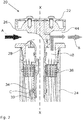
- FIG 3 shows in the first sectional schematic representation a housing head 22 according to the invention with a purge air switch 48.
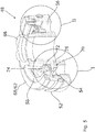
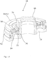
- the structure of the purge air switch 48 is in particular from the Figures 4 and 5 clear.
- the purge air switch 48 has a base body 50 which, in the exemplary embodiment shown, surrounds free ends of both the inner tube 28 and the core tube 30.
- the housing head 22 has a housing section 60 with an external thread 64, onto which the housing 24 can be screwed.
- the housing section 60 runs coaxially with the straight portion of the inner tube 28 which merges into the core tube 30.
- the base body 50 is sealed against the inner tube 28 and the core tube 30 via sealing rings 52.
- the base body 50 extends over the entire annular space 40 and has a pot-like basic shape.
- Through openings 56 are introduced into a bottom surface 54 of the base body 50, through which compressed air can be passed.
- a rolling membrane 58 is arranged, which also extends over the entire annular space 40.
- the rolling membrane 58 is held firmly on its side facing the housing section 60 via a tension ring 62.
- the base body 50 is arranged in the flow direction of the dry compressed air B immediately in front of the rolling membrane 58.
- the base body 50 surrounds the inner tube 28 with a valve ring guide 66.
- a valve ring 68 is held on this valve ring guide 66 and can be displaced along the longitudinal axis X-X, which runs along the core tube 30 and the straight portion of the inner tube 28.
- the valve ring 68 is formed from a lower valve part 70 and an upper valve part 72, between which the rolling membrane 58 is held (cf. Figure 4 ). This means that when the rolling membrane 58 moves along the longitudinal axis XX of the valve ring 68, it is also moved.
- the base body 50 also has a sealing ring 52 on its outside, which seals against the housing section 60.
- FIG. 5 illustrates that there are several overflow channels 74 in the valve ring guide 66 along the longitudinal axis XX in the exemplary embodiment shown, which are arranged uniformly distributed around the inner tube 28.
- the overflow channels 74 are formed by grooves, the depth of which increases in the direction of flow of the compressed air. This is particularly on the right in Figure 5 recognizable. The course within the grooves is therefore conical.
- Figure 5 shows the valve ring 68 in its initial position, in which it sits on the bottom surface 54 of the base body 50. In this position, the overflow channels 74 are closed, so that no dry compressed air can flow through them.
- Figure 5 also shows a purge air channel 76, which begins in the annular space 40 between the bottom surface 54 and the rolling membrane 58. Dry compressed air B is branched off through this purge air duct 76 and diverted in the direction of the hollow fibers 36. It can be seen that the purge air channel 76 is largely closed by the valve ring 68 in the starting position thereof.
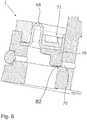
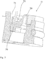
- valve ring 68 The starting position of the valve ring 68, the purge air duct 76 and an overflow duct 74 are shown in FIGS Figures 6 and 7 easier to see in an enlarged view.
- the rolling membrane 58 has an inflow side 78 and an outflow side 80, the inflow side 78 of the incoming dried compressed air or the housing 24 and the outflow side 80 facing the housing head 22 and the outlet 44.
- the valve ring 68 has a passage 82 in the area of the purge air channel 76, which passage is formed by a shoulder.
- This passage 82 or shoulder has the effect that even in the initial position of the valve ring 68, a small proportion of dry compressed air B as creeping air D can escape through the purge air duct 76.
- This creeping air D serves as a control air for the overall system.
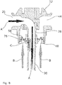
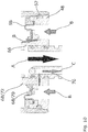
- FIGs 8 to 10 illustrate the flow of compressed air through the housing head 22 in the region of the purge air switch 48
- Figures 8 and 9 show the valve ring 68 in its initial position. It can be seen that compressed air hits the inflow side 78 of the rolling membrane 58. Since no compressed air is extracted, the valve ring 68 remains in its initial position and closes both the overflow channels 74 and the purge air channel 76.
- Figure 9 also clarifies that only a small proportion of compressed air is discharged through the passage 82 as creeping air D.
- the purge air channel 76 has a first section which runs essentially transversely to the longitudinal axis XX, a second section which runs parallel to the longitudinal axis XX and a third section which again runs transversely to the longitudinal axis XX.
- the purge air channel 76 thus redirects the purge air C and the creeping air D and directs them against the basic flow direction within the housing 24 back into the housing ring space 34 into the area between the holding elements 38 of the hollow fibers 36. There, the dry compressed air B flows outside between the hollow fibers 36 to the purge air outlet 46.
- a spring element 84 is indicated, which holds the valve ring 68 in its initial position. Only when the pressure generated by the compressed air exceeds the spring force of the spring element 68 does the valve ring 68 lift off from the bottom surface 54.
- Figures 10 and 11 show the valve ring 68 in the raised position, in which it does not rest on the bottom surface 54. It can be clearly seen that the purge air duct 76 and the overflow ducts 74 are released.
- Figure 10 illustrates the functioning of the deepening groove and the continuous widening of the overflow channels 74 in the direction of flow. The further the valve ring 68 is spaced from the bottom surface 54, the larger the diameter of the free opening for the compressed air.
- the invention is not limited to the exemplary embodiment shown, this merely represents a first embodiment variant of the invention.
- the overflow channels 74 can also be arranged in the valve ring 68. It is also conceivable that the valve ring 68 with the rolling membrane 58 lifts off in the outer region and is held immovably on the inner tube 28.
Landscapes
- Chemical & Material Sciences (AREA)
- Engineering & Computer Science (AREA)
- Analytical Chemistry (AREA)
- General Chemical & Material Sciences (AREA)
- Oil, Petroleum & Natural Gas (AREA)
- Chemical Kinetics & Catalysis (AREA)
- Drying Of Gases (AREA)
- Separation Using Semi-Permeable Membranes (AREA)
- Safety Valves (AREA)
Claims (9)
- Tête de boîtier (22) pour un dispositif de séchage pour air comprimé, qui peut être connectée à un boîtier (24) à l'intérieur duquel est agencé un filtre à membrane, de préférence un faisceau de membranes à fibres creuses, comprenanta) une entrée (26) pour de l'air comprimé humide (A) laquelle débouche dans un tube intérieur (28) qui est entouré, au moins par sections, de façon coaxiale par une portion de boîtier (60),b)une sortie (44) pour de l'air comprimé séché (B) laquelle débouche dans un espace annulaire (40) qui est réalisé entre une face extérieure dudit tube intérieur (28) et une face intérieure de ladite portion de boîtier (60),dans laquelle- un guide d'anneau de vanne (66) d'un corps de base (50) entoure le tube intérieur (28) et est maintenu de manière immobile sur celui-ci,- dans ledit espace annulaire (40) est disposée une membrane roulante annulaire (58) qui est maintenue sur sa face extérieure et est reliée sur sa face intérieure à un anneau de vanne (68) qui entoure ledit guide d'anneau de vanne (66) du corps de base (50) et est déplaçable le long d'un axe longitudinal (XX) du guide d'anneau de vanne (66),- entre ledit anneau de vanne (68) et ledit guide d'anneau de vanne (66) est disposé au moins un canal de trop-plein (74) qui passe devant la membrane roulante (58) dans le sens d'écoulement de l'air comprimé et est fermé par ledit anneau de vanne (68) dans sa position initiale dans laquelle il n'y a pour l'essentiel pas de demande en air comprimé,- ledit guide d'anneau de vanne (66) présente un canal d'air de rinçage (76) à travers lequel de l'air comprimé sec (B) peut être redirigé en direction du filtre à membrane et qui est pour l'essentiel fermé par l'anneau de vanne (68) dans sa position initiale.
- Tête de boîtier (22) selon la revendication 1, caractérisée par le fait que l'anneau de vanne (68) présente un passage au niveau de son appui sur le canal d'air de rinçage (76), à travers lequel de l'air rampant sec (D) est dirigé en permanence dans ledit canal d'air de rinçage (76).
- Tête de boîtier (22) selon la revendication 1 ou la revendication 2, caractérisée par le fait que le corps de base (50) s'étend dans le sens d'écoulement de l'air comprimé sec (B) immédiatement devant la membrane roulante sur tout l'espace annulaire (40) et présente une forme de base de type pot, des ouvertures de passage (56) étant pratiquées dans une surface de fond (54) du corps de base (50).
- Tête de boîtier (22) selon l'une quelconque des revendications 1 à 3, caractérisée par le fait que ledit au moins un canal de trop-plein (74) est formé par une rainure dans le guide d'anneau de vanne (66).
- Tête de boîtier (22) selon la revendication 4, caractérisée par le fait que la profondeur de la rainure augmente dans le sens d'écoulement de l'air comprimé sec (B).
- Tête de boîtier (22) selon l'une quelconque des revendications 1 à 5, caractérisée par le fait que plusieurs canaux de trop-plein (74) sont prévus qui sont disposés de manière à être uniformément répartis autour du tube intérieur (28) dans le guide d'anneau de vanne (66).
- Tête de boîtier (22) selon l'une quelconque des revendications 1 à 6, caractérisée par le fait que le canal d'air de rinçage (76) présente une première section qui s'étend pour l'essentiel transversalement à l'axe longitudinal (XX) du guide d'anneau de vanne (66), une deuxième section qui s'étend parallèlement à l'axe longitudinal (X-X) du guide d'anneau de vanne (66) ainsi qu'une troisième section qui s'étend lui aussi transversalement à l'axe longitudinal (XX) et se termine dans l'espace annulaire de boîtier (34) entre des éléments de maintien des fibres creuses (36).
- Tête de boîtier (22) selon l'une quelconque des revendications 1 à 7, caractérisée par le fait qu'un élément formant ressort (84) est prévu qui maintient ledit anneau de vanne (68) dans sa position de départ lorsqu'aucun air comprimé sec (B) n'est demandé.
- Tête de boîtier (22) selon la revendication 8, caractérisée par le fait que l'élément formant ressort (84) est formé par un ressort hélicoïdal qui est disposé entre l'anneau de vanne (68) et une surface d'appui à l'intérieur de la tête de boîtier (22).
Applications Claiming Priority (2)
| Application Number | Priority Date | Filing Date | Title |
|---|---|---|---|
| DE102014104386.3A DE102014104386B4 (de) | 2014-03-28 | 2014-03-28 | Gehäusekopf mit Spülluftregler |
| PCT/EP2014/078967 WO2015144270A1 (fr) | 2014-03-28 | 2014-12-22 | Tête de logement avec régulateur d'air de rinçage |
Publications (2)
| Publication Number | Publication Date |
|---|---|
| EP3122441A1 EP3122441A1 (fr) | 2017-02-01 |
| EP3122441B1 true EP3122441B1 (fr) | 2020-02-26 |
Family
ID=52432765
Family Applications (1)
| Application Number | Title | Priority Date | Filing Date |
|---|---|---|---|
| EP14830960.2A Active EP3122441B1 (fr) | 2014-03-28 | 2014-12-22 | Tête de logement avec régulateur d'air de rinçage |
Country Status (7)
| Country | Link |
|---|---|
| US (1) | US9895655B2 (fr) |
| EP (1) | EP3122441B1 (fr) |
| JP (1) | JP6255513B2 (fr) |
| KR (1) | KR20160137612A (fr) |
| CN (1) | CN106163638B (fr) |
| DE (1) | DE102014104386B4 (fr) |
| WO (1) | WO2015144270A1 (fr) |
Families Citing this family (11)
| Publication number | Priority date | Publication date | Assignee | Title |
|---|---|---|---|---|
| US12279610B2 (en) | 2011-03-15 | 2025-04-22 | Paragonix Technonogies, Inc. | System for hypothermic transport of samples |
| JP6780817B2 (ja) | 2016-11-08 | 2020-11-04 | Smc株式会社 | 除湿エレメント及びそれを有する除湿装置 |
| WO2018098016A1 (fr) * | 2016-11-22 | 2018-05-31 | MANN+HUMMEL Filtration Technology US LLC | Clapet |
| US20210400952A1 (en) | 2017-06-07 | 2021-12-30 | Paragonix Technologies, Inc. | Apparatus for tissue transport and preservation |
| DE102017116263A1 (de) | 2017-07-19 | 2019-01-24 | Beko Technologies Gmbh | Profilierte Drucklufttrockner-Hohlfasermembrane |
| US11446610B2 (en) * | 2019-04-03 | 2022-09-20 | Generon Igs, Inc. | Gas separation membrane module with enhanced performance |
| AU2020404941A1 (en) * | 2019-12-16 | 2022-06-16 | Schlumberger Technology B.V. | Membrane module |
| US11691108B1 (en) * | 2021-12-31 | 2023-07-04 | L'Air Liquide, Société Anonyme pour l'Etude et l'Exploitation des Procédés Georges Claude | Gas separation membrane module with hollow fiber carbon molecular sieve membranes |
| US20250064674A1 (en) | 2023-08-25 | 2025-02-27 | Paragonix Technologies, Inc. | Methods and systems for cyclically inflating and deflating a lung ex-vivo |
| US12410408B2 (en) | 2024-02-02 | 2025-09-09 | Paragonix Technologies, Inc. | Method for hypothermic transport of biological samples |
| USD1087382S1 (en) | 2025-01-30 | 2025-08-05 | Paragonix Technologies, Inc. | Device for transporting a biological sample |
Family Cites Families (25)
| Publication number | Priority date | Publication date | Assignee | Title |
|---|---|---|---|---|
| US5176725A (en) * | 1991-07-26 | 1993-01-05 | Air Products And Chemicals, Inc. | Multiple stage countercurrent hollow fiber membrane module |
| US5160514A (en) | 1991-12-12 | 1992-11-03 | Bend Research, Inc. | Sweep valve for dehydration valve |
| JPH0957043A (ja) * | 1995-08-29 | 1997-03-04 | Kuroda Precision Ind Ltd | エア除湿装置 |
| JPH1133338A (ja) * | 1997-07-16 | 1999-02-09 | Kuroda Precision Ind Ltd | 膜式ドライヤ |
| AT405971B (de) | 1997-09-10 | 2000-01-25 | Hygrama Ag | Membrantrockner für feuchte luft |
| US6128825A (en) * | 1997-12-12 | 2000-10-10 | Westinghouse Air Brake Company | Combination main reservoir and gas drying apparatus |
| DE19839057A1 (de) | 1998-08-28 | 2000-03-02 | Koch Berthold | Spülluft-Regler für eine Trockenvorrichtung für Druckluft |
| JP2001070739A (ja) * | 1999-09-03 | 2001-03-21 | Nabco Ltd | 圧縮空気の除湿器及び除湿装置とそれらの改装システム |
| JP2001205033A (ja) | 2000-01-31 | 2001-07-31 | Toshiba Plant Kensetsu Co Ltd | 気体の除湿装置および自力駆動弁ならびにそのヘッドキャップ |
| JP2001219026A (ja) * | 2000-02-09 | 2001-08-14 | Nabco Ltd | 除湿装置 |
| US6755894B2 (en) * | 2001-05-02 | 2004-06-29 | Praxair Technology, Inc. | Hollow fiber membrane gas separation cartridge and gas purification assembly |
| US6740140B2 (en) | 2001-09-07 | 2004-05-25 | Praxair Technology, Inc. | Hollow fiber membrane system assembly with an internal reflux system |
| JP2006021076A (ja) * | 2004-07-06 | 2006-01-26 | Orion Mach Co Ltd | 中空糸膜ドライヤ装置 |
| EP2024061A4 (fr) * | 2006-06-06 | 2010-09-01 | Porous Media Corp | Commande de balayage pour séchoirs à membrane |
| US8017016B2 (en) * | 2006-07-07 | 2011-09-13 | Sims Carl W | Method and apparatus for pervaporation control in chromatographic systems |
| US7678177B2 (en) * | 2006-09-12 | 2010-03-16 | New York Air Brake Corporation | Membrane air dryer and sweep valve |
| US7731784B2 (en) * | 2006-10-11 | 2010-06-08 | New York Air Brake Corporation | Membrane air dryer with sweep air control |
| KR101365067B1 (ko) * | 2007-01-31 | 2014-02-20 | 에스피엑스 플로우 테크놀로지 유에스에이, 인크. | 가스막 분리장치용 일체형 스위프 제어기 |
| US20080223212A1 (en) * | 2007-03-16 | 2008-09-18 | Crowder Robert O | Reducing moisture content of compressed air |
| US7651551B2 (en) * | 2007-04-17 | 2010-01-26 | New York Air Brake Corporation | Membrane air dryer with pre-charge volume |
| US8066801B2 (en) * | 2007-04-24 | 2011-11-29 | New York Air Brake Corporation | Sweep air system for membrane air dryer |
| US20090049983A1 (en) * | 2007-08-22 | 2009-02-26 | Flair Corporation, A Delaware Corporation | Energy management system for membrane separation device |
| US8852319B2 (en) * | 2010-09-13 | 2014-10-07 | Membrane Technology And Research, Inc. | Membrane loop process for separating carbon dioxide for use in gaseous form from flue gas |
| US8821614B1 (en) * | 2012-09-28 | 2014-09-02 | U.S. Department Of Energy | Constant pressure high throughput membrane permeation testing system |
| US9289717B2 (en) * | 2013-12-18 | 2016-03-22 | Carleton Life Support Systems Inc. | Air drying system for OBOGS |
-
2014
- 2014-03-28 DE DE102014104386.3A patent/DE102014104386B4/de not_active Expired - Fee Related
- 2014-12-22 WO PCT/EP2014/078967 patent/WO2015144270A1/fr not_active Ceased
- 2014-12-22 KR KR1020167029715A patent/KR20160137612A/ko not_active Withdrawn
- 2014-12-22 CN CN201480077632.6A patent/CN106163638B/zh active Active
- 2014-12-22 JP JP2016559613A patent/JP6255513B2/ja not_active Expired - Fee Related
- 2014-12-22 EP EP14830960.2A patent/EP3122441B1/fr active Active
- 2014-12-22 US US15/129,323 patent/US9895655B2/en not_active Expired - Fee Related
Non-Patent Citations (1)
| Title |
|---|
| None * |
Also Published As
| Publication number | Publication date |
|---|---|
| EP3122441A1 (fr) | 2017-02-01 |
| CN106163638A (zh) | 2016-11-23 |
| CN106163638B (zh) | 2018-10-26 |
| KR20160137612A (ko) | 2016-11-30 |
| DE102014104386B4 (de) | 2019-03-14 |
| JP2017518166A (ja) | 2017-07-06 |
| US9895655B2 (en) | 2018-02-20 |
| WO2015144270A1 (fr) | 2015-10-01 |
| DE102014104386A1 (de) | 2015-10-01 |
| JP6255513B2 (ja) | 2017-12-27 |
| US20170113181A1 (en) | 2017-04-27 |
Similar Documents
| Publication | Publication Date | Title |
|---|---|---|
| EP3122441B1 (fr) | Tête de logement avec régulateur d'air de rinçage | |
| DE602004007356T2 (de) | Ventil und verfahren zur bereitstellung eines fluidimpulses | |
| DE2645948A1 (de) | Rueckspuelbare filtereinrichtung | |
| DE3407878C1 (de) | Rueckschlagventil fuer die Stempel von Schreitausbaugestellen | |
| DE2511662B2 (de) | Bewässerungsvorrichtung | |
| DE102014017801B4 (de) | Druckbegrenzungsventil | |
| EP0831245B1 (fr) | Amortisseur de chocs industriel | |
| EP1851098B9 (fr) | Cylindre de frein a accumulateur a ressort et de service combine avec dispositif de respiration | |
| DE4407974C2 (de) | Automatisches Bypass-Ventil | |
| DE1901776C3 (de) | Vorrichtung zum selbsttätigen Entlüften von Hydraulikanlagen | |
| DE1425595B2 (de) | Einrichtung zur daempfung von druckstoessen mit einem nadelventil | |
| CH668628A5 (de) | Druckminderventil. | |
| DE69516941T2 (de) | Filtriereinheit für Fluide | |
| EP3209917B1 (fr) | Distributeur à commande assistée | |
| DE2914438C2 (de) | Vorrichtung zur automatischen Abschaltung einer beschädigten Zweigleitung in einem Pneumatik- oder Hydrauliksystem | |
| DE2813226C2 (de) | Absperr- und Regelventil | |
| DE2255192B2 (de) | Betätigungsvorrichtung für eine blockiergeschützte Fahrzeugbremsanlage | |
| EP0278333A2 (fr) | Dispositif de commande pour un séparateur de tuyau | |
| CH621401A5 (fr) | ||
| DE2759703C2 (fr) | ||
| DE102009048093B4 (de) | System- oder Rohrtrenner in Modulbauweise als Patrone | |
| WO1989005382A1 (fr) | Clapet de non-retour, notamment pour conduits d'eau potable | |
| DE2000106C3 (de) | Zumeßdüse | |
| DE10311754B4 (de) | Lackdruck-Steuereinrichtung | |
| DE1600712C3 (de) | Unterdruck-Entlastungsventil für Druckmittelsysteme |
Legal Events
| Date | Code | Title | Description |
|---|---|---|---|
| PUAI | Public reference made under article 153(3) epc to a published international application that has entered the european phase |
Free format text: ORIGINAL CODE: 0009012 |
|
| STAA | Information on the status of an ep patent application or granted ep patent |
Free format text: STATUS: REQUEST FOR EXAMINATION WAS MADE |
|
| 17P | Request for examination filed |
Effective date: 20160825 |
|
| AK | Designated contracting states |
Kind code of ref document: A1 Designated state(s): AL AT BE BG CH CY CZ DE DK EE ES FI FR GB GR HR HU IE IS IT LI LT LU LV MC MK MT NL NO PL PT RO RS SE SI SK SM TR |
|
| AX | Request for extension of the european patent |
Extension state: BA ME |
|
| DAX | Request for extension of the european patent (deleted) | ||
| GRAP | Despatch of communication of intention to grant a patent |
Free format text: ORIGINAL CODE: EPIDOSNIGR1 |
|
| STAA | Information on the status of an ep patent application or granted ep patent |
Free format text: STATUS: GRANT OF PATENT IS INTENDED |
|
| INTG | Intention to grant announced |
Effective date: 20190925 |
|
| GRAS | Grant fee paid |
Free format text: ORIGINAL CODE: EPIDOSNIGR3 |
|
| GRAA | (expected) grant |
Free format text: ORIGINAL CODE: 0009210 |
|
| STAA | Information on the status of an ep patent application or granted ep patent |
Free format text: STATUS: THE PATENT HAS BEEN GRANTED |
|
| AK | Designated contracting states |
Kind code of ref document: B1 Designated state(s): AL AT BE BG CH CY CZ DE DK EE ES FI FR GB GR HR HU IE IS IT LI LT LU LV MC MK MT NL NO PL PT RO RS SE SI SK SM TR |
|
| REG | Reference to a national code |
Ref country code: GB Ref legal event code: FG4D Free format text: NOT ENGLISH |
|
| REG | Reference to a national code |
Ref country code: CH Ref legal event code: EP |
|
| REG | Reference to a national code |
Ref country code: AT Ref legal event code: REF Ref document number: 1236958 Country of ref document: AT Kind code of ref document: T Effective date: 20200315 |
|
| REG | Reference to a national code |
Ref country code: IE Ref legal event code: FG4D Free format text: LANGUAGE OF EP DOCUMENT: GERMAN |
|
| REG | Reference to a national code |
Ref country code: DE Ref legal event code: R096 Ref document number: 502014013718 Country of ref document: DE |
|
| REG | Reference to a national code |
Ref country code: NL Ref legal event code: FP |
|
| PG25 | Lapsed in a contracting state [announced via postgrant information from national office to epo] |
Ref country code: RS Free format text: LAPSE BECAUSE OF FAILURE TO SUBMIT A TRANSLATION OF THE DESCRIPTION OR TO PAY THE FEE WITHIN THE PRESCRIBED TIME-LIMIT Effective date: 20200226 Ref country code: NO Free format text: LAPSE BECAUSE OF FAILURE TO SUBMIT A TRANSLATION OF THE DESCRIPTION OR TO PAY THE FEE WITHIN THE PRESCRIBED TIME-LIMIT Effective date: 20200526 Ref country code: FI Free format text: LAPSE BECAUSE OF FAILURE TO SUBMIT A TRANSLATION OF THE DESCRIPTION OR TO PAY THE FEE WITHIN THE PRESCRIBED TIME-LIMIT Effective date: 20200226 |
|
| REG | Reference to a national code |
Ref country code: LT Ref legal event code: MG4D |
|
| PG25 | Lapsed in a contracting state [announced via postgrant information from national office to epo] |
Ref country code: HR Free format text: LAPSE BECAUSE OF FAILURE TO SUBMIT A TRANSLATION OF THE DESCRIPTION OR TO PAY THE FEE WITHIN THE PRESCRIBED TIME-LIMIT Effective date: 20200226 Ref country code: IS Free format text: LAPSE BECAUSE OF FAILURE TO SUBMIT A TRANSLATION OF THE DESCRIPTION OR TO PAY THE FEE WITHIN THE PRESCRIBED TIME-LIMIT Effective date: 20200626 Ref country code: LV Free format text: LAPSE BECAUSE OF FAILURE TO SUBMIT A TRANSLATION OF THE DESCRIPTION OR TO PAY THE FEE WITHIN THE PRESCRIBED TIME-LIMIT Effective date: 20200226 Ref country code: SE Free format text: LAPSE BECAUSE OF FAILURE TO SUBMIT A TRANSLATION OF THE DESCRIPTION OR TO PAY THE FEE WITHIN THE PRESCRIBED TIME-LIMIT Effective date: 20200226 Ref country code: GR Free format text: LAPSE BECAUSE OF FAILURE TO SUBMIT A TRANSLATION OF THE DESCRIPTION OR TO PAY THE FEE WITHIN THE PRESCRIBED TIME-LIMIT Effective date: 20200527 Ref country code: BG Free format text: LAPSE BECAUSE OF FAILURE TO SUBMIT A TRANSLATION OF THE DESCRIPTION OR TO PAY THE FEE WITHIN THE PRESCRIBED TIME-LIMIT Effective date: 20200526 |
|
| PG25 | Lapsed in a contracting state [announced via postgrant information from national office to epo] |
Ref country code: SM Free format text: LAPSE BECAUSE OF FAILURE TO SUBMIT A TRANSLATION OF THE DESCRIPTION OR TO PAY THE FEE WITHIN THE PRESCRIBED TIME-LIMIT Effective date: 20200226 Ref country code: EE Free format text: LAPSE BECAUSE OF FAILURE TO SUBMIT A TRANSLATION OF THE DESCRIPTION OR TO PAY THE FEE WITHIN THE PRESCRIBED TIME-LIMIT Effective date: 20200226 Ref country code: SK Free format text: LAPSE BECAUSE OF FAILURE TO SUBMIT A TRANSLATION OF THE DESCRIPTION OR TO PAY THE FEE WITHIN THE PRESCRIBED TIME-LIMIT Effective date: 20200226 Ref country code: RO Free format text: LAPSE BECAUSE OF FAILURE TO SUBMIT A TRANSLATION OF THE DESCRIPTION OR TO PAY THE FEE WITHIN THE PRESCRIBED TIME-LIMIT Effective date: 20200226 Ref country code: CZ Free format text: LAPSE BECAUSE OF FAILURE TO SUBMIT A TRANSLATION OF THE DESCRIPTION OR TO PAY THE FEE WITHIN THE PRESCRIBED TIME-LIMIT Effective date: 20200226 Ref country code: LT Free format text: LAPSE BECAUSE OF FAILURE TO SUBMIT A TRANSLATION OF THE DESCRIPTION OR TO PAY THE FEE WITHIN THE PRESCRIBED TIME-LIMIT Effective date: 20200226 Ref country code: ES Free format text: LAPSE BECAUSE OF FAILURE TO SUBMIT A TRANSLATION OF THE DESCRIPTION OR TO PAY THE FEE WITHIN THE PRESCRIBED TIME-LIMIT Effective date: 20200226 Ref country code: PT Free format text: LAPSE BECAUSE OF FAILURE TO SUBMIT A TRANSLATION OF THE DESCRIPTION OR TO PAY THE FEE WITHIN THE PRESCRIBED TIME-LIMIT Effective date: 20200719 Ref country code: DK Free format text: LAPSE BECAUSE OF FAILURE TO SUBMIT A TRANSLATION OF THE DESCRIPTION OR TO PAY THE FEE WITHIN THE PRESCRIBED TIME-LIMIT Effective date: 20200226 |
|
| REG | Reference to a national code |
Ref country code: DE Ref legal event code: R097 Ref document number: 502014013718 Country of ref document: DE |
|
| PLBE | No opposition filed within time limit |
Free format text: ORIGINAL CODE: 0009261 |
|
| STAA | Information on the status of an ep patent application or granted ep patent |
Free format text: STATUS: NO OPPOSITION FILED WITHIN TIME LIMIT |
|
| 26N | No opposition filed |
Effective date: 20201127 |
|
| PG25 | Lapsed in a contracting state [announced via postgrant information from national office to epo] |
Ref country code: SI Free format text: LAPSE BECAUSE OF FAILURE TO SUBMIT A TRANSLATION OF THE DESCRIPTION OR TO PAY THE FEE WITHIN THE PRESCRIBED TIME-LIMIT Effective date: 20200226 Ref country code: PL Free format text: LAPSE BECAUSE OF FAILURE TO SUBMIT A TRANSLATION OF THE DESCRIPTION OR TO PAY THE FEE WITHIN THE PRESCRIBED TIME-LIMIT Effective date: 20200226 |
|
| REG | Reference to a national code |
Ref country code: CH Ref legal event code: PL |
|
| PG25 | Lapsed in a contracting state [announced via postgrant information from national office to epo] |
Ref country code: MC Free format text: LAPSE BECAUSE OF FAILURE TO SUBMIT A TRANSLATION OF THE DESCRIPTION OR TO PAY THE FEE WITHIN THE PRESCRIBED TIME-LIMIT Effective date: 20200226 |
|
| PG25 | Lapsed in a contracting state [announced via postgrant information from national office to epo] |
Ref country code: IE Free format text: LAPSE BECAUSE OF NON-PAYMENT OF DUE FEES Effective date: 20201222 Ref country code: LU Free format text: LAPSE BECAUSE OF NON-PAYMENT OF DUE FEES Effective date: 20201222 |
|
| PG25 | Lapsed in a contracting state [announced via postgrant information from national office to epo] |
Ref country code: LI Free format text: LAPSE BECAUSE OF NON-PAYMENT OF DUE FEES Effective date: 20201231 Ref country code: CH Free format text: LAPSE BECAUSE OF NON-PAYMENT OF DUE FEES Effective date: 20201231 |
|
| REG | Reference to a national code |
Ref country code: AT Ref legal event code: MM01 Ref document number: 1236958 Country of ref document: AT Kind code of ref document: T Effective date: 20201222 |
|
| PG25 | Lapsed in a contracting state [announced via postgrant information from national office to epo] |
Ref country code: AT Free format text: LAPSE BECAUSE OF NON-PAYMENT OF DUE FEES Effective date: 20201222 |
|
| PG25 | Lapsed in a contracting state [announced via postgrant information from national office to epo] |
Ref country code: TR Free format text: LAPSE BECAUSE OF FAILURE TO SUBMIT A TRANSLATION OF THE DESCRIPTION OR TO PAY THE FEE WITHIN THE PRESCRIBED TIME-LIMIT Effective date: 20200226 Ref country code: MT Free format text: LAPSE BECAUSE OF FAILURE TO SUBMIT A TRANSLATION OF THE DESCRIPTION OR TO PAY THE FEE WITHIN THE PRESCRIBED TIME-LIMIT Effective date: 20200226 Ref country code: CY Free format text: LAPSE BECAUSE OF FAILURE TO SUBMIT A TRANSLATION OF THE DESCRIPTION OR TO PAY THE FEE WITHIN THE PRESCRIBED TIME-LIMIT Effective date: 20200226 |
|
| PG25 | Lapsed in a contracting state [announced via postgrant information from national office to epo] |
Ref country code: MK Free format text: LAPSE BECAUSE OF FAILURE TO SUBMIT A TRANSLATION OF THE DESCRIPTION OR TO PAY THE FEE WITHIN THE PRESCRIBED TIME-LIMIT Effective date: 20200226 Ref country code: AL Free format text: LAPSE BECAUSE OF FAILURE TO SUBMIT A TRANSLATION OF THE DESCRIPTION OR TO PAY THE FEE WITHIN THE PRESCRIBED TIME-LIMIT Effective date: 20200226 |
|
| PGFP | Annual fee paid to national office [announced via postgrant information from national office to epo] |
Ref country code: DE Payment date: 20241216 Year of fee payment: 11 |
|
| PGFP | Annual fee paid to national office [announced via postgrant information from national office to epo] |
Ref country code: NL Payment date: 20241217 Year of fee payment: 11 Ref country code: BE Payment date: 20241216 Year of fee payment: 11 |
|
| PGFP | Annual fee paid to national office [announced via postgrant information from national office to epo] |
Ref country code: GB Payment date: 20241218 Year of fee payment: 11 |
|
| PGFP | Annual fee paid to national office [announced via postgrant information from national office to epo] |
Ref country code: FR Payment date: 20241219 Year of fee payment: 11 |
|
| PGFP | Annual fee paid to national office [announced via postgrant information from national office to epo] |
Ref country code: IT Payment date: 20241216 Year of fee payment: 11 |