EP3122565B1 - Dispositif de maintien de support et appareil d'enregistrement - Google Patents
Dispositif de maintien de support et appareil d'enregistrement Download PDFInfo
- Publication number
- EP3122565B1 EP3122565B1 EP15770280.4A EP15770280A EP3122565B1 EP 3122565 B1 EP3122565 B1 EP 3122565B1 EP 15770280 A EP15770280 A EP 15770280A EP 3122565 B1 EP3122565 B1 EP 3122565B1
- Authority
- EP
- European Patent Office
- Prior art keywords
- tray
- section
- holding
- recording medium
- frame
- Prior art date
- Legal status (The legal status is an assumption and is not a legal conclusion. Google has not performed a legal analysis and makes no representation as to the accuracy of the status listed.)
- Active
Links
- 230000002093 peripheral effect Effects 0.000 claims description 11
- 238000007639 printing Methods 0.000 description 11
- 230000032258 transport Effects 0.000 description 11
- 229910052751 metal Inorganic materials 0.000 description 5
- 239000002184 metal Substances 0.000 description 5
- 229910052782 aluminium Inorganic materials 0.000 description 4
- XAGFODPZIPBFFR-UHFFFAOYSA-N aluminium Chemical compound [Al] XAGFODPZIPBFFR-UHFFFAOYSA-N 0.000 description 4
- 239000000758 substrate Substances 0.000 description 4
- 230000037303 wrinkles Effects 0.000 description 4
- 238000001125 extrusion Methods 0.000 description 2
- 238000000034 method Methods 0.000 description 2
- 239000011347 resin Substances 0.000 description 2
- 229920005989 resin Polymers 0.000 description 2
- NIXOWILDQLNWCW-UHFFFAOYSA-N acrylic acid group Chemical group C(C=C)(=O)O NIXOWILDQLNWCW-UHFFFAOYSA-N 0.000 description 1
- 239000004744 fabric Substances 0.000 description 1
- 238000007641 inkjet printing Methods 0.000 description 1
- 239000000463 material Substances 0.000 description 1
- 239000007921 spray Substances 0.000 description 1
Images



Classifications
-
- B—PERFORMING OPERATIONS; TRANSPORTING
- B41—PRINTING; LINING MACHINES; TYPEWRITERS; STAMPS
- B41J—TYPEWRITERS; SELECTIVE PRINTING MECHANISMS, i.e. MECHANISMS PRINTING OTHERWISE THAN FROM A FORME; CORRECTION OF TYPOGRAPHICAL ERRORS
- B41J3/00—Typewriters or selective printing or marking mechanisms characterised by the purpose for which they are constructed
- B41J3/407—Typewriters or selective printing or marking mechanisms characterised by the purpose for which they are constructed for marking on special material
- B41J3/4078—Printing on textile
-
- B—PERFORMING OPERATIONS; TRANSPORTING
- B41—PRINTING; LINING MACHINES; TYPEWRITERS; STAMPS
- B41J—TYPEWRITERS; SELECTIVE PRINTING MECHANISMS, i.e. MECHANISMS PRINTING OTHERWISE THAN FROM A FORME; CORRECTION OF TYPOGRAPHICAL ERRORS
- B41J11/00—Devices or arrangements of selective printing mechanisms, e.g. ink-jet printers or thermal printers, for supporting or handling copy material in sheet or web form
- B41J11/58—Supply holders for sheets or fan-folded webs, e.g. shelves, tables, scrolls, pile holders
-
- B—PERFORMING OPERATIONS; TRANSPORTING
- B41—PRINTING; LINING MACHINES; TYPEWRITERS; STAMPS
- B41J—TYPEWRITERS; SELECTIVE PRINTING MECHANISMS, i.e. MECHANISMS PRINTING OTHERWISE THAN FROM A FORME; CORRECTION OF TYPOGRAPHICAL ERRORS
- B41J11/00—Devices or arrangements of selective printing mechanisms, e.g. ink-jet printers or thermal printers, for supporting or handling copy material in sheet or web form
- B41J11/02—Platens
-
- B—PERFORMING OPERATIONS; TRANSPORTING
- B41—PRINTING; LINING MACHINES; TYPEWRITERS; STAMPS
- B41J—TYPEWRITERS; SELECTIVE PRINTING MECHANISMS, i.e. MECHANISMS PRINTING OTHERWISE THAN FROM A FORME; CORRECTION OF TYPOGRAPHICAL ERRORS
- B41J11/00—Devices or arrangements of selective printing mechanisms, e.g. ink-jet printers or thermal printers, for supporting or handling copy material in sheet or web form
- B41J11/02—Platens
- B41J11/06—Flat page-size platens or smaller flat platens having a greater size than line-size platens
-
- B—PERFORMING OPERATIONS; TRANSPORTING
- B41—PRINTING; LINING MACHINES; TYPEWRITERS; STAMPS
- B41J—TYPEWRITERS; SELECTIVE PRINTING MECHANISMS, i.e. MECHANISMS PRINTING OTHERWISE THAN FROM A FORME; CORRECTION OF TYPOGRAPHICAL ERRORS
- B41J13/00—Devices or arrangements of selective printing mechanisms, e.g. ink-jet printers or thermal printers, specially adapted for supporting or handling copy material in short lengths, e.g. sheets
- B41J13/10—Sheet holders, retainers, movable guides, or stationary guides
-
- B—PERFORMING OPERATIONS; TRANSPORTING
- B41—PRINTING; LINING MACHINES; TYPEWRITERS; STAMPS
- B41J—TYPEWRITERS; SELECTIVE PRINTING MECHANISMS, i.e. MECHANISMS PRINTING OTHERWISE THAN FROM A FORME; CORRECTION OF TYPOGRAPHICAL ERRORS
- B41J13/00—Devices or arrangements of selective printing mechanisms, e.g. ink-jet printers or thermal printers, specially adapted for supporting or handling copy material in short lengths, e.g. sheets
- B41J13/10—Sheet holders, retainers, movable guides, or stationary guides
- B41J13/103—Sheet holders, retainers, movable guides, or stationary guides for the sheet feeding section
Definitions
- the present invention relates to a recording medium holding device that holds a recording medium on which an image is recorded and a recording apparatus.
- a platen device mounted on an ink jet printer for recording an image on a medium to be printed such as T-shirts
- a platen device which includes a platen on which the medium to be printed is mounted, a support plate that is disposed below the platen, a frame that pinches and holds the medium to be printed mounted on the platen together with the support plate, and a platen tray that is positioned below these members and houses a portion not mounted on the platen of the medium to be printed pinched by the frame so as to receive the portion.
- the platen device has a configuration in which the platen, the support plate, the frame, and the platen tray described above are integrally assembled with a bottom portion (see PTL 1).
- US 2003/197772 discloses a platen device for holding a workpiece in an ink-jet printer operable to perform a printing operation on a printing surface of the workpiece.
- the platen device is movable into a printing area in which a printing head is operated to deliver an ink onto said printing surface for thereby forming an image on said printing surface.
- the platen device includes a platen arranged to permit the workpiece to be placed on the platen such that a printing portion of the workpiece having the printing surface is in direct contact with a surface of the platen.
- a space-defining structure partially defining an accommodating space is provided below the platen to accommodate non-printing portions of the workpiece which extend from the printing portion outwardly of the platen.
- US 6,622,953 discloses a roll holder device for use with a recording paper roll including a tubular spool shaft and continuous recording paper wound about the tubular spool shaft in a roll form.
- first and second holder cores are inserted in respectively first and second ends of the tubular spool shaft.
- a holder frame supports the first and second holder cores in a rotatable manner.
- Anti-dropping levers prevent the tubular spool shaft from dropping from the first and second holder cores by pushing a shaft inner surface of the tubular spool shaft.
- US 2005/068400 discloses an inkjet printing device, which is provided with a holding unit that is used to hold a substrate to be subjected to a printing operation, and an inkjet head that ejects ink onto the substrate held by the holding unit.
- the holding unit is movable between a first posture which allows the inkjet head to eject the ink onto the substrate held by the holding unit and a second posture in which the substrate is loaded onto the holding unit.
- a plurality of sizes of platens are prepared so as to correspond to media to be printed of various sizes and a user exchanges the platen according to the size of the medium to be printed.
- the platen device of the related art since the platen forms an integral structure with the frame, the platen is exchanged together with the frame and the like and if the size of the platen is large, the integral structure combined with the frame and the like is very heavy. Thus, exchange work of the platen is not easy.
- a recording medium holding device is defined in claim 1.
- a user can mount a first set tray on the tray mounting section and hold the recording medium between the first set tray and the holding frame. Furthermore, the user can mount a second set tray on the tray mounting section and hold the recording medium between the second set tray and the attachment by mounting the attachment on the holding frame.
- the user can hold and release the recording medium by the holding frame by performing a simple operation in which the holding frame is rotated between the holding position and the non-holding position.
- the holding frame is rotated between the holding position and the non-holding position.
- the recording medium holding device further includes a frame-side lock section that is provided in the holding frame and includes the hook member, and a base-side lock section that is provided in the base section and engages with the frame-side lock section of the holding frame positioned in the holding position.
- the holding frame is locked in the holding position by engaging the frame-side lock section with the base-side lock section. Then, since the same holding frame is shared for the first tray and the second tray, it is possible to reduce the number of frame-side lock sections without it being necessary to prepare a frame-side lock section for each holding frame as in a case where the holding frames are separately used for the first tray and the second tray.
- the recording medium holding device further includes a brake assist section that is mounted on the holding frame and brakes rotation of the holding frame to the holding position and assists rotation of the holding frame to the non-holding position.
- the brake assist section is configured of an assist hinge rotatably connecting the holding frame to the base section.
- the first tray has a tray body in which one surface of front and rear surfaces is the medium mounting surface, and a guide section that is provided in an edge portion of a surface opposite to the medium mounting surface of the tray body and guides an end portion of the recording medium hanging from between the tray body and the holding frame to the outside with respect to the tray body.
- the end portion of the recording medium hanging from between the tray body of the first tray and the holding frame is guided to the outside with respect to the tray body by the guide section, it is possible to increase a contact area between the tray body, the holding frame, and the recording medium.
- the recording medium is held between the first tray and the holding frame, it is easy to extend wrinkles of the held recording medium and it is possible to prevent the recording medium from being moved after the recording medium is held.
- the attachment has a plate section provided with an opening, and an attachment frame section that is provided along an edge portion of the opening in one surface of the front and rear surfaces of the plate section.
- the second tray has a tray body in which one surface of the front and rear surfaces is the medium mounting surface, and a guide section that is provided in the edge portion of the surface opposite to the medium mounting surface of the tray body and guides the end portion of the recording medium hanging from between the tray body and the attachment frame section to the outside with respect to the tray body.
- the holding frame has a frame body in which an engaging section engaging with an outer peripheral edge of the attachment is provided in an inner peripheral edge thereof, and a locking member that is movably provided in the frame body between a locked position in which the attachment engaged with the engaging section is locked to the frame body and an unlocked position in which the locking of the attachment is released.
- the user can mount the attachment on the holding frame and separate the attachment from the holding frame by performing a simple operation in which the locking member is moved between the locked position and the unlocked position.
- a recording apparatus includes the recording medium holding device described above and a recording section that records an image to the recording medium held by the recording medium holding device.
- the recording section is not particularly limited and, for example, a recording section ejecting ink using an ink jet type recording section can be used.
- the recording apparatus records an image on a recording medium such as T-shirts held in a medium holding section by ejecting ink using an ink jet type recording section.
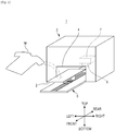
- a recording apparatus 1 includes a medium holding section 2 that holds a recording medium M, a substantially rectangular-shaped recording section 3 that is laterally long, and a transport section 5 that transports the medium holding section 2 forward and backward.
- the recording section 3 records the image on the recording medium M held in the medium holding section 2.
- the recording section 3 includes a carriage 7 on which an ink jet head 6 is mounted, and a head moving mechanism (not illustrated) that moves the ink jet head 6 right and left via the carriage 7.
- the head moving mechanism is configured of a belt mechanism driven by a motor.
- the transport section 5 moves the medium holding section 2 between a set position on a front side and a recording start position on a rear side through an entrance 4 provided on the front side of the recording section 3.
- the transport section 5 is configured of a belt mechanism driven by a motor.
- the recording apparatus 1 When recording the image on the recording medium M by the recording apparatus 1, first, the user sets the recording medium M in the medium holding section 2 that is moved in the set position. Then, when the recording apparatus 1 receives an instruction of start of recording, the transport section 5 moves the medium holding section 2 from the set position to the recording start position through the entrance 4. Thereafter, the transport section 5 intermittently moves the medium holding section 2 from the recording start position to the front side and the ink jet head 6 faces the recording medium M set in the medium holding section 2, which passes and ejects the ink while reciprocating to the right and left. Thus, the recording apparatus 1 performs a recording operation by which the image is recorded on the recording medium M.
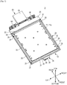
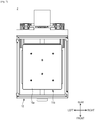
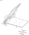
- the medium holding section 2 has a tray 11 on which the recording medium M is set, a holding frame 12 that holds the recording medium M together with the tray 11, a tray mounting section 13 on which the tray 11 is mounted on an upper surface thereof, and a base section 14 that supports the tray mounting section 13.
- the tray 11 is detachably mounted on the tray mounting section 13 and is configured separately from the holding frame 12 and the like.
- a large tray 11a is used for holding a recording medium M of a relatively large size
- the intermediate tray 11b is used for holding a recording medium M of an intermediate size
- the small tray 11c is used for holding the recording medium M of a relatively small size.
- each tray body 16 of the large tray 11a, the intermediate tray 11b, and the small tray 11c are respectively 50 cm x 71 cm (20 x 28 inches), 41 cm x 50 cm (16 x 20 inches), and 36 cm x 41 cm (14 x 16 inches).
- the large tray 11a is an example of a "first tray”
- the intermediate tray 11b or the small tray 11c being an example of a "second tray”.
- the medium holding section 2 includes an attachment mounted on the holding frame 12.
- a first attachment 15b that is mounted on the holding frame 12 if the intermediate tray 11b is mounted on the tray mounting section 13, and a second attachment 15c that is mounted on the holding frame 12 if the small tray 11c is mounted on the tray mounting section 13 are provided in the attachment 15.
- the tray 11 includes the tray body 16, two guide sections 17 that are provided in right and left edge portions of a surface opposite to a medium mounting surface 16a (described below) of the tray body 16, that is, a lower surface, four tray concave sections 18 (see Figs. 6A to 6C ) that are provided by being dispersed in a rectangular shape at four positions on the lower surface of the tray body 16, and two front and rear positioning pins 19 (see Figs. 6A to 6C ) that are provided at substantially right and left center portions of the lower surface of the tray body 16.
- the tray body 16 is configured in a substantially rectangular plate with rounded edges.
- the upper surface of the tray body 16 is the medium mounting surface 16a on which the recording medium M is mounted.
- the recording medium M if tops such as T-shirts are used, both a front body and a rear body of the tops may be overlappingly mounted on the medium mounting surface 16a or one of the front body and the rear body may be mounted on the medium mounting surface 16a by wrapping upper and lower portions of the tray 11 by the front body and the rear body.
- the tray body 16 may be made of resin such as an acrylic plate and, for example, it is preferable that the tray body 16 is configured of an aluminum plate to ensure rigidity. Thus, when setting the recording medium M on the tray 11, the tray body 16 is prevented from being bent and it is possible to appropriately maintain a gap between the recording medium M mounted on the medium mounting surface 16a and the ink jet head 6.
- the guide section 17 is configured of a metal fitting of a substantially crank shape (see Figs. 6A to 6C ) in a cross-sectional view and includes a connection section 21 that comes into contact with the lower surface of the tray body 16, an outer hanging section 22 that is continuous downward from the outside of the connection section 21, a medium receiving section 23 that is continuous from the lower end of the outer hanging section 22 to the outside, and an inner hanging section 20 that is continuous downward from the inside of the connection section 21.
- the guide sections 17 are provided in the right and left edge portions of the lower surface of the tray body 16, but may be further provided in front and rear edge portions thereof.
- the two positioning pins 19 are configured to be longer than the four tray concave sections 18 and are inserted into two positioning holes (not illustrated) provided in the tray mounting section 13 from above until the four tray concave sections 18 abut the upper surface of the tray mounting section 13. Lengths of the four tray concave sections 18 are substantially equal to each other.
- the tray 11 faces the tray mounting section 13 and is supported at four points of the four tray concave sections 18.
- the holding frame 12 is connected to the base section 14 through an assist hinge 43 or a hinge metal fitting 44 (described below) provided in a rear end portion.
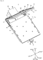
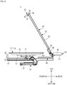
- the holding frame 12 is configured to rotate around an axis of the assist hinge 43 or the hinge metal fitting 44 between a holding position (see Fig. 2 ) that is a substantially horizontal posture and holds the recording medium M with the tray 11 and a non-holding position (see Figs. 3 and 4 ) that is an inclined posture and releases the holding of the recording medium M.
- the holding frame 12 includes a rectangular frame-shaped frame body 24, four locking members 25 that are provided in the vicinity of four corners of the frame body 24, and a hinge mounting section 26 which is provided in a rear portion of the frame body 24 and on which the assist hinge 43 or the hinge metal fitting 44 is mounted.
- the frame body 24 is configured by combining an aluminum extruded profile material having a cross section of a substantially inverted trapezoid rectangular shape in a rectangular shape.
- the frame body 24 includes a front frame member 31, a rear frame member 32, a left frame member 33, and a right frame member 34.
- An engaging step section 35 engaging with an outer peripheral edge of a plate section 54 (described below) of the attachment 15 is provided in an inside of each upper surface of the front frame member 31, the rear frame member 32, the left frame member 33, and the right frame member 34, that is, in an inner peripheral edge of the upper surface of the frame body 24.
- a frame-side lock section 36 is mounted on a substantially intermediate portion of the front of the front frame member 31.
- the hinge mounting section 26 is connected to a rear surface of the rear frame member 32.
- the locking members 25 are respectively mounted on both front and rear end portions of the left frame member 33 and the right frame member 34 by a rotation pin 37.
- the "engaging section” is configured of the engaging step section 35, but is not limited to this configuration, and, for example, the “engaging section” may be a groove formed on an inner surface of the left frame member 33 and the right frame member 34.
- a frame-side lock section 36 includes a hook support section 38 that is fixed to the front frame member 31 and a hook member 39 that is rotatably supported by the hook support section 38.
- the hook member 39 includes a hook section 41 that engages with a base-side lock section 53 described below and a knob section 42 for rotatably operating the hook member 39.
- the hook member 39 is configured to rotate between a hooked position in which the hook member 39 engages with the base-side lock section 53 and an unhooked position in which engagement of the hook member 39 with the base-side lock section 53 is released, and is biased to rotate to the hooked position by a spring (not illustrated).
- the user operates the hook member 39 of the frame-side lock section 36 such that it rotates to the unhooked position and releases the engagement of the frame-side lock section 36 with the base-side lock section 53 when operating the holding frame 12 to rotate to the non-holding position.
- the four locking members 25 are provided for locking the plate section 54 of the attachment 15 to the frame body 24.
- Each of the locking members 25 is configured to rotate around the rotation pin 37 between the locked position (see Figs. 5A to 5E ) in which the plate section 54 that is closed on the inside is locked to the frame body 24 and the unlocked position in which the engagement with the plate section 54 that is opened on the outside is released.
- the user rotates the locking member 25 to the locked position and locks the attachment 15 to the frame body 24 after dropping the attachment 15 to the engaging step section 35 of the frame body 24 in a state where the locking member 25 is positioned in the unlocked position. It is possible to mount the attachment 15 on the holding frame 12 and to separate the attachment 15 from the holding frame 12 by performing a simple operation of rotating the locking member 25 between the locked position and the unlocked position.
- the hinge mounting section 26 has a rectangular shape that is laterally long in a top view and has a length in the right-left direction substantially the same as those of the rear frame member 32.
- the assist hinge 43 is mounted on a substantially intermediate portion of the lower surface of the hinge mounting section 26.
- the hinge metal fittings 44 are respectively mounted closer to the left side and closer to the right side of the upper surface of the hinge mounting section 26.
- the assist hinge 43 includes a substantially flat rectangular parallelepiped fixing section 45 and a movable section 46 rotatably connected to the fixing section 45.
- the fixing section 45 is fixed to a hinge support section 51 (described below) of the base section 14, and the movable section 46 is fixed to the hinge mounting section 26.
- the fixing section 45 and the movable section 46 respectively have covers made of resin.
- a spring for assisting rotation of the holding frame 12 to the non-holding position and a damper for braking the rotation of the holding frame 12 to the holding position are built into the assist hinge 43. Since the rotation of the holding frame 12 to the non-holding position is assisted by the assist hinge 43, the user can easily perform a rotating operation of the holding frame 12 to the non-holding position. Furthermore, since the rotation of the holding frame 12 to the holding position is braked by the assist hinge 43, the user can completely perform the rotating operation of the holding frame 12 to the holding position without fingers being pinched between the holding frame 12 and the large tray 11a.
- the tray mounting section 13 has a substantially flat rectangular parallelepiped box shape and on which trays 11 of three sizes described above are selectively mounted on the upper surface.
- Two front and rear positioning holes are formed to pass through a substantially right and left intermediate portion of the tray mounting section 13.
- the two positioning pins 19 described above pass through the two positioning holes and thereby the tray 11 is mounted in a state of being positioned with respect to the tray mounting section 13.
- a tilt adjustment mechanism (not illustrated) for adjusting a tilt of the upper surface of the tray mounting section 13 is built into the tray mounting section 13. It is possible to adjust the tilt of the medium mounting surface 16a of the tray 11 mounted on the upper surface of the tray mounting section 13 by adjusting the tilt of the upper surface of the tray mounting section 13 by the tilt adjustment mechanism.
- it is possible to adjust the gap between a nozzle surface of the ink jet head 6 and the medium mounting surface 16a to be substantially uniform in an entire region of the medium mounting surface 16a.
- the base section 14 includes a substantially prism-shaped base body 47 extending longitudinally, a base concave section 48 protruding upward from a front end portion of the base body 47, a frame section 49 provided on a rearward upper surface of the base body 47 and configured by combining aluminum extrusion members, the plate-shaped hinge support section 51 connected to the rear from a substantially rear intermediate portion of the frame section 49, and a base leg 52 connected to downward from a rearward portion of the base body 47.
- the tray mounting section 13 described above is fixed to the upper portion of the base body 47.
- the base-side lock section 53 having a substantially inverted "L" shape in a side view is fixed to the upper portion of the front surface of the base concave section 48.
- the base-side lock section 53 engages with the frame-side lock section 36 provided in the holding frame 12 positioned in the holding position.
- the fixing section 45 of the assist hinge 43 described above is fixed to the upper surface of the hinge support section 51.
- the base leg 52 is mounted on the transport section 5 described above through a height adjustment mechanism (not illustrated).
- the attachment 15 includes the substantially rectangular plate-shaped plate section 54 that is thinner than the tray body 16 and an attachment frame section 55 that is provided on the lower surface of the plate section 54.
- the outer peripheral edge of the plate section 54 engages with the engaging step section 35 of the frame body 24 described above.
- a substantially rectangular-shaped attachment opening 56 is formed in the center portion of the plate section 54.
- a gap sufficient to pinch the recording medium M exists in the attachment opening 56 of the first attachment 15b and thereby the tray body 16 of the intermediate tray 11b enters the gap.
- a gap sufficient to pinch the recording medium M exists in the attachment opening 56 of the second attachment 15c and thereby the tray body 16 of the small tray 11c enters the gap.
- the attachment 15 is provided with the attachment frame section 55 along an edge portion of the attachment opening 56.
- the attachment frame section 55 is configured by combining the aluminum extrusion members having cross sections of substantially rectangular shapes in rectangular shapes.
- the user operates the holding frame 12 such that it rotates to non-holding position. Then, the user mounts the intermediate tray 11b on the tray mounting section 13. Then, the user mounts the recording medium M on the medium mounting surface 16a of the intermediate tray 11b. Furthermore, the user mounts the first attachment 15b on the holding frame 12.
- the user operates the holding frame 12 on which the first attachment 15b is mounted such that it rotates from the non-holding position to the holding position.
- the recording medium M is held between the edge portion of the attachment opening 56 of the first attachment 15b and the outer peripheral edge of the intermediate tray 11b.
- the frame-side lock section 36 engages with the base-side lock section 53 and the holding frame 12 is locked in the holding position.
- the user instructs starting of the recording with the recording apparatus 1.
- the user After the recording is performed on the recording medium M, the user operates the holding frame 12 such that it rotates from the holding position to the non-holding position. Then, the user removes the recording medium M on which the image is recorded from the medium holding section 2.
- the intermediate tray 11b and the large tray 11a are exchanged. That is, the intermediate tray 11b is removed from the tray mounting section 13 and, instead, the large tray 11a is mounted on the tray mounting section 13. Then, the user mounts the recording medium M on the medium mounting surface 16a of the large tray 11a.
- the user separates the first attachment 15b from the holding frame 12.
- the user operates the holding frame 12 that is separated from the first attachment 15b such that it rotates from the non-holding position to the holding position.
- the recording medium M is held between the inner peripheral edge of the holding frame 12 and the outer peripheral edge of the large tray 11a.
- the user instructs starting of the recording with the recording apparatus 1.
- the user After the recording is performed on the recording medium M, the user operates the holding frame 12 such that it rotates from the holding position to the non-holding position. Then, the user removes the recording medium M on which the image is recorded from the medium holding section 2.
- the user exchanges the large tray 11a and the small tray 11c. That is, the large tray 11a is removed from the tray mounting section 13 and, instead, the small tray 11c is mounted on the tray mounting section 13. Then, the user mounts the recording medium M on the medium mounting surface 16a of the small tray 11c. Furthermore, the user mounts the second attachment 15c on the holding frame 12.
- the user operates the holding frame 12 that is mounted on the second attachment 15c such that it rotates from the non-holding position to the holding position.
- the recording medium M is held between the edge portion of the attachment opening 56 of the second attachment 15c and the outer peripheral edge of the small tray 11c.
- the user instructs starting of the recording with the recording apparatus 1.
- the user After the recording is performed on the recording medium M, the user operates the holding frame 12 such that it rotates from the holding position to the non-holding position. Then, the user removes the recording medium M on which the image is recorded from the medium holding section 2.
- the order of the procedure is not limited to the embodiment and phases may be mixed in a range in which there is no interference with the work.
- the user can perform mutual exchange of the large tray 11a, the intermediate tray 11b, and the small tray 11c as a single body of the tray 11.
- the user can easily perform the exchange work of the tray 11.
- the user can hold the recording medium M between the large tray 11a and the holding frame 12 by mounting the large tray 11a on the tray mounting section 13 and separating the attachment 15 from the holding frame 12.
- the user can hold the recording medium M between the intermediate tray 11b and the first attachment 15b by mounting the intermediate tray 11b on the tray mounting section 13 and mounting the first attachment 15b on the holding frame 12.
- the user can hold the recording medium M between the small tray 11c and the second attachment 15c by mounting the small tray 11c on the tray mounting section 13 and mounting the second attachment 15c on the holding frame 12.
- the user may appropriately apply a processing solution to increase fixability of the ink to the recording medium M held in the medium holding section 2 using a spray and the like before the instruction is made to start the recording after the recording medium M is set on the medium holding section 2.
- a processing solution to increase fixability of the ink to the recording medium M held in the medium holding section 2 using a spray and the like before the instruction is made to start the recording after the recording medium M is set on the medium holding section 2.
- the same holding frame 12 is shared for the large tray 11a, the intermediate tray 11b, and the small tray 11c, it is possible to reduce the number of frame-side lock sections 36 or the assist hinges 43 without it being necessary to provide a frame-side lock section 36 or an assist hinge 43 for each holding frame 12 as in a case where separate holding frames 12 are used for the large tray 11a, the intermediate tray 11b, and the small tray 11c.
- the guide sections 17 of the large tray 11a guide the end portions of the recording medium M on the outside of the tray body 16 when the recording medium M is held between the large tray 11a and the holding frame 12 and thereby the end portions of the recording medium M hanging from between the tray body 16 of the large tray 11a and the frame body 24 of the holding frame 12 become substantially "L" shaped due to the medium receiving section 23 (see Fig. 6A ).
- the medium receiving section 23 see Fig. 6A
- wrinkles of the held recording medium M are extended and it is possible to prevent the recording medium M from moving after the recording medium M is held.
- the gap is provided between the outer hanging section 22 of the guide section 17 and the frame body 24, it is possible to release the held recording medium M being tensioned by the pin.
- the guide sections 17 of the intermediate tray 11b guide the end portions of the recording medium M on the outside of the tray body 16 when the recording medium M is held between the intermediate tray 11b and the first attachment 15b and thereby the end portions of the recording medium M hanging from between the tray body 16 of the intermediate tray 11b and the attachment frame section 55 of the first attachment 15b become substantially "L" shaped due to the medium receiving section 23 (see Fig. 6B ).
- the same configuration is applied to the guide section 17 of the small tray 11c (see Fig. 6C ).
- the recording medium M is held between the intermediate tray 11b and the first attachment 15b or the recording medium M is held between the small tray 11c and the second attachment 15c, it is possible to create a similar situation to the case where the recording medium M is held between the large tray 11a and the holding frame 12.
- the recording medium M is held between the intermediate tray 11b and the first attachment 15b, or the recording medium M is held between the small tray 11c and the second attachment 15c, the held recording medium M or the wrinkles of the held recording medium M are extended and it is possible to prevent the recording medium M from moving after the recording medium M is held.
- the guide section 17 of the intermediate tray 11b or the small tray 11c since the gap is provided between the outer hanging section 22 and the attachment frame section 55, it is possible to release the held recording medium M to be tensioned with the pin.
- the recording medium M may not be pinched between the large tray 11a and the holding frame 12, between the intermediate tray 11b and the first attachment 15b, or between the small tray 11c and the second attachment 15c.
- the intermediate tray 11b is mounted on the tray mounting section 13, the attachment 15 is separated from the holding frame 12, and end portions of the thick recording medium M hanging from the medium mounting surface 16a of the intermediate tray 11b enter between the intermediate tray 11b and the holding frame 12.
- the small tray 11c is mounted on the tray mounting section 13
- the first attachment 15b is mounted on the holding frame 12
- the end portions of the thick recording medium M hanging from the medium mounting surface 16a of the small tray 11c may enter between the small tray 11c and the first attachment 15b.
- the thick recording medium M it is possible to set the thick recording medium M on the medium holding section 2.
- the recording medium M can be fitted to the inside of the holding frame 12, it is possible to prevent the end portions of the recording medium M from being caught in the transport path by the transport section 5 in the recording operation.
- the medium holding section 2 of the modified example is substantially the same configuration as the medium holding section 2 described above, but is different from the medium holding section 2 described above in that gas springs 61 are provided instead of the assist hinge 43. Moreover, the description regarding the medium holding section 2 described above applies equally to the medium holding section 2 of the modified example unless otherwise specified.
- the medium holding section 2 of the modified example includes two gas springs 61 on both right and left sides of a holding frame 12.
- Frame-side connection sections 62 to which one end of each gas spring 61 is connected are formed in rearward portions of a left frame member 33 and a right frame member 34 of the holding frame 12.
- a frame support section 63 is provided in a rear end portion of a base section 14 instead of the frame section 49 and the hinge support section 51 described above.
- Hinge sections 64 that rotatably support the holding frame 12 are provided in right and left rear end portions of the frame support section 63.
- Base-side connection sections 65 to which the other end of the gas springs 61 are connected protrude from right and left front end portions of the frame support section 63.
- two gas springs 61 provided as described above assist rotation of the holding frame 12 to a non-holding position and brake rotation of the holding frame 12 to a holding position.
- the medium holding section 2 of the embodiment includes the assist hinge 43 or the gas spring 61, and thereby it is possible to improve operability when rotating the holding frame 12 between the holding position and the non-holding position. Furthermore, in a case where the assist hinge 43 is used, it is possible to mount the assist hinge 43 closer to a rotation shaft of the holding frame 12 than in a case where the gas spring 61 is used.
- the assist hinge 43 is not provided in both end portions of the holding frame 12 in a direction of the rotation shaft, that is, in the right and left both end portions, but is provided in a substantially intermediate portion of the holding frame 12 in the direction of the rotation shaft, that is, a substantially right and left intermediate portion as the embodiment, for a rotation base end portion of the holding frame 12 on which the assist hinge 43 is mounted, that is, the hinge mounting section 26, it is possible to reduce dimensions in a direction perpendicular to the direction of the rotation shaft, that is, in the forward and rearward direction and it is possible to reduce the size of the holding frame 12.
- assist hinge 43 and the gas spring 61 are an example of the "brake assist section".
- the recording medium M is not particularly limited, but, for example, a fabric can be appropriately used and clothes such as T-shirts can particularly preferably used.
- the medium holding section 2 may be used in a transport apparatus that transports the medium in addition to the recording apparatus and the medium holding section 2 may be used as a medium holding device for use in a cutting plotter.
Landscapes
- Engineering & Computer Science (AREA)
- Textile Engineering (AREA)
- Pile Receivers (AREA)
- Ink Jet (AREA)
- Handling Of Sheets (AREA)
- Handling Of Cut Paper (AREA)
- Sheets, Magazines, And Separation Thereof (AREA)
Claims (8)
- Dispositif de maintien de support d'enregistrement (2) comprenant :une section de montage de plateau (13) sur laquelle un premier plateau (11a) et un deuxième plateau (11c) sont adaptés pour y être sélectivement montés, le premier plateau ayant une surface de montage de support (16a) et le deuxième plateau ayant une surface de montage de support plus petite que celle du premier plateau ;une section de base (14) qui supporte la section de montage de plateau ;un cadre de maintien (12) qui est configuré séparément du premier plateau et du deuxième plateau et est adapté pour maintenir un support d'enregistrement (M) monté sur la surface de montage de support du premier plateau avec le premier plateau si le premier plateau est monté sur la section de montage de plateau ; etune fixation (15b) qui est montée sur un intérieur du cadre de maintien et est adaptée pour maintenir le support d'enregistrement monté sur la surface de montage de support du deuxième plateau avec le deuxième plateau si le deuxième plateau est monté sur la section de montage de plateau, dans lequelle cadre de maintien est relié à la section de base via une articulation (43) de sorte que le cadre de maintien est rotatif entre une position de maintien dans laquelle le support d'enregistrement est maintenu et une position de non-maintien dans laquelle le maintien du support d'enregistrement est libéré, caractérisé en ce quele cadre de maintien comprend un élément de crochet (39) configuré pour tourner entre une position accrochée dans laquelle l'élément de crochet verrouille le cadre de maintien, et une position déverrouillée dans laquelle l'élément de crochet libère le cadre de maintien, etl'élément de crochet est précontraint pour tourner dans la position accrochée grâce à un ressort.
- Dispositif de maintien de support d'enregistrement selon la revendication 1, comprenant en outre :une section de verrouillage côté cadre (36) qui est fournie dans le cadre de maintien et comprend l'élément de crochet, etune section de verrouillage côté base (53) qui est fournie dans la section de base et se met en prise avec la section de verrouillage côté cadre du cadre de maintien positionné dans la position de maintien.
- Dispositif de maintien de support d'enregistrement selon la revendication 1 ou 2, comprenant en outre :
une section d'aide au freinage (43) qui est montée sur le cadre de maintien et freine une rotation du cadre de maintien vers la position de maintien et aide à la rotation du cadre de maintien vers la position de non-maintien. - Dispositif de maintien de support d'enregistrement selon la revendication 3,
dans lequel la section d'aide au freinage est configurée par une articulation d'aide (43) reliant de manière rotative le cadre de maintien à la section de base. - Dispositif de maintien de support d'enregistrement selon l'une quelconque des revendications 1 à 4,
dans lequel le premier plateau (11a) a
un corps de plateau (16) où une surface des surfaces avant et arrière est la surface de montage de support, et
une section de guidage (17) qui est fournie dans une partie de bord d'une surface opposée à la surface de montage de support du corps de plateau et qui guide une partie d'extrémité du support d'enregistrement qui pend entre le corps de plateau et le cadre de maintien vers l'extérieur par rapport au corps de plateau. - Dispositif de maintien de support d'enregistrement selon l'une quelconque des revendications 1 à 5,
dans lequel la fixation (15b) a
une section de plaque (54) dotée d'une ouverture, et
une section de cadre de fixation (55) qui est fournie le long d'une partie de bord de l'ouverture dans une surface des surfaces avant et arrière de la section de plaque, et
dans lequel le deuxième plateau (11c) a
un corps de plateau (16) dans lequel une surface des surfaces avant et arrière est la surface de montage de support, et
une section de guidage (17) qui est fournie dans la partie de bord de la surface opposée à la surface de montage de support du corps de plateau et qui guide la partie d'extrémité du support d'enregistrement qui pend entre le corps de plateau et la section de cadre de fixation vers l'extérieur par rapport au corps de plateau. - Dispositif de maintien de support d'enregistrement selon l'une quelconque des revendications 1 à 6,
dans lequel le cadre de maintien (12) a
un corps de cadre (24) dans lequel une section de mise en prise (35) se mettant en prise avec un bord périphérique extérieur de la fixation (15b) est fournie dans un bord périphérique intérieur, et
un élément de verrouillage (25) qui est fourni dans le corps de cadre pour être mobile entre une position verrouillée dans laquelle la fixation en prise avec la section de mise en prise est verrouillée au corps de cadre, et une position déverrouillée dans laquelle le verrouillage de la fixation est libéré. - Appareil d'enregistrement (1) comprenant :le dispositif de maintien de support d'enregistrement (2) selon l'une quelconque des revendications 1 à 7 ; etune section d'enregistrement (3) qui enregistre une image sur le support d'enregistrement maintenu par le dispositif de maintien de support d'enregistrement.
Applications Claiming Priority (2)
| Application Number | Priority Date | Filing Date | Title |
|---|---|---|---|
| JP2014065419A JP6210320B2 (ja) | 2014-03-27 | 2014-03-27 | 媒体保持装置および記録装置 |
| PCT/JP2015/001696 WO2015146168A1 (fr) | 2014-03-27 | 2015-03-25 | Dispositif de maintien de support et appareil d'enregistrement |
Publications (3)
| Publication Number | Publication Date |
|---|---|
| EP3122565A1 EP3122565A1 (fr) | 2017-02-01 |
| EP3122565A4 EP3122565A4 (fr) | 2017-12-20 |
| EP3122565B1 true EP3122565B1 (fr) | 2020-01-29 |
Family
ID=54194712
Family Applications (1)
| Application Number | Title | Priority Date | Filing Date |
|---|---|---|---|
| EP15770280.4A Active EP3122565B1 (fr) | 2014-03-27 | 2015-03-25 | Dispositif de maintien de support et appareil d'enregistrement |
Country Status (6)
| Country | Link |
|---|---|
| US (2) | US9821574B2 (fr) |
| EP (1) | EP3122565B1 (fr) |
| JP (1) | JP6210320B2 (fr) |
| CN (1) | CN106132713B (fr) |
| BR (1) | BR112016022431A2 (fr) |
| WO (1) | WO2015146168A1 (fr) |
Families Citing this family (11)
| Publication number | Priority date | Publication date | Assignee | Title |
|---|---|---|---|---|
| JP3216682B2 (ja) | 1994-07-22 | 2001-10-09 | 日産自動車株式会社 | 塗装ハンガー |
| JP6210320B2 (ja) * | 2014-03-27 | 2017-10-11 | セイコーエプソン株式会社 | 媒体保持装置および記録装置 |
| US10632761B2 (en) * | 2016-05-06 | 2020-04-28 | Ricoh Company, Ltd. | Printer, cloth holder, holder with cloth, and cloth printing system |
| JP7135290B2 (ja) * | 2016-12-19 | 2022-09-13 | 株式会社リコー | 布地保持部材、布地に印刷する装置、布地を加熱する装置、布地に画像を付与する方法 |
| JP2018138362A (ja) * | 2017-02-24 | 2018-09-06 | セイコーエプソン株式会社 | 媒体支持ユニット、印刷装置及び摩擦部材の着脱方法 |
| CN108667963B (zh) * | 2018-04-23 | 2019-04-16 | Oppo广东移动通信有限公司 | 电子设备 |
| JP7443798B2 (ja) * | 2019-03-14 | 2024-03-06 | 株式会社リコー | 包装物、印刷装置および印刷システム |
| WO2021250659A1 (fr) | 2020-06-07 | 2021-12-16 | Kornit Digital Ltd. | Palette modulaire |
| WO2022144874A1 (fr) * | 2020-12-31 | 2022-07-07 | Kornit Digital Ltd. | Palette d'impression réglable |
| CN112874161B (zh) * | 2020-12-31 | 2022-01-14 | 江苏瑞彩包装有限公司 | 一种喷码印刷机 |
| US20220396084A1 (en) * | 2021-06-15 | 2022-12-15 | Action Engineering, Inc. | Universal hold down pallet system |
Family Cites Families (9)
| Publication number | Priority date | Publication date | Assignee | Title |
|---|---|---|---|---|
| US6203223B1 (en) * | 1998-04-06 | 2001-03-20 | Seiko Epson Corporation | Printer |
| JP3459791B2 (ja) * | 1999-05-31 | 2003-10-27 | セイコープレシジョン株式会社 | プリンタ |
| US6622953B2 (en) * | 1999-12-22 | 2003-09-23 | Fuji Photo Film Co., Ltd. | Roll holder device for supporting recording material roll and supply magazine with the same |
| JP3969168B2 (ja) * | 2002-04-23 | 2007-09-05 | ブラザー工業株式会社 | インクジェットプリンタのプラテン装置 |
| JP2005096379A (ja) * | 2003-09-26 | 2005-04-14 | Brother Ind Ltd | インクジェット記録装置 |
| JP5857625B2 (ja) * | 2011-10-26 | 2016-02-10 | セイコーエプソン株式会社 | 捺染装置 |
| JP5974359B2 (ja) * | 2012-04-24 | 2016-08-23 | セイコーエプソン株式会社 | セットトレイ、インクジェット被捺染装置及び印捺物の製造方法 |
| JP6168270B2 (ja) * | 2012-06-21 | 2017-07-26 | セイコーエプソン株式会社 | 枠体、媒体保持装置及び記録装置 |
| JP6210320B2 (ja) * | 2014-03-27 | 2017-10-11 | セイコーエプソン株式会社 | 媒体保持装置および記録装置 |
-
2014
- 2014-03-27 JP JP2014065419A patent/JP6210320B2/ja not_active Expired - Fee Related
-
2015
- 2015-03-25 CN CN201580016478.6A patent/CN106132713B/zh not_active Expired - Fee Related
- 2015-03-25 EP EP15770280.4A patent/EP3122565B1/fr active Active
- 2015-03-25 BR BR112016022431A patent/BR112016022431A2/pt not_active Application Discontinuation
- 2015-03-25 US US15/129,400 patent/US9821574B2/en not_active Expired - Fee Related
- 2015-03-25 WO PCT/JP2015/001696 patent/WO2015146168A1/fr not_active Ceased
-
2017
- 2017-10-18 US US15/786,868 patent/US20180037038A1/en not_active Abandoned
Non-Patent Citations (1)
| Title |
|---|
| None * |
Also Published As
| Publication number | Publication date |
|---|---|
| US20170106673A1 (en) | 2017-04-20 |
| CN106132713B (zh) | 2018-10-23 |
| JP6210320B2 (ja) | 2017-10-11 |
| US9821574B2 (en) | 2017-11-21 |
| CN106132713A (zh) | 2016-11-16 |
| US20180037038A1 (en) | 2018-02-08 |
| BR112016022431A2 (pt) | 2017-08-15 |
| JP2015186893A (ja) | 2015-10-29 |
| EP3122565A1 (fr) | 2017-02-01 |
| EP3122565A4 (fr) | 2017-12-20 |
| WO2015146168A1 (fr) | 2015-10-01 |
Similar Documents
| Publication | Publication Date | Title |
|---|---|---|
| EP3122565B1 (fr) | Dispositif de maintien de support et appareil d'enregistrement | |
| CN108099417B (zh) | 布料打印、加热装置及保持构件、对布料赋予图像的方法 | |
| US20080080922A1 (en) | Cassettte Locking and Ejecting Arrangement | |
| EP2664460B1 (fr) | Appareil d'enregistrement | |
| US9254694B2 (en) | Recording apparatus | |
| US11040557B2 (en) | Cutting head-including printer | |
| CN108724921B (zh) | 头加压机构和带印刷装置 | |
| JP6790764B2 (ja) | 布地に印刷する装置 | |
| CN103935133B (zh) | 带打印装置 | |
| CN103507420B (zh) | 喷墨式图像形成装置及墨盒 | |
| US6285387B1 (en) | Recording device | |
| JP2022057733A (ja) | 記録装置 | |
| JP4518690B2 (ja) | 小型携帯プリンタ | |
| JP2013082102A (ja) | 記録装置 | |
| JP4717547B2 (ja) | プリンタ | |
| JP2018090942A (ja) | 布地に印刷する装置、布地保持部材、布地を加熱する装置、布地に画像を付与する方法 | |
| EP3466700B1 (fr) | Imprimante et procédé de retenue d'unité de pressage | |
| JP4775646B2 (ja) | プリンタ | |
| JP5694828B2 (ja) | プリンタ | |
| JP2013107339A (ja) | ロック解除機構およびプリンタ装置 | |
| JP7151323B2 (ja) | 液体処理装置 | |
| JP2012056201A (ja) | 画像形成装置、切屑収容方法およびプログラム | |
| JP5126330B2 (ja) | 記録装置 | |
| JP5761488B2 (ja) | 記録装置 | |
| JP2016182785A (ja) | 印刷装置 |
Legal Events
| Date | Code | Title | Description |
|---|---|---|---|
| STAA | Information on the status of an ep patent application or granted ep patent |
Free format text: STATUS: THE INTERNATIONAL PUBLICATION HAS BEEN MADE |
|
| PUAI | Public reference made under article 153(3) epc to a published international application that has entered the european phase |
Free format text: ORIGINAL CODE: 0009012 |
|
| STAA | Information on the status of an ep patent application or granted ep patent |
Free format text: STATUS: REQUEST FOR EXAMINATION WAS MADE |
|
| 17P | Request for examination filed |
Effective date: 20161027 |
|
| AK | Designated contracting states |
Kind code of ref document: A1 Designated state(s): AL AT BE BG CH CY CZ DE DK EE ES FI FR GB GR HR HU IE IS IT LI LT LU LV MC MK MT NL NO PL PT RO RS SE SI SK SM TR |
|
| AX | Request for extension of the european patent |
Extension state: BA ME |
|
| DAV | Request for validation of the european patent (deleted) | ||
| DAX | Request for extension of the european patent (deleted) | ||
| A4 | Supplementary search report drawn up and despatched |
Effective date: 20171117 |
|
| RIC1 | Information provided on ipc code assigned before grant |
Ipc: B41J 11/06 20060101ALI20171113BHEP Ipc: B41J 2/01 20060101ALI20171113BHEP Ipc: B41J 13/10 20060101AFI20171113BHEP |
|
| GRAP | Despatch of communication of intention to grant a patent |
Free format text: ORIGINAL CODE: EPIDOSNIGR1 |
|
| STAA | Information on the status of an ep patent application or granted ep patent |
Free format text: STATUS: GRANT OF PATENT IS INTENDED |
|
| INTG | Intention to grant announced |
Effective date: 20190827 |
|
| GRAS | Grant fee paid |
Free format text: ORIGINAL CODE: EPIDOSNIGR3 |
|
| GRAA | (expected) grant |
Free format text: ORIGINAL CODE: 0009210 |
|
| STAA | Information on the status of an ep patent application or granted ep patent |
Free format text: STATUS: THE PATENT HAS BEEN GRANTED |
|
| AK | Designated contracting states |
Kind code of ref document: B1 Designated state(s): AL AT BE BG CH CY CZ DE DK EE ES FI FR GB GR HR HU IE IS IT LI LT LU LV MC MK MT NL NO PL PT RO RS SE SI SK SM TR |
|
| REG | Reference to a national code |
Ref country code: GB Ref legal event code: FG4D |
|
| REG | Reference to a national code |
Ref country code: CH Ref legal event code: EP |
|
| REG | Reference to a national code |
Ref country code: AT Ref legal event code: REF Ref document number: 1228215 Country of ref document: AT Kind code of ref document: T Effective date: 20200215 |
|
| REG | Reference to a national code |
Ref country code: IE Ref legal event code: FG4D |
|
| REG | Reference to a national code |
Ref country code: DE Ref legal event code: R096 Ref document number: 602015046065 Country of ref document: DE |
|
| REG | Reference to a national code |
Ref country code: NL Ref legal event code: MP Effective date: 20200129 |
|
| PG25 | Lapsed in a contracting state [announced via postgrant information from national office to epo] |
Ref country code: NO Free format text: LAPSE BECAUSE OF FAILURE TO SUBMIT A TRANSLATION OF THE DESCRIPTION OR TO PAY THE FEE WITHIN THE PRESCRIBED TIME-LIMIT Effective date: 20200429 Ref country code: PT Free format text: LAPSE BECAUSE OF FAILURE TO SUBMIT A TRANSLATION OF THE DESCRIPTION OR TO PAY THE FEE WITHIN THE PRESCRIBED TIME-LIMIT Effective date: 20200621 Ref country code: RS Free format text: LAPSE BECAUSE OF FAILURE TO SUBMIT A TRANSLATION OF THE DESCRIPTION OR TO PAY THE FEE WITHIN THE PRESCRIBED TIME-LIMIT Effective date: 20200129 Ref country code: FI Free format text: LAPSE BECAUSE OF FAILURE TO SUBMIT A TRANSLATION OF THE DESCRIPTION OR TO PAY THE FEE WITHIN THE PRESCRIBED TIME-LIMIT Effective date: 20200129 |
|
| REG | Reference to a national code |
Ref country code: LT Ref legal event code: MG4D |
|
| PG25 | Lapsed in a contracting state [announced via postgrant information from national office to epo] |
Ref country code: HR Free format text: LAPSE BECAUSE OF FAILURE TO SUBMIT A TRANSLATION OF THE DESCRIPTION OR TO PAY THE FEE WITHIN THE PRESCRIBED TIME-LIMIT Effective date: 20200129 Ref country code: SE Free format text: LAPSE BECAUSE OF FAILURE TO SUBMIT A TRANSLATION OF THE DESCRIPTION OR TO PAY THE FEE WITHIN THE PRESCRIBED TIME-LIMIT Effective date: 20200129 Ref country code: LV Free format text: LAPSE BECAUSE OF FAILURE TO SUBMIT A TRANSLATION OF THE DESCRIPTION OR TO PAY THE FEE WITHIN THE PRESCRIBED TIME-LIMIT Effective date: 20200129 Ref country code: IS Free format text: LAPSE BECAUSE OF FAILURE TO SUBMIT A TRANSLATION OF THE DESCRIPTION OR TO PAY THE FEE WITHIN THE PRESCRIBED TIME-LIMIT Effective date: 20200529 Ref country code: GR Free format text: LAPSE BECAUSE OF FAILURE TO SUBMIT A TRANSLATION OF THE DESCRIPTION OR TO PAY THE FEE WITHIN THE PRESCRIBED TIME-LIMIT Effective date: 20200430 Ref country code: BG Free format text: LAPSE BECAUSE OF FAILURE TO SUBMIT A TRANSLATION OF THE DESCRIPTION OR TO PAY THE FEE WITHIN THE PRESCRIBED TIME-LIMIT Effective date: 20200429 |
|
| PG25 | Lapsed in a contracting state [announced via postgrant information from national office to epo] |
Ref country code: NL Free format text: LAPSE BECAUSE OF FAILURE TO SUBMIT A TRANSLATION OF THE DESCRIPTION OR TO PAY THE FEE WITHIN THE PRESCRIBED TIME-LIMIT Effective date: 20200129 |
|
| PG25 | Lapsed in a contracting state [announced via postgrant information from national office to epo] |
Ref country code: CZ Free format text: LAPSE BECAUSE OF FAILURE TO SUBMIT A TRANSLATION OF THE DESCRIPTION OR TO PAY THE FEE WITHIN THE PRESCRIBED TIME-LIMIT Effective date: 20200129 Ref country code: ES Free format text: LAPSE BECAUSE OF FAILURE TO SUBMIT A TRANSLATION OF THE DESCRIPTION OR TO PAY THE FEE WITHIN THE PRESCRIBED TIME-LIMIT Effective date: 20200129 Ref country code: RO Free format text: LAPSE BECAUSE OF FAILURE TO SUBMIT A TRANSLATION OF THE DESCRIPTION OR TO PAY THE FEE WITHIN THE PRESCRIBED TIME-LIMIT Effective date: 20200129 Ref country code: DK Free format text: LAPSE BECAUSE OF FAILURE TO SUBMIT A TRANSLATION OF THE DESCRIPTION OR TO PAY THE FEE WITHIN THE PRESCRIBED TIME-LIMIT Effective date: 20200129 Ref country code: LT Free format text: LAPSE BECAUSE OF FAILURE TO SUBMIT A TRANSLATION OF THE DESCRIPTION OR TO PAY THE FEE WITHIN THE PRESCRIBED TIME-LIMIT Effective date: 20200129 Ref country code: EE Free format text: LAPSE BECAUSE OF FAILURE TO SUBMIT A TRANSLATION OF THE DESCRIPTION OR TO PAY THE FEE WITHIN THE PRESCRIBED TIME-LIMIT Effective date: 20200129 Ref country code: SM Free format text: LAPSE BECAUSE OF FAILURE TO SUBMIT A TRANSLATION OF THE DESCRIPTION OR TO PAY THE FEE WITHIN THE PRESCRIBED TIME-LIMIT Effective date: 20200129 Ref country code: MC Free format text: LAPSE BECAUSE OF FAILURE TO SUBMIT A TRANSLATION OF THE DESCRIPTION OR TO PAY THE FEE WITHIN THE PRESCRIBED TIME-LIMIT Effective date: 20200129 Ref country code: SK Free format text: LAPSE BECAUSE OF FAILURE TO SUBMIT A TRANSLATION OF THE DESCRIPTION OR TO PAY THE FEE WITHIN THE PRESCRIBED TIME-LIMIT Effective date: 20200129 |
|
| REG | Reference to a national code |
Ref country code: CH Ref legal event code: PL Ref country code: DE Ref legal event code: R097 Ref document number: 602015046065 Country of ref document: DE |
|
| REG | Reference to a national code |
Ref country code: AT Ref legal event code: MK05 Ref document number: 1228215 Country of ref document: AT Kind code of ref document: T Effective date: 20200129 |
|
| PLBE | No opposition filed within time limit |
Free format text: ORIGINAL CODE: 0009261 |
|
| STAA | Information on the status of an ep patent application or granted ep patent |
Free format text: STATUS: NO OPPOSITION FILED WITHIN TIME LIMIT |
|
| REG | Reference to a national code |
Ref country code: BE Ref legal event code: MM Effective date: 20200331 |
|
| PG25 | Lapsed in a contracting state [announced via postgrant information from national office to epo] |
Ref country code: LU Free format text: LAPSE BECAUSE OF NON-PAYMENT OF DUE FEES Effective date: 20200325 |
|
| 26N | No opposition filed |
Effective date: 20201030 |
|
| PG25 | Lapsed in a contracting state [announced via postgrant information from national office to epo] |
Ref country code: AT Free format text: LAPSE BECAUSE OF FAILURE TO SUBMIT A TRANSLATION OF THE DESCRIPTION OR TO PAY THE FEE WITHIN THE PRESCRIBED TIME-LIMIT Effective date: 20200129 Ref country code: LI Free format text: LAPSE BECAUSE OF NON-PAYMENT OF DUE FEES Effective date: 20200331 Ref country code: CH Free format text: LAPSE BECAUSE OF NON-PAYMENT OF DUE FEES Effective date: 20200331 Ref country code: IT Free format text: LAPSE BECAUSE OF FAILURE TO SUBMIT A TRANSLATION OF THE DESCRIPTION OR TO PAY THE FEE WITHIN THE PRESCRIBED TIME-LIMIT Effective date: 20200129 Ref country code: IE Free format text: LAPSE BECAUSE OF NON-PAYMENT OF DUE FEES Effective date: 20200325 |
|
| PG25 | Lapsed in a contracting state [announced via postgrant information from national office to epo] |
Ref country code: PL Free format text: LAPSE BECAUSE OF FAILURE TO SUBMIT A TRANSLATION OF THE DESCRIPTION OR TO PAY THE FEE WITHIN THE PRESCRIBED TIME-LIMIT Effective date: 20200129 Ref country code: BE Free format text: LAPSE BECAUSE OF NON-PAYMENT OF DUE FEES Effective date: 20200331 Ref country code: SI Free format text: LAPSE BECAUSE OF FAILURE TO SUBMIT A TRANSLATION OF THE DESCRIPTION OR TO PAY THE FEE WITHIN THE PRESCRIBED TIME-LIMIT Effective date: 20200129 |
|
| GBPC | Gb: european patent ceased through non-payment of renewal fee |
Effective date: 20200429 |
|
| PG25 | Lapsed in a contracting state [announced via postgrant information from national office to epo] |
Ref country code: GB Free format text: LAPSE BECAUSE OF NON-PAYMENT OF DUE FEES Effective date: 20200429 |
|
| PGFP | Annual fee paid to national office [announced via postgrant information from national office to epo] |
Ref country code: FR Payment date: 20210210 Year of fee payment: 7 |
|
| PGFP | Annual fee paid to national office [announced via postgrant information from national office to epo] |
Ref country code: DE Payment date: 20210310 Year of fee payment: 7 |
|
| PG25 | Lapsed in a contracting state [announced via postgrant information from national office to epo] |
Ref country code: TR Free format text: LAPSE BECAUSE OF FAILURE TO SUBMIT A TRANSLATION OF THE DESCRIPTION OR TO PAY THE FEE WITHIN THE PRESCRIBED TIME-LIMIT Effective date: 20200129 Ref country code: MT Free format text: LAPSE BECAUSE OF FAILURE TO SUBMIT A TRANSLATION OF THE DESCRIPTION OR TO PAY THE FEE WITHIN THE PRESCRIBED TIME-LIMIT Effective date: 20200129 Ref country code: CY Free format text: LAPSE BECAUSE OF FAILURE TO SUBMIT A TRANSLATION OF THE DESCRIPTION OR TO PAY THE FEE WITHIN THE PRESCRIBED TIME-LIMIT Effective date: 20200129 |
|
| PG25 | Lapsed in a contracting state [announced via postgrant information from national office to epo] |
Ref country code: MK Free format text: LAPSE BECAUSE OF FAILURE TO SUBMIT A TRANSLATION OF THE DESCRIPTION OR TO PAY THE FEE WITHIN THE PRESCRIBED TIME-LIMIT Effective date: 20200129 Ref country code: AL Free format text: LAPSE BECAUSE OF FAILURE TO SUBMIT A TRANSLATION OF THE DESCRIPTION OR TO PAY THE FEE WITHIN THE PRESCRIBED TIME-LIMIT Effective date: 20200129 |
|
| REG | Reference to a national code |
Ref country code: DE Ref legal event code: R119 Ref document number: 602015046065 Country of ref document: DE |
|
| PG25 | Lapsed in a contracting state [announced via postgrant information from national office to epo] |
Ref country code: FR Free format text: LAPSE BECAUSE OF NON-PAYMENT OF DUE FEES Effective date: 20220331 Ref country code: DE Free format text: LAPSE BECAUSE OF NON-PAYMENT OF DUE FEES Effective date: 20221001 |