EP3122609B1 - Fahrzeug mit belüftungssystem - Google Patents
Fahrzeug mit belüftungssystem Download PDFInfo
- Publication number
- EP3122609B1 EP3122609B1 EP15719639.5A EP15719639A EP3122609B1 EP 3122609 B1 EP3122609 B1 EP 3122609B1 EP 15719639 A EP15719639 A EP 15719639A EP 3122609 B1 EP3122609 B1 EP 3122609B1
- Authority
- EP
- European Patent Office
- Prior art keywords
- vehicle
- air
- devices
- interior
- control device
- Prior art date
- Legal status (The legal status is an assumption and is not a legal conclusion. Google has not performed a legal analysis and makes no representation as to the accuracy of the status listed.)
- Active
Links
Images

Classifications
-
- B—PERFORMING OPERATIONS; TRANSPORTING
- B61—RAILWAYS
- B61D—BODY DETAILS OR KINDS OF RAILWAY VEHICLES
- B61D27/00—Heating, cooling, ventilating, or air-conditioning
Definitions
- the invention relates to vehicles, in particular rail vehicles, for example railway trains, with ventilation system and to methods for controlling ventilation systems according to the preamble of claim 1 of vehicles according to the preamble of claim 9.
- Such a vehicle or such a method are, for example, from the DE 195 48 108 A1 is known, which has a device and a method to counteract sudden pressure changes in vehicles, in particular ground vehicles.
- the field of application of the invention described there is in particular to counteract the aerodynamic conditions when operating rail vehicles at tunnel entrances, bridges, various obstacles in the vicinity of the chassis path. The resulting rapid changes in pressure on the outer walls of the vehicle should be taken into account appropriately.
- the invention is based on the object of specifying a vehicle in which the problem of a draft occurring when accelerating or braking does not occur at all or at least less significantly than in the case of previously known vehicles.
- the ventilation system has at least two controllable air outlet devices which are arranged offset in the longitudinal direction of the vehicle and each directly or indirectly in connection with the vehicle interior and the surroundings stand, and a control device is connected to the air outlet devices, which is designed such that it controls the controllable air outlet devices in dependence on the respective driving situation, the control device being designed such that, by controlling the controllable air outlet devices, it causes a change in the driving speed due to the inertia of an air column located in a vehicle interior of the rail vehicle and air draft occurring due to leaks in the vehicle within the vehicle.
- a significant advantage of the vehicle according to the invention can be seen in the fact that the air passage devices provided according to the invention, which are offset in the longitudinal direction of the vehicle, make it possible to counteract the occurrence of a draft in the vehicle when accelerating or braking. In other words, it is possible to minimize the above-described effect of an inertia-related movement of the air column located inside the vehicle with the air passage devices.
- control device includes a memory in which driving situation-dependent control parameters and / or driving situation-dependent control profiles that define the control of the air passage devices along the longitudinal direction of the vehicle are stored.
- At least one control profile is stored in the control device, which defines the activation of the controllable air passage devices when the vehicle is started.
- At least one control profile that controls the activation is preferably stored in the control device the controllable air outlet devices when stopping the vehicle.
- a parameter-dependent control profile can be stored in the control device, which takes into account a value indicating the respective acceleration or deceleration of the vehicle.
- the air passage devices are air inlet devices which can let air into the vehicle interior and whose air delivery volume into the vehicle interior can be controlled by the control device.
- the control device is designed such that when the vehicle is braked, it allows more air into the interior of the vehicle through the air inlet devices located at the front in the direction of travel than through the air inlet devices located further back in the direction of travel. It is also advantageous if the control device is designed in such a way that when the vehicle is accelerating it allows more air into the interior of the vehicle through the air inlet devices located further back in the direction of travel than through the air inlet devices located further forward in the direction of travel.
- the air passage devices are air outlet devices which can let air out of the vehicle interior and whose air delivery volume can be controlled from the vehicle interior by the control device.
- the control device is designed such that when the vehicle is braked, the air outlet devices located at the front in the direction of travel let less air out of the vehicle interior than through the air outlet devices located further back in the direction of travel. It is also advantageous if the control device is designed such that it releases less air when the vehicle is accelerating due to the air outlet devices located at the rear in the direction of travel lets out of the vehicle interior than through the air outlet devices located further forward in the direction of travel.
- air outlet devices are air outlet devices and other air inlet devices; In this case, the control takes place analogously to that explained above.
- the air outlet devices are preferably active devices that are equipped with fans or active flaps.
- the invention also relates to a method for controlling a ventilation system of a vehicle.
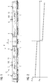
- the Figure 1 shows a rail vehicle 10, which may be a railroad train consisting of a plurality of single wagons coupled together. Of the rail vehicle 10 is in the Figure 1 only a vehicle head 11 lying at the front in the direction of travel F and a vehicle end 12 at the rear in the direction of travel F are shown.
- the rail vehicle 10 is provided with air conditioning devices 100 which enable air conditioning of the vehicle interior of the rail vehicle 10 and for this purpose allow or control an air flow Q into the vehicle interior.
- the air draft L is based physically on the inertia of the air column located inside the vehicle of the rail vehicle 10 and the fact that the rail vehicle 10 is not hermetically sealed and air can enter or exit the rail vehicle 10 due to leaks, as in FIG Figure 1 is indicated by arrows with the reference numerals A and E.
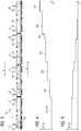
- the Figure 3 shows an embodiment of a rail vehicle 10, which has four parts and in addition to the vehicle head 11 and the vehicle end 12 has two intermediate cars 13.
- the rail vehicle 10 is equipped with controllable air outlet devices in the form of controllable air outlet devices 21 to 28 and a control device 30 that controls the controllable air outlet devices.
- control device 30 The connection between the control device 30 and the air outlet devices 21 to 28 is shown in FIG Figure 3 not explicitly marked.
- the control by the control device 30 is preferably carried out in an electrical manner by means of the Figure 3 electrical control lines, not shown.
- other types of control are also conceivable (e.g. pneumatically or optically).
- the air delivery volume, which the air outlet devices 21 to 28 allow depending on the individual activation by the control device 30, is in the Figure 3 indicated by arrows with the reference symbols L1 to L8.
- the rail vehicle 10 moves according to Figure 3 along the direction of travel F and is braked, so there will be a movement of the air column within the vehicle interior, as in connection with the Figure 1 has already been explained as an example above.
- the control device 30 will control the controllable air outlet devices 21 to 28 individually, depending on the respective position within the rail vehicle 10 and try through a locally distributed air outlet from inside the vehicle, in accordance with the draft L Figure 1 counteract.
- the Figure 4 shows an embodiment of a control profile SP (x), which is suitable for controlling the air outlet devices 21 to 28 by the control device 30 in the event of a braking maneuver.
- the air outlet rate of the controllable air outlet devices 21 to 28, which are arranged offset or spaced along the longitudinal direction X of the rail vehicle 10, is shown. It can be seen that for the compensation of the air draft L (cf. Figure 1 ) When braking the rail vehicle 10, the control device 30 will control the air outlet devices 21 to 28 such that the air outlet devices located in the area of the vehicle end 12 or in the rear part of the rail vehicle 10 have a higher air outlet rate than those in the area of the vehicle head 11 or in the front Air outlet devices located part of the rail vehicle 10.
- the air outlet rates preferably increase along the longitudinal direction X of the rail vehicle 10 and reach a value W7 in the region of the vehicle end 12, for example.
- the air outlet rates of the middle air outlet devices 23 to 27 are identified in FIG. 4 by the reference symbols W2 to W6.
- the control profile SP (x) refers by way of example to one of many possible braking maneuvers of the rail vehicle 10; For different braking maneuvers (e.g. slow entry into a station, rapid entry into a station, reduction in speed due to a reduction in the permissible maximum speed, emergency braking), different control profiles SP (x) are preferably stored in the control device 10, so that depending on the braking maneuvers performed or to be carried out, a suitable or the most suitable control profile SP (x) can be selected.
- braking maneuvers e.g. slow entry into a station, rapid entry into a station, reduction in speed due to a reduction in the permissible maximum speed, emergency braking
- different control profiles SP (x) are preferably stored in the control device 10, so that depending on the braking maneuvers performed or to be carried out, a suitable or the most suitable control profile SP (x) can be selected.
- the control profile SP (x) refers by way of example to one of many conceivable acceleration maneuvers of the rail vehicle 10; For different acceleration maneuvers (e.g. slow starting when leaving a station, swift exit from a station, increasing the speed due to an increase in the permissible maximum speed), different control profiles SP (x) are preferably stored in the control device 10, so that depending on the a suitable or the most suitable control profile SP (x) can be selected.
- acceleration maneuvers e.g. slow starting when leaving a station, swift exit from a station, increasing the speed due to an increase in the permissible maximum speed
- different control profiles SP (x) are preferably stored in the control device 10, so that depending on the a suitable or the most suitable control profile SP (x) can be selected.
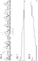
- the Figure 6 shows an embodiment of a rail vehicle 10, in which controllable air inlet devices 41 to 48 are provided to compensate for a draft when accelerating or braking the rail vehicle 10, which are controlled by a control device 30 depending on the driving situation.
- the air delivery volume, which the controllable air inlet devices 41 to 48 allow, depending on the control by the control device 30, is in the Figure 6 marked with the reference symbols L1 to L8.
- control device 30 will actuate the air inlet devices 41 to 48 individually, specifically depending on their spatial position along the longitudinal direction X in the rail vehicle 10, in order to avoid a draft that occurs inside the vehicle or to counteract this.
- the control device 30 can, for example, use control profiles that are stored in the control device 30 or externally.
- the Figure 7 shows an embodiment of a control profile SP (x), which represents the control of the controllable air inlet devices 41 to 48 in the rail vehicle 10 according to Figure 6 when braking.
- a control profile SP x
- the air intake devices located at the front in the direction of travel F are operated with a larger air delivery volume than the air intake devices located at the rear in the direction of travel F.
- the in the Figure 1 Air movement shown are counteracted from the rear of the rail vehicle 10 to the front, so that a draft caused by inertia is compensated or braked by a local pressure increase.
- the Figure 8 shows an example of a control profile that the control device 30 of the rail vehicle 10 according to Figure 6 can be used when the rail vehicle 10 is accelerated. It can be seen that the air inlet devices located at the rear in the direction of travel F are operated with a larger air delivery volume than the air inlet devices located at the front in the direction of travel F. By introducing or admitting air into the rear part of the rail vehicle 10, the air column can move due to inertia be counteracted from the front part of the rail vehicle 10 into the rear part.
- the air outlet devices 200 are spaced or staggered when viewed along the longitudinal direction X of the rail vehicle 10.
- the air passage device 200 located at the front in the direction of travel F is located at a point X1 and the most controllable air passage device 200 located at the rear is located at a point Xm.
- the controllable air passage devices 200 are controlled by a control device 30, which includes a computing device 31 and a memory 32.
- a large number n of control profiles SP1 (x), SP2 (x) ..., SPn-1 (x), SPn (x) is stored in the memory 32.
- the computing device 31 is connected to the memory 32 and is acted upon by a control input 31a with a time-dependent driving parameter indicating the respective driving situation of the rail vehicle 10, which is, for example, the respective route point S (t), the respective speed v (t) or the respective acceleration a (t) can act.
- a time-dependent driving parameter indicating the respective driving situation of the rail vehicle 10
- the computing device 31 determines whether the rail vehicle 10 is being accelerated or braked (depending on the type of the driving parameter, for example by differentiation) and, depending on the size of the acceleration or the size of the deceleration, selects a control profile SP1 suitable for the respective driving situation ( x) to SPn (x).
- the computing device 31 controls the air passage devices 200 along the longitudinal direction X of the rail vehicle 10, as is the case in connection with FIGS Figures 1 to 8 has been explained above whereby the inertia-related occurrence of a draft L within the rail vehicle 10 during acceleration or deceleration is avoided or at least reduced.
- Control profiles SP1 (x) to SPn (x) shown can also be stored in the memory 32 for each of the air passage devices 200, an individual control function with which the respective air flow rate L (xi) is dependent on a time-dependent driving parameter, for example one of the above-mentioned driving parameters (e.g. acceleration value a (t)) and the position Xi of the respective air outlet device 200 is individually calculated for the air outlet device.
Landscapes
- Engineering & Computer Science (AREA)
- Mechanical Engineering (AREA)
- Electric Propulsion And Braking For Vehicles (AREA)
- Air-Conditioning For Vehicles (AREA)
- Regulating Braking Force (AREA)
Priority Applications (1)
| Application Number | Priority Date | Filing Date | Title |
|---|---|---|---|
| PL15719639T PL3122609T3 (pl) | 2014-05-20 | 2015-04-16 | Pojazd z systemem wentylacyjnym |
Applications Claiming Priority (2)
| Application Number | Priority Date | Filing Date | Title |
|---|---|---|---|
| DE102014209549.2A DE102014209549A1 (de) | 2014-05-20 | 2014-05-20 | Fahrzeug mit Belüftungssystem |
| PCT/EP2015/058317 WO2015176879A1 (de) | 2014-05-20 | 2015-04-16 | Fahrzeug mit belüftungssystem |
Publications (2)
| Publication Number | Publication Date |
|---|---|
| EP3122609A1 EP3122609A1 (de) | 2017-02-01 |
| EP3122609B1 true EP3122609B1 (de) | 2020-01-15 |
Family
ID=53039387
Family Applications (1)
| Application Number | Title | Priority Date | Filing Date |
|---|---|---|---|
| EP15719639.5A Active EP3122609B1 (de) | 2014-05-20 | 2015-04-16 | Fahrzeug mit belüftungssystem |
Country Status (9)
| Country | Link |
|---|---|
| EP (1) | EP3122609B1 (da) |
| CN (1) | CN206501855U (da) |
| DE (1) | DE102014209549A1 (da) |
| DK (1) | DK3122609T3 (da) |
| ES (1) | ES2781214T3 (da) |
| PL (1) | PL3122609T3 (da) |
| PT (1) | PT3122609T (da) |
| RU (1) | RU177453U1 (da) |
| WO (1) | WO2015176879A1 (da) |
Family Cites Families (7)
| Publication number | Priority date | Publication date | Assignee | Title |
|---|---|---|---|---|
| EP0523752A1 (en) * | 1987-11-02 | 1993-01-20 | Hitachi, Ltd. | Ventilating equipment for rolling stock |
| FR2728526B1 (fr) * | 1994-12-22 | 1997-01-31 | Gec Alsthom Transport Sa | Dispositif et procede de suppression des variations brutales de pression dans les vehicules |
| FR2793205B1 (fr) * | 1999-05-06 | 2001-08-10 | Soprano | Dispositif de protection contre les ondes de pression dans les vehicules de transport de personnes |
| DE10208006A1 (de) * | 2002-02-26 | 2003-09-11 | Lutz Boeck | Verdrängungslüfter-Druckschutzsystem |
| DE102004008437A1 (de) * | 2003-02-20 | 2004-09-02 | Coldewey, Maik, Dipl.-Ing. | Ventilschließ-Drehzahländerungs-Drosseldruckschutzsystem |
| RU87674U1 (ru) * | 2009-03-30 | 2009-10-20 | Общество с ограниченной ответственностью Научно-производственное предприятие "Циркон-Сервис" | Система кондиционирования воздуха пассажирского вагона |
| DE102011055684B4 (de) * | 2011-11-24 | 2021-11-11 | Continental Teves Ag & Co. Ohg | Verfahren zum Betrieb einer Belüftungseinrichtung eines Fahrzeugs |
-
2014
- 2014-05-20 DE DE102014209549.2A patent/DE102014209549A1/de not_active Withdrawn
-
2015
- 2015-04-16 PT PT157196395T patent/PT3122609T/pt unknown
- 2015-04-16 RU RU2016149811U patent/RU177453U1/ru active
- 2015-04-16 ES ES15719639T patent/ES2781214T3/es active Active
- 2015-04-16 CN CN201590000621.8U patent/CN206501855U/zh not_active Expired - Lifetime
- 2015-04-16 PL PL15719639T patent/PL3122609T3/pl unknown
- 2015-04-16 EP EP15719639.5A patent/EP3122609B1/de active Active
- 2015-04-16 DK DK15719639.5T patent/DK3122609T3/da active
- 2015-04-16 WO PCT/EP2015/058317 patent/WO2015176879A1/de not_active Ceased
Non-Patent Citations (1)
| Title |
|---|
| None * |
Also Published As
| Publication number | Publication date |
|---|---|
| ES2781214T3 (es) | 2020-08-31 |
| EP3122609A1 (de) | 2017-02-01 |
| WO2015176879A1 (de) | 2015-11-26 |
| CN206501855U (zh) | 2017-09-19 |
| DE102014209549A1 (de) | 2015-11-26 |
| PT3122609T (pt) | 2020-03-23 |
| RU177453U1 (ru) | 2018-02-21 |
| PL3122609T3 (pl) | 2020-06-29 |
| DK3122609T3 (da) | 2020-04-14 |
Similar Documents
| Publication | Publication Date | Title |
|---|---|---|
| EP3721308B1 (de) | Verfahren zum bewegen einer fahrzeugkolonne auf basis einer der fahrzeugkolonne zugeordneten, vorgebbaren gesamtbetriebsstrategie | |
| DE102018114499B4 (de) | Kraftfahrzeug-Bug | |
| EP3362331B1 (de) | Verfahren zur vorausschauenden umkippverhinderung eines fahrzeugs | |
| DE102018221241A1 (de) | Fahrassistenzsystem für einen Kraftwagen, Kraftwagen und Verfahren zum Betreiben eines Kraftwagens | |
| EP2681096A1 (de) | Verfahren zur kalkulation einer geschwindigkeitsempfehlung durch ein in einem schienenfahrzeug eingebautes fahrerassistenzsystem | |
| DE102014107402A1 (de) | Schienenfahrzeugbremssystem mit einer Konditionierungseinrichtung, Konditionierungseinrichtung und Verfahren zum Betreiben einer Konditionierungseinrichtung | |
| DE102019101443A1 (de) | Verfahren zum Steuern einer Fahrzeugkolonne bei einer Notbremsung | |
| EP4344970A1 (de) | Sollkraftbestimmungsverfahren | |
| DE102015009374A1 (de) | Kraftfahrzeug mit Bremskühlung | |
| DE102014002552A1 (de) | Luftleitvorrichtung zur Beeinflussung der Aerodynamik eines Kraftwagens | |
| EP3902730B1 (de) | Fahrzeug | |
| DE112013007135B4 (de) | Schienenfahrzeug, das Seitenkraft reduzieren kann, und Verfahren zum Reduzieren von Seitenkraft | |
| EP3122609B1 (de) | Fahrzeug mit belüftungssystem | |
| DE102008036039B4 (de) | Verfahren zur Überwachung und Ansteuerung eines Positions-Stellers | |
| EP2848478A2 (de) | Flussumschalter | |
| DE102004048993B4 (de) | System und Verfahren zur Steuerung von schienengebundenen Fahrzeugen, insbesondere von Zügen, mittels einer Steuerzentrale, in Abhängigkeit vom Zustand des Fahrwegs, insbesondere des verfügbaren Reibwertes | |
| DE102016011243A1 (de) | Verfahren zum Betrieb eines Assistenzsystems | |
| EP3558768B1 (de) | Verfahren zur adhäsionsverbesserung eines schienenfahrzeugs durch konditionierung ausgewählter achse(n) | |
| DE102019131222A1 (de) | Routenzug zum Transportieren von Gegenständen sowie Verfahren und Computerprogramm zum Verändern der Größe des Überwachungsfelds einer Moduleinheit | |
| DE102019116445A1 (de) | Verfahren, Computerprogrammprodukt und System zur Linderung von Kinetose eines Fahrzeuginsassen sowie ein hiermit ausgestattetes Kraftfahrzeug | |
| EP3040256B1 (de) | Radkasten eines kraftfahrzeuges | |
| DE102018000781A1 (de) | Verfahren zum Betrieb mehrerer Fahrzeuge | |
| DE102019211938B4 (de) | Luftleitanordnung für ein Fahrzeug | |
| DE102010041440A1 (de) | Fahrzeug mit einer mit Hilfe eines Kühlluftmassenstrms gekühlten Komponente | |
| DE102017217408A1 (de) | Schienenfahrzeug zur Personenbeförderung |
Legal Events
| Date | Code | Title | Description |
|---|---|---|---|
| STAA | Information on the status of an ep patent application or granted ep patent |
Free format text: STATUS: THE INTERNATIONAL PUBLICATION HAS BEEN MADE |
|
| PUAI | Public reference made under article 153(3) epc to a published international application that has entered the european phase |
Free format text: ORIGINAL CODE: 0009012 |
|
| STAA | Information on the status of an ep patent application or granted ep patent |
Free format text: STATUS: REQUEST FOR EXAMINATION WAS MADE |
|
| 17P | Request for examination filed |
Effective date: 20161028 |
|
| AK | Designated contracting states |
Kind code of ref document: A1 Designated state(s): AL AT BE BG CH CY CZ DE DK EE ES FI FR GB GR HR HU IE IS IT LI LT LU LV MC MK MT NL NO PL PT RO RS SE SI SK SM TR |
|
| AX | Request for extension of the european patent |
Extension state: BA ME |
|
| DAV | Request for validation of the european patent (deleted) | ||
| DAX | Request for extension of the european patent (deleted) | ||
| RAP1 | Party data changed (applicant data changed or rights of an application transferred) |
Owner name: SIEMENS AKTIENGESELLSCHAFT |
|
| RAP1 | Party data changed (applicant data changed or rights of an application transferred) |
Owner name: SIEMENS MOBILITY GMBH |
|
| GRAP | Despatch of communication of intention to grant a patent |
Free format text: ORIGINAL CODE: EPIDOSNIGR1 |
|
| STAA | Information on the status of an ep patent application or granted ep patent |
Free format text: STATUS: GRANT OF PATENT IS INTENDED |
|
| INTG | Intention to grant announced |
Effective date: 20190918 |
|
| GRAS | Grant fee paid |
Free format text: ORIGINAL CODE: EPIDOSNIGR3 |
|
| GRAA | (expected) grant |
Free format text: ORIGINAL CODE: 0009210 |
|
| STAA | Information on the status of an ep patent application or granted ep patent |
Free format text: STATUS: THE PATENT HAS BEEN GRANTED |
|
| AK | Designated contracting states |
Kind code of ref document: B1 Designated state(s): AL AT BE BG CH CY CZ DE DK EE ES FI FR GB GR HR HU IE IS IT LI LT LU LV MC MK MT NL NO PL PT RO RS SE SI SK SM TR |
|
| REG | Reference to a national code |
Ref country code: CH Ref legal event code: EP Ref country code: GB Ref legal event code: FG4D Free format text: NOT ENGLISH |
|
| REG | Reference to a national code |
Ref country code: IE Ref legal event code: FG4D Free format text: LANGUAGE OF EP DOCUMENT: GERMAN |
|
| REG | Reference to a national code |
Ref country code: DE Ref legal event code: R096 Ref document number: 502015011532 Country of ref document: DE |
|
| REG | Reference to a national code |
Ref country code: CH Ref legal event code: NV Representative=s name: SIEMENS SCHWEIZ AG, CH |
|
| REG | Reference to a national code |
Ref country code: AT Ref legal event code: REF Ref document number: 1224918 Country of ref document: AT Kind code of ref document: T Effective date: 20200215 |
|
| REG | Reference to a national code |
Ref country code: PT Ref legal event code: SC4A Ref document number: 3122609 Country of ref document: PT Date of ref document: 20200323 Kind code of ref document: T Free format text: AVAILABILITY OF NATIONAL TRANSLATION Effective date: 20200309 |
|
| REG | Reference to a national code |
Ref country code: NL Ref legal event code: FP |
|
| REG | Reference to a national code |
Ref country code: DK Ref legal event code: T3 Effective date: 20200407 |
|
| REG | Reference to a national code |
Ref country code: LT Ref legal event code: MG4D |
|
| PG25 | Lapsed in a contracting state [announced via postgrant information from national office to epo] |
Ref country code: RS Free format text: LAPSE BECAUSE OF FAILURE TO SUBMIT A TRANSLATION OF THE DESCRIPTION OR TO PAY THE FEE WITHIN THE PRESCRIBED TIME-LIMIT Effective date: 20200115 Ref country code: FI Free format text: LAPSE BECAUSE OF FAILURE TO SUBMIT A TRANSLATION OF THE DESCRIPTION OR TO PAY THE FEE WITHIN THE PRESCRIBED TIME-LIMIT Effective date: 20200115 Ref country code: NO Free format text: LAPSE BECAUSE OF FAILURE TO SUBMIT A TRANSLATION OF THE DESCRIPTION OR TO PAY THE FEE WITHIN THE PRESCRIBED TIME-LIMIT Effective date: 20200415 |
|
| PG25 | Lapsed in a contracting state [announced via postgrant information from national office to epo] |
Ref country code: BG Free format text: LAPSE BECAUSE OF FAILURE TO SUBMIT A TRANSLATION OF THE DESCRIPTION OR TO PAY THE FEE WITHIN THE PRESCRIBED TIME-LIMIT Effective date: 20200415 Ref country code: HR Free format text: LAPSE BECAUSE OF FAILURE TO SUBMIT A TRANSLATION OF THE DESCRIPTION OR TO PAY THE FEE WITHIN THE PRESCRIBED TIME-LIMIT Effective date: 20200115 Ref country code: LV Free format text: LAPSE BECAUSE OF FAILURE TO SUBMIT A TRANSLATION OF THE DESCRIPTION OR TO PAY THE FEE WITHIN THE PRESCRIBED TIME-LIMIT Effective date: 20200115 Ref country code: SE Free format text: LAPSE BECAUSE OF FAILURE TO SUBMIT A TRANSLATION OF THE DESCRIPTION OR TO PAY THE FEE WITHIN THE PRESCRIBED TIME-LIMIT Effective date: 20200115 Ref country code: IS Free format text: LAPSE BECAUSE OF FAILURE TO SUBMIT A TRANSLATION OF THE DESCRIPTION OR TO PAY THE FEE WITHIN THE PRESCRIBED TIME-LIMIT Effective date: 20200515 Ref country code: GR Free format text: LAPSE BECAUSE OF FAILURE TO SUBMIT A TRANSLATION OF THE DESCRIPTION OR TO PAY THE FEE WITHIN THE PRESCRIBED TIME-LIMIT Effective date: 20200416 |
|
| REG | Reference to a national code |
Ref country code: ES Ref legal event code: FG2A Ref document number: 2781214 Country of ref document: ES Kind code of ref document: T3 Effective date: 20200831 |
|
| REG | Reference to a national code |
Ref country code: DE Ref legal event code: R097 Ref document number: 502015011532 Country of ref document: DE |
|
| PG25 | Lapsed in a contracting state [announced via postgrant information from national office to epo] |
Ref country code: SM Free format text: LAPSE BECAUSE OF FAILURE TO SUBMIT A TRANSLATION OF THE DESCRIPTION OR TO PAY THE FEE WITHIN THE PRESCRIBED TIME-LIMIT Effective date: 20200115 Ref country code: RO Free format text: LAPSE BECAUSE OF FAILURE TO SUBMIT A TRANSLATION OF THE DESCRIPTION OR TO PAY THE FEE WITHIN THE PRESCRIBED TIME-LIMIT Effective date: 20200115 Ref country code: SK Free format text: LAPSE BECAUSE OF FAILURE TO SUBMIT A TRANSLATION OF THE DESCRIPTION OR TO PAY THE FEE WITHIN THE PRESCRIBED TIME-LIMIT Effective date: 20200115 Ref country code: EE Free format text: LAPSE BECAUSE OF FAILURE TO SUBMIT A TRANSLATION OF THE DESCRIPTION OR TO PAY THE FEE WITHIN THE PRESCRIBED TIME-LIMIT Effective date: 20200115 Ref country code: LT Free format text: LAPSE BECAUSE OF FAILURE TO SUBMIT A TRANSLATION OF THE DESCRIPTION OR TO PAY THE FEE WITHIN THE PRESCRIBED TIME-LIMIT Effective date: 20200115 |
|
| PLBE | No opposition filed within time limit |
Free format text: ORIGINAL CODE: 0009261 |
|
| STAA | Information on the status of an ep patent application or granted ep patent |
Free format text: STATUS: NO OPPOSITION FILED WITHIN TIME LIMIT |
|
| PG25 | Lapsed in a contracting state [announced via postgrant information from national office to epo] |
Ref country code: MC Free format text: LAPSE BECAUSE OF FAILURE TO SUBMIT A TRANSLATION OF THE DESCRIPTION OR TO PAY THE FEE WITHIN THE PRESCRIBED TIME-LIMIT Effective date: 20200115 |
|
| 26N | No opposition filed |
Effective date: 20201016 |
|
| PG25 | Lapsed in a contracting state [announced via postgrant information from national office to epo] |
Ref country code: LU Free format text: LAPSE BECAUSE OF NON-PAYMENT OF DUE FEES Effective date: 20200416 |
|
| PG25 | Lapsed in a contracting state [announced via postgrant information from national office to epo] |
Ref country code: SI Free format text: LAPSE BECAUSE OF FAILURE TO SUBMIT A TRANSLATION OF THE DESCRIPTION OR TO PAY THE FEE WITHIN THE PRESCRIBED TIME-LIMIT Effective date: 20200115 |
|
| PG25 | Lapsed in a contracting state [announced via postgrant information from national office to epo] |
Ref country code: IE Free format text: LAPSE BECAUSE OF NON-PAYMENT OF DUE FEES Effective date: 20200416 |
|
| PG25 | Lapsed in a contracting state [announced via postgrant information from national office to epo] |
Ref country code: MT Free format text: LAPSE BECAUSE OF FAILURE TO SUBMIT A TRANSLATION OF THE DESCRIPTION OR TO PAY THE FEE WITHIN THE PRESCRIBED TIME-LIMIT Effective date: 20200115 Ref country code: CY Free format text: LAPSE BECAUSE OF FAILURE TO SUBMIT A TRANSLATION OF THE DESCRIPTION OR TO PAY THE FEE WITHIN THE PRESCRIBED TIME-LIMIT Effective date: 20200115 |
|
| PG25 | Lapsed in a contracting state [announced via postgrant information from national office to epo] |
Ref country code: MK Free format text: LAPSE BECAUSE OF FAILURE TO SUBMIT A TRANSLATION OF THE DESCRIPTION OR TO PAY THE FEE WITHIN THE PRESCRIBED TIME-LIMIT Effective date: 20200115 Ref country code: AL Free format text: LAPSE BECAUSE OF FAILURE TO SUBMIT A TRANSLATION OF THE DESCRIPTION OR TO PAY THE FEE WITHIN THE PRESCRIBED TIME-LIMIT Effective date: 20200115 |
|
| PGFP | Annual fee paid to national office [announced via postgrant information from national office to epo] |
Ref country code: PT Payment date: 20230306 Year of fee payment: 9 |
|
| PGFP | Annual fee paid to national office [announced via postgrant information from national office to epo] |
Ref country code: DK Payment date: 20230421 Year of fee payment: 9 |
|
| PGFP | Annual fee paid to national office [announced via postgrant information from national office to epo] |
Ref country code: TR Payment date: 20230414 Year of fee payment: 9 Ref country code: PL Payment date: 20230406 Year of fee payment: 9 Ref country code: AT Payment date: 20230307 Year of fee payment: 9 |
|
| PGFP | Annual fee paid to national office [announced via postgrant information from national office to epo] |
Ref country code: BE Payment date: 20230419 Year of fee payment: 9 |
|
| REG | Reference to a national code |
Ref country code: DK Ref legal event code: EBP Effective date: 20240430 |
|
| PG25 | Lapsed in a contracting state [announced via postgrant information from national office to epo] |
Ref country code: PT Free format text: LAPSE BECAUSE OF NON-PAYMENT OF DUE FEES Effective date: 20241016 |
|
| REG | Reference to a national code |
Ref country code: AT Ref legal event code: MM01 Ref document number: 1224918 Country of ref document: AT Kind code of ref document: T Effective date: 20240416 |
|
| REG | Reference to a national code |
Ref country code: BE Ref legal event code: MM Effective date: 20240430 |
|
| PG25 | Lapsed in a contracting state [announced via postgrant information from national office to epo] |
Ref country code: PT Free format text: LAPSE BECAUSE OF NON-PAYMENT OF DUE FEES Effective date: 20241016 |
|
| PG25 | Lapsed in a contracting state [announced via postgrant information from national office to epo] |
Ref country code: BE Free format text: LAPSE BECAUSE OF NON-PAYMENT OF DUE FEES Effective date: 20240430 |
|
| PG25 | Lapsed in a contracting state [announced via postgrant information from national office to epo] |
Ref country code: AT Free format text: LAPSE BECAUSE OF NON-PAYMENT OF DUE FEES Effective date: 20240416 |
|
| PG25 | Lapsed in a contracting state [announced via postgrant information from national office to epo] |
Ref country code: BE Free format text: LAPSE BECAUSE OF NON-PAYMENT OF DUE FEES Effective date: 20240430 Ref country code: AT Free format text: LAPSE BECAUSE OF NON-PAYMENT OF DUE FEES Effective date: 20240416 |
|
| PG25 | Lapsed in a contracting state [announced via postgrant information from national office to epo] |
Ref country code: DK Free format text: LAPSE BECAUSE OF NON-PAYMENT OF DUE FEES Effective date: 20240430 |
|
| PG25 | Lapsed in a contracting state [announced via postgrant information from national office to epo] |
Ref country code: PL Free format text: LAPSE BECAUSE OF NON-PAYMENT OF DUE FEES Effective date: 20240416 |
|
| PGFP | Annual fee paid to national office [announced via postgrant information from national office to epo] |
Ref country code: NL Payment date: 20250403 Year of fee payment: 11 |
|
| PGFP | Annual fee paid to national office [announced via postgrant information from national office to epo] |
Ref country code: DE Payment date: 20250620 Year of fee payment: 11 |
|
| PGFP | Annual fee paid to national office [announced via postgrant information from national office to epo] |
Ref country code: GB Payment date: 20250507 Year of fee payment: 11 |
|
| PGFP | Annual fee paid to national office [announced via postgrant information from national office to epo] |
Ref country code: IT Payment date: 20250417 Year of fee payment: 11 |
|
| PGFP | Annual fee paid to national office [announced via postgrant information from national office to epo] |
Ref country code: FR Payment date: 20250411 Year of fee payment: 11 |
|
| PGFP | Annual fee paid to national office [announced via postgrant information from national office to epo] |
Ref country code: CZ Payment date: 20250407 Year of fee payment: 11 |
|
| REG | Reference to a national code |
Ref country code: DE Ref legal event code: R081 Ref document number: 502015011532 Country of ref document: DE Owner name: SIEMENS MOBILITY GMBH, DE Free format text: FORMER OWNER: SIEMENS MOBILITY GMBH, 81739 MUENCHEN, DE |
|
| PGFP | Annual fee paid to national office [announced via postgrant information from national office to epo] |
Ref country code: ES Payment date: 20250721 Year of fee payment: 11 |
|
| PGFP | Annual fee paid to national office [announced via postgrant information from national office to epo] |
Ref country code: CH Payment date: 20250709 Year of fee payment: 11 |