EP3122983B1 - Intelligente verglasung mit lichtabschirmung - Google Patents
Intelligente verglasung mit lichtabschirmung Download PDFInfo
- Publication number
- EP3122983B1 EP3122983B1 EP15715593.8A EP15715593A EP3122983B1 EP 3122983 B1 EP3122983 B1 EP 3122983B1 EP 15715593 A EP15715593 A EP 15715593A EP 3122983 B1 EP3122983 B1 EP 3122983B1
- Authority
- EP
- European Patent Office
- Prior art keywords
- light
- active material
- optically active
- substrate
- light emitting
- Prior art date
- Legal status (The legal status is an assumption and is not a legal conclusion. Google has not performed a legal analysis and makes no representation as to the accuracy of the status listed.)
- Active
Links
Images



Classifications
-
- G—PHYSICS
- G02—OPTICS
- G02F—OPTICAL DEVICES OR ARRANGEMENTS FOR THE CONTROL OF LIGHT BY MODIFICATION OF THE OPTICAL PROPERTIES OF THE MEDIA OF THE ELEMENTS INVOLVED THEREIN; NON-LINEAR OPTICS; FREQUENCY-CHANGING OF LIGHT; OPTICAL LOGIC ELEMENTS; OPTICAL ANALOGUE/DIGITAL CONVERTERS
- G02F1/00—Devices or arrangements for the control of the intensity, colour, phase, polarisation or direction of light arriving from an independent light source, e.g. switching, gating or modulating; Non-linear optics
- G02F1/01—Devices or arrangements for the control of the intensity, colour, phase, polarisation or direction of light arriving from an independent light source, e.g. switching, gating or modulating; Non-linear optics for the control of the intensity, phase, polarisation or colour
- G02F1/13—Devices or arrangements for the control of the intensity, colour, phase, polarisation or direction of light arriving from an independent light source, e.g. switching, gating or modulating; Non-linear optics for the control of the intensity, phase, polarisation or colour based on liquid crystals, e.g. single liquid crystal display cells
- G02F1/137—Devices or arrangements for the control of the intensity, colour, phase, polarisation or direction of light arriving from an independent light source, e.g. switching, gating or modulating; Non-linear optics for the control of the intensity, phase, polarisation or colour based on liquid crystals, e.g. single liquid crystal display cells characterised by the electro-optical or magneto-optical effect, e.g. field-induced phase transition, orientation effect, guest-host interaction or dynamic scattering
-
- E—FIXED CONSTRUCTIONS
- E06—DOORS, WINDOWS, SHUTTERS, OR ROLLER BLINDS IN GENERAL; LADDERS
- E06B—FIXED OR MOVABLE CLOSURES FOR OPENINGS IN BUILDINGS, VEHICLES, FENCES OR LIKE ENCLOSURES IN GENERAL, e.g. DOORS, WINDOWS, BLINDS, GATES
- E06B9/00—Screening or protective devices for wall or similar openings, with or without operating or securing mechanisms; Closures of similar construction
- E06B9/24—Screens or other constructions affording protection against light, especially against sunshine; Similar screens for privacy or appearance; Slat blinds
-
- G—PHYSICS
- G02—OPTICS
- G02F—OPTICAL DEVICES OR ARRANGEMENTS FOR THE CONTROL OF LIGHT BY MODIFICATION OF THE OPTICAL PROPERTIES OF THE MEDIA OF THE ELEMENTS INVOLVED THEREIN; NON-LINEAR OPTICS; FREQUENCY-CHANGING OF LIGHT; OPTICAL LOGIC ELEMENTS; OPTICAL ANALOGUE/DIGITAL CONVERTERS
- G02F1/00—Devices or arrangements for the control of the intensity, colour, phase, polarisation or direction of light arriving from an independent light source, e.g. switching, gating or modulating; Non-linear optics
- G02F1/01—Devices or arrangements for the control of the intensity, colour, phase, polarisation or direction of light arriving from an independent light source, e.g. switching, gating or modulating; Non-linear optics for the control of the intensity, phase, polarisation or colour
- G02F1/13—Devices or arrangements for the control of the intensity, colour, phase, polarisation or direction of light arriving from an independent light source, e.g. switching, gating or modulating; Non-linear optics for the control of the intensity, phase, polarisation or colour based on liquid crystals, e.g. single liquid crystal display cells
- G02F1/133—Constructional arrangements; Operation of liquid crystal cells; Circuit arrangements
- G02F1/1333—Constructional arrangements; Manufacturing methods
- G02F1/1335—Structural association of cells with optical devices, e.g. polarisers or reflectors
- G02F1/1336—Illuminating devices
- G02F1/133615—Edge-illuminating devices, i.e. illuminating from the side
-
- G—PHYSICS
- G02—OPTICS
- G02F—OPTICAL DEVICES OR ARRANGEMENTS FOR THE CONTROL OF LIGHT BY MODIFICATION OF THE OPTICAL PROPERTIES OF THE MEDIA OF THE ELEMENTS INVOLVED THEREIN; NON-LINEAR OPTICS; FREQUENCY-CHANGING OF LIGHT; OPTICAL LOGIC ELEMENTS; OPTICAL ANALOGUE/DIGITAL CONVERTERS
- G02F1/00—Devices or arrangements for the control of the intensity, colour, phase, polarisation or direction of light arriving from an independent light source, e.g. switching, gating or modulating; Non-linear optics
- G02F1/01—Devices or arrangements for the control of the intensity, colour, phase, polarisation or direction of light arriving from an independent light source, e.g. switching, gating or modulating; Non-linear optics for the control of the intensity, phase, polarisation or colour
- G02F1/13—Devices or arrangements for the control of the intensity, colour, phase, polarisation or direction of light arriving from an independent light source, e.g. switching, gating or modulating; Non-linear optics for the control of the intensity, phase, polarisation or colour based on liquid crystals, e.g. single liquid crystal display cells
- G02F1/133—Constructional arrangements; Operation of liquid crystal cells; Circuit arrangements
- G02F1/1333—Constructional arrangements; Manufacturing methods
- G02F1/1339—Gaskets; Spacers; Sealing of cells
-
- G—PHYSICS
- G02—OPTICS
- G02F—OPTICAL DEVICES OR ARRANGEMENTS FOR THE CONTROL OF LIGHT BY MODIFICATION OF THE OPTICAL PROPERTIES OF THE MEDIA OF THE ELEMENTS INVOLVED THEREIN; NON-LINEAR OPTICS; FREQUENCY-CHANGING OF LIGHT; OPTICAL LOGIC ELEMENTS; OPTICAL ANALOGUE/DIGITAL CONVERTERS
- G02F1/00—Devices or arrangements for the control of the intensity, colour, phase, polarisation or direction of light arriving from an independent light source, e.g. switching, gating or modulating; Non-linear optics
- G02F1/01—Devices or arrangements for the control of the intensity, colour, phase, polarisation or direction of light arriving from an independent light source, e.g. switching, gating or modulating; Non-linear optics for the control of the intensity, phase, polarisation or colour
- G02F1/15—Devices or arrangements for the control of the intensity, colour, phase, polarisation or direction of light arriving from an independent light source, e.g. switching, gating or modulating; Non-linear optics for the control of the intensity, phase, polarisation or colour based on an electrochromic effect
- G02F1/153—Constructional details
-
- E—FIXED CONSTRUCTIONS
- E06—DOORS, WINDOWS, SHUTTERS, OR ROLLER BLINDS IN GENERAL; LADDERS
- E06B—FIXED OR MOVABLE CLOSURES FOR OPENINGS IN BUILDINGS, VEHICLES, FENCES OR LIKE ENCLOSURES IN GENERAL, e.g. DOORS, WINDOWS, BLINDS, GATES
- E06B9/00—Screening or protective devices for wall or similar openings, with or without operating or securing mechanisms; Closures of similar construction
- E06B9/24—Screens or other constructions affording protection against light, especially against sunshine; Similar screens for privacy or appearance; Slat blinds
- E06B2009/2464—Screens or other constructions affording protection against light, especially against sunshine; Similar screens for privacy or appearance; Slat blinds featuring transparency control by applying voltage, e.g. LCD, electrochromic panels
-
- E—FIXED CONSTRUCTIONS
- E06—DOORS, WINDOWS, SHUTTERS, OR ROLLER BLINDS IN GENERAL; LADDERS
- E06B—FIXED OR MOVABLE CLOSURES FOR OPENINGS IN BUILDINGS, VEHICLES, FENCES OR LIKE ENCLOSURES IN GENERAL, e.g. DOORS, WINDOWS, BLINDS, GATES
- E06B9/00—Screening or protective devices for wall or similar openings, with or without operating or securing mechanisms; Closures of similar construction
- E06B9/24—Screens or other constructions affording protection against light, especially against sunshine; Similar screens for privacy or appearance; Slat blinds
- E06B2009/247—Electrically powered illumination
-
- G—PHYSICS
- G02—OPTICS
- G02F—OPTICAL DEVICES OR ARRANGEMENTS FOR THE CONTROL OF LIGHT BY MODIFICATION OF THE OPTICAL PROPERTIES OF THE MEDIA OF THE ELEMENTS INVOLVED THEREIN; NON-LINEAR OPTICS; FREQUENCY-CHANGING OF LIGHT; OPTICAL LOGIC ELEMENTS; OPTICAL ANALOGUE/DIGITAL CONVERTERS
- G02F1/00—Devices or arrangements for the control of the intensity, colour, phase, polarisation or direction of light arriving from an independent light source, e.g. switching, gating or modulating; Non-linear optics
- G02F1/01—Devices or arrangements for the control of the intensity, colour, phase, polarisation or direction of light arriving from an independent light source, e.g. switching, gating or modulating; Non-linear optics for the control of the intensity, phase, polarisation or colour
- G02F1/13—Devices or arrangements for the control of the intensity, colour, phase, polarisation or direction of light arriving from an independent light source, e.g. switching, gating or modulating; Non-linear optics for the control of the intensity, phase, polarisation or colour based on liquid crystals, e.g. single liquid crystal display cells
- G02F1/137—Devices or arrangements for the control of the intensity, colour, phase, polarisation or direction of light arriving from an independent light source, e.g. switching, gating or modulating; Non-linear optics for the control of the intensity, phase, polarisation or colour based on liquid crystals, e.g. single liquid crystal display cells characterised by the electro-optical or magneto-optical effect, e.g. field-induced phase transition, orientation effect, guest-host interaction or dynamic scattering
- G02F1/13756—Devices or arrangements for the control of the intensity, colour, phase, polarisation or direction of light arriving from an independent light source, e.g. switching, gating or modulating; Non-linear optics for the control of the intensity, phase, polarisation or colour based on liquid crystals, e.g. single liquid crystal display cells characterised by the electro-optical or magneto-optical effect, e.g. field-induced phase transition, orientation effect, guest-host interaction or dynamic scattering the liquid crystal selectively assuming a light-scattering state
Definitions
- This disclosure relates to optical structures and, more particularly, to glazing structures that include a controllable optically active material.
- Windows, doors, partitions, and other structures having controllable tinting have been gaining popularity in the marketplace. These structures are commonly referred to as “smart” structures or “privacy” structures for their ability to transform from a transparent state in which a user can see through the structure to a private state in which viewing is inhibited through the structure. For example, smart windows are being used in high-end automobiles and homes and smart partitions are being used as walls in office spaces to provide controlled privacy and visual darkening.
- a variety of different technologies can be used to provide controlled privacy for a smart structure.
- electrochromic technologies, photochromic technologies, thermochromic technologies, suspended particle technologies, and liquid crystal technologies are all being used in different smart structure applications to provide controllable privacy.
- the technologies generally use an energy source, such as electricity, to transform from a transparent state to a privacy state or vice versa.
- WO 03/067014 discloses a window element, comprising at least one periodically transparent sheet-like element and at least one surface for replay of images, whereby the sheet-like element comprises at least one display which is part of the sheet-like element. In a first state with an operating display a replay of image elements occurs on the sheet-like element and in a second state with a switched-off display a view through the sheet-like element is at least partly possible.
- DE 195 29 737 discloses a room window with variable screening and room lighting, the window has sensors for detecting the ambient light level and a manual control, for optimum regulation of the light intensity within the room via sub-screening and auxiliary room lighting using a number of coloured lamps.
- the light provided by the lamps is reflected into the room via a curved window element with a convex surface on the side facing the room.
- a cavity defined between spaced window panels can be filled with a phosphorescent liquid supplied with electrical pulses for directing light into the room.
- a privacy structure is in the form of a multiple-pane insulating glazing unit having first and second panes of transparent material along with a spacer separating the transparent panes of material to provide a between-pane space.
- the multiple-pane insulating glazing unit carries a layer of electrically controllable optically active material positioned behind one of the panes of transparent material.
- the electronically controllable optically active material can be controllably alternated between a light transmissive state and a privacy state, such as a light scattering or light absorbing state.
- the optically active material When placed in the privacy state, light impinging upon the optically active material can scatter and/or absorb rather than pass through the material, obscuring visibility through the material to an external observer. Although typically intended to completely obscure visibility through the material, in practice, the optically active material may still allow a limited amount of light to directly transmit through the material. This transmitting light may be referred to as residual visibility, as it is the visibility that still remains after the optically active material has been transitioned to a privacy state.
- the multiple-pane insulating glazing unit includes a light emitting element.
- the location of the light emitting element can vary, in one example, the light emitting element is positioned to direct light at the optically active material through at least one of the panes of the multiple-pane insulating glazing unit.
- the light emitting element may be embedded in the spacer of the multiple-pane insulating glazing unit or a frame surrounding the glazing unit and pointed to direct light at an angle with respect to a planar face of the optical active material. In operation, the light emitting element can emit light at the optically active material when the material is placed in its privacy state.
- the light impinging upon the optically active material may reflect off the material, screening any residual visibility through the structure.
- the reflected light may generate light pollution that, when seen by an external observer, prevents the observer's eyes from adjusting to the low level of light still transmitting directly through the structure. This may help mask the residual visibility.
- the light emitting element is positioned to direct light away from the optically active material and toward the direction of an external observer.
- the light emitting element may be embedded in a frame surrounding the glazing unit and pointed to direct light away from the planar face of the optically active material.
- the glazing unit may carry a light emitting element that is a light emitting coating, such as an organic light-emitting diode film, that emits light away from and towards the optically active material. In either case, the light emitting element can emit light away from the optically active material. The emitted light may combine with light passing through the optically active material when in a privacy state, screening residual visibility through the material.
- a glazing structure carries one or more light emitting elements positioned to direct light through a substrate and at an electronically controllable optically active material.
- the glazing structure may be a single-pane glazing structure, a double-pane glazing structure, a triple-pane glazing structure, or may include even more glazing panes. Regardless of the number of panes, the glazing structure can carry the layer of electronically controllable optically active material by sandwiching the material between two substrates.
- the light emitting elements carried by the glazing structure can be positioned to direct light through at least one of the substrates sandwiching the layer of electronically controllable optically active material and, optionally, additional panes of the glazing structure.
- the light emitting elements may activate to shine light at the layer of electronically controllable optically active material when the layer is placed in a privacy state.
- Light reflecting off of the optically active material and/or surfaces of the substrate(s) through which the light is directed may screen direct visible transmittance through the optically active material. Accordingly, this screening may mask residual visibility through the structure.
- the electronically controllable optically active material is transitioned from a privacy state back to a visible state, the light emitting elements may turn off to avoid unnecessary light on the structure.
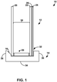
- FIG. 1 is a partial side view illustration of an example glazing structure 10 that includes a multiple-pane insulating glazing unit 12, a frame 14, and at least one light emitting element 16.
- Frame 14 is positioned around an external perimeter of multiple-pane insulating glazing unit 12.
- multiple-pane insulating glazing unit 12 includes a first substrate 20, a second substrate 22, a third substrate 24, and a layer of optically active material 26.
- the layer of optically active material 26 is positioned between the second substrate 22 and the third substrate 24.
- the layer of optically active material 26 can transition from a generally transparent state to a privacy state to control visibility through glazing structure 10. In the privacy state, the layer of optically active material 26 may be dark or hazy, obscuring viewing through the material.
- light emitting element 16 is carried by glazing structure 10 and positioned to direct light at the layer of optically active material 26.
- light emitting element 16 can shine light on the optically active material.
- Light emanating from light emitting element 16 can impinge upon the optically active material in the privacy state and can reflect back in the general direction of emission.
- This reflected light can screen residual light transmitting through glazing structure 10 when the layer of optically active material 26 is in the privacy state. Accordingly, the reflection from light emitting element 16 can help mask or cover residual visibility through the layer of optically active material 26, when the material is in a privacy state.
- the observer may perceive movement or the general shape of the objects, even when the layer of optically active material 26 is in a privacy state.
- light emitting element 16 When light emitting element 16 is active, however, light generated by the element may prevent the observer from perceiving any movement or object shapes.
- Glazing structure 10 can utilize any suitable privacy materials for the layer of optically active material 26.
- optically active material 26 is generally illustrated and described as being a single layer of material, it should be appreciated that a structure in accordance with the disclosure can have one or more layers of optically active material with the same or varying thicknesses.
- optically active material 26 is configured to provide controllable and reversible optical obscuring and lightening.
- Optically active material 26 can change visible transmittance in response to an energy input, such as light, heat, or electricity.
- optically active material 26 may be an electronically controllable optically active material that changes direct visible transmittance in response to changes in electrical energy applied to the material.
- optically active material 26 is formed of an electrochromic material that changes opacity and, hence, light transmission properties, in response to voltage changes applied to the material.
- electrochromic materials are WO 3 and MoO 3 , which are usually colorless when applied to a substrate in thin layers.
- An electrochromic layer may change its optical properties by oxidation or reduction processes. For example, in the case of tungsten oxide, protons can move in the electrochromic layer in response to changing voltage, reducing the tungsten oxide to blue tungsten bronze. The intensity of coloration is varied by the magnitude of charge applied to the layer.
- optically active material 26 is formed of a liquid crystal material.
- liquid crystal materials that can be used as optically active material 26 include polymer dispersed liquid crystal (PDLC) materials and polymer stabilized cholesteric texture (PSCT) materials.
- PDLC polymer dispersed liquid crystal
- PSCT polymer stabilized cholesteric texture
- Polymer dispersed liquid crystals usually involve phase separation of nematic liquid crystal from a homogeneous liquid crystal containing an amount of polymer, sandwiched between electrodes.
- the electrodes can be formed by coating opposed substrates (e.g., second substrate 22 and third substrate 24) with a transparent conductive material. When the electric field is off, the liquid crystals are randomly scattered. This scatters light entering the liquid crystal material and blocks transmission through the material. When a certain voltage is applied between the two electrodes, the liquid crystals homeotropically align and the liquid crystals increase in optical transparency, allowing light to transmit through the crystals.
- the material can either be a normal mode polymer stabilized cholesteric texture material or a reverse mode polymer stabilized cholesteric texture material.
- a normal polymer stabilized cholesteric texture material light is scattered when there is no electrical field applied to the material. If an electric field is applied to the liquid crystal, it turns to a homeotropic state, causing the liquid crystals to reorient themselves parallel to each other along with the electric field. This causes the liquid crystals to increase in optical transparency and allows light to transmit through the crystals.
- the liquid crystals are transparent in the absence of an electric field (e.g., zero electric field) but opaque and scattering upon application of an electric field.
- the layer of optically active material 26 is implemented using a liquid crystal material
- the liquid crystal material turns dark when transitioned to the privacy state.
- a material may absorb light impinging upon the material to prevent an observer on one side of glazing structure 10 from clearly observing activity occurring on the opposite side of the structure.
- Such a material may significantly reduce the total visible transmittance through the material when in the privacy state, as compared to when in the light transmitting state.
- the layer of optically active material 26 turns hazy when transitioned to the privacy state.
- a material may scatter light impinging upon the material to prevent an observer on one side of glazing structure 10 from clearly observing activity occurring on the opposite side of the structure.
- Such a material may significantly reduce regular visible transmittance through the material (which may also be referred to as direct visible transmittance) while only minimally reducing total visible transmittance when in the privacy state, as compared to when in the light transmitting state.
- regular visible transmittance through the material
- the amount of scattered visible light transmitting through the material may increase in the privacy state as compared to the light transmitting state, compensating for the reduced regular visible transmittance through the material.
- Regular or direct visible transmittance may be considered the transmitted visible light that is not scattered or redirected through optically active material 26.
- a suspended particle material is a suspended particle material. Suspended particle materials are typically dark or opaque in a non-activated state but become transparent when a voltage is applied.
- materials that can be used as optically active material 26 include thermochromic materials that change visible transmittance in response to changing temperature and photochromic materials that change visible transmittance in response to changing amounts of light.
- the material can change from a light transmissive state in which insulating glazing unit 12 is intended to be transparent to a privacy state in which visibility through the insulating glazing unit is intended to be blocked.
- Optically active material 26 may exhibit progressively decreasing direct visible transmittance when transitioning from a maximum light transmissive state to a maximum privacy state.
- optically active material 26 may exhibit progressively increasing direct visible transmittance when transitioning from a maximum privacy state to a maximum transmissive state.
- optically active material 26 transitions from a generally transparent transmission state to a generally opaque privacy state may be dictated by a variety of factors, including the specific type of material selected for optically active material 26, the temperature of the material, the electrical voltage applied to the material, and the like.
- optically active material 26 When transitioned to the privacy state, light impinging upon the surface of optically active material 26 may be scattered (e.g., reflected) and/or absorbed rather than transmitted through the material for observation on an opposite side of glazing structure 10.
- Visible transmittance is a measure of the amount of light within the visible spectrum (e.g., ranging from a wavelength of 380 nanometers to 780 nanometers) that passes through the optically active material 26 without scattering. Visible transmittance can be measured in accordance with ASTM E308 and ASTM E903and is generally reported as a percentage.
- the optically active material transitions to complete or zero visible transmittance in the privacy state
- most optically active materials transition to a low direct visible transmittance greater than zero.
- the material may exhibit a direct visible transmittance greater than 0 percent when in a light scattering privacy state (e.g., at maximum opacity), such a direct visible transmittance greater than 0.01 percent, greater than 0.05 percent, or greater than 0.5 percent.
- the layer of optically active material 26 may exhibit a visible transmittance ranging from 0.05 percent to 1 percent when in the light scattering privacy state, such as from 0.1 percent to 0.8 percent. Even at these low direct visible transmittance levels, an unaided human eye may detect light passing through optically active material 26 when in the privacy state. As discussed in more depth below, light emitting element 16 may help compensate for the lack of complete privacy afforded by optically active material 26 to the privacy state.
- glazing structure 10 When installed, glazing structure 10 is designed such that optically active material 26 can transition from a privacy state to a generally transparent state, allowing light to pass from one side of the structure through to another side of the unit. When transitioned to this light transmissive state, light present on one side of glazing structure 10 (e.g., an outdoor side) can pass through to an opposite side of the unit (e.g., an indoor side) for illuminating a space and/or to allow a user positioned to one side of the unit to observe activity occurring on another side of the unit.
- an opposite side of the unit e.g., an indoor side
- optically active material 26 may vary, e.g., depending on the type of material used, in some applications, the material exhibits a direct visible transmittance greater than 60 percent when in a light transmissive state (e.g., at maximum transparency), such as a direct visible transmittance ranging from 65 percent to 85 percent.
- optically active material 26 is physically attached to and carried by multiple-pane insulating glazing unit 12.
- Multiple-pane insulating glazing unit 12 in this example has a first substrate 20, a second substrate 22, and a third substrate 24.
- Multiple-pane insulating glazing unit 12 also includes a spacer 28. Spacer 28 holds first substrate 20 generally parallel to and spaced apart from second substrate 22 to define between-pane space 30. Spacer 28 can extend around the entire perimeter of multiple-pane insulating glazing unit 12 to hermetically seal the between-pane space 30 from gas exchange with a surrounding environment.
- Spacer 28 can be any structure that holds opposed substrates in a spaced apart relationship over the service life of multiple-pane insulating glazing glass unit 12 and seals a between-pane space between the opposed panes of material, e.g., so as to inhibit or eliminate gas exchange between the between-pane space and an environment surrounding insulating glazing unit 12.
- a spacer that can be used as spacer 28 is a tubular spacer positioned between first substrate 20 and second substrate 22.
- the tubular spacer may define a hollow lumen or tube which, in some examples, is filled with desiccant.
- the tubular spacer may have a first side surface adhered (by a first bead of sealant) to first substrate 20 and a second side surface adhered (by a second bead of sealant) to second substrate 22.
- a top surface of the tubular spacer can exposed to between-pane space 30 and, in some examples, includes openings that allow gas within the between-pane space to communicate with desiccating material inside of the spacer.
- Such a spacer can be fabricated from aluminum, stainless steel, a thermoplastic, or any other suitable material.
- Advantageous glazing spacers are available commercially from Allmetal, Inc. of Itasca, IL, U.S.A.
- spacer 28 Another example of a spacer that can be used as spacer 28 is a spacer formed from a corrugated metal reinforcing sheet surrounded by a sealant composition.
- the corrugated metal reinforcing sheet may be a rigid structural component that holds first substrate 20 apart from second substrate 22.
- spacer 28 may be formed from a foam material surrounded on all sides except a side facing a between-pane space with a metal foil.
- Such a spacer is commercially available from Edgetech under the trade name Super Spacer ® .
- spacer 28 may be a thermoplastic spacer (TPS) spacer formed by positioning a primary sealant (e.g., adhesive) between first substrate 20 and second substrate 22 followed, optionally, by a secondary sealant applied around the perimeter defined between the substrates and the primary sealant.
- TPS thermoplastic spacer
- Spacer 28 can have other configurations, as will be appreciated by those of ordinary skill in the art.
- between-pane space 30 can be filled with an insulative gas or even evacuated of gas.
- between-pane space 30 may be filled with an insulative gas such as argon, krypton, or xenon.
- the insulative gas may be mixed with dry air to provide a desired ratio of air to insulative gas, such as 10 percent air and 90 percent insulative gas.
- between-pane space 30 may be evacuated so that the between-pane space is at vacuum pressure relative to the pressure of an environment surrounding multiple-pane insulating glazing unit 12.
- the glazing unit When between-pane space 30 is evacuated to create a vacuum environment, the glazing unit may be referred to as a vacuum multiple-pane insulating glazing unit.
- Multiple-pane insulating glazing unit 12 in the example of FIG. 1 has three substrates: first substrate 20, second substrate 22, and third substrate 24.
- First substrate 20 and second substrate 22 define between-pane space 30 which, as discussed above, can minimize thermal transfer across the glazing unit.
- Third substrate 24 is positioned on an opposite side of optically active material 26 from second substrate 22, positioning the optically active layer between two protective substrates.
- Each substrate may be formed from the same material, or at least one of the first substrate 20, the second substrate 22, and the third substrate 24 may be formed of a material different than one or both of the other substrates.
- the first substrate 20, the second substrate 22, and the third substrate 24 are transparent panes of material.
- At least one (and optionally all) the substrates of multiple-pane insulating glazing unit 12 can be formed of glass (e.g., sodium-lime-silicate glass, clear glass).
- at least one (and optionally all) the substrates of insulating glazing unit 12 are formed of plastic such as, e.g., a fluorocarbon plastic, polypropylene, polyethylene, polyester, or polycarbonate.
- first substrate 20 and second substrate 22 can be formed of glass while third substrate 24 is formed of plastic.
- the plastic material forming third substrate 24 can either be a rigid plastic or a flexible plastic film backing optically active material 26.
- At least one (and optionally all) the substrates of insulating glazing unit 12 are formed from multiple different types of materials.
- the substrates may be formed of a laminated glass, which may include two panes of glass bonded together with polyvinyl butyral.
- the first substrate 20, the second substrate 22, and/or the third substrate 24 may be coated with one or more functional coatings to modify the performance of multiple-pane insulating glazing unit 12.
- Example functional coatings include, but are not limited to, low-emissivity coatings, solar control coatings, and photocatalytic coatings.
- a low-emissivity coating is a coating that is designed to allow near infrared and visible light to pass through a pane while substantially preventing medium infrared and far infrared radiation from passing through the panes.
- a low-emissivity coating may include one or more layers of infrared-reflection film interposed between two or more layers of transparent dielectric film.
- the infrared-reflection film may include a conductive metal like silver, gold, or copper.
- Advantageous low-emissivity coatings include the LoE-180 TM , LoE-272 TM , and LoE-366 TM coatings available commercially from Cardinal CG Company of Spring Green, Wisconsin, U.S.A.
- a photocatalytic coating may be a coating that includes a photocatalyst, such as titanium dioxide. In use, the photocatalyst may exhibit photoactivity that can help self-clean, or provide less maintenance, for the panes.
- Advantageous photocatalytic coatings include the NEAT ® coatings available from Cardinal CG Company.
- the surfaces of multiple-pane insulating glazing unit 12 are numbered sequentially starting with a surface of the glass that is facing an external (e.g., outside environment).
- an external e.g., outside environment
- the surface of the first substrate facing the exterior environment may be designated the #1 surface while the opposite surface of the pane facing between-pane space 30 may be designated the #2 surface.
- the surface of the second substrate 22 facing the between-pane space 30 may be designated the #3 surface while the opposite surface of the substrate facing the layer of optically active material 26 may be designated the #4 surface.
- the low emissivity coating may be positioned on any surface of any substrate of insulating glazing unit 12, including on multiple surfaces of the same or different substrates of the unit. In instances when insulating glazing unit 12 includes a single low emissivity coating, for example, the coating may be positioned on the #2 and/or #3 surfaces of insulating glazing unit 12. When a photocatalytic coating is used, the photocatalytic coating is typically positioned on the #1 surface of insulating glazing unit 12.
- Another example coating that may be used on insulating glazing unit 12 is an anti-reflective coating. When used, the anti-reflective coating may be positioned on the #1 surface of insulating glazing unit 12 and/or the #2 and/or #3 surfaces of the unit.
- insulating glazing unit 12 may include electrodes positioned on opposite sides of the material to control the optical state of the material.
- the electrodes can be physically separate from second substrate 22 and third substrate 24 or, instead, can be formed by depositing an electrically conductive coating on one or both of the substrates.
- second substrate 22 and third substrate 24 are each coated with a transparent conductive oxide (“TCO") coating, such as aluminum-doped zinc oxide and/or tin-doped indium oxide.
- TCO transparent conductive oxide
- the transparent conductive oxide coatings can be electrically connected to a power source through electrical conductors extending through frame 14.
- Multiple-pane insulating glazing unit 12 can be used in any desired application, including in a door, a window, a wall (e.g., wall partition), a skylight in a residential or commercial building, or in other applications.
- glazing structure 10 includes frame 14.
- Frame 14 surrounds an exterior perimeter of multiple-pane insulating glazing unit 12 and, in different examples, can be fabricated from wood or a plastic material such a vinyl.
- Frame 14 defines a channel 32 that receives and holds multiple-pane insulating glazing unit 12.
- Channel 32 is illustrated as being formed from a base member 34, a first upward extending member 36, and a second upward extending member 38.
- Base member 34 is positioned adjacent to and, optionally, in contact with a perimeter edge of insulating glazing unit 12.
- First upward extending member 36 extends away from base member 34 parallel to the face of first substrate 20 and can be positioned to abut an outward facing surface of the substrate.
- Second upward extending member 38 extends away from base member 34 parallel to the face of third substrate 24 and can be positioned to abut an outward facing surface of the substrate. It should be appreciated that although FIG. 1 illustrates one particular configuration of frame 14, other frame designs can be used and the disclosure is not limited in this respect.
- glazing structure 10 includes light emitting element 16.
- Light emitting element 16 is positioned to direct light at the layer of optically active material 26.
- light emitting element 16 can activate (e.g., energize), causing the light emitting element to shine light on the opaque optically active material.
- At least a portion of the light emitted by light emitting element 16 and impinging upon the opaque optically active material can reflect back in the general direction of emission.
- This reflected light can combine with direct visible light transmitted through optically active material 26 from an opposite side.
- the reflected light can help mask or obscure residual visibility through glazing structure 10 when the layer of optically active material 26 is in a privacy state.
- a human observer positioned in front of glazing structure 10 may be able to detect light originating from the opposite side of the glazing structure and transmitting though the glazing structure, even though optically active material 26 is in a privacy state.
- This transmitting light can provide residual visibility since it allows an observer to view the residual or remaining light passing through the layer of optically active material 26 after the material has transitioned from a light transmissive state to a privacy state.
- light emitting element 16 With the addition of light emitting element 16, however, light emitted by the element can reflect from the layer of optically active material 26 back toward the front of glazing structure 10 (e.g., by reflecting back through second substrate 22 followed by first substrate 20).
- This reflected light can combine with the residual light transmitted through glazing structure 10, preventing the human observer from resolving the reflected light from the light transmitted through the structure.
- the reflected light may prevent the human observer's eyes from dilating to an extent suitable to resolve the low level of direct visible transmission still passing through glazing structure 10. As a result, the reflected light can obscure and hide remaining visualization through glazing structure 10.
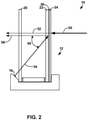
- FIG. 2 is a functional illustration of glazing structure 10 from FIG. 1 illustrating example light pathways during operation of the glazing structure.
- light from a light source 50 located on one side of glazing structure 10 may be directed toward glazing structure 10 when the layer of optically active material 26 is in a light scattering privacy state.
- a majority of the light reaching glazing structure 10 may be scattered and/or absorbed by optically active material 26, a portion of the light 52 may nevertheless pass through the material. This can potentially provide residual visibility through glazing structure 10 to an observer positioned on an opposite side of the structure.
- light emitting element 16 is configured to emit light that combines with the passing portion of light.
- light emitting element 16 is configured to direct light at the layer of optically active material 26 through first substrate 20 and second substrate 22.
- light emitting element 16 is configured to direct light 54 that passes through the number one surface of multiple-pane insulating glazing unit 12 provided by first substrate 20 followed by the number two surface of the unit. The light continues by passing through between-pane space 30 followed by the number three surface of the insulating glazing unit provided by second substrate 22 followed by the number four surface of the unit.
- this light 56 reflects off of the layer of optically active material 26, directing the light in reverse back through the number four surface of multiple-pane insulating glazing unit 12 followed by the number three surface, number two surface, and then number one surface.
- the light 56 reflecting off of the layer of optically active material 26 can combine with the light 52 passing through the layer of optically active material to mask residual visibility through glazing structure 10.
- a portion of light emitted by light emitting element 16 may reflect each time the light encounters a change in index of refraction.
- a portion of light may reflect at each of the number one, number two, number three, and number four surfaces of insulating glazing unit 12 with additional light being reflected by the reflective properties of optically active material 26.
- the amount of light reflected at each surface may vary, e.g., based on the materials of construction and the types of coatings, if any, provided on the substrates.
- a glazing structure with such example properties may be fabricated by using clear glass panes for first substrate 20 and second substrate 22, coating the number two surface of the insulating glazing unit with a low-emissivity coating, and using a liquid crystal material for optically active material 26.
- Light emitting element 16 can be located at any position on glazing structure 10 suitable to direct light through at least one of the structure substrates and at the layer of optically active material 26.
- light emitting element 16 is positioned on frame 14.
- light emitting element 16 is physically connected to first upward extending member 36 and positioned to direct light at the layer of optically active material 26 through first substrate 20 and second substrate 22.
- light emitting element 16 can be physically connected to second upward extending member 38 and positioned to direct light at the layer of optically active material 26 through third substrate 24.
- Light emitting element 16 can be physically connected to frame 14 using, e.g., adhesive, frictional engagement, and/or a mechanical fixation element. If desired, a recessed pocket can be created in frame 14 that is sized and shaped to hold light emitting element 16.
- Light emitting element 16 can be located on other portions of frame 14.
- light emitting element 16 can be physically connected to a portion of multiple-pane insulating glazing unit 12.
- light emitting element 16 is positioned on spacer 28 of insulating glazing unit 12 and configured to direct light at optically active material.
- FIG. 3 is an illustration of such an example configuration showing glazing structure 10 from FIG. 1 with light emitting element 16 carried by spacer 28 instead of frame 14.
- light emitting element 16 is located inside of between-pane space 30 and physically connected to spacer 28.
- Such an example positioning may be useful to isolate light emitting element 16 from external elements (e.g., water, debris) that can potential obscure or damage the light emitting element.
- the glazing structure can include any suitable number of light emitting elements.
- glazing structure 10 includes a single light emitting element 16 directed at the layer of optically active material 26.
- glazing structure 10 includes a plurality of light emitting elements 16 (e.g., two, three, four, or more) that are each directed at the layer of optically active material 26.
- all the light emitting elements can be positioned on one side of the glazing structure or different light emitting elements can be positioned on different sides of the glazing structure. For example, different light emitting elements can be positioned at different locations about the perimeter of the glazing structure.
- this may involve positioning light emitting elements on at least two different sizes of the structure (e.g., top and bottom, front and back), such as positioning light emitting elements on each of the four sides of the rectangular structure (e.g., top, bottom, right, left).
- positioning light emitting elements on at least two different sizes of the structure e.g., top and bottom, front and back
- positioning light emitting elements on each of the four sides of the rectangular structure e.g., top, bottom, right, left.
- arranging different light emitting elements at different locations about the perimeter of glazing structure 10 can help provide more uniform light emission on optically active material 26 than if all the light emitting elements are positioned at the same general location on the glazing structure.
- glazing structure 10 carries a light emitted element on each side of the structure, with adjacent light emitted elements being separated by a distance ranging from 0.5 feet to 2 feet, such as approximately 1 foot. Other separation distances and configurations are possible, however, and it should be appreciated that the disclosure is not limited in this respect.
- the light emitting elements may be positioned to direct light at a non-zero degree angle with respect to a planar face of the glazing structure.
- Such a configuration can allow the light emitting elements to be positioned out of a line of sight through glazing structure 10 when optically active material 26 is in a light transmissive state yet still direct light upon the material when in a light scattering privacy state.
- light emitting element 16 is illustrated as being located on frame 14 and orientated to direct light at an angle 60 measured relative to a normal axis passing through a planar face of multiple-pane insulating glazing unit 12 (e.g., an axis intersecting the planar face at a 90 degree angle).
- each light emitting element 16 is orientated such that its optical axis intersects a planar face of the insulating glazing unit at an angle 60 ranging from 15 degrees to 75 degrees, such as from 30 degrees to 70 degrees, or approximately 60 degrees.
- the optical axis may be the axis about which emitted light is centered for a particular light emitting element 16.
- Light emitting element 16 can be implemented using a variety of different light sources.
- each light emitting element carried by glazing structure 10 can be an incandescent light, a fluorescent light, a halogen light, a neon light, or yet other type of light source.
- each light emitting element carried by glazing structure 10 is a light emitting diode (LED). The use of light emitting diodes can provide a low power consuming source of light for masking glazing structure 10.
- the magnitude of light and the specific wavelengths at which each light emitting element emits can vary depending on the design of glazing structure 10. For example, the magnitude of light emitted by each light emitting element may be selected based on the size of glazing structure 10 and the number of light emitting elements carried by the structure. Similarly, the wavelengths at which each light emitting element emits may be selected based, for example, on characteristics of optically active material 26, such as the color of the material and reflectivity of the material at different wavelengths.
- each light emitting element is configured to emit at a single wavelength.
- each light emitting element may be a LED emitting green light at 532 nanometers (nm).
- each light emitting element is configured to emit light across a range of wavelengths.
- each light emitting element may be a LED emitting white light.
- Such a light emitting element can be implemented using a short wavelength LED with a phosphor coating.
- the one or more light emitting elements 16 carried by the structure are configured to be active (e.g., supplied with electricity and shining light) when the layer of optically active material 26 is in a privacy state.
- the one or more light emitting elements 16 are continuously active such that the elements emit light when the optically active material 16 is both in a light transmissive state and in a light scattering privacy state.
- the one or more light emitting elements 16 are configured to be inactive (e.g., not supplied with electricity, not shining light) when the layer of optically active material 26 is in a light transmissive state but active when the optically active material is placed in the light scattering privacy state.
- an electrical circuit may be closed, thereby supplying electricity to the one or more light emitting elements 16.
- engaging the switch to cause the layer of optically active material 26 to transition from the privacy state to the light transmissive state may open the electrical circuit, cutting electricity supply to the one or more light emitting elements 16.
- FIGS. 1-3 illustrate one example configuration of glazing structure 10 having a double-pane insulating glazing unit 12, it should be appreciated that other configurations are both possible and contemplated.
- glazing structure 10 may be implemented using a single glazing pane instead of a double-pane configuration as shown in FIGS. 1-3 .
- FIG. 4 is a partial side view illustration of another example glazing structure 100 that includes a single glazing pane and a light emitting element. Glazing structure 100 is the same as glazing structure 10 in FIGS. 1-3 except that first substrate 20 and between-pane space 30 have been omitted.
- Such a structure may be useful in applications where the thermal insulating benefits of a multiple-pane insulating glazing structure are not required, such as for temperate climates or when using the structure in a temperature controlled interior environment. It should be appreciated that terms such single pane and double pane are for purposes of discussion only and are not intended to exclude additional panes, such as a backing pane sandwiching optically active material 26 to the single pane or double pane structure.
- glazing structure 10 in FIGS. 1-3 may have four or more glazing panes and two or more between-pane spaces.
- glazing structure 10 may include a triple-pane insulating glazing unit instead of the double-pane insulating glazing unit shown in FIGS. 1-3 .
- FIG. 5 is a partial side view illustration of another example glazing structure 110 that includes a triple-pane insulating glazing unit.
- Glazing structure 110 is the same as glazing structure 10 in FIGS. 1-3 except multiple-pane insulating glazing unit 12 includes an additional substrate (designed 20A) separated from the previously-described first substrate (designated 20B) by an additional spacer (designated 28A) to define an additional between-pane space (designated 30A).
- the layer of optically active material 26 is positioned between substrate 22 and substrate 24, although in other examples, the optically active material can be positioned between substrate 20A and substrate 24 or substrate 20B and substrate 24.
- FIGS. 1-5 A variety of different privacy structures have been described with respect to FIGS. 1-5 .
- the example structures have been described in connection with one or more light emitting elements positioned to directed light at an optically active material that reflects a portion of the emitted light.
- the reflected light can screen visible light transmitted directly through the privacy structure, thereby masking residual visibility through the structure.
- a privacy structure can utilize a light emitting element that emits in a direction facing away from an optically active material (e.g., instead of or in addition to emitting toward the optically active material).
- one or more light emitting elements can be positioned to emit light in an outwardly facing direction away from the optically active material.
- the light emitted away from the optically active material can screen direct visible transmission through the optically active material when in a privacy state, thereby masking residual visibility through the structure.
- the reflected light may prevent the human observer's eyes from adjusting to the low level of light sensitivity necessary to resolve the low level of direct visible transmission still passing through glazing structure 10.
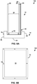
- FIG. 6A is a partial side view illustration of an example glazing structure 150 that includes at least one light emitting element 16 directing light away from an optically active material 26 carried by a multiple-pane insulating glazing unit 12.
- FIG. 6B is a front view of the example glazing structure 150 illustrating the structure carrying a plurality of light emitting elements.
- Glazing structure 150 is the same as glazing structure 10 in FIGS. 1-3 except that light emitting element 16 is positioned to direct light away from the layer of optically active material 26 rather than towards the layer of material.
- Such a structure may be useful in exterior wall applications where light emitting elements 16 is positioned facing an outdoor environment and to direct light toward that outdoor environment.
- the one or more light emitting elements 16 (which are illustrated as being a plurality of light emitting elements) of glazing structure 150 can emit light when the layer of optically active material 26 is in a privacy state.
- the light emitted by the elements can combine with residual light passing through the layer of optically active material 26. This can help optically mask residual visibility through the glazing structure.
- FIG. 7 is a partial side view illustration of another example glazing structure 160 that includes at least one light emitting element 162 directing light away from an optically active material 26 carried by a multiple-pane insulating glazing unit 12.
- Glazing structure 160 is the same as glazing structure 10 in FIGS. 1-3 except that light emitting element 162 is configured to direct light away from the layer of optically active material 26 (in addition, optionally, to directing light toward the layer of material).
- Light emitting element 162 is illustrated as being a light emitting coating, such as an organic light-emitting diode film, that is positioned in the number three surface of multiple-pane insulating glazing unit 12.
- the light emitting coating can be positioned on a different surface of the glazing unit, including any surface of the first substrate 20, the second substrate 22, and/or the third substrate 24.
- the light emitting coating of glazing structure 160 can emit light when the layer of optically active material 26 is in a privacy state.
- the light emitted by the coating can combine with residual light passing through the layer of optically active material 26. This can help optically mask residual visibility through the glazing structure.
- a privacy structure in accordance with the disclosure can be used in any desired applications including, without limitation, as a window or door installed in an external wall of a building, a panel or partition installed in an interior of a building, and as a window or panel in an automotive vehicle.
- one or more light emitting elements carried by the structure may be positioned to direct light in a direction from the exterior environment toward the interior environment. This can cause the light to impinge upon a optically active material in a privacy state and reflect back out toward the exterior environment, helping to mask residual visibility through the structure to an observer located outside of the building.
- the one or more light emitting elements may be positioned to direct light in a direction away from the interior environment and toward the exterior environment. This can cause the externally directed light to interfere with residual light passing through the structure, again helping to mask residual visibility through the structure to an observer located outside of the building.
Landscapes
- Physics & Mathematics (AREA)
- Nonlinear Science (AREA)
- General Physics & Mathematics (AREA)
- Optics & Photonics (AREA)
- Engineering & Computer Science (AREA)
- Structural Engineering (AREA)
- Chemical & Material Sciences (AREA)
- Crystallography & Structural Chemistry (AREA)
- Mathematical Physics (AREA)
- Architecture (AREA)
- Civil Engineering (AREA)
- Liquid Crystal (AREA)
Claims (16)
- Verglasungsstruktur (10; 100; 110), die Folgendes umfasst:ein erstes Substrat (22);ein zweites Substrat (24);eine Schicht aus elektrisch steuerbarem optisch aktivem Material (26), die zwischen dem ersten Substrat (22) und dem zweiten Substrat (24) angeordnet ist, wobei das elektrisch steuerbare optisch aktive Material (26) einen lichtdurchlässigen Zustand und einen Privatsphärenzustand aufweist; undmehrere lichtemittierende Elemente (16), die angeordnet sind, um Licht auf das erste Substrat (22), durch das jeweilige erste Substrat (22) und auf die Schicht aus elektrisch steuerbarem optisch aktivem Material (26) zu richten,wobei die mehreren lichtemittierenden Elemente (16) konfiguriert sind, um inaktiv zu sein, wenn sich das elektronisch steuerbare optisch aktive Material (26) in dem lichtdurchlässigen Zustand befindet, aber aktiviert wird, wenn das elektronisch steuerbare optisch aktive Material (26) in den Privatsphärenzustand versetzt wird, derart, dass Licht, das mittels mehrerer lichtemittierender Elemente (16) emittiert wird, von dem elektrisch steuerbaren optisch aktiven Material (26) reflektiert und Restsichtbarkeit durch das elektrisch steuerbare optisch aktive Material (26) maskiert wird, wenn es sich in dem Privatsphärenzustand befindet; unddadurch gekennzeichnet, dassmehrere lichtemittierende Elemente (16) derart angeordnet sind, dass optische Achsen, die die Achsen sind, um die das emittierte Licht für ein bestimmtes der lichtemittierenden Elemente (16) zentriert ist, eine ebene Oberfläche der Verglasungsstruktur (10; 100; 110) in einem Winkel in einem Bereich von 15 Grad bis 75 Grad hinsichtlich einer senkrechten Achse, die durch die ebene Fläche der Verglasungsstruktur (10; 100; 110) verläuft, schneiden, um Licht auf das erste Substrat (22) zu richten.
- Verglasungsstruktur (10; 100; 110) nach Anspruch 1, wobei das elektrisch steuerbare optisch aktive Material (26) ein Reflexionsvermögen aufweist, um wenigstens 5 Prozent des mittels der lichtemittierenden Elemente (16) emittierten Lichts zu reflektieren.
- Verglasungsstruktur nach Anspruch 1, wobei das elektrisch steuerbare optisch aktive Material (26) Flüssigkristalle umfasst.
- Verglasungsstruktur (10; 100; 110) nach Anspruch 1, wobei die lichtemittierenden Elemente (16) mehrere lichtemittierende Dioden (16) umfassen und wobei jede der mehreren lichtemittierenden Dioden (16) konfiguriert ist, um bei einer einzigen Wellenlänge zu emittieren.
- Verglasungsstruktur (10; 100; 110) nach Anspruch 1, wobei das optisch aktive Material (26), wenn es sich in dem lichtzerstreuenden Privatsphärenzustand befindet, eine direkte sichtbare Durchlässigkeit von über 0,1 Prozent aufweist.
- Mehrscheiben-Isolierverglasungseinheit, die die Verglasungsstruktur (10; 110) nach Anspruch 1 beinhaltet, wobei die Mehrscheiben-Isolierverglasungseinheit ferner ein drittes Substrat (20; 20B) und einen Abstandshalter (28; 28B), der das dritte Substrat (20; 20B) im Allgemeinen parallel zu und beabstandet von dem ersten Substrat (22) hält, um einen Zwischenscheibenraum (30; 30B) zu definieren, der mit einem isolierenden Gas gefüllt ist, umfasst.
- Mehrscheiben-Isolierverglasungseinheit nach Anspruch 6, wobei die mehreren lichtemittierenden Elemente (16) um den Umfang der Mehrscheiben-Isolierverglasungseinheit angeordnet sind.
- Mehrscheiben-Isolierverglasungseinheit nach Anspruch 6, die ferner einen Rahmen (14; 34), der um die Mehrscheiben-Isolierverglasungseinheit angeordnet ist, umfasst und wobei die lichtemittierenden Elemente (16) in einem Abstandshalter der Mehrscheiben-Isolierverglasungseinheit und/oder dem um die Mehrscheiben-Isolierverglasungseinheit angeordneten Rahmen (14; 34), angeordnet sind.
- Mehrscheiben-Isolierverglasungseinheit nach Anspruch 6, wobeidie Mehrscheiben-Isolierverglasungseinheit von einer externen Umgebung nach innen zu einer inneren Umgebung hin, eine Oberfläche Nummer eins, eine Oberfläche Nummer zwei, eine Oberfläche Nummer drei und eine Oberfläche Nummer vier definiert,wobei das dritte Substrat (20; 20B) angeordnet ist, um die Oberfläche Nummer eins und die Oberfläche Nummer zwei bereitzustellen, und das erste Substrat (22) angeordnet ist, um die Oberfläche Nummer drei und die Oberfläche Nummer vier bereitzustellen, unddie lichtemittierenden Elemente (16) angeordnet sind, um Licht durch die Oberfläche Nummer eins, gefolgt von den Oberflächen Nummer zwei, drei und vier der Mehrscheiben-Isolierverglasungseinheit, zu richten, wobei wenigstens ein Abschnitt dieser mittels des elektrisch steuerbaren optisch aktiven Materials (26) zurück durch die Oberfläche Nummer vier gefolgt von den Oberflächen Nummer drei, zwei und eins der Mehrscheiben-Isolierverglasungseinheit reflektiert wird.
- Mehrscheiben-Isolierverglasungseinheit nach einem der Ansprüche 6 bis 8, wobei die Mehrscheiben-Isolierverglasungseinheit ferner Folgendes umfasst:ein viertes Substrat (20A), das im Allgemeinen parallel zu dem ersten, zweiten und dritten Substrat (22, 24, 20B) ist; undeinen zweiten Abstandshalter, der zwischen dem vierten Substrat (20A) und dem dritten Substrat (20B) angeordnet (28A) ist, um einen zweiten Zwischenscheibenraum (30A) zu definieren.
- Mehrscheiben-Isolierverglasungseinheit nach Anspruch 10, die ferner einen Rahmen, der um die Mehrscheiben-Isolierverglasungseinheit angeordnet (34) ist, umfasst und wobei die lichtemittierenden Elemente (16) in einem Abstandshalter (28A, 28B) und/oder dem um die Mehrscheiben-Isolierverglasungseinheit angeordneten Rahmen (34) angeordnet sind.
- Mehrscheiben-Isolierverglasungseinheit nach Anspruch 10, wobeidie Mehrscheiben-Isolierverglasungseinheit von einer externen Umgebung nach innen zu einer inneren Umgebung hin, eine Oberfläche Nummer eins, eine Oberfläche Nummer zwei, eine Oberfläche Nummer drei und eine Oberfläche Nummer vier definiert,das vierte Substrat (20A) angeordnet ist, um die Oberfläche Nummer eins und die Oberfläche Nummer zwei bereitzustellen, und das erste Substrat (22) angeordnet ist, um die Oberfläche Nummer drei und die Oberfläche Nummer vier bereitzustellen, unddie lichtemittierenden Elemente (16) angeordnet sind, um Licht durch die Oberfläche Nummer eins, gefolgt von den Oberflächen Nummer zwei, drei und vier der Mehrscheiben-Isolierverglasungseinheit, zu richten, wobei wenigstens ein Abschnitt dieser mittels des elektrisch steuerbaren optisch aktiven Materials (26) zurück durch die Oberfläche Nummer vier gefolgt von den Oberflächen Nummer drei, zwei und eins der Mehrscheiben-Isolierverglasungseinheit reflektiert wird.
- Verfahren, um die Restsichtbarkeit durch eine Verglasungsstruktur nach Anspruch 1 zu maskieren, das Folgendes umfasst:Steuern des elektronisch steuerbaren optisch aktiven Materials (26), um das elektronisch steuerbare optisch aktive Material von einem lichtdurchlässigen Zustand in einen Privatsphärenzustand zu überführen;
undSteuern von Licht von den lichtemittierenden Elementen (16), derart, dass Licht durch das erste Substrat (22) auf das elektronisch steuerbare optisch aktive Material (26) in dem Privatsphärenzustand gerichtet wird, wobei dadurch bewirkt wird, dass wenigstens ein Abschnitt des Lichts von dem elektronisch steuerbaren optisch aktiven Material (26) reflektiert und Restsichtbarkeit durch das elektronisch steuerbare optisch aktive Material (26) maskiert wird, wobei das Richten von Licht durch das erste Substrat (22) das Richten von Licht in einem Winkel in dem Bereich von 15 Grad bis 75 Grad hinsichtlich einer senkrechten Achse, die durch eine ebene Fläche der Verglasungsstruktur (10; 100; 110) verläuft, umfasst. - Verfahren nach Anspruch 13, wobei das optisch aktive Material (26) Flüssigkristalle umfasst und das Steuern des optisch aktiven Materials (26) ein Anlegen von elektrischem Strom an die Flüssigkristalle und ein Beenden einer Zufuhr von elektrischem Strom an die Flüssigkristalle umfasst.
- Verfahren nach Anspruch 13, um die Restsichtbarkeit durch eine Mehrscheiben-Isolierverglasungseinheit nach Anspruch 6 zu maskieren, wobei das Richten von Licht durch das erste Substrat (22) das Richten von Licht durch das dritte transparente Substrat (20; 20B), das erste Substrat (22) und den Zwischenscheibenraum, der mit Isoliergas gefüllt (30; 30B) ist, das das dritte Substrat (20; 20B) von dem ersten Substrat (22) trennt, umfasst.
- Verfahren nach Anspruch 13, das ferner Folgendes umfasst:Steuern des elektrisch steuerbaren optisch aktiven Materials (26), um das elektrisch steuerbare optisch aktive Material von dem Privatsphärenzustand in den lichtdurchlässigen Zustand zu überführen; undDeaktivieren der lichtemittierenden Elemente (16), die Licht durch das erste Substrat (22) auf das elektrisch steuerbare optisch aktive Material (26) richten.
Applications Claiming Priority (2)
| Application Number | Priority Date | Filing Date | Title |
|---|---|---|---|
| US201461971952P | 2014-03-28 | 2014-03-28 | |
| PCT/US2015/022503 WO2015148675A1 (en) | 2014-03-28 | 2015-03-25 | Light masked smart glazing |
Publications (2)
| Publication Number | Publication Date |
|---|---|
| EP3122983A1 EP3122983A1 (de) | 2017-02-01 |
| EP3122983B1 true EP3122983B1 (de) | 2022-01-26 |
Family
ID=52823851
Family Applications (1)
| Application Number | Title | Priority Date | Filing Date |
|---|---|---|---|
| EP15715593.8A Active EP3122983B1 (de) | 2014-03-28 | 2015-03-25 | Intelligente verglasung mit lichtabschirmung |
Country Status (3)
| Country | Link |
|---|---|
| US (1) | US9904136B2 (de) |
| EP (1) | EP3122983B1 (de) |
| WO (1) | WO2015148675A1 (de) |
Families Citing this family (17)
| Publication number | Priority date | Publication date | Assignee | Title |
|---|---|---|---|---|
| WO2014171470A1 (ja) * | 2013-04-19 | 2014-10-23 | 本田技研工業株式会社 | 調光パネル構造体 |
| CN108139615A (zh) * | 2015-10-16 | 2018-06-08 | 新加坡科技研究局 | 基于发光二极管和可切换玻璃的单向视觉私密窗户 |
| GB201614208D0 (en) * | 2016-08-19 | 2016-10-05 | Pilkington Group Ltd | Switchable glazing unit |
| KR102771738B1 (ko) | 2016-11-09 | 2025-02-26 | 코닝 인코포레이티드 | 감소된 보우를 갖는 조도조절이 가능한 창유리 및 이를 포함하는 절연 글레이징 유닛 |
| KR102780253B1 (ko) | 2017-02-08 | 2025-03-11 | 카디날 아이지 컴퍼니 | 필름-유리 전환 가능한 창유리 |
| WO2018195458A1 (en) | 2017-04-20 | 2018-10-25 | Cardinal Ig Company | High performance privacy glazing structures |
| WO2019014613A1 (en) | 2017-07-13 | 2019-01-17 | Cardinal Ig Company | ELECTRICAL CONNECTION CONFIGURATIONS OF OPAQUE GLAZING STRUCTURES |
| US11360364B2 (en) * | 2017-11-06 | 2022-06-14 | Cardinal Ig Company | Privacy glazing system with discrete electrical driver |
| EP3790735A1 (de) | 2018-05-09 | 2021-03-17 | Cardinal Ig Company | Elektrisch steuerbare sichtschutzverglasung mit energierückgewinnungstreiber |
| US10968684B2 (en) | 2018-08-17 | 2021-04-06 | Cardinal Ig Company | Privacy glazing structure with asymetrical pane offsets for electrical connection configurations |
| US11474385B1 (en) | 2018-12-02 | 2022-10-18 | Cardinal Ig Company | Electrically controllable privacy glazing with ultralow power consumption comprising a liquid crystal material having a light transmittance that varies in response to application of an electric field |
| CN113518712A (zh) | 2019-02-08 | 2021-10-19 | 卡迪纳尔Ig公司 | 用于隐私玻璃窗的低功率驱动器 |
| US11175523B2 (en) | 2019-04-29 | 2021-11-16 | Cardinal Ig Company | Staggered driving electrical control of a plurality of electrically controllable privacy glazing structures |
| KR102809744B1 (ko) * | 2019-04-29 | 2025-05-16 | 카디날 아이지 컴퍼니 | 하나 이상의 전기적으로 제어 가능한 사생활 보호 유리 구조에 대한 누설 전류 감지 및 제어 |
| CN114072726B (zh) | 2019-04-29 | 2024-05-31 | 卡迪纳尔Ig公司 | 用于操作一个或多个电可控隐私玻璃窗结构的系统和方法 |
| DE102019120975A1 (de) * | 2019-08-02 | 2021-02-04 | OPAK Aviation GmbH | Mehrschichtige Verscheibung |
| IL274590B2 (en) * | 2020-05-11 | 2024-07-01 | Polaris Solutions Ltd | System, method and computerized storage device for controlling the observed temperature of one or more panels |
Family Cites Families (12)
| Publication number | Priority date | Publication date | Assignee | Title |
|---|---|---|---|---|
| US3280701A (en) | 1961-09-05 | 1966-10-25 | Donnelly Mirrors Inc | Optically variable one-way mirror |
| US6671008B1 (en) | 1991-11-27 | 2003-12-30 | Reveo, Inc. | Electro-optical glazing structures having scattering and transparent modes of operation and methods and apparatus for making the same |
| DE29506194U1 (de) * | 1995-04-10 | 1995-06-08 | Wolters, Paolo, 12555 Berlin | Fensterelement zur Abschirmung und Erhellung von Innenräumen |
| US6239898B1 (en) | 1998-11-30 | 2001-05-29 | Gentex Corporation | Electrochromic structures |
| DE10205405A1 (de) * | 2002-02-09 | 2003-08-21 | Thomas Emde | Fensterelement |
| DE10322561B4 (de) | 2003-05-20 | 2011-06-22 | Isolar Isolierglaserzeugung Ges.M.B.H. | Isolierglaselement mit Lichtrahmen |
| US20050068629A1 (en) | 2003-09-26 | 2005-03-31 | Primal Fernando | Adjustably opaque window |
| US7525604B2 (en) | 2005-03-15 | 2009-04-28 | Naxellent, Llc | Windows with electrically controllable transmission and reflection |
| US20080158448A1 (en) | 2005-12-09 | 2008-07-03 | Primal Fernando | Adjustably Opaque Window |
| US20070218217A1 (en) | 2006-03-17 | 2007-09-20 | Primal Fernando | Adjustably opaque film for substantially smooth surface |
| US7940457B2 (en) | 2008-05-30 | 2011-05-10 | The Board Of Trustees Of The University Of Illinois | Energy-efficient optoelectronic smart window |
| CN102449678A (zh) * | 2009-05-28 | 2012-05-09 | 皇家飞利浦电子股份有限公司 | 透明发光窗口 |
-
2015
- 2015-03-25 US US14/668,636 patent/US9904136B2/en active Active
- 2015-03-25 WO PCT/US2015/022503 patent/WO2015148675A1/en not_active Ceased
- 2015-03-25 EP EP15715593.8A patent/EP3122983B1/de active Active
Also Published As
| Publication number | Publication date |
|---|---|
| US20150277165A1 (en) | 2015-10-01 |
| EP3122983A1 (de) | 2017-02-01 |
| US9904136B2 (en) | 2018-02-27 |
| WO2015148675A1 (en) | 2015-10-01 |
Similar Documents
| Publication | Publication Date | Title |
|---|---|---|
| US9904136B2 (en) | Light masked smart glazing | |
| US12253783B2 (en) | High performance privacy glazing structures | |
| US20230296952A1 (en) | Privacy glazing system with discrete electrical driver | |
| US12000203B2 (en) | Privacy glazing structure with asymetrical pane offsets for electrical connection configurations | |
| KR101480948B1 (ko) | 스마트 윈도우 | |
| US9051771B2 (en) | Sun protection device with angle-selective transmission properties | |
| EA033599B1 (ru) | Стеклянная крыша транспортного средства | |
| KR20150067311A (ko) | 스위칭가능한 광학 특성을 갖는 글레이징 | |
| US20140047783A1 (en) | Window with modifiable transparency | |
| CN206503500U (zh) | 电致变色的夹层玻璃、窗户及幕墙显示系统 | |
| CA3069532A1 (en) | Electrical connection configurations for privacy glazing structures | |
| KR20220163025A (ko) | 옥외용 디스플레이 장치 | |
| KR20240107274A (ko) | 가변 모듈이 구비된 스마트 윈도우 | |
| US20240313484A1 (en) | Electrical connector with shunt for privacy glazing structure | |
| WO2016009597A1 (ja) | 面状光学素子、照明装置及び建材 | |
| WO2016009589A1 (ja) | 面状光学素子、照明装置及び建材 | |
| KR20130003833U (ko) | 조광평면구조 |
Legal Events
| Date | Code | Title | Description |
|---|---|---|---|
| STAA | Information on the status of an ep patent application or granted ep patent |
Free format text: STATUS: THE INTERNATIONAL PUBLICATION HAS BEEN MADE |
|
| PUAI | Public reference made under article 153(3) epc to a published international application that has entered the european phase |
Free format text: ORIGINAL CODE: 0009012 |
|
| STAA | Information on the status of an ep patent application or granted ep patent |
Free format text: STATUS: REQUEST FOR EXAMINATION WAS MADE |
|
| 17P | Request for examination filed |
Effective date: 20160928 |
|
| AK | Designated contracting states |
Kind code of ref document: A1 Designated state(s): AL AT BE BG CH CY CZ DE DK EE ES FI FR GB GR HR HU IE IS IT LI LT LU LV MC MK MT NL NO PL PT RO RS SE SI SK SM TR |
|
| AX | Request for extension of the european patent |
Extension state: BA ME |
|
| DAV | Request for validation of the european patent (deleted) | ||
| DAX | Request for extension of the european patent (deleted) | ||
| STAA | Information on the status of an ep patent application or granted ep patent |
Free format text: STATUS: EXAMINATION IS IN PROGRESS |
|
| 17Q | First examination report despatched |
Effective date: 20171019 |
|
| GRAP | Despatch of communication of intention to grant a patent |
Free format text: ORIGINAL CODE: EPIDOSNIGR1 |
|
| STAA | Information on the status of an ep patent application or granted ep patent |
Free format text: STATUS: GRANT OF PATENT IS INTENDED |
|
| INTG | Intention to grant announced |
Effective date: 20210827 |
|
| GRAS | Grant fee paid |
Free format text: ORIGINAL CODE: EPIDOSNIGR3 |
|
| GRAA | (expected) grant |
Free format text: ORIGINAL CODE: 0009210 |
|
| STAA | Information on the status of an ep patent application or granted ep patent |
Free format text: STATUS: THE PATENT HAS BEEN GRANTED |
|
| AK | Designated contracting states |
Kind code of ref document: B1 Designated state(s): AL AT BE BG CH CY CZ DE DK EE ES FI FR GB GR HR HU IE IS IT LI LT LU LV MC MK MT NL NO PL PT RO RS SE SI SK SM TR |
|
| REG | Reference to a national code |
Ref country code: GB Ref legal event code: FG4D |
|
| REG | Reference to a national code |
Ref country code: CH Ref legal event code: EP |
|
| REG | Reference to a national code |
Ref country code: AT Ref legal event code: REF Ref document number: 1465429 Country of ref document: AT Kind code of ref document: T Effective date: 20220215 |
|
| REG | Reference to a national code |
Ref country code: IE Ref legal event code: FG4D |
|
| REG | Reference to a national code |
Ref country code: DE Ref legal event code: R096 Ref document number: 602015076629 Country of ref document: DE |
|
| REG | Reference to a national code |
Ref country code: LT Ref legal event code: MG9D |
|
| REG | Reference to a national code |
Ref country code: NL Ref legal event code: MP Effective date: 20220126 |
|
| REG | Reference to a national code |
Ref country code: AT Ref legal event code: MK05 Ref document number: 1465429 Country of ref document: AT Kind code of ref document: T Effective date: 20220126 |
|
| PG25 | Lapsed in a contracting state [announced via postgrant information from national office to epo] |
Ref country code: NL Free format text: LAPSE BECAUSE OF FAILURE TO SUBMIT A TRANSLATION OF THE DESCRIPTION OR TO PAY THE FEE WITHIN THE PRESCRIBED TIME-LIMIT Effective date: 20220126 |
|
| PG25 | Lapsed in a contracting state [announced via postgrant information from national office to epo] |
Ref country code: SE Free format text: LAPSE BECAUSE OF FAILURE TO SUBMIT A TRANSLATION OF THE DESCRIPTION OR TO PAY THE FEE WITHIN THE PRESCRIBED TIME-LIMIT Effective date: 20220126 Ref country code: RS Free format text: LAPSE BECAUSE OF FAILURE TO SUBMIT A TRANSLATION OF THE DESCRIPTION OR TO PAY THE FEE WITHIN THE PRESCRIBED TIME-LIMIT Effective date: 20220126 Ref country code: PT Free format text: LAPSE BECAUSE OF FAILURE TO SUBMIT A TRANSLATION OF THE DESCRIPTION OR TO PAY THE FEE WITHIN THE PRESCRIBED TIME-LIMIT Effective date: 20220526 Ref country code: NO Free format text: LAPSE BECAUSE OF FAILURE TO SUBMIT A TRANSLATION OF THE DESCRIPTION OR TO PAY THE FEE WITHIN THE PRESCRIBED TIME-LIMIT Effective date: 20220426 Ref country code: LT Free format text: LAPSE BECAUSE OF FAILURE TO SUBMIT A TRANSLATION OF THE DESCRIPTION OR TO PAY THE FEE WITHIN THE PRESCRIBED TIME-LIMIT Effective date: 20220126 Ref country code: HR Free format text: LAPSE BECAUSE OF FAILURE TO SUBMIT A TRANSLATION OF THE DESCRIPTION OR TO PAY THE FEE WITHIN THE PRESCRIBED TIME-LIMIT Effective date: 20220126 Ref country code: ES Free format text: LAPSE BECAUSE OF FAILURE TO SUBMIT A TRANSLATION OF THE DESCRIPTION OR TO PAY THE FEE WITHIN THE PRESCRIBED TIME-LIMIT Effective date: 20220126 Ref country code: BG Free format text: LAPSE BECAUSE OF FAILURE TO SUBMIT A TRANSLATION OF THE DESCRIPTION OR TO PAY THE FEE WITHIN THE PRESCRIBED TIME-LIMIT Effective date: 20220426 |
|
| PG25 | Lapsed in a contracting state [announced via postgrant information from national office to epo] |
Ref country code: PL Free format text: LAPSE BECAUSE OF FAILURE TO SUBMIT A TRANSLATION OF THE DESCRIPTION OR TO PAY THE FEE WITHIN THE PRESCRIBED TIME-LIMIT Effective date: 20220126 Ref country code: LV Free format text: LAPSE BECAUSE OF FAILURE TO SUBMIT A TRANSLATION OF THE DESCRIPTION OR TO PAY THE FEE WITHIN THE PRESCRIBED TIME-LIMIT Effective date: 20220126 Ref country code: GR Free format text: LAPSE BECAUSE OF FAILURE TO SUBMIT A TRANSLATION OF THE DESCRIPTION OR TO PAY THE FEE WITHIN THE PRESCRIBED TIME-LIMIT Effective date: 20220427 Ref country code: FI Free format text: LAPSE BECAUSE OF FAILURE TO SUBMIT A TRANSLATION OF THE DESCRIPTION OR TO PAY THE FEE WITHIN THE PRESCRIBED TIME-LIMIT Effective date: 20220126 Ref country code: AT Free format text: LAPSE BECAUSE OF FAILURE TO SUBMIT A TRANSLATION OF THE DESCRIPTION OR TO PAY THE FEE WITHIN THE PRESCRIBED TIME-LIMIT Effective date: 20220126 |
|
| PG25 | Lapsed in a contracting state [announced via postgrant information from national office to epo] |
Ref country code: IS Free format text: LAPSE BECAUSE OF FAILURE TO SUBMIT A TRANSLATION OF THE DESCRIPTION OR TO PAY THE FEE WITHIN THE PRESCRIBED TIME-LIMIT Effective date: 20220526 |
|
| REG | Reference to a national code |
Ref country code: DE Ref legal event code: R097 Ref document number: 602015076629 Country of ref document: DE |
|
| PG25 | Lapsed in a contracting state [announced via postgrant information from national office to epo] |
Ref country code: SM Free format text: LAPSE BECAUSE OF FAILURE TO SUBMIT A TRANSLATION OF THE DESCRIPTION OR TO PAY THE FEE WITHIN THE PRESCRIBED TIME-LIMIT Effective date: 20220126 Ref country code: SK Free format text: LAPSE BECAUSE OF FAILURE TO SUBMIT A TRANSLATION OF THE DESCRIPTION OR TO PAY THE FEE WITHIN THE PRESCRIBED TIME-LIMIT Effective date: 20220126 Ref country code: RO Free format text: LAPSE BECAUSE OF FAILURE TO SUBMIT A TRANSLATION OF THE DESCRIPTION OR TO PAY THE FEE WITHIN THE PRESCRIBED TIME-LIMIT Effective date: 20220126 Ref country code: MC Free format text: LAPSE BECAUSE OF FAILURE TO SUBMIT A TRANSLATION OF THE DESCRIPTION OR TO PAY THE FEE WITHIN THE PRESCRIBED TIME-LIMIT Effective date: 20220126 Ref country code: EE Free format text: LAPSE BECAUSE OF FAILURE TO SUBMIT A TRANSLATION OF THE DESCRIPTION OR TO PAY THE FEE WITHIN THE PRESCRIBED TIME-LIMIT Effective date: 20220126 Ref country code: DK Free format text: LAPSE BECAUSE OF FAILURE TO SUBMIT A TRANSLATION OF THE DESCRIPTION OR TO PAY THE FEE WITHIN THE PRESCRIBED TIME-LIMIT Effective date: 20220126 Ref country code: CZ Free format text: LAPSE BECAUSE OF FAILURE TO SUBMIT A TRANSLATION OF THE DESCRIPTION OR TO PAY THE FEE WITHIN THE PRESCRIBED TIME-LIMIT Effective date: 20220126 |
|
| REG | Reference to a national code |
Ref country code: CH Ref legal event code: PL |
|
| PG25 | Lapsed in a contracting state [announced via postgrant information from national office to epo] |
Ref country code: AL Free format text: LAPSE BECAUSE OF FAILURE TO SUBMIT A TRANSLATION OF THE DESCRIPTION OR TO PAY THE FEE WITHIN THE PRESCRIBED TIME-LIMIT Effective date: 20220126 |
|
| PLBE | No opposition filed within time limit |
Free format text: ORIGINAL CODE: 0009261 |
|
| STAA | Information on the status of an ep patent application or granted ep patent |
Free format text: STATUS: NO OPPOSITION FILED WITHIN TIME LIMIT |
|
| REG | Reference to a national code |
Ref country code: BE Ref legal event code: MM Effective date: 20220331 |
|
| 26N | No opposition filed |
Effective date: 20221027 |
|
| PG25 | Lapsed in a contracting state [announced via postgrant information from national office to epo] |
Ref country code: LU Free format text: LAPSE BECAUSE OF NON-PAYMENT OF DUE FEES Effective date: 20220325 Ref country code: LI Free format text: LAPSE BECAUSE OF NON-PAYMENT OF DUE FEES Effective date: 20220331 Ref country code: IE Free format text: LAPSE BECAUSE OF NON-PAYMENT OF DUE FEES Effective date: 20220325 Ref country code: CH Free format text: LAPSE BECAUSE OF NON-PAYMENT OF DUE FEES Effective date: 20220331 |
|
| PG25 | Lapsed in a contracting state [announced via postgrant information from national office to epo] |
Ref country code: SI Free format text: LAPSE BECAUSE OF FAILURE TO SUBMIT A TRANSLATION OF THE DESCRIPTION OR TO PAY THE FEE WITHIN THE PRESCRIBED TIME-LIMIT Effective date: 20220126 Ref country code: BE Free format text: LAPSE BECAUSE OF NON-PAYMENT OF DUE FEES Effective date: 20220331 |
|
| PGFP | Annual fee paid to national office [announced via postgrant information from national office to epo] |
Ref country code: FR Payment date: 20230327 Year of fee payment: 9 |
|
| PGFP | Annual fee paid to national office [announced via postgrant information from national office to epo] |
Ref country code: GB Payment date: 20230327 Year of fee payment: 9 |
|
| P01 | Opt-out of the competence of the unified patent court (upc) registered |
Effective date: 20230524 |
|
| PG25 | Lapsed in a contracting state [announced via postgrant information from national office to epo] |
Ref country code: IT Free format text: LAPSE BECAUSE OF FAILURE TO SUBMIT A TRANSLATION OF THE DESCRIPTION OR TO PAY THE FEE WITHIN THE PRESCRIBED TIME-LIMIT Effective date: 20220126 |
|
| PG25 | Lapsed in a contracting state [announced via postgrant information from national office to epo] |
Ref country code: HU Free format text: LAPSE BECAUSE OF FAILURE TO SUBMIT A TRANSLATION OF THE DESCRIPTION OR TO PAY THE FEE WITHIN THE PRESCRIBED TIME-LIMIT; INVALID AB INITIO Effective date: 20150325 |
|
| PG25 | Lapsed in a contracting state [announced via postgrant information from national office to epo] |
Ref country code: MK Free format text: LAPSE BECAUSE OF FAILURE TO SUBMIT A TRANSLATION OF THE DESCRIPTION OR TO PAY THE FEE WITHIN THE PRESCRIBED TIME-LIMIT Effective date: 20220126 Ref country code: CY Free format text: LAPSE BECAUSE OF FAILURE TO SUBMIT A TRANSLATION OF THE DESCRIPTION OR TO PAY THE FEE WITHIN THE PRESCRIBED TIME-LIMIT Effective date: 20220126 |
|
| PG25 | Lapsed in a contracting state [announced via postgrant information from national office to epo] |
Ref country code: TR Free format text: LAPSE BECAUSE OF FAILURE TO SUBMIT A TRANSLATION OF THE DESCRIPTION OR TO PAY THE FEE WITHIN THE PRESCRIBED TIME-LIMIT Effective date: 20220126 |
|
| PG25 | Lapsed in a contracting state [announced via postgrant information from national office to epo] |
Ref country code: MT Free format text: LAPSE BECAUSE OF FAILURE TO SUBMIT A TRANSLATION OF THE DESCRIPTION OR TO PAY THE FEE WITHIN THE PRESCRIBED TIME-LIMIT Effective date: 20220126 |
|
| GBPC | Gb: european patent ceased through non-payment of renewal fee |
Effective date: 20240325 |
|
| PG25 | Lapsed in a contracting state [announced via postgrant information from national office to epo] |
Ref country code: GB Free format text: LAPSE BECAUSE OF NON-PAYMENT OF DUE FEES Effective date: 20240325 |
|
| PG25 | Lapsed in a contracting state [announced via postgrant information from national office to epo] |
Ref country code: FR Free format text: LAPSE BECAUSE OF NON-PAYMENT OF DUE FEES Effective date: 20240331 |
|
| PG25 | Lapsed in a contracting state [announced via postgrant information from national office to epo] |
Ref country code: GB Free format text: LAPSE BECAUSE OF NON-PAYMENT OF DUE FEES Effective date: 20240325 Ref country code: FR Free format text: LAPSE BECAUSE OF NON-PAYMENT OF DUE FEES Effective date: 20240331 |
|
| PGFP | Annual fee paid to national office [announced via postgrant information from national office to epo] |
Ref country code: DE Payment date: 20260327 Year of fee payment: 12 |