EP3122990B1 - Système et procédé d'exploitation de gaz produit dans des formations d'hydrate de gaz - Google Patents
Système et procédé d'exploitation de gaz produit dans des formations d'hydrate de gaz Download PDFInfo
- Publication number
- EP3122990B1 EP3122990B1 EP16710031.2A EP16710031A EP3122990B1 EP 3122990 B1 EP3122990 B1 EP 3122990B1 EP 16710031 A EP16710031 A EP 16710031A EP 3122990 B1 EP3122990 B1 EP 3122990B1
- Authority
- EP
- European Patent Office
- Prior art keywords
- gas
- water
- drilling
- formation
- production tubing
- Prior art date
- Legal status (The legal status is an assumption and is not a legal conclusion. Google has not performed a legal analysis and makes no representation as to the accuracy of the status listed.)
- Active
Links
Images


Classifications
-
- E—FIXED CONSTRUCTIONS
- E21—EARTH OR ROCK DRILLING; MINING
- E21B—EARTH OR ROCK DRILLING; OBTAINING OIL, GAS, WATER, SOLUBLE OR MELTABLE MATERIALS OR A SLURRY OF MINERALS FROM WELLS
- E21B43/00—Methods or apparatus for obtaining oil, gas, water, soluble or meltable materials or a slurry of minerals from wells
- E21B43/34—Arrangements for separating materials produced by the well
- E21B43/38—Arrangements for separating materials produced by the well in the well
-
- E—FIXED CONSTRUCTIONS
- E21—EARTH OR ROCK DRILLING; MINING
- E21B—EARTH OR ROCK DRILLING; OBTAINING OIL, GAS, WATER, SOLUBLE OR MELTABLE MATERIALS OR A SLURRY OF MINERALS FROM WELLS
- E21B29/00—Cutting or destroying pipes, packers, plugs or wire lines, located in boreholes or wells, e.g. cutting of damaged pipes, of windows; Deforming of pipes in boreholes or wells; Reconditioning of well casings while in the ground
- E21B29/06—Cutting windows, e.g. directional window cutters for whipstock operations
-
- E—FIXED CONSTRUCTIONS
- E21—EARTH OR ROCK DRILLING; MINING
- E21B—EARTH OR ROCK DRILLING; OBTAINING OIL, GAS, WATER, SOLUBLE OR MELTABLE MATERIALS OR A SLURRY OF MINERALS FROM WELLS
- E21B41/00—Equipment or details not covered by groups E21B15/00 - E21B40/00
- E21B41/0099—Equipment or details not covered by groups E21B15/00 - E21B40/00 specially adapted for drilling for or production of natural hydrate or clathrate gas reservoirs; Drilling through or monitoring of formations containing gas hydrates or clathrates
-
- E—FIXED CONSTRUCTIONS
- E21—EARTH OR ROCK DRILLING; MINING
- E21B—EARTH OR ROCK DRILLING; OBTAINING OIL, GAS, WATER, SOLUBLE OR MELTABLE MATERIALS OR A SLURRY OF MINERALS FROM WELLS
- E21B43/00—Methods or apparatus for obtaining oil, gas, water, soluble or meltable materials or a slurry of minerals from wells
- E21B43/02—Subsoil filtering
- E21B43/08—Screens or liners
- E21B43/086—Screens with preformed openings, e.g. slotted liners
-
- E—FIXED CONSTRUCTIONS
- E21—EARTH OR ROCK DRILLING; MINING
- E21B—EARTH OR ROCK DRILLING; OBTAINING OIL, GAS, WATER, SOLUBLE OR MELTABLE MATERIALS OR A SLURRY OF MINERALS FROM WELLS
- E21B43/00—Methods or apparatus for obtaining oil, gas, water, soluble or meltable materials or a slurry of minerals from wells
- E21B43/16—Enhanced recovery methods for obtaining hydrocarbons
-
- E—FIXED CONSTRUCTIONS
- E21—EARTH OR ROCK DRILLING; MINING
- E21B—EARTH OR ROCK DRILLING; OBTAINING OIL, GAS, WATER, SOLUBLE OR MELTABLE MATERIALS OR A SLURRY OF MINERALS FROM WELLS
- E21B43/00—Methods or apparatus for obtaining oil, gas, water, soluble or meltable materials or a slurry of minerals from wells
- E21B43/16—Enhanced recovery methods for obtaining hydrocarbons
- E21B43/18—Repressuring or vacuum methods
-
- E—FIXED CONSTRUCTIONS
- E21—EARTH OR ROCK DRILLING; MINING
- E21B—EARTH OR ROCK DRILLING; OBTAINING OIL, GAS, WATER, SOLUBLE OR MELTABLE MATERIALS OR A SLURRY OF MINERALS FROM WELLS
- E21B43/00—Methods or apparatus for obtaining oil, gas, water, soluble or meltable materials or a slurry of minerals from wells
- E21B43/16—Enhanced recovery methods for obtaining hydrocarbons
- E21B43/24—Enhanced recovery methods for obtaining hydrocarbons using heat, e.g. steam injection
-
- E—FIXED CONSTRUCTIONS
- E21—EARTH OR ROCK DRILLING; MINING
- E21B—EARTH OR ROCK DRILLING; OBTAINING OIL, GAS, WATER, SOLUBLE OR MELTABLE MATERIALS OR A SLURRY OF MINERALS FROM WELLS
- E21B43/00—Methods or apparatus for obtaining oil, gas, water, soluble or meltable materials or a slurry of minerals from wells
- E21B43/28—Dissolving minerals other than hydrocarbons, e.g. by an alkaline or acid leaching agent
-
- E—FIXED CONSTRUCTIONS
- E21—EARTH OR ROCK DRILLING; MINING
- E21B—EARTH OR ROCK DRILLING; OBTAINING OIL, GAS, WATER, SOLUBLE OR MELTABLE MATERIALS OR A SLURRY OF MINERALS FROM WELLS
- E21B43/00—Methods or apparatus for obtaining oil, gas, water, soluble or meltable materials or a slurry of minerals from wells
- E21B43/30—Specific pattern of wells, e.g. optimising the spacing of wells
-
- E—FIXED CONSTRUCTIONS
- E21—EARTH OR ROCK DRILLING; MINING
- E21B—EARTH OR ROCK DRILLING; OBTAINING OIL, GAS, WATER, SOLUBLE OR MELTABLE MATERIALS OR A SLURRY OF MINERALS FROM WELLS
- E21B7/00—Special methods or apparatus for drilling
- E21B7/04—Directional drilling
-
- E—FIXED CONSTRUCTIONS
- E21—EARTH OR ROCK DRILLING; MINING
- E21B—EARTH OR ROCK DRILLING; OBTAINING OIL, GAS, WATER, SOLUBLE OR MELTABLE MATERIALS OR A SLURRY OF MINERALS FROM WELLS
- E21B47/00—Survey of boreholes or wells
- E21B47/09—Locating or determining the position of objects in boreholes or wells, e.g. the position of an extending arm; Identifying the free or blocked portions of pipes
-
- E—FIXED CONSTRUCTIONS
- E21—EARTH OR ROCK DRILLING; MINING
- E21B—EARTH OR ROCK DRILLING; OBTAINING OIL, GAS, WATER, SOLUBLE OR MELTABLE MATERIALS OR A SLURRY OF MINERALS FROM WELLS
- E21B7/00—Special methods or apparatus for drilling
- E21B7/18—Drilling by liquid or gas jets, with or without entrained pellets
Definitions
- the invention is related to a method developed to obtain gas from gas hydrate formations.
- a production tubing is drilled in the form of strips beforehand wherein the openings drilled in the form of strips are plugged and sealed with pressure resistant plugs.
- Said production tubing is used in a system which is developed to obtain gas from gas hydrate formations.
- Said production tubing can also can be used in the production of petroleum, petroleum liquids, gas, shale gas, and all kinds of hydrocarbons.
- a gas hydrate is a crystalline solid that consists of a gas molecule surrounded by water molecules.
- Gas hydrates may be formed of a number of gases with a proper molecular size. These include carbon dioxide, hydrogen sulfide and several low carbon number hydrocarbons, including methane. Gas hydrate also called methane hydrate or methane clathrate.
- the nominal gas hydrate composition is 1 mole of methane for every 5.75 moles of water, corresponding to 13.4% methane by mass, although the actual composition is dependent on how many methane molecules fit into the various cage structures of the water lattice.
- the observed density is around 0.9 g/cm 3 , which means that gas hydrate will float to the surface of water.
- One litre of fully saturated gas hydrate solid would therefore contain about 120 grams of methane (or around 169 litres of methane gas at 0 °C and 1 atm).
- Hydrates tend to form in the pore spaces of sediment layers, as well as nodules or deposits of pure hydrate.
- Gas hydrates are stable under the conditions of low temperature and high pressure. They are typically found on the sea floor after certain depths around 1200 meters and 1500 meters below sea level and under the permafrost layer after certain depths around 200 meters and 1100 meters below ground level. It is also called Gas Hydrate Stability Zone or Gas Hydrate Formation.
- gas hydrate As an energy source, it is necessary to dissociate gas hydrate to methane gas and water and collect the methane gas.
- Gas hydrate bearing layers are subject to be pressurized by overburden weight of the formation or combined overburden weight of seawater and the formation. Gas hydrate dissociates into methane gas and water when depressurized. Dissociation of the gas hydrate requires decreasing gas hydrate's pressure or increasing gas hydrate's temperature or both. Dissociation pressure is required pressure for gas hydrate dissolves. Various parameters effect dissociation pressure including gas hydrate temperature, gas composition, presence of acid gases, gas content and others.
- dissociation of the gas hydrate formation is provided by depressurization. Pressure is reduced by decreasing water level in the well or completely removing the water from well. In doing so, the gas hydrate formation is exposed to low pressure and dissociate to gas and water and thus gas is produced by reaching the surface.
- Gas hydrate inhibition is another method proposed for introducing gas hydrate dissociation using chemicals to destabilize gas hydrate.
- excessive use of chemicals has potential to harm the environment and may be expensive.
- the sub-surface drilling system is a robotic system which consists of a surface power controller, umbilical tether, robotic tender and auxiliary units.
- the robotic drilling system creates a hole at the front end and passes the cuttings to the back of the robot and thus the hole keeps advancing continuously. Said robotic system moves inside the hole it has created.
- the system needs to secure itself inside the hole in a stabilized manner for the advancing and cutting movements of the robot.
- the walls of the tunnel cannot remain stabilized and the robot cannot secure itself due to the fact that the hole expands as a result of the dissociation of gas hydrate into gas and water, thereby creating a larger size tunnel filled with gas and water. Therefore, this application cannot be used for obtaining gas from the gas hydrate formations.
- the methodology is applied in cycles, a heating cycle followed by a gas production cycle.
- gas hydrate dissociates, almost 80% of the dissociated volume becomes water and remains in the well which fills into lower levels of the dissociated formation.
- hot water mixes with dissociated water and cools down. Penetration of the hot water into formation during following cycle becomes less effective in the presence of the dissociated water from previous cycle. Considering the amount of total dissociated water increases at each cycle, inevitably, temperature of the mixed hot water becomes lower than temperature of the mixed hot water used during previous cycles.
- the present invention relates to a method for obtaining gas from gas hydrate formations meeting the above mentioned requirements, eliminating all the disadvantages and introducing some additional advantages.
- the present invention relates to a method for obtaining gas from gas hydrate formations meeting the above mentioned requirements, eliminating all the disadvantages and introducing some additional advantages.
- the primary object of the invention is to allow for obtaining gas from the gas hydrate formations which can be used as a fuel.
- gas obtained from gas hydrate formations can be used as a fuel.
- Another object of the invention is depresuration of stripped production tubing of the invention and spreading low pressure inside the gas hydrate formation through holes drilled into formation.
- the invention aims maximizing the diffusion of the low pressure into formation as low pressure causes the formation to dissociate and release methane gas.
- Another object of the invention is forming a cavern in the formation around drilled holes. Thereby, the invention aims to provide an effective dissociated water management and benefit from dissociated water pool in the cavern.
- Yet another object of the invention is to form holes on the production tubing of the invention and then to plugged and to sealed with a pressure resistant material which can be drilled and ripped by means of drill bit.
- the invention aims to maximize the amount of the gas to be obtained from the entire formation by starting the gas production from the lower elevations to upper elevations in the gas hydrate formations, level-by-level.
- Another object of the invention is to avoid excessive use of chemicals during gas production.
- a system has been developed to obtain gas from the gas hydrate formations,comprises a drilling machine that performs drilling by means of a drilling bit after being lowered into the drilled well, a drilling machine lowering and controlling equipment which allows said drilling machine to be lowered into the well, supplies power to the system and controls the same and a production tubing with plugs that covers the opening drilled in the form of strip beforehand on said stripped production tubing.
- a method which comprises process steps, drilling a well containing gas hydrate formations, placing a stripped production tubing with plugs alongside the gas hydrate formation into the drilled well, selecting a lower elevation of the gas hydrate formation as targeted level, removing water from the well providing depressurization of the stripped production tubing, bringing a drilling machine to the targeted level of the gas hydrate formation through the stripped production tubing by means of a drilling machine lowering and controlling equipment, drilling plugs on the stripped production tubing at the targeted level of the gas hydrate formation by means of a drilling bit of said drilling machine, drilling holes into the gas hydrate formation by means of the drilling bit and allowing for dissociation of the formation to gas and water with diffusing low pressure into the formation through drilled holes, controlling water level and water pressure inside the stripped production tubing and the amount of the produced gas from wellhead to maintain a low pressure at the targeted level while dissociated gas and water is being replaced with a cavern, drawing said drilling bit back into the stripped production tubing, repeat
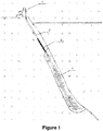
- Figure-1 represents a general view of the system (A) that can be used in the production of all kinds of hydrocarbons from gas hydrate formations which are exist under frozen layers of earth (permafrost) in the cold regions or sea floor or slopes.
- the main components of the system (A) are as follows: a drilling machine lowering and controlling equipment (1), a production tubing (2), a drilling machine (3), and a stripped production tubing (4) which is used preferably only along the gas hydrate formation.
- Said production tubing (2) is the same as the production tubing used in the prior art.
- Figure-2 represents a view of the stripped production tubing (4) which is drilled in the form of strips beforehand and filled with a pressure resistant material which can be easily drilled by means of a drilling bit (33) of the drilling machine (3).
- plug (41) filled areas on said stripped production tubing (4) are referred to as plug (41) within the description.
- Said plug (41) has a different color from the stripped production tubing (4) color so that plug (41) is detected by means of the sensor (37).
- the drilling bit (33) of the drilling machine (3) needs to reach the formation easily from the inside of the stripped production tubing(4) with plugs (41) to formation. So, stripped production tubing (4) is drilled in the form of strips along the body beforehand. And in order to have only targeted level effected from depressurization, the holes (5) at the upper levels need to remain covered and sealed. For that reason, said strips are filled with a pressure resistant material and sealed and that can be drilled and ripped easily by means of the drilling bit (33), thereby becoming a plug (41).
- the material of said plug (41) can be a micaceous organic or composite material that is pressure resistant and sealed and that can be drilled and ripped easily. Preferably, a wooden material can be used which is pressure resistant and sealed and can be drilled and ripped easily.
- the well profiles may be sloped depending on the shape of the gas hydrate formation. Accordingly, the stripped production tubing (4) may need to be bent depending on the well profile; that is to say, the plug (41) needs to change shape together with the stripped production tubing (4).
- the plug (41) may be exposed to different pressures depending on different well depths and well shapes may be different and thus the material of the plug (41) may vary. Wooden or micaceous organic or composite materials can be used as the material of the plug (41) based on the well shape and pressure. For instance, using wooden material can be an adequate and economical solution for the plugs (41) in less sloped wells.
- plug (41) material is also expected to be easily drilled and ripped by drilling bit (33)
- a plug removal tool (38) is attached on the drilling machine (3) for removal of the plug (41) so that cheeper plug (41) material is prefered and plug (41) is removed by plug removal tool (38) rather than drilling bit (33).
- Drilled strips along the body of the stripped production tubing (4) are equally spaced circumferentially.
- the width of the each strip is wide enough for drilling bit (33) passing through.
- the width of the strip is wider than the drilling bit width by taking into consideration the oscillation of the drilling bit (33).
- the diameters of the stripped production tubing (4) may vary. Therefore, the number of strips drilled all around may vary depending on the diameter of the stripped production tubing (4).
- the drilled strips have a length such that bended drilling bit (33) enters into the formation after passing (drilling) through the plug (41) without contacting with the stripped production tubing (4).
- the strips may be drilled in a staggered way or in parallel to each other along the stripped production tubing (4).
- Corners of the drilled strips are rounded so that the drilling bit (33) is prevented from contacting sharp corners and getting damaged.
- the rounded corners also help the plug (41) is better fastened into the drilled strip and sealed.
- Figure-3 represents a view of the drilling machine lowering and controlling equipment (1).
- the drilling machine lowering and controlling equipment (1) provides power and control required for lowering the drilling machine (3) into the well, drilling the plugs (41) and holes (5) into formation, allowing the drilling machine (3) to keep drilling the plugs (41) during gas production and pulling the drilling machine (3) out of the well.
- First element of the drilling machine lowering and controlling equipment (1) is pressure container (11).
- the drums, on which the cables are stored, are located inside pressure container (11).
- the pressure container (11) is pressure bearing to internal pressure which is higher than wellhead pressure.
- produced gas fills in the pressure container (11).
- pressure container (11) is filled with non-hazardous gases such as nitrogen or with water and pressurized up to the wellhead pressure.
- the second element of the drilling machine lowering and controlling equipment (1) is drilling machine loading pipe (12).
- the drilling machine (3) is located inside the drilling machine loading pipe (12) before being lowered into the well. Length of the drilling machine loading pipe (12) is more than total length of the drilling machine (3); therefore, the drilling machine (3) can be isolated inside the drilling machine loading pipe (12). Even when the well is under pressure, the drilling machine loading pipe (12) enables lowering the drilling machine (3) into the well or to pulling the same out of the well.
- the drilling machine loading pipe (12) is pressure bearing to internal pressure which is higher than wellhead pressure. During gas production, produced gas fills in the drilling machine loading pipe (12).
- the third element of the drilling machine lowering and controlling equipment (1) is cable roller (14). All cables and hoses such as power cable, control cable, display cable, water hose, chemical injection hose and drilling machine carrying cable pass through the cable roller (14).
- the cable roller (14) transfers the cables and hoses from the drilling machine loading pipe (12) to the cable carrying pipe (15).
- the cable roller (14) is pressure bearing to internal pressure which is higher than wellhead pressure. During gas production, produced gas fills in the cable roller (14).
- Cable carrying pipe (15) is the fourth element of the drilling machine lowering and controlling equipment (1).
- Said cable carrying pipe (15) is the one between the pressure container (11) and the cable roller (14).
- the cable carrying pipe (15) is pressure bearing to internal pressure which is higher than wellhead pressure. During gas production, produced gas fills in the cable carrying pipe (15).
- the fifth element of the drilling machine lowering and controlling equipment (1) is cable cutter (16). If an emergency arises and it is required to shut down the wellhead valves and isolate the well immediately, even without waiting for drilling machine (3) is pulled back into drilling machine loading pipe (12) from well, cable cutter (16) cuts cables and hoses allowing these cables and hoses to fall into the well and enables wellhead valves isolating the well.
- the cable cutter (16) is located between the drilling machine loading pipe (12) and the wellhead.
- the cable cutter (16) is pressure bearing to internal pressure which is higher than wellhead pressure. During gas production, produced gas fills in the cable cutter (16).
- the sixth element of said drilling machine lowering and controlling equipment (1) is power and control equipment (17). It provides required power and control for drilling machine (3) including surveillance, display and location determination required for operation of the drilling machine (3) and pressure control of the system (A).
- Figure-4 represents a view of the sealing element (13) which is seventh element of the drilling machine lowering and controlling equipment (1).
- the sealing element (13) prevents the produced gas entering into the pressure container (11) during the gas production if it is preferred to isolate pressure container (11) from produced gas.
- the sealing element (13) consists of pressure chambers (131) arranged in stages. Each pressure chamber (131) is filled with a non-hazardous gas such as nitrogen or the like or with water and pressurized up to the wellhead pressure.
- a non-hazardous gas such as nitrogen or the like or with water and pressurized up to the wellhead pressure.
- each pressure chamber (131) is individually measured by means of pressure sensor (132). Pressure difference is distributed equally among the pressure chambers (131) and pressure inside the each pressure chamber (131) is individually adjusted by injecting or draining non-hazardous gas or water into the pressure chamber (131).
- each sealing gasket (133) functions under comparatively smaller pressure differences in comparison with overall pressure difference. Said sealing gasket (133) is elastic.
- This carrying cable (134) which is strong enough to carry the total weight of the the cables and hoses and the drilling machine (3) itself. This carrying cable (134) passes through said sealing element (13).
- the carrying cable (134) is the part which carries the all weight. In this manner, it is possible to simplify the sealing element (13) and cable drum arrangements.
- Figure-5 represents a view of the drilling machine (3).
- Main components of the drilling machine (3) are drilling bit (33), drilling bit casing (331), stabilizer legs (31), fixing legs (32) and drilling machine body (34).
- a sensor (37) is also provided.
- the colored plug (41) is detected by means of the sensor (37) and the drilling bit (33) is positioned.
- Drilling machine (3) secures itself inside the stripped production tubing (4) and drills the plugs (41) and holes (5) into the formation.
- the drilling machine (3) occupies partially the interior of the stripped production tubing (4) so that continuous gas and water pass are possible there between. Upward and downward movement of the drilling machine (3) inside the well is provided by self weight of the drilling machine (3) and the carrying cable (134).
- the drilling bit (33) is the component which drills the plugs (41) and drills holes (5) into the formation.
- the diameters and characteristics of the drilling bit (33) can vary.
- water jet is used for drilling.
- tip of the drilling bit has jet nozzles and drilling bit is hollow.
- the drilling bit (33) is located inside the drilling bit casing (331). Water of water jet is heated and pressurized in the drilling bit casing (331), if water jet drilling is used. While drilling bit (33) is driven into formation, a pressure sensor measures water pressure of water jet inside the drilling bit casing (331) and forwarding speed of the drilling bit (33) is adjusted accordingly to minimize tear and wear of the drilling bit (33).
- the plug removal tool (38) is attached to drilling machine (3).
- Plug removal tool (38) is a circular saw which is driven into the plug (41) for removal of the plug (41).
- Figure-6 represents a view of the stabilizer legs (31) that allow for drilling bit casing (331) to remain stable during drilling.
- the stabilizer leg springs (312) connect the stabilizer leg shoe (311) to the body of the stabilizer leg (31).
- Figure-7 represents a view of the fixing legs (32) that allow for securing the drilling machine (3).
- the drilling machine (3) is secured inside the stripped production tubing (4) by means of the fixing legs (32).
- the contact surface of the fixing legs (32) has electromagnetic leg shoes (321).
- the electromagnetic leg shoes (321) stick to the inner surface of the stripped production tubing (4) and secure the drilling machine (3).
- Figure-8 represents a detailed view of the electromagnetic leg shoes (321).
- Fixing leg springs (322) are provided under the electromagnetic leg shoes (321). Said fixing leg springs (322) allows electromagnetic leg shoes (321) are pushed into the fixing legs (32) which allow the drilling machine (3) to move inside the stripped production tubing (4) without being obstructed.
- Figure-10 represents a cross section view of the drilling machine body (34).
- the drilling machine body (34) leaves enough space inside the stripped production tubing (4) for the gas and water to pass through.
- Motors are provided in the drilling machine body (34).
- Drill chuck rotating shaft (361) is driven by one of the motors.
- the drill chuck (36) is a component which holds the drilling bit (33) tightly or releases the same and preferably operates magnetically.
- the drilling bit (33) passes through the drill chuck (36).
- the magnetic drill chuck (36) is furnished with the drill chuck bearings (362) in order to provide rotational motion.
- the drill chuck (36) is driven by the drill chuck rotating shaft (361).
- the slide forwarding shaft (351) is driven by another motor.
- the slide forwarding shaft (351) is the shaft which moves the drilling bit (33) forward or backward by moving the slide (35) forward and backward.
- a slide (35) is provided between the front and rear sides of the drilling machine body (34).
- the slide (35) moves among the drill chuck rotating shaft (361), slide forwarding shaft (351) and slide shaft (56).
- Figure-9 represents a view of the slide (35).
- Figure-11 represents a view of the drilling bit (33) inside the drilling machine body (34). As seen in the figure, guiding rollers (332) are provided. The drilling bit (33) is guided into the formation by means of the guiding rollers (332).
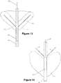
- Figure-12 represents an upper plan view of drilled holes (5) into formation at targeted level and dissociated void spaces around holes (5).
- the stripped production tubing (4) is depressurized causing a region of low pressure spread through the holes (5) drilled into formation. Low pressure causes the formation to dissociate and release gas and water. As produced gas reaches the wellhead and free water flushes into the well, holes (5) expand and void spaces are created around the holes (5) initiating a cavern (6).
- Figure-13 represents a view of holes (5) drilled into formation at targeted level and a cavern (6) formed at targeted level.
- low pressure at the targeted level is maintained.
- Low pressure causes the formation to further dissociate and to further release gas and water.
- void spaces which were already created around holes (5), expand and form a cavern (6) in the formation at targeted level.
- Figure-14 represents a view of holes (5) drilled into formation level at upper level and cavern (6) is expanded upwards.
- the method developed to obtain gas from gas hydrate formation comprises basically the process steps according to claim 1.
- a well is drilled with conventional methods into the gas hydrate formations under the frozen layers of earth (permafrost) in the cold regions or sea floor/slopes.
- the well profile may be vertical or sloped depending on the shape of the gas hydrate formation. Or bent from vertical position to horizontal position with a certain radius.
- Depressurization of stripped production tubing (4) is provided by removing water from the well at the beginning. But later dissociated water from drilled holes (5) flushes into well. If not removed, pressure increases at the targeted level. Pressure at targeted level becomes sum of height of the water column in stripped production tubing (4) above targeted level and gas pressure. So water removal is required during gas production for depressurization of targeted level. For elimination of the water removal from stripped production tubing (4) during gas production, alternatively well is drilled deep enough to store the dissociated water coming from first level and if used water volume of water jet.
- the stripped production tubing (4) is lowered into the well.
- Said stripped production tubing (4) is used preferably only along the gas hydrate formation.
- conventional production tubing (2) is used from the top level of the gas hydrate formation reaching the wellhead.
- the drilling machine lowering and controlling equipment (1) is mounted to the wellhead valves.
- the drilling machine (3) is located inside the drilling machine loading pipe (12) and all cables and hoses are connected to the drilling machine (3) and all are wound to the drum of drilling machine lowering and controlling equipment (1).
- the drilling machine (3) is lowered to targeted level through the production tubing (2) and then the stripped production tubing (4) by drilling machine lowering and controlling equipment (1).
- the stabilizer legs (31) allow the drilling machine (3) to move inside the production tubing (2) and the stripped production tubing (4) without getting caught.
- the sensor (37) on the drilling machine (3) which is now at the targeted level, detects the colored plugs (41) on the stripped production tubing (4) and the drill bit (3) is positioned.
- the drilling bit (33) drills the plug (41) and reaches the formation.
- the drilling bit (33) reaching the formation forms a hole (5) in the formation.
- hole (5) drilled with a slope for better draining of dissociated water from formation.
- the drilling bit (33) is pulled back into the drilling bit casing (331) thus diffusing low pressure into the formation through drilled holes (5).
- Drilling the plugs (41) and drilling holes (5) into formation continue during dissociation of the targeted level. More than one hole (5) may be drilled using same strip on the stripped production tubing (4) where drill bit (33) is guided to different directions by means of the guiding rollers (332).
- Pressure at targeted level is sum of gas pressure and water pressure where water pressure is a function of height of the water column above targeted level.
- Pressure at targeted level is measured by means of pressure sensor and water level is measured by means of level sensor on the drilling machine (3) and gas pressure is measured at wellhead. Comparison of gas and water pressure and water level enables to understand conditions at targeted level. For example; If pressure at targeted level measured high, it means either water pressure or gas pressure is high. Then it is necessary to look at water level. If water level is low it means that gas pressure at targeted level is high. So produced gas volume at wellhead is adjusted to respond high gas pressure case. Pressure control and subsequent controlled removal of produced gas from wellhead enables low pressure is maintained at targeted level and sudden decrease or increase in the gas pressure is avoided as explained above. In extreme cases, if required, water inside the stripped production tubing (4) is discharged by means of pump or water let into the well.
- cavern (6) Once a cavern (6) is formed next step is expanding the cavern(6) upwards. Distance between two levels is so selected that upper level is connected to cavern (6) after a while during dissociation. This provides water dissociated at upper level is filled into cavern (6) forming a dissociated water pool in the cavern (6).
- Amount of produced gas provides an opinion about the size of the cavern (6) and depth of the drilled holes (5) helps to estimate height of the cavern (6). While selecting the distance between two levels, it is aimed to connect void spaces created around holes (5) to cavern (6) during dissociation of the upper level so that the distance is selected according to the height of the cavern (6).
- the observed density of gas hydrate is around 0.9 g/cm 3 , which means that gas hydrate floats to the surface of water and gas continue to dissolve from partially dissociated formation.
- Dissociated water pool having much more surface area when compared with inside diameter of stripped production tubing (4), provides more opportunity for partially dissociated gas hydrate dissolving more gas.
- Chemicals used for inhibition of re-freezing of the dissociated void spaces around holes (5) at upper levels also drain into the dissociated water pool in the cavern and inhibition continues in the water pool.
- Dissociated water pool also eliminates pumping need for dissociated water and partially dissociated gas hydrate to ground level and dissolving gas from dissociated water at ground level.
- drilling machine (3) When drilling machine (3) is moved to a new level for removing the plugs (41) and drilling holes (5) into formation, the new level exposes to low pressure and starts dissociate.
- All of the plugs (41) and holes (5) are drilled in level by level throughout the stripped production tubing (4). Gas is produced from the formation reaches the surface through the production tubings (2,4) and water remains inside the formation.
Landscapes
- Geology (AREA)
- Life Sciences & Earth Sciences (AREA)
- Engineering & Computer Science (AREA)
- Mining & Mineral Resources (AREA)
- Environmental & Geological Engineering (AREA)
- Fluid Mechanics (AREA)
- Physics & Mathematics (AREA)
- General Life Sciences & Earth Sciences (AREA)
- Geochemistry & Mineralogy (AREA)
- Chemical & Material Sciences (AREA)
- Dispersion Chemistry (AREA)
- Earth Drilling (AREA)
- Drilling And Exploitation, And Mining Machines And Methods (AREA)
Claims (7)
- Procédé pour obtention de gaz à partir de formations d'hydrates de gaz sous des couches de terre gelées dans des régions froides ou sur le fond marin, comprenant les étapes de procédé suivantes de;a. forer un puits coupant une formation d'hydrates de gaz,b. placer un tube de production dénudé (4) à travers la formation d'hydrates de gaz dans le puits foré, ledit tube dénudé comprenant une paroi et des ouvertures pré-forées à travers la paroi, lesdites ouvertures se présentant sous la forme de bandes et étant remplies d'un matériau résistant à la pression, les ouvertures remplies définissant des bouchons (41),b'. l'installation d'une tête de puits,c. sélectionner une élévation inférieure dans la formation d'hydrates de gaz comme premier niveau ciblé,d. éliminer l'eau du puits fournissant ainsi la dépressurisation du tube de production dénudé (4) à une basse pression,e. amener une foreuse (3) au niveau ciblé de la formation d'hydrates de gaz à travers le tube de production dénudé (4) au moyen d'un équipement (1) d'abaissement et de commande d'une foreuse,f. forer les bouchons (41) dans les ouvertures du tube de production dénudé (4) au niveau ciblé de la formation d'hydrates de gaz au moyen d'un trépan (33) de ladite foreuse (3), la largeur de chaque ouverture est suffisamment large pour permettre le passage de la mèche de forage,g. forer des trous (5) dans la formation d'hydrates de gaz au moyen du trépan (33), tirer ledit trépan (33) dans le tube de production dénudé (4), et permettre la dissociation de la formation en gaz et en eau grâce à la diffusion de la basse pression à l'intérieur du tube dénudé dans la formation par les trous forés (5),h. contrôler le niveau d'eau et de la pression de l'eau à l'intérieur du tube de production dénudé (4) et de la quantité de gaz produit par la tête de puits pour maintenir une basse pression au niveau visé pendant que le gaz et l'eau dissociés sont remplacés par une cavité (6),i. répéter les étapes e, f, g, h, autant de fois qu'il y a de niveaux cibles identifiés dans la formation d'hydrate de gaz, commencer par l'élévation inférieure jusqu'à une élévation supérieure associée à un niveau ciblé,j. obtenir le gaz séparé de la tête de puits.
- Procédé selon la revendication 1, caractérisé en ce que après l'étape de procédé (e). le trépan (33) sur la foreuse (3) est positionné en détectant les bouchons (41) sur le tube de production dénudé (4) à l'aide d'un capteur (37).
- Procédé selon la revendication 1, caractérisé en ce que forer des trous (5) dans la formation à l'étape (g) est réalisé au moyen d'un jet d'eau à l'aide d'un trépan (33).
- Procédé selon la revendication 3, caractérisé en ce que ladite eau du jet d'eau est chauffée dans un boîtier de trépan (331) dans le puits.
- Procédé selon la revendication 1, caractérisé en ce que le puits mentionné à l'étape de procédé (a) foré dans la formation d'hydrate de gaz est suffisamment profond pour stocker l'eau dissociée provenant d'au moins le premier niveau dissocié.
- Procédé selon la revendication 3, caractérisé en ce que injecter les produits chimiques dans le jet d'eau et les pulvériser sur les parties adjacentes de la formation pour empêcher la recongélation.
- Procédé selon la revendication 1, caractérisé en ce que le premier niveau ciblé est l'élévation la plus basse de la formation d'hydrates de gaz.
Applications Claiming Priority (2)
| Application Number | Priority Date | Filing Date | Title |
|---|---|---|---|
| PCT/TR2015/000051 WO2016133470A1 (fr) | 2015-02-16 | 2015-02-16 | Système et procédé d'exploitation de gaz issu de formations d'hydrate de gaz |
| PCT/TR2016/050037 WO2016133480A1 (fr) | 2015-02-16 | 2016-02-12 | Système et procédé d'exploitation de gaz produit dans des formations d'hydrate de gaz |
Publications (2)
| Publication Number | Publication Date |
|---|---|
| EP3122990A1 EP3122990A1 (fr) | 2017-02-01 |
| EP3122990B1 true EP3122990B1 (fr) | 2019-07-03 |
Family
ID=52815249
Family Applications (2)
| Application Number | Title | Priority Date | Filing Date |
|---|---|---|---|
| EP15714976.6A Withdrawn EP3071785A1 (fr) | 2015-02-16 | 2015-02-16 | Système et procédé d'exploitation de gaz issu de formations d'hydrate de gaz |
| EP16710031.2A Active EP3122990B1 (fr) | 2015-02-16 | 2016-02-12 | Système et procédé d'exploitation de gaz produit dans des formations d'hydrate de gaz |
Family Applications Before (1)
| Application Number | Title | Priority Date | Filing Date |
|---|---|---|---|
| EP15714976.6A Withdrawn EP3071785A1 (fr) | 2015-02-16 | 2015-02-16 | Système et procédé d'exploitation de gaz issu de formations d'hydrate de gaz |
Country Status (5)
| Country | Link |
|---|---|
| US (1) | US10927656B2 (fr) |
| EP (2) | EP3071785A1 (fr) |
| CA (1) | CA2976894C (fr) |
| RU (1) | RU2665930C1 (fr) |
| WO (2) | WO2016133470A1 (fr) |
Families Citing this family (10)
| Publication number | Priority date | Publication date | Assignee | Title |
|---|---|---|---|---|
| CN106761587B (zh) * | 2016-11-18 | 2018-04-20 | 青岛海洋地质研究所 | 海洋粉砂质储层天然气水合物多分支孔有限防砂开采方法 |
| CN109653713A (zh) * | 2018-12-20 | 2019-04-19 | 成都理工大学 | 一种天然气水合物曲井钻采装置 |
| CN109538170A (zh) | 2019-01-21 | 2019-03-29 | 吉林大学 | 射流法原位开采天然气水合物的加压试验装置与方法 |
| CN110029968B (zh) * | 2019-04-08 | 2020-02-14 | 中国石油大学(华东) | 用于钻取水合物微小井眼并快速完井的装置及工作方法 |
| CN110821448B (zh) * | 2019-11-14 | 2022-02-18 | 中国科学院广州能源研究所 | 一种海相天然气水合物的开采方法及开采装置 |
| CN111622717A (zh) * | 2020-06-29 | 2020-09-04 | 青岛新胜石油机械有限公司 | 全智能紧凑封闭型超长冲程抽油机构 |
| CN113252507B (zh) * | 2021-04-27 | 2022-03-22 | 青岛海洋地质研究所 | 不同埋深水合物藏的扰动与稳定性分析方法 |
| CN113899856B (zh) * | 2021-08-27 | 2023-08-08 | 西南石油大学 | 一种隧道有害气体超前钻孔随钻实时检测设备 |
| CN117248902B (zh) * | 2023-11-17 | 2024-02-06 | 乐山市通达交通勘察设计有限责任公司 | 隧道有害气体随钻检测超前探测装置 |
| CN119021583B (zh) * | 2024-08-15 | 2025-11-07 | 中煤科工集团重庆研究院有限公司 | 煤层瓦斯抽采径向多分支孔水力喷射快速成孔装置 |
Citations (1)
| Publication number | Priority date | Publication date | Assignee | Title |
|---|---|---|---|---|
| US20090014174A1 (en) * | 2006-12-29 | 2009-01-15 | Encana Corporation | Use of coated slots for control of sand or other solids in wells completed for production of fluids |
Family Cites Families (24)
| Publication number | Priority date | Publication date | Assignee | Title |
|---|---|---|---|---|
| US2401035A (en) * | 1944-01-26 | 1946-05-28 | Nobs Chemical Company | Well screen |
| GB9003617D0 (en) | 1990-02-16 | 1990-04-11 | Shell Int Research | A method for preventing hydrates |
| RU2026999C1 (ru) * | 1991-03-05 | 1995-01-20 | Черней Эдуард Иванович | Газогидратный комплекс |
| RU2175058C2 (ru) * | 1999-03-22 | 2001-10-20 | Шарифуллин Ришад Яхиевич | Способ воздействия на призабойную зону пласта и устройство для его осуществления |
| DE19940327C1 (de) * | 1999-08-25 | 2001-05-03 | Meyer Rohr & Schacht Gmbh | Vortriebsrohr für die Herstellung einer im wesentlichen horizontal verlaufenden Rohrleitung sowie Rohrleitung |
| JP2003193788A (ja) * | 2001-12-27 | 2003-07-09 | Mitsubishi Heavy Ind Ltd | ガスハイドレート掘削回収方法及び掘削回収システム |
| JP3506696B1 (ja) * | 2002-07-22 | 2004-03-15 | 財団法人応用光学研究所 | 地下賦存炭化水素ガス資源収集装置および収集方法 |
| JP2005029984A (ja) | 2003-07-08 | 2005-02-03 | Hitachi Constr Mach Co Ltd | 建設機械用作業腕及びその製造方法 |
| US7784545B2 (en) * | 2004-05-14 | 2010-08-31 | Maguire James Q | In-situ method of fracturing gas shale and geothermal areas |
| US9080406B2 (en) * | 2004-09-21 | 2015-07-14 | Benthic Geotech Pty Ltd | Remote gas monitoring apparatus for seabed drilling |
| CN1587642A (zh) * | 2004-09-21 | 2005-03-02 | 中国科学院广州能源研究所 | 一种海洋天然气水合物开采的方法及装置 |
| WO2007072172A1 (fr) * | 2005-12-20 | 2007-06-28 | Schlumberger Technology B.V. | Procede et systeme de developpement de formations porteuses d'hydrocarbures et comprenant la depressurisation des hydrates de gaz |
| GB2449010B (en) * | 2006-02-09 | 2011-04-20 | Weatherford Lamb | Managed temperature drilling system and method |
| CN1944950A (zh) * | 2006-08-09 | 2007-04-11 | 中国石油大学(华东) | 井下气水分离水回注开采海底水合物的方法 |
| CN100587227C (zh) * | 2007-02-13 | 2010-02-03 | 中国科学院广州能源研究所 | 一种开采天然气水合物的方法及装置 |
| US8505621B2 (en) * | 2010-03-30 | 2013-08-13 | Halliburton Energy Services, Inc. | Well assembly with recesses facilitating branch wellbore creation |
| RU2438009C1 (ru) * | 2010-05-04 | 2011-12-27 | Государственное образовательное учреждение высшего профессионального образования Российский государственный университет нефти и газа имени И.М. Губкина | Способ разработки газогидратных месторождений |
| US9187977B2 (en) * | 2010-07-22 | 2015-11-17 | Exxonmobil Upstream Research Company | System and method for stimulating a multi-zone well |
| WO2012061027A1 (fr) * | 2010-10-25 | 2012-05-10 | Conocophillips Company | Production sélective d'hydrates avec co2 et décompression maîtrisée |
| CN102322245B (zh) * | 2011-05-26 | 2013-11-06 | 上海交通大学 | 天然气水合物开采装置 |
| WO2012178020A1 (fr) | 2011-06-22 | 2012-12-27 | Bruce Donald Jette | Système de forage en tunnel robotique |
| RU2489568C1 (ru) * | 2012-03-05 | 2013-08-10 | Александр Валентинович Воробьев | Способ добычи подводных залежей газовых гидратов и подводный добычный комплекс газовых гидратов |
| GB2503672A (en) * | 2012-07-03 | 2014-01-08 | Caltec Ltd | Apparatus for minimising the effect of joule-thomson cooling |
| US9611695B2 (en) * | 2013-04-12 | 2017-04-04 | The Charles Machine Works, Inc. | Dual pipe drilling head with improved bearing retention structure |
-
2015
- 2015-02-16 WO PCT/TR2015/000051 patent/WO2016133470A1/fr not_active Ceased
- 2015-02-16 EP EP15714976.6A patent/EP3071785A1/fr not_active Withdrawn
-
2016
- 2016-02-12 WO PCT/TR2016/050037 patent/WO2016133480A1/fr not_active Ceased
- 2016-02-12 RU RU2017131525A patent/RU2665930C1/ru active
- 2016-02-12 CA CA2976894A patent/CA2976894C/fr active Active
- 2016-02-12 EP EP16710031.2A patent/EP3122990B1/fr active Active
- 2016-02-12 US US15/551,350 patent/US10927656B2/en active Active
Patent Citations (1)
| Publication number | Priority date | Publication date | Assignee | Title |
|---|---|---|---|---|
| US20090014174A1 (en) * | 2006-12-29 | 2009-01-15 | Encana Corporation | Use of coated slots for control of sand or other solids in wells completed for production of fluids |
Also Published As
| Publication number | Publication date |
|---|---|
| WO2016133480A1 (fr) | 2016-08-25 |
| EP3071785A1 (fr) | 2016-09-28 |
| RU2665930C1 (ru) | 2018-09-05 |
| US10927656B2 (en) | 2021-02-23 |
| US20180045029A1 (en) | 2018-02-15 |
| CA2976894C (fr) | 2019-12-03 |
| WO2016133470A1 (fr) | 2016-08-25 |
| EP3122990A1 (fr) | 2017-02-01 |
| CA2976894A1 (fr) | 2016-08-25 |
Similar Documents
| Publication | Publication Date | Title |
|---|---|---|
| EP3122990B1 (fr) | Système et procédé d'exploitation de gaz produit dans des formations d'hydrate de gaz | |
| US9732561B2 (en) | Method and apparatus for increasing well productivity | |
| CN110067534B (zh) | 喷射软管承载系统 | |
| EP2458137B1 (fr) | Unité de fonds de puits sans fil | |
| EP1050661A2 (fr) | Améliorations concernant le forage sous-marin de puits | |
| US9567809B2 (en) | Apparatus and method for lateral well drilling | |
| JP5316878B2 (ja) | メタンハイドレートからのメタンガス生産装置及びこれを用いたメタンハイドレートからのメタンガス生産方法 | |
| US20070144738A1 (en) | Method and system for development of hydrocarbon bearing formations including depressurization of gas hydrates | |
| MXPA02007728A (es) | Metodo y aparato para la estimulacion de intervalos de formacion multiples. | |
| CA2714935A1 (fr) | Acces a un reservoir confine (tranchee) a face ouverte pour traitements de drainage par gravite | |
| NO325928B1 (no) | Anordning og fremgangsmate for rotering av en del av en borestreng | |
| US20120067646A1 (en) | Apparatus and Method for Lateral Well Drilling | |
| DK2550422T3 (en) | Pressurized well construction and operation systems and methods that can be used to kulbrinteoperationer, storage and resolution | |
| CN107461186B (zh) | 分支井储层改造装置及改造方法 | |
| CN109057757A (zh) | 一种天然气水合物开采方法及装置 | |
| CA2794346A1 (fr) | Construction de puits a pression regulee et systemes et procedes de fonctionnement utilisables pour des operations, le stockage et l'extraction par dissolution d'hydrocarbures | |
| WO2011119197A1 (fr) | Construction de puits à pression régulée et systèmes et procédés de fonctionnement utilisables pour des opérations, le stockage et l'extraction par dissolution d'hydrocarbures | |
| US20140008129A1 (en) | Multidirectional wellbore penetration system and methods of use | |
| EP3207212B1 (fr) | Système d'isolation de puits de forage et procédé associé | |
| US20180010425A1 (en) | Wellbore lining for natural gas hydrate | |
| US8863862B1 (en) | Lateral drilling tool and method from vertical bore hole | |
| US12480385B2 (en) | Method for downhole chemical storage for well mitigation and reservoir treatments | |
| US12163393B2 (en) | Multi-function mandrel system | |
| US11732182B1 (en) | Thermochemical soap stick for well lifting and deliquification | |
| RU2320843C1 (ru) | Способ строительства скважин с отдаленным забоем |
Legal Events
| Date | Code | Title | Description |
|---|---|---|---|
| STAA | Information on the status of an ep patent application or granted ep patent |
Free format text: STATUS: THE INTERNATIONAL PUBLICATION HAS BEEN MADE |
|
| PUAI | Public reference made under article 153(3) epc to a published international application that has entered the european phase |
Free format text: ORIGINAL CODE: 0009012 |
|
| STAA | Information on the status of an ep patent application or granted ep patent |
Free format text: STATUS: REQUEST FOR EXAMINATION WAS MADE |
|
| 17P | Request for examination filed |
Effective date: 20161025 |
|
| AK | Designated contracting states |
Kind code of ref document: A1 Designated state(s): AL AT BE BG CH CY CZ DE DK EE ES FI FR GB GR HR HU IE IS IT LI LT LU LV MC MK MT NL NO PL PT RO RS SE SI SK SM TR |
|
| AX | Request for extension of the european patent |
Extension state: BA ME |
|
| STAA | Information on the status of an ep patent application or granted ep patent |
Free format text: STATUS: EXAMINATION IS IN PROGRESS |
|
| 17Q | First examination report despatched |
Effective date: 20170209 |
|
| DAV | Request for validation of the european patent (deleted) | ||
| DAX | Request for extension of the european patent (deleted) | ||
| GRAP | Despatch of communication of intention to grant a patent |
Free format text: ORIGINAL CODE: EPIDOSNIGR1 |
|
| STAA | Information on the status of an ep patent application or granted ep patent |
Free format text: STATUS: GRANT OF PATENT IS INTENDED |
|
| INTG | Intention to grant announced |
Effective date: 20190311 |
|
| GRAS | Grant fee paid |
Free format text: ORIGINAL CODE: EPIDOSNIGR3 |
|
| GRAA | (expected) grant |
Free format text: ORIGINAL CODE: 0009210 |
|
| STAA | Information on the status of an ep patent application or granted ep patent |
Free format text: STATUS: THE PATENT HAS BEEN GRANTED |
|
| AK | Designated contracting states |
Kind code of ref document: B1 Designated state(s): AL AT BE BG CH CY CZ DE DK EE ES FI FR GB GR HR HU IE IS IT LI LT LU LV MC MK MT NL NO PL PT RO RS SE SI SK SM TR |
|
| REG | Reference to a national code |
Ref country code: GB Ref legal event code: FG4D |
|
| REG | Reference to a national code |
Ref country code: CH Ref legal event code: EP Ref country code: AT Ref legal event code: REF Ref document number: 1151213 Country of ref document: AT Kind code of ref document: T Effective date: 20190715 |
|
| REG | Reference to a national code |
Ref country code: IE Ref legal event code: FG4D |
|
| REG | Reference to a national code |
Ref country code: DE Ref legal event code: R096 Ref document number: 602016016276 Country of ref document: DE |
|
| REG | Reference to a national code |
Ref country code: NL Ref legal event code: FP |
|
| REG | Reference to a national code |
Ref country code: NO Ref legal event code: T2 Effective date: 20190703 |
|
| REG | Reference to a national code |
Ref country code: LT Ref legal event code: MG4D |
|
| REG | Reference to a national code |
Ref country code: AT Ref legal event code: MK05 Ref document number: 1151213 Country of ref document: AT Kind code of ref document: T Effective date: 20190703 |
|
| PG25 | Lapsed in a contracting state [announced via postgrant information from national office to epo] |
Ref country code: FI Free format text: LAPSE BECAUSE OF FAILURE TO SUBMIT A TRANSLATION OF THE DESCRIPTION OR TO PAY THE FEE WITHIN THE PRESCRIBED TIME-LIMIT Effective date: 20190703 Ref country code: CZ Free format text: LAPSE BECAUSE OF FAILURE TO SUBMIT A TRANSLATION OF THE DESCRIPTION OR TO PAY THE FEE WITHIN THE PRESCRIBED TIME-LIMIT Effective date: 20190703 Ref country code: AT Free format text: LAPSE BECAUSE OF FAILURE TO SUBMIT A TRANSLATION OF THE DESCRIPTION OR TO PAY THE FEE WITHIN THE PRESCRIBED TIME-LIMIT Effective date: 20190703 Ref country code: SE Free format text: LAPSE BECAUSE OF FAILURE TO SUBMIT A TRANSLATION OF THE DESCRIPTION OR TO PAY THE FEE WITHIN THE PRESCRIBED TIME-LIMIT Effective date: 20190703 Ref country code: BG Free format text: LAPSE BECAUSE OF FAILURE TO SUBMIT A TRANSLATION OF THE DESCRIPTION OR TO PAY THE FEE WITHIN THE PRESCRIBED TIME-LIMIT Effective date: 20191003 Ref country code: PT Free format text: LAPSE BECAUSE OF FAILURE TO SUBMIT A TRANSLATION OF THE DESCRIPTION OR TO PAY THE FEE WITHIN THE PRESCRIBED TIME-LIMIT Effective date: 20191104 Ref country code: LT Free format text: LAPSE BECAUSE OF FAILURE TO SUBMIT A TRANSLATION OF THE DESCRIPTION OR TO PAY THE FEE WITHIN THE PRESCRIBED TIME-LIMIT Effective date: 20190703 Ref country code: HR Free format text: LAPSE BECAUSE OF FAILURE TO SUBMIT A TRANSLATION OF THE DESCRIPTION OR TO PAY THE FEE WITHIN THE PRESCRIBED TIME-LIMIT Effective date: 20190703 |
|
| PG25 | Lapsed in a contracting state [announced via postgrant information from national office to epo] |
Ref country code: RS Free format text: LAPSE BECAUSE OF FAILURE TO SUBMIT A TRANSLATION OF THE DESCRIPTION OR TO PAY THE FEE WITHIN THE PRESCRIBED TIME-LIMIT Effective date: 20190703 Ref country code: IS Free format text: LAPSE BECAUSE OF FAILURE TO SUBMIT A TRANSLATION OF THE DESCRIPTION OR TO PAY THE FEE WITHIN THE PRESCRIBED TIME-LIMIT Effective date: 20191103 Ref country code: ES Free format text: LAPSE BECAUSE OF FAILURE TO SUBMIT A TRANSLATION OF THE DESCRIPTION OR TO PAY THE FEE WITHIN THE PRESCRIBED TIME-LIMIT Effective date: 20190703 Ref country code: GR Free format text: LAPSE BECAUSE OF FAILURE TO SUBMIT A TRANSLATION OF THE DESCRIPTION OR TO PAY THE FEE WITHIN THE PRESCRIBED TIME-LIMIT Effective date: 20191004 Ref country code: AL Free format text: LAPSE BECAUSE OF FAILURE TO SUBMIT A TRANSLATION OF THE DESCRIPTION OR TO PAY THE FEE WITHIN THE PRESCRIBED TIME-LIMIT Effective date: 20190703 Ref country code: LV Free format text: LAPSE BECAUSE OF FAILURE TO SUBMIT A TRANSLATION OF THE DESCRIPTION OR TO PAY THE FEE WITHIN THE PRESCRIBED TIME-LIMIT Effective date: 20190703 |
|
| PG25 | Lapsed in a contracting state [announced via postgrant information from national office to epo] |
Ref country code: EE Free format text: LAPSE BECAUSE OF FAILURE TO SUBMIT A TRANSLATION OF THE DESCRIPTION OR TO PAY THE FEE WITHIN THE PRESCRIBED TIME-LIMIT Effective date: 20190703 Ref country code: PL Free format text: LAPSE BECAUSE OF FAILURE TO SUBMIT A TRANSLATION OF THE DESCRIPTION OR TO PAY THE FEE WITHIN THE PRESCRIBED TIME-LIMIT Effective date: 20190703 Ref country code: DK Free format text: LAPSE BECAUSE OF FAILURE TO SUBMIT A TRANSLATION OF THE DESCRIPTION OR TO PAY THE FEE WITHIN THE PRESCRIBED TIME-LIMIT Effective date: 20190703 Ref country code: RO Free format text: LAPSE BECAUSE OF FAILURE TO SUBMIT A TRANSLATION OF THE DESCRIPTION OR TO PAY THE FEE WITHIN THE PRESCRIBED TIME-LIMIT Effective date: 20190703 Ref country code: IT Free format text: LAPSE BECAUSE OF FAILURE TO SUBMIT A TRANSLATION OF THE DESCRIPTION OR TO PAY THE FEE WITHIN THE PRESCRIBED TIME-LIMIT Effective date: 20190703 |
|
| PG25 | Lapsed in a contracting state [announced via postgrant information from national office to epo] |
Ref country code: SK Free format text: LAPSE BECAUSE OF FAILURE TO SUBMIT A TRANSLATION OF THE DESCRIPTION OR TO PAY THE FEE WITHIN THE PRESCRIBED TIME-LIMIT Effective date: 20190703 Ref country code: IS Free format text: LAPSE BECAUSE OF FAILURE TO SUBMIT A TRANSLATION OF THE DESCRIPTION OR TO PAY THE FEE WITHIN THE PRESCRIBED TIME-LIMIT Effective date: 20200224 Ref country code: SM Free format text: LAPSE BECAUSE OF FAILURE TO SUBMIT A TRANSLATION OF THE DESCRIPTION OR TO PAY THE FEE WITHIN THE PRESCRIBED TIME-LIMIT Effective date: 20190703 |
|
| REG | Reference to a national code |
Ref country code: DE Ref legal event code: R097 Ref document number: 602016016276 Country of ref document: DE |
|
| PLBE | No opposition filed within time limit |
Free format text: ORIGINAL CODE: 0009261 |
|
| STAA | Information on the status of an ep patent application or granted ep patent |
Free format text: STATUS: NO OPPOSITION FILED WITHIN TIME LIMIT |
|
| PG2D | Information on lapse in contracting state deleted |
Ref country code: IS |
|
| 26N | No opposition filed |
Effective date: 20200603 |
|
| PG25 | Lapsed in a contracting state [announced via postgrant information from national office to epo] |
Ref country code: SI Free format text: LAPSE BECAUSE OF FAILURE TO SUBMIT A TRANSLATION OF THE DESCRIPTION OR TO PAY THE FEE WITHIN THE PRESCRIBED TIME-LIMIT Effective date: 20190703 |
|
| REG | Reference to a national code |
Ref country code: CH Ref legal event code: PL |
|
| REG | Reference to a national code |
Ref country code: BE Ref legal event code: MM Effective date: 20200229 |
|
| PG25 | Lapsed in a contracting state [announced via postgrant information from national office to epo] |
Ref country code: LU Free format text: LAPSE BECAUSE OF NON-PAYMENT OF DUE FEES Effective date: 20200212 Ref country code: MC Free format text: LAPSE BECAUSE OF FAILURE TO SUBMIT A TRANSLATION OF THE DESCRIPTION OR TO PAY THE FEE WITHIN THE PRESCRIBED TIME-LIMIT Effective date: 20190703 |
|
| PG25 | Lapsed in a contracting state [announced via postgrant information from national office to epo] |
Ref country code: CH Free format text: LAPSE BECAUSE OF NON-PAYMENT OF DUE FEES Effective date: 20200229 Ref country code: LI Free format text: LAPSE BECAUSE OF NON-PAYMENT OF DUE FEES Effective date: 20200229 |
|
| PG25 | Lapsed in a contracting state [announced via postgrant information from national office to epo] |
Ref country code: IE Free format text: LAPSE BECAUSE OF NON-PAYMENT OF DUE FEES Effective date: 20200212 |
|
| PG25 | Lapsed in a contracting state [announced via postgrant information from national office to epo] |
Ref country code: BE Free format text: LAPSE BECAUSE OF NON-PAYMENT OF DUE FEES Effective date: 20200229 |
|
| PG25 | Lapsed in a contracting state [announced via postgrant information from national office to epo] |
Ref country code: MT Free format text: LAPSE BECAUSE OF FAILURE TO SUBMIT A TRANSLATION OF THE DESCRIPTION OR TO PAY THE FEE WITHIN THE PRESCRIBED TIME-LIMIT Effective date: 20190703 Ref country code: CY Free format text: LAPSE BECAUSE OF FAILURE TO SUBMIT A TRANSLATION OF THE DESCRIPTION OR TO PAY THE FEE WITHIN THE PRESCRIBED TIME-LIMIT Effective date: 20190703 |
|
| PG25 | Lapsed in a contracting state [announced via postgrant information from national office to epo] |
Ref country code: MK Free format text: LAPSE BECAUSE OF FAILURE TO SUBMIT A TRANSLATION OF THE DESCRIPTION OR TO PAY THE FEE WITHIN THE PRESCRIBED TIME-LIMIT Effective date: 20190703 |
|
| PGFP | Annual fee paid to national office [announced via postgrant information from national office to epo] |
Ref country code: NL Payment date: 20260214 Year of fee payment: 11 |
|
| PGFP | Annual fee paid to national office [announced via postgrant information from national office to epo] |
Ref country code: GB Payment date: 20260202 Year of fee payment: 11 |
|
| PGFP | Annual fee paid to national office [announced via postgrant information from national office to epo] |
Ref country code: DE Payment date: 20260218 Year of fee payment: 11 Ref country code: NO Payment date: 20260225 Year of fee payment: 11 |
|
| PGFP | Annual fee paid to national office [announced via postgrant information from national office to epo] |
Ref country code: FR Payment date: 20260224 Year of fee payment: 11 |
|
| PGFP | Annual fee paid to national office [announced via postgrant information from national office to epo] |
Ref country code: TR Payment date: 20260114 Year of fee payment: 11 |