EP3123018B1 - Générateur à turbine à gaz avec une turbine de puissance à pré-combustion - Google Patents
Générateur à turbine à gaz avec une turbine de puissance à pré-combustion Download PDFInfo
- Publication number
- EP3123018B1 EP3123018B1 EP15767948.1A EP15767948A EP3123018B1 EP 3123018 B1 EP3123018 B1 EP 3123018B1 EP 15767948 A EP15767948 A EP 15767948A EP 3123018 B1 EP3123018 B1 EP 3123018B1
- Authority
- EP
- European Patent Office
- Prior art keywords
- speed
- turbine
- generator
- combustion
- low
- Prior art date
- Legal status (The legal status is an assumption and is not a legal conclusion. Google has not performed a legal analysis and makes no representation as to the accuracy of the status listed.)
- Not-in-force
Links
Images


Classifications
-
- H—ELECTRICITY
- H02—GENERATION; CONVERSION OR DISTRIBUTION OF ELECTRIC POWER
- H02K—DYNAMO-ELECTRIC MACHINES
- H02K7/00—Arrangements for handling mechanical energy structurally associated with dynamo-electric machines, e.g. structural association with mechanical driving motors or auxiliary dynamo-electric machines
- H02K7/18—Structural association of electric generators with mechanical driving motors, e.g. with turbines
- H02K7/1807—Rotary generators
- H02K7/1823—Rotary generators structurally associated with turbines or similar engines
-
- F—MECHANICAL ENGINEERING; LIGHTING; HEATING; WEAPONS; BLASTING
- F01—MACHINES OR ENGINES IN GENERAL; ENGINE PLANTS IN GENERAL; STEAM ENGINES
- F01D—NON-POSITIVE DISPLACEMENT MACHINES OR ENGINES, e.g. STEAM TURBINES
- F01D15/00—Adaptations of machines or engines for special use; Combinations of engines with devices driven thereby
- F01D15/10—Adaptations for driving, or combinations with, electric generators
-
- F—MECHANICAL ENGINEERING; LIGHTING; HEATING; WEAPONS; BLASTING
- F02—COMBUSTION ENGINES; HOT-GAS OR COMBUSTION-PRODUCT ENGINE PLANTS
- F02C—GAS-TURBINE PLANTS; AIR INTAKES FOR JET-PROPULSION PLANTS; CONTROLLING FUEL SUPPLY IN AIR-BREATHING JET-PROPULSION PLANTS
- F02C1/00—Gas-turbine plants characterised by the use of hot gases or unheated pressurised gases, as the working fluid
- F02C1/02—Gas-turbine plants characterised by the use of hot gases or unheated pressurised gases, as the working fluid the working fluid being an unheated pressurised gas
-
- F—MECHANICAL ENGINEERING; LIGHTING; HEATING; WEAPONS; BLASTING
- F02—COMBUSTION ENGINES; HOT-GAS OR COMBUSTION-PRODUCT ENGINE PLANTS
- F02C—GAS-TURBINE PLANTS; AIR INTAKES FOR JET-PROPULSION PLANTS; CONTROLLING FUEL SUPPLY IN AIR-BREATHING JET-PROPULSION PLANTS
- F02C3/00—Gas-turbine plants characterised by the use of combustion products as the working fluid
- F02C3/04—Gas-turbine plants characterised by the use of combustion products as the working fluid having a turbine driving a compressor
- F02C3/06—Gas-turbine plants characterised by the use of combustion products as the working fluid having a turbine driving a compressor the compressor comprising only axial stages
- F02C3/073—Gas-turbine plants characterised by the use of combustion products as the working fluid having a turbine driving a compressor the compressor comprising only axial stages the compressor and turbine stages being concentric
-
- F—MECHANICAL ENGINEERING; LIGHTING; HEATING; WEAPONS; BLASTING
- F02—COMBUSTION ENGINES; HOT-GAS OR COMBUSTION-PRODUCT ENGINE PLANTS
- F02C—GAS-TURBINE PLANTS; AIR INTAKES FOR JET-PROPULSION PLANTS; CONTROLLING FUEL SUPPLY IN AIR-BREATHING JET-PROPULSION PLANTS
- F02C3/00—Gas-turbine plants characterised by the use of combustion products as the working fluid
- F02C3/04—Gas-turbine plants characterised by the use of combustion products as the working fluid having a turbine driving a compressor
- F02C3/10—Gas-turbine plants characterised by the use of combustion products as the working fluid having a turbine driving a compressor with another turbine driving an output shaft but not driving the compressor
-
- F—MECHANICAL ENGINEERING; LIGHTING; HEATING; WEAPONS; BLASTING
- F02—COMBUSTION ENGINES; HOT-GAS OR COMBUSTION-PRODUCT ENGINE PLANTS
- F02C—GAS-TURBINE PLANTS; AIR INTAKES FOR JET-PROPULSION PLANTS; CONTROLLING FUEL SUPPLY IN AIR-BREATHING JET-PROPULSION PLANTS
- F02C3/00—Gas-turbine plants characterised by the use of combustion products as the working fluid
- F02C3/04—Gas-turbine plants characterised by the use of combustion products as the working fluid having a turbine driving a compressor
- F02C3/10—Gas-turbine plants characterised by the use of combustion products as the working fluid having a turbine driving a compressor with another turbine driving an output shaft but not driving the compressor
- F02C3/103—Gas-turbine plants characterised by the use of combustion products as the working fluid having a turbine driving a compressor with another turbine driving an output shaft but not driving the compressor the compressor being of the centrifugal type
-
- F—MECHANICAL ENGINEERING; LIGHTING; HEATING; WEAPONS; BLASTING
- F05—INDEXING SCHEMES RELATING TO ENGINES OR PUMPS IN VARIOUS SUBCLASSES OF CLASSES F01-F04
- F05D—INDEXING SCHEME FOR ASPECTS RELATING TO NON-POSITIVE-DISPLACEMENT MACHINES OR ENGINES, GAS-TURBINES OR JET-PROPULSION PLANTS
- F05D2220/00—Application
- F05D2220/70—Application in combination with
- F05D2220/76—Application in combination with an electrical generator
-
- F—MECHANICAL ENGINEERING; LIGHTING; HEATING; WEAPONS; BLASTING
- F05—INDEXING SCHEMES RELATING TO ENGINES OR PUMPS IN VARIOUS SUBCLASSES OF CLASSES F01-F04
- F05D—INDEXING SCHEME FOR ASPECTS RELATING TO NON-POSITIVE-DISPLACEMENT MACHINES OR ENGINES, GAS-TURBINES OR JET-PROPULSION PLANTS
- F05D2250/00—Geometry
- F05D2250/80—Size or power range of the machines
- F05D2250/82—Micromachines
-
- Y—GENERAL TAGGING OF NEW TECHNOLOGICAL DEVELOPMENTS; GENERAL TAGGING OF CROSS-SECTIONAL TECHNOLOGIES SPANNING OVER SEVERAL SECTIONS OF THE IPC; TECHNICAL SUBJECTS COVERED BY FORMER USPC CROSS-REFERENCE ART COLLECTIONS [XRACs] AND DIGESTS
- Y02—TECHNOLOGIES OR APPLICATIONS FOR MITIGATION OR ADAPTATION AGAINST CLIMATE CHANGE
- Y02T—CLIMATE CHANGE MITIGATION TECHNOLOGIES RELATED TO TRANSPORTATION
- Y02T50/00—Aeronautics or air transport
- Y02T50/60—Efficient propulsion technologies, e.g. for aircraft
Definitions
- a turbine generator converts stored chemical energy into electrical power to charge a battery or to run an electricity-consuming device.
- Turbine generators typically combust a chemical fuel such as natural gas, propane, gasoline, or diesel, which heats a working fluid such as air that flows through a turbine. This airflow through the turbine transfers energy from the air into rotational mechanical energy, which drives a generator that converts mechanical energy into electrical energy.
- Gas turbines are commonly used in stationary power plant facilities, where economic considerations motivate turbine design choices. Hence, many turbine generators are bulky, heavy, and expensive. These characteristics are disadvantageous for vehicular applications, where ideal turbine generators are light, compact, powerful relative to weight, and suitable for mass-production.
- a turbine generator that includes a combustion chamber, a highspeed spool, a low-speed spool, and a common bearing carrier.
- a compressor assembly on the high-speed spool pressurizes a flow, which expands across a pre-combustion power turbine on the low-speed spool to produce mechanical work.
- a low-speed shaft connects the pre-combustion turbine to the electrical generator, which consumes mechanical energy from the pre-combustion power turbine.
- a combustion chamber burns fuel mixed with the pressurized flow from the pre-combustion power turbine. The resulting high-temperature flow expands across a high-speed core turbine on the high-speed spool to transfer mechanical energy to a high-speed shaft, which mechanically powers the compressor assembly.
- the low-speed spool includes a post-combustion power turbine upstream of the high-speed core turbine.
- the post-combustion power turbine is powered by a high-temperature, pressurized flow from the combustion chamber.
- the post- combustion power turbine is operatively coupled via the low-speed shaft to the electrical generator to power the electrical generator.
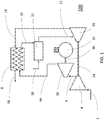
- the compressor outlet duct 6 also serves as an inlet duct to the pre-combustion turbine 30, which is operatively connected to an electrical generator 34 by a low-speed shaft 36 to transfer mechanical energy.
- the low-speed shaft 36 rotates at approximately one-quarter to one-half the rate of the high-speed shaft 24.
- Running the low-speed spool at a lower speed than the high-speed spool reduces the tip speed of the pre-combustion turbine 30, which reduces tensile stresses in the turbine components and enables manufacturing these components using lightweight materials (e.g., aluminum, titanium, polymer) to improve the turbine generator's specific power.
- the flow expands through the pre-combustion turbine 30 while generating mechanical energy, which decreases the pressure of the flow exiting through the pre-combustion turbine outlet duct 44.
- the flow's total pressure ratio between the pre-combustion turbine outlet duct 44 and the compressor outlet duct 6 is approximately two-to-three.
- the flow's pressure ratio between the pre-combustion turbine outlet duct 44 and the compressor inlet duct 2 is approximately three-to-six, in one embodiment.
- FIG. 2 is a cross-sectional diagram illustrating a two-spool turbine system with a pre-combustion turbine 30 operationally coupled to a low-speed electrical generator 34.
- a flow from the compressor inlet duct 2 enters the compressor assembly 4, where the compressor impeller 38 (e.g., a centrifugal impeller) pressurizes the flow.
- the high-speed shaft 24 operatively connects the components of the high-speed spool, including the compressor impeller 38 and the high-speed turbine impeller 88 of the high-speed turbine 16.
- the compressor impeller 38 discharges the pressurized, high-velocity flow into the compressor vaneless space 40, which serves as the compressor outlet duct 6.
- the flow enters the pre-combustion turbine impeller 42 of the pre-combustion turbine 30, where the flow expands and generates mechanical energy in the pre-combustion turbine impeller 42.
- the compressor assembly 4 powers the aerodynamically coupled pre-combustion turbine 30.
- the pre-combustion turbine impeller 42 discharges the flow through the pre-combustion turbine outlet duct 44.
- the low-speed shaft 36 operatively connects the components of the low-speed spool, including the pre-combustion turbine impeller 42 and the electrical generator 34. Locating the electrical generator 34 axially between the compressor impeller 4 and the high-speed turbine impeller 88 enhances the system's compact configuration.
- the pressurized flow enters the high-speed turbine 16 through the high-speed turbine inlet duct 22 and expands across the high-speed turbine impeller 88, generating mechanical energy for the high-speed spool.
- the high-speed turbine impeller 88 discharges the still hot flow through the high-speed turbine outlet duct 14.
- the high-speed spool may include a starter motor/generator (not illustrated) to initiate rotation of the high-speed shaft 24 when starting the two-spool turbine system 100, and/or to generate part of the electrical load during operation.
- a common bearing carrier 54 is attached to a high-speed bearing assembly 52 radially inside the common bearing carrier 54 and to a low-speed bearing assembly 56 radially outside the common bearing carrier 54.
- the high-speed bearing assembly 52 supports the high-speed shaft 24 of the high-speed spool and includes a high-speed bearing cartridge 84 fastened to the common bearing carrier 54 by a high-speed bearing retaining pin 86.
- the low-speed bearing assembly 56 supports the low-speed shaft 36 of the low-speed spool. Because of the common bearing carrier 54, the low-speed spool and the high-speed spool rotate around a common axis of rotation.
- the common bearing carrier 54 is attached to the low-speed bearing assembly 56 and the high speed-bearing assembly 52 at approximately the same axial location.
- the use of the common bearing carrier 54 beneficially enables nesting the high-speed spool radially inside the low-speed spool but at approximately the same axial location. This configuration results in a compact configuration of the two-spool turbine system
- FIG. 3 is an enlarged cross-sectional diagram illustrating the electrical generator 34 on a common low-speed spool with the pre-combustion turbine 30 of the two-spool turbine system 100.
- the electrical generator 34 is a multi-stage axial flux brushless design including coreless generator stators 62 and 66, which are secured to the housing of the system 100.
- the coreless generator stators 62 and 66 are lighter than stators with an iron core; additionally, the use of coreless stators 62 and 66 reduces audible noise by eliminating torque cogging from stator teeth.
- the electrical generator 34 also includes a rotor assembly including a front rotor 72, a middle rotor 74, and a back rotor 76.
- the rotor assembly including the permanent magnet assemblies 60, 64, and 68 and the return irons 58 and 70, is operatively coupled to the low-speed shaft 36.
- the low-speed shaft 36 turns the rotor assembly to electrically excite the coreless generator stators 62 and 66 through an axial magnetic flux.
- the number of rotors, magnet assemblies, and stators may be varied; for example, the middle permanent magnet assembly 64, middle rotor 74, and coreless generator stator 66 may be omitted or duplicated.
- the coreless generator stators 62 and 66 have a planar configuration that enables fabrication on printed circuit boards to reduce manufacturing costs.
- the electrical generator 34 may be arranged to electrically excite the electrical generator's stators through a radial magnetic flux. Such a configuration may use iron core stators in place of coreless generator stators 62 and 66.
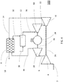
- the pressurized flow from the combustion chamber 12 enters the post-combustion turbine 80 through the post-combustion turbine inlet duct 78.
- the pressurized flow expands in the post-combustion turbine 80, which generates mechanical work transferred to the electrical generator 34.
- the post-combustion turbine 80 discharges the flow through the high-speed turbine inlet duct 22.
Landscapes
- Engineering & Computer Science (AREA)
- Mechanical Engineering (AREA)
- General Engineering & Computer Science (AREA)
- Chemical & Material Sciences (AREA)
- Combustion & Propulsion (AREA)
- Power Engineering (AREA)
- Structures Of Non-Positive Displacement Pumps (AREA)
- Connection Of Motors, Electrical Generators, Mechanical Devices, And The Like (AREA)
Claims (13)
- Générateur à turbine (100) comprenant :une chambre de combustion (12) ;une bobine à grande vitesse comprenant une turbine à grande vitesse (16) en aval de la chambre de combustion pour recevoir une puissance de celle-ci, la turbine à grande vitesse étant couplée opérationnellement à un ensemble compresseur à grande vitesse (4) en amont de la chambre de combustion ;une bobine à faible vitesse comprenant une turbine à précombustion (30) directement en amont de la chambre de combustion et directement en aval de l'ensemble compresseur à grande vitesse pour recevoir une puissance de celle-ci ;un générateur électrique (34), dans lequel le générateur électrique est situé axialement entre l'ensemble compresseur à grande vitesse et la turbine à grande vitesse, le générateur électrique comprenant un ensemble rotor couplé de manière opérationnelle à la turbine à précombustion ; etun support de palier commun (54) fixé à un ensemble palier à grande vitesse (52) supportant la bobine à grande vitesse, le support de palier commun étant fixé en outre à un ensemble palier à faible vitesse (56) supportant la bobine à faible vitesse.
- Générateur à turbine selon la revendication 1, dans lequel la bobine à grande vitesse et la bobine à faible vitesse sont agencées de sorte à avoir un axe de rotation commun.
- Générateur à turbine selon la revendication 1, dans lequel l'ensemble palier à grande vitesse est agencé radialement à l'intérieur du support de palier commun et l'ensemble palier à faible vitesse est agencé radialement à l'extérieur du support de palier commun.
- Générateur à turbine selon la revendication 1, dans lequel l'ensemble palier à grande vitesse est agencé approximativement au niveau du même emplacement axial que l'ensemble palier à faible vitesse.
- Générateur à turbine selon la revendication 1, dans lequel l'ensemble palier à grande vitesse comprend une cartouche de palier (84) attachée au support de palier commun par une tige de retenue (86).
- Générateur à turbine selon la revendication 1, dans lequel l'ensemble compresseur à grande vitesse est couplé de manière aérodynamique à la turbine à précombustion.
- Générateur à turbine selon la revendication 6, dans lequel l'ensemble compresseur à grande vitesse comprend une roue de compresseur centrifuge (38) agencée pour évacuer un écoulement d'air à grande vitesse vers la turbine à précombustion, alimentant ainsi la turbine à précombustion.
- Générateur à turbine selon la revendication 1, dans lequel la bobine à faible vitesse comprend en outre une turbine à postcombustion (80) en amont de la turbine à grande vitesse, la turbine à postcombustion étant directement en aval de la chambre de combustion pour recevoir une puissance de celle-ci.
- Générateur à turbine selon la revendication 1, dans lequel l'ensemble rotor comprend un ou plusieurs aimants permanents (60, 64, 68).
- Générateur à turbine selon la revendication 1, dans lequel le générateur électrique comprend un ou plusieurs stators (62, 66) excités électriquement par un flux magnétique axial ou radial reçu de l'ensemble rotor.
- Générateur à turbine selon la revendication 1, dans lequel le générateur électrique comprend un ou plusieurs stators de générateur sans noyau (62, 66) fabriqués sur des cartes de circuit imprimé.
- Générateur à turbine selon la revendication 1, dans lequel l'ensemble rotor est couplé de manière opérationnelle à un diffuseur rotatif en amont de la chambre de combustion et directement en aval d'une roue de compresseur (38) pour recevoir un écoulement de celui-ci.
- Générateur à turbine selon la revendication 1, dans lequel le générateur à turbine comprend en outre un diffuseur fixe en amont de la chambre de combustion et directement en aval d'une roue de compresseur (38).
Priority Applications (1)
| Application Number | Priority Date | Filing Date | Title |
|---|---|---|---|
| EP19150099.0A EP3524798A1 (fr) | 2014-03-28 | 2015-03-26 | Générateur de turbine à gaz comportant une turbine de puissance pre-combustion |
Applications Claiming Priority (2)
| Application Number | Priority Date | Filing Date | Title |
|---|---|---|---|
| US14/229,677 US9431875B2 (en) | 2014-03-28 | 2014-03-28 | Gas turbine generator with a pre-combustion power turbine |
| PCT/US2015/022823 WO2015148845A1 (fr) | 2014-03-28 | 2015-03-26 | Générateur à turbine à gaz avec une turbine de puissance à pré-combustion |
Related Child Applications (1)
| Application Number | Title | Priority Date | Filing Date |
|---|---|---|---|
| EP19150099.0A Division EP3524798A1 (fr) | 2014-03-28 | 2015-03-26 | Générateur de turbine à gaz comportant une turbine de puissance pre-combustion |
Publications (3)
| Publication Number | Publication Date |
|---|---|
| EP3123018A1 EP3123018A1 (fr) | 2017-02-01 |
| EP3123018A4 EP3123018A4 (fr) | 2017-12-27 |
| EP3123018B1 true EP3123018B1 (fr) | 2019-01-23 |
Family
ID=54189619
Family Applications (2)
| Application Number | Title | Priority Date | Filing Date |
|---|---|---|---|
| EP15767948.1A Not-in-force EP3123018B1 (fr) | 2014-03-28 | 2015-03-26 | Générateur à turbine à gaz avec une turbine de puissance à pré-combustion |
| EP19150099.0A Withdrawn EP3524798A1 (fr) | 2014-03-28 | 2015-03-26 | Générateur de turbine à gaz comportant une turbine de puissance pre-combustion |
Family Applications After (1)
| Application Number | Title | Priority Date | Filing Date |
|---|---|---|---|
| EP19150099.0A Withdrawn EP3524798A1 (fr) | 2014-03-28 | 2015-03-26 | Générateur de turbine à gaz comportant une turbine de puissance pre-combustion |
Country Status (3)
| Country | Link |
|---|---|
| US (1) | US9431875B2 (fr) |
| EP (2) | EP3123018B1 (fr) |
| WO (1) | WO2015148845A1 (fr) |
Families Citing this family (16)
| Publication number | Priority date | Publication date | Assignee | Title |
|---|---|---|---|---|
| KR102113100B1 (ko) * | 2012-09-11 | 2020-06-02 | 컨셉츠 엔알이씨, 엘엘씨 | 오버행 터빈 및 자기 베어링을 가진 발전기 시스템 |
| US20160252015A1 (en) * | 2013-11-27 | 2016-09-01 | Hitachi, Ltd. | Gas Turbine Corresponding to Renewable Energy and Control Method Therefor |
| FI127654B (en) * | 2014-05-21 | 2018-11-30 | Finno Energy Oy | System and method for generating electrical energy |
| US10612463B2 (en) * | 2015-02-09 | 2020-04-07 | Mitsubishi Heavy Industries Compressor Corporation | Gas turbine system equipped with variable speed generator connected to rotary shaft of low-pressure turbine of two-shaft gas turbine |
| US20170291712A1 (en) * | 2016-04-08 | 2017-10-12 | Hamilton Sundstrand Corporation | Hybrid electric aircraft propulsion incorporating a recuperated prime mover |
| DE102016106733A1 (de) * | 2016-04-12 | 2017-10-12 | Atlas Copco Energas Gmbh | Verfahren und Anlage zur Energieumwandlung von Druckenergie in elektrische Energie |
| US11177726B2 (en) | 2017-01-11 | 2021-11-16 | Infinitum Electric, Inc. | System and apparatus for axial field rotary energy device |
| US10141804B2 (en) | 2017-01-11 | 2018-11-27 | Infinitum Electric Inc. | System, method and apparatus for modular axial field rotary energy device |
| US10186922B2 (en) | 2017-01-11 | 2019-01-22 | Infinitum Electric Inc. | System and apparatus for axial field rotary energy device |
| WO2019190959A1 (fr) | 2018-03-26 | 2019-10-03 | Infinitum Electric Inc. | Système et appareil pour dispositif d'énergie rotatif à champ axial |
| KR20240122577A (ko) | 2018-07-10 | 2024-08-12 | 인피니텀 일렉트로닉, 아이앤씨. | 축방향 필드 회전 에너지 장치용 시스템 및 장치 |
| US11283319B2 (en) | 2019-11-11 | 2022-03-22 | Infinitum Electric, Inc. | Axial field rotary energy device with PCB stator having interleaved PCBS |
| IL272021B1 (en) * | 2020-01-13 | 2026-03-01 | Technion Res & Development Found Ltd | A generator based on an ultra-small gas turbine |
| US20210218304A1 (en) | 2020-01-14 | 2021-07-15 | Infinitum Electric, Inc. | Axial field rotary energy device having pcb stator and variable frequency drive |
| US11482908B1 (en) | 2021-04-12 | 2022-10-25 | Infinitum Electric, Inc. | System, method and apparatus for direct liquid-cooled axial flux electric machine with PCB stator |
| FR3141723B1 (fr) * | 2022-11-07 | 2024-09-20 | Psa Automobiles Sa | Vehicule automobile comprenant des turbocompresseurs multiaxiaux couples a un generateur electrique, procede sur la base d’un tel vehicule |
Family Cites Families (13)
| Publication number | Priority date | Publication date | Assignee | Title |
|---|---|---|---|---|
| US4820115A (en) * | 1987-11-12 | 1989-04-11 | Dresser Industries, Inc. | Open impeller for centrifugal compressors |
| US6073857A (en) * | 1998-09-14 | 2000-06-13 | Fairlane Tool Company | Co-generator utilizing micro gas turbine engine |
| US6606864B2 (en) * | 2001-02-13 | 2003-08-19 | Robin Mackay | Advanced multi pressure mode gas turbine |
| US6735951B2 (en) * | 2002-01-04 | 2004-05-18 | Hamilton Sundstrand Corporation | Turbocharged auxiliary power unit with controlled high speed spool |
| US7214037B2 (en) * | 2004-06-28 | 2007-05-08 | Honeywell International, Inc. | Retention of ball bearing cartridge for turbomachinery |
| KR100644966B1 (ko) * | 2004-10-19 | 2006-11-15 | 한국과학기술연구원 | 초소형 동력 발생장치 |
| JP2007074878A (ja) * | 2005-09-09 | 2007-03-22 | Toshiba Corp | 発電装置 |
| US7832938B2 (en) * | 2006-07-19 | 2010-11-16 | Mckeirnan Jr Robert D | Floating bearing cartridge for a turbocharger shaft |
| US7849669B2 (en) * | 2006-08-28 | 2010-12-14 | Rory Keogh | Turbofan engine utilizing an aerodynamically coupled pre-combustion power turbine |
| US7942635B1 (en) * | 2007-08-02 | 2011-05-17 | Florida Turbine Technologies, Inc. | Twin spool rotor assembly for a small gas turbine engine |
| US20120000204A1 (en) * | 2010-07-02 | 2012-01-05 | Icr Turbine Engine Corporation | Multi-spool intercooled recuperated gas turbine |
| GB2497365A (en) * | 2011-12-10 | 2013-06-12 | Cummins Ltd | Generator comprising a turbocharger |
| US9366432B2 (en) | 2012-05-17 | 2016-06-14 | Capstone Turbine Corporation | Multistaged lean prevaporizing premixing fuel injector |
-
2014
- 2014-03-28 US US14/229,677 patent/US9431875B2/en active Active
-
2015
- 2015-03-26 EP EP15767948.1A patent/EP3123018B1/fr not_active Not-in-force
- 2015-03-26 EP EP19150099.0A patent/EP3524798A1/fr not_active Withdrawn
- 2015-03-26 WO PCT/US2015/022823 patent/WO2015148845A1/fr not_active Ceased
Non-Patent Citations (1)
| Title |
|---|
| None * |
Also Published As
| Publication number | Publication date |
|---|---|
| EP3123018A4 (fr) | 2017-12-27 |
| EP3123018A1 (fr) | 2017-02-01 |
| WO2015148845A1 (fr) | 2015-10-01 |
| US20150275691A1 (en) | 2015-10-01 |
| US9431875B2 (en) | 2016-08-30 |
| EP3524798A1 (fr) | 2019-08-14 |
Similar Documents
| Publication | Publication Date | Title |
|---|---|---|
| EP3123018B1 (fr) | Générateur à turbine à gaz avec une turbine de puissance à pré-combustion | |
| US7721555B2 (en) | Gas turbine with free-running generator driven by by-pass gas flow | |
| US6430917B1 (en) | Single rotor turbine engine | |
| US8198744B2 (en) | Integrated boost cavity ring generator for turbofan and turboshaft engines | |
| US20090211260A1 (en) | Multi-Spool Intercooled Recuperated Gas Turbine | |
| US20080136190A1 (en) | Micro Power Generating Device | |
| EP4115059B1 (fr) | Système de génération d'énergie | |
| CA3177120C (fr) | Systeme de propulsion de turbine a gaz | |
| US20130074516A1 (en) | Gas turbines | |
| US12060827B2 (en) | Advanced 2-spool turboprop engine | |
| WO2002059469A1 (fr) | Turbine | |
| CA2426353C (fr) | Turbine a hydrogene | |
| CA3174071C (fr) | Systeme de production d'energie | |
| EP4498580A1 (fr) | Machine électrique refroidie par air | |
| KR20060010177A (ko) | 터보 제네레이터 및, 그것을 구비한 연료 전지 시스템 | |
| TR201601061A2 (tr) | Tek kullanımlık turbofan motor | |
| CZ281068B6 (cs) | Spalovací motor |
Legal Events
| Date | Code | Title | Description |
|---|---|---|---|
| STAA | Information on the status of an ep patent application or granted ep patent |
Free format text: STATUS: THE INTERNATIONAL PUBLICATION HAS BEEN MADE |
|
| PUAI | Public reference made under article 153(3) epc to a published international application that has entered the european phase |
Free format text: ORIGINAL CODE: 0009012 |
|
| STAA | Information on the status of an ep patent application or granted ep patent |
Free format text: STATUS: REQUEST FOR EXAMINATION WAS MADE |
|
| 17P | Request for examination filed |
Effective date: 20161019 |
|
| AK | Designated contracting states |
Kind code of ref document: A1 Designated state(s): AL AT BE BG CH CY CZ DE DK EE ES FI FR GB GR HR HU IE IS IT LI LT LU LV MC MK MT NL NO PL PT RO RS SE SI SK SM TR |
|
| AX | Request for extension of the european patent |
Extension state: BA ME |
|
| RAP3 | Party data changed (applicant data changed or rights of an application transferred) |
Owner name: SCALED POWER CORP. |
|
| RIN1 | Information on inventor provided before grant (corrected) |
Inventor name: KEOGH, RORY, C. Inventor name: THOMAS, GREGORY |
|
| DAV | Request for validation of the european patent (deleted) | ||
| DAX | Request for extension of the european patent (deleted) | ||
| A4 | Supplementary search report drawn up and despatched |
Effective date: 20171124 |
|
| RIC1 | Information provided on ipc code assigned before grant |
Ipc: F02C 3/10 20060101ALI20171120BHEP Ipc: F01D 15/10 20060101ALI20171120BHEP Ipc: F02C 1/02 20060101ALI20171120BHEP Ipc: F02C 7/36 20060101AFI20171120BHEP |
|
| GRAP | Despatch of communication of intention to grant a patent |
Free format text: ORIGINAL CODE: EPIDOSNIGR1 |
|
| STAA | Information on the status of an ep patent application or granted ep patent |
Free format text: STATUS: GRANT OF PATENT IS INTENDED |
|
| RIC1 | Information provided on ipc code assigned before grant |
Ipc: F02C 7/36 20060101AFI20180627BHEP Ipc: F02C 1/02 20060101ALI20180627BHEP Ipc: H02K 7/18 20060101ALI20180627BHEP Ipc: F02C 3/073 20060101ALI20180627BHEP Ipc: F01D 15/10 20060101ALI20180627BHEP Ipc: F02C 3/10 20060101ALI20180627BHEP |
|
| INTG | Intention to grant announced |
Effective date: 20180731 |
|
| GRAS | Grant fee paid |
Free format text: ORIGINAL CODE: EPIDOSNIGR3 |
|
| GRAA | (expected) grant |
Free format text: ORIGINAL CODE: 0009210 |
|
| STAA | Information on the status of an ep patent application or granted ep patent |
Free format text: STATUS: THE PATENT HAS BEEN GRANTED |
|
| AK | Designated contracting states |
Kind code of ref document: B1 Designated state(s): AL AT BE BG CH CY CZ DE DK EE ES FI FR GB GR HR HU IE IS IT LI LT LU LV MC MK MT NL NO PL PT RO RS SE SI SK SM TR |
|
| REG | Reference to a national code |
Ref country code: GB Ref legal event code: FG4D |
|
| REG | Reference to a national code |
Ref country code: CH Ref legal event code: EP |
|
| REG | Reference to a national code |
Ref country code: AT Ref legal event code: REF Ref document number: 1091636 Country of ref document: AT Kind code of ref document: T Effective date: 20190215 |
|
| REG | Reference to a national code |
Ref country code: IE Ref legal event code: FG4D |
|
| REG | Reference to a national code |
Ref country code: DE Ref legal event code: R096 Ref document number: 602015023706 Country of ref document: DE |
|
| REG | Reference to a national code |
Ref country code: NL Ref legal event code: FP |
|
| REG | Reference to a national code |
Ref country code: DE Ref legal event code: R082 Ref document number: 602015023706 Country of ref document: DE Representative=s name: SPLANEMANN PATENTANWAELTE PARTNERSCHAFT MBB, DE |
|
| PG25 | Lapsed in a contracting state [announced via postgrant information from national office to epo] |
Ref country code: ES Free format text: LAPSE BECAUSE OF FAILURE TO SUBMIT A TRANSLATION OF THE DESCRIPTION OR TO PAY THE FEE WITHIN THE PRESCRIBED TIME-LIMIT Effective date: 20190123 Ref country code: PT Free format text: LAPSE BECAUSE OF FAILURE TO SUBMIT A TRANSLATION OF THE DESCRIPTION OR TO PAY THE FEE WITHIN THE PRESCRIBED TIME-LIMIT Effective date: 20190523 Ref country code: SE Free format text: LAPSE BECAUSE OF FAILURE TO SUBMIT A TRANSLATION OF THE DESCRIPTION OR TO PAY THE FEE WITHIN THE PRESCRIBED TIME-LIMIT Effective date: 20190123 Ref country code: PL Free format text: LAPSE BECAUSE OF FAILURE TO SUBMIT A TRANSLATION OF THE DESCRIPTION OR TO PAY THE FEE WITHIN THE PRESCRIBED TIME-LIMIT Effective date: 20190123 Ref country code: NO Free format text: LAPSE BECAUSE OF FAILURE TO SUBMIT A TRANSLATION OF THE DESCRIPTION OR TO PAY THE FEE WITHIN THE PRESCRIBED TIME-LIMIT Effective date: 20190423 Ref country code: LT Free format text: LAPSE BECAUSE OF FAILURE TO SUBMIT A TRANSLATION OF THE DESCRIPTION OR TO PAY THE FEE WITHIN THE PRESCRIBED TIME-LIMIT Effective date: 20190123 Ref country code: FI Free format text: LAPSE BECAUSE OF FAILURE TO SUBMIT A TRANSLATION OF THE DESCRIPTION OR TO PAY THE FEE WITHIN THE PRESCRIBED TIME-LIMIT Effective date: 20190123 |
|
| REG | Reference to a national code |
Ref country code: AT Ref legal event code: MK05 Ref document number: 1091636 Country of ref document: AT Kind code of ref document: T Effective date: 20190123 |
|
| PG25 | Lapsed in a contracting state [announced via postgrant information from national office to epo] |
Ref country code: BG Free format text: LAPSE BECAUSE OF FAILURE TO SUBMIT A TRANSLATION OF THE DESCRIPTION OR TO PAY THE FEE WITHIN THE PRESCRIBED TIME-LIMIT Effective date: 20190423 Ref country code: RS Free format text: LAPSE BECAUSE OF FAILURE TO SUBMIT A TRANSLATION OF THE DESCRIPTION OR TO PAY THE FEE WITHIN THE PRESCRIBED TIME-LIMIT Effective date: 20190123 Ref country code: HR Free format text: LAPSE BECAUSE OF FAILURE TO SUBMIT A TRANSLATION OF THE DESCRIPTION OR TO PAY THE FEE WITHIN THE PRESCRIBED TIME-LIMIT Effective date: 20190123 Ref country code: IS Free format text: LAPSE BECAUSE OF FAILURE TO SUBMIT A TRANSLATION OF THE DESCRIPTION OR TO PAY THE FEE WITHIN THE PRESCRIBED TIME-LIMIT Effective date: 20190523 Ref country code: LV Free format text: LAPSE BECAUSE OF FAILURE TO SUBMIT A TRANSLATION OF THE DESCRIPTION OR TO PAY THE FEE WITHIN THE PRESCRIBED TIME-LIMIT Effective date: 20190123 Ref country code: GR Free format text: LAPSE BECAUSE OF FAILURE TO SUBMIT A TRANSLATION OF THE DESCRIPTION OR TO PAY THE FEE WITHIN THE PRESCRIBED TIME-LIMIT Effective date: 20190424 |
|
| REG | Reference to a national code |
Ref country code: DE Ref legal event code: R097 Ref document number: 602015023706 Country of ref document: DE |
|
| PG25 | Lapsed in a contracting state [announced via postgrant information from national office to epo] |
Ref country code: RO Free format text: LAPSE BECAUSE OF FAILURE TO SUBMIT A TRANSLATION OF THE DESCRIPTION OR TO PAY THE FEE WITHIN THE PRESCRIBED TIME-LIMIT Effective date: 20190123 Ref country code: SK Free format text: LAPSE BECAUSE OF FAILURE TO SUBMIT A TRANSLATION OF THE DESCRIPTION OR TO PAY THE FEE WITHIN THE PRESCRIBED TIME-LIMIT Effective date: 20190123 Ref country code: AL Free format text: LAPSE BECAUSE OF FAILURE TO SUBMIT A TRANSLATION OF THE DESCRIPTION OR TO PAY THE FEE WITHIN THE PRESCRIBED TIME-LIMIT Effective date: 20190123 Ref country code: DK Free format text: LAPSE BECAUSE OF FAILURE TO SUBMIT A TRANSLATION OF THE DESCRIPTION OR TO PAY THE FEE WITHIN THE PRESCRIBED TIME-LIMIT Effective date: 20190123 Ref country code: MC Free format text: LAPSE BECAUSE OF FAILURE TO SUBMIT A TRANSLATION OF THE DESCRIPTION OR TO PAY THE FEE WITHIN THE PRESCRIBED TIME-LIMIT Effective date: 20190123 Ref country code: EE Free format text: LAPSE BECAUSE OF FAILURE TO SUBMIT A TRANSLATION OF THE DESCRIPTION OR TO PAY THE FEE WITHIN THE PRESCRIBED TIME-LIMIT Effective date: 20190123 |
|
| REG | Reference to a national code |
Ref country code: CH Ref legal event code: PL |
|
| PG25 | Lapsed in a contracting state [announced via postgrant information from national office to epo] |
Ref country code: LU Free format text: LAPSE BECAUSE OF NON-PAYMENT OF DUE FEES Effective date: 20190326 Ref country code: SM Free format text: LAPSE BECAUSE OF FAILURE TO SUBMIT A TRANSLATION OF THE DESCRIPTION OR TO PAY THE FEE WITHIN THE PRESCRIBED TIME-LIMIT Effective date: 20190123 |
|
| PLBE | No opposition filed within time limit |
Free format text: ORIGINAL CODE: 0009261 |
|
| REG | Reference to a national code |
Ref country code: BE Ref legal event code: MM Effective date: 20190331 |
|
| STAA | Information on the status of an ep patent application or granted ep patent |
Free format text: STATUS: NO OPPOSITION FILED WITHIN TIME LIMIT |
|
| PG25 | Lapsed in a contracting state [announced via postgrant information from national office to epo] |
Ref country code: AT Free format text: LAPSE BECAUSE OF FAILURE TO SUBMIT A TRANSLATION OF THE DESCRIPTION OR TO PAY THE FEE WITHIN THE PRESCRIBED TIME-LIMIT Effective date: 20190123 |
|
| 26N | No opposition filed |
Effective date: 20191024 |
|
| PG25 | Lapsed in a contracting state [announced via postgrant information from national office to epo] |
Ref country code: LI Free format text: LAPSE BECAUSE OF NON-PAYMENT OF DUE FEES Effective date: 20190331 Ref country code: IE Free format text: LAPSE BECAUSE OF NON-PAYMENT OF DUE FEES Effective date: 20190326 Ref country code: CH Free format text: LAPSE BECAUSE OF NON-PAYMENT OF DUE FEES Effective date: 20190331 |
|
| PG25 | Lapsed in a contracting state [announced via postgrant information from national office to epo] |
Ref country code: SI Free format text: LAPSE BECAUSE OF FAILURE TO SUBMIT A TRANSLATION OF THE DESCRIPTION OR TO PAY THE FEE WITHIN THE PRESCRIBED TIME-LIMIT Effective date: 20190123 Ref country code: BE Free format text: LAPSE BECAUSE OF NON-PAYMENT OF DUE FEES Effective date: 20190331 |
|
| PG25 | Lapsed in a contracting state [announced via postgrant information from national office to epo] |
Ref country code: TR Free format text: LAPSE BECAUSE OF FAILURE TO SUBMIT A TRANSLATION OF THE DESCRIPTION OR TO PAY THE FEE WITHIN THE PRESCRIBED TIME-LIMIT Effective date: 20190123 |
|
| PG25 | Lapsed in a contracting state [announced via postgrant information from national office to epo] |
Ref country code: MT Free format text: LAPSE BECAUSE OF NON-PAYMENT OF DUE FEES Effective date: 20190326 |
|
| PG25 | Lapsed in a contracting state [announced via postgrant information from national office to epo] |
Ref country code: CY Free format text: LAPSE BECAUSE OF FAILURE TO SUBMIT A TRANSLATION OF THE DESCRIPTION OR TO PAY THE FEE WITHIN THE PRESCRIBED TIME-LIMIT Effective date: 20190123 |
|
| PG25 | Lapsed in a contracting state [announced via postgrant information from national office to epo] |
Ref country code: HU Free format text: LAPSE BECAUSE OF FAILURE TO SUBMIT A TRANSLATION OF THE DESCRIPTION OR TO PAY THE FEE WITHIN THE PRESCRIBED TIME-LIMIT; INVALID AB INITIO Effective date: 20150326 |
|
| PG25 | Lapsed in a contracting state [announced via postgrant information from national office to epo] |
Ref country code: MK Free format text: LAPSE BECAUSE OF FAILURE TO SUBMIT A TRANSLATION OF THE DESCRIPTION OR TO PAY THE FEE WITHIN THE PRESCRIBED TIME-LIMIT Effective date: 20190123 |
|
| PGFP | Annual fee paid to national office [announced via postgrant information from national office to epo] |
Ref country code: NL Payment date: 20240725 Year of fee payment: 10 |
|
| PGFP | Annual fee paid to national office [announced via postgrant information from national office to epo] |
Ref country code: DE Payment date: 20240723 Year of fee payment: 10 |
|
| PGFP | Annual fee paid to national office [announced via postgrant information from national office to epo] |
Ref country code: GB Payment date: 20240725 Year of fee payment: 10 |
|
| PGFP | Annual fee paid to national office [announced via postgrant information from national office to epo] |
Ref country code: FR Payment date: 20240726 Year of fee payment: 10 |
|
| PGFP | Annual fee paid to national office [announced via postgrant information from national office to epo] |
Ref country code: CZ Payment date: 20240726 Year of fee payment: 10 |
|
| PGFP | Annual fee paid to national office [announced via postgrant information from national office to epo] |
Ref country code: IT Payment date: 20240726 Year of fee payment: 10 |
|
| REG | Reference to a national code |
Ref country code: DE Ref legal event code: R119 Ref document number: 602015023706 Country of ref document: DE |
|
| PG25 | Lapsed in a contracting state [announced via postgrant information from national office to epo] |
Ref country code: CZ Free format text: LAPSE BECAUSE OF NON-PAYMENT OF DUE FEES Effective date: 20250326 |
|
| REG | Reference to a national code |
Ref country code: NL Ref legal event code: MM Effective date: 20250401 |
|
| GBPC | Gb: european patent ceased through non-payment of renewal fee |
Effective date: 20250326 |
|
| PG25 | Lapsed in a contracting state [announced via postgrant information from national office to epo] |
Ref country code: NL Free format text: LAPSE BECAUSE OF NON-PAYMENT OF DUE FEES Effective date: 20250401 |
|
| PG25 | Lapsed in a contracting state [announced via postgrant information from national office to epo] |
Ref country code: DE Free format text: LAPSE BECAUSE OF NON-PAYMENT OF DUE FEES Effective date: 20251001 |
|
| PG25 | Lapsed in a contracting state [announced via postgrant information from national office to epo] |
Ref country code: GB Free format text: LAPSE BECAUSE OF NON-PAYMENT OF DUE FEES Effective date: 20250326 |
|
| PG25 | Lapsed in a contracting state [announced via postgrant information from national office to epo] |
Ref country code: FR Free format text: LAPSE BECAUSE OF NON-PAYMENT OF DUE FEES Effective date: 20250331 Ref country code: IT Free format text: LAPSE BECAUSE OF NON-PAYMENT OF DUE FEES Effective date: 20250326 |