EP3123116B1 - Affichage tête haute - Google Patents
Affichage tête haute Download PDFInfo
- Publication number
- EP3123116B1 EP3123116B1 EP15712168.2A EP15712168A EP3123116B1 EP 3123116 B1 EP3123116 B1 EP 3123116B1 EP 15712168 A EP15712168 A EP 15712168A EP 3123116 B1 EP3123116 B1 EP 3123116B1
- Authority
- EP
- European Patent Office
- Prior art keywords
- aircraft
- fpm
- display
- camera
- pilot
- Prior art date
- Legal status (The legal status is an assumption and is not a legal conclusion. Google has not performed a legal analysis and makes no representation as to the accuracy of the status listed.)
- Not-in-force
Links
Images





Classifications
-
- G—PHYSICS
- G08—SIGNALLING
- G08G—TRAFFIC CONTROL SYSTEMS
- G08G5/00—Traffic control systems for aircraft
- G08G5/20—Arrangements for acquiring, generating, sharing or displaying traffic information
- G08G5/21—Arrangements for acquiring, generating, sharing or displaying traffic information located onboard the aircraft
-
- B—PERFORMING OPERATIONS; TRANSPORTING
- B64—AIRCRAFT; AVIATION; COSMONAUTICS
- B64D—EQUIPMENT FOR FITTING IN OR TO AIRCRAFT; FLIGHT SUITS; PARACHUTES; ARRANGEMENT OR MOUNTING OF POWER PLANTS OR PROPULSION TRANSMISSIONS IN AIRCRAFT
- B64D43/00—Arrangements or adaptations of instruments
-
- G—PHYSICS
- G01—MEASURING; TESTING
- G01C—MEASURING DISTANCES, LEVELS OR BEARINGS; SURVEYING; NAVIGATION; GYROSCOPIC INSTRUMENTS; PHOTOGRAMMETRY OR VIDEOGRAMMETRY
- G01C23/00—Combined instruments indicating more than one navigational value, e.g. for aircraft; Combined measuring devices for measuring two or more variables of movement, e.g. distance, speed or acceleration
-
- G—PHYSICS
- G06—COMPUTING OR CALCULATING; COUNTING
- G06T—IMAGE DATA PROCESSING OR GENERATION, IN GENERAL
- G06T11/00—Two-dimensional [2D] image generation
- G06T11/60—Creating or editing images; Combining images with text
-
- G—PHYSICS
- G06—COMPUTING OR CALCULATING; COUNTING
- G06T—IMAGE DATA PROCESSING OR GENERATION, IN GENERAL
- G06T11/00—Two-dimensional [2D] image generation
- G06T11/60—Creating or editing images; Combining images with text
- G06T11/65—Creating or editing images; Combining images with text on geographic maps
-
- G—PHYSICS
- G06—COMPUTING OR CALCULATING; COUNTING
- G06T—IMAGE DATA PROCESSING OR GENERATION, IN GENERAL
- G06T7/00—Image analysis
- G06T7/20—Analysis of motion
-
- G—PHYSICS
- G06—COMPUTING OR CALCULATING; COUNTING
- G06T—IMAGE DATA PROCESSING OR GENERATION, IN GENERAL
- G06T7/00—Image analysis
- G06T7/60—Analysis of geometric attributes
-
- G—PHYSICS
- G06—COMPUTING OR CALCULATING; COUNTING
- G06T—IMAGE DATA PROCESSING OR GENERATION, IN GENERAL
- G06T7/00—Image analysis
- G06T7/70—Determining position or orientation of objects or cameras
-
- G—PHYSICS
- G06—COMPUTING OR CALCULATING; COUNTING
- G06T—IMAGE DATA PROCESSING OR GENERATION, IN GENERAL
- G06T2207/00—Indexing scheme for image analysis or image enhancement
- G06T2207/30—Subject of image; Context of image processing
- G06T2207/30204—Marker
Definitions
- a head-up display system and method there is disclosed a head-up display system and method.
- a portable head-up display system and method for an aircraft including a display, a camera and a processor.
- a head-up display is a transparent display that provides data in the normal viewing direction of the pilot. The pilot is not required to look down to see instruments as the display shows the information on the transparent screen.
- HUDs are found in military aircraft, although more recently they have been introduced in large commercial aircraft.
- HUD head-up display
- FPM flight path marker
- the main advantage of a HUD is the provision of a FPM which enables a pilot to appreciate where the aircraft is flying towards when no further steering input is given.
- the FPM is especially useful during difficult landings where crosswinds or poor visibility make it particularly difficult to determine where the aircraft is flying towards, and often different to where it is physically pointing (i.e. the direction of its longitudinal axis).
- a conventional head up display solves this by projecting numerous types of information onto a transparent surface in the pilot's field of view through the cockpit window. Because the information is projected on a transparent surface, it possible for the pilot to look through the HUD while observing the required information and while still looking directly out of the cockpit window.
- a conventional HUD includes a projector unit, a combiner and a computer. The projector projects the information onto the combiner which is typically a glass plate. The computer receives information from the aircraft instrumentation and using the data generates imagery and symbology to send to the projector for projection onto the combiner.
- HUD One of the basic features a HUD provides is the current attitude of the aircraft relative to the earth's horizon. It shows how much the aircraft is banking and whether the aircraft is climbing or descending. It can also be used to check if the aircraft is no longer banking and/or climbing or descending, making it possible to keep the aircraft level.
- Other basic information that can be displayed on a HUD is information such as the airspeed, altitude and heading. A HUD can gain this information for example from a connection with the conventional instruments or from an Inertial Reference System (IRS), which is a system that measures the force vectors of the aircraft to determine information such as movement around the aircraft's orthogonal axes.
- IRS Inertial Reference System
- the HUD is able to display new features that assist the pilot, including the FPM, typically displayed as a circle with two or three lines.
- the FPM uses the force vectors of the aircraft to determine where the aircraft would end up when no further input to the flight controls would be made. By keeping the FPM pointed at a certain point the pilot knows that the aircraft will end up at that particular point, subject to any changes the pilot decides upon, or changing external environmental conditions. This makes navigating the aircraft far easier and safer.
- the FPM is especially useful during landings or when flying through mountainous terrain. For example during landing, the only thing the pilot needs to do is to keep aiming the FPM on the threshold of the runway.
- the aircraft When doing so, the aircraft will end up right at the threshold of the runway. If the aircraft is flying at a low altitude in mountainous terrain, if the FPM is aiming at a mountain the pilot will instantaneously know that the aircraft is heading towards that mountain and the pilot can take corrective action to avoid a collision.
- the force-vectors of the aircraft from the IRS are used to determine where the aircraft is going in order to display the FPM. Because a FPM is determined from the force vectors it is also helpful in complex flight situations such as crosswind landings because it may not be immediately apparent how much a crosswind is affecting the flight path.
- a HUD is a relatively new and uncommon technology and is not normally used in aircraft in the CS-23 EASA certification category (i.e. normal, utility, aerobatic and commuter aeroplanes) due to the prohibitive cost of HUDs. Furthermore, new products for aircraft are subject to complex and costly certification processes which cause difficulty for new products to make it to the marketplace due to lack of certification from regulators.
- a portable head up display system for an aircraft comprising:
- the advantage of the portable head-up display (PHUD) system is that the system provides means for calculating a flight path marker from two different measurement systems.
- the first flight path marker (FPM I ) is calculated from avionic information from the instrumentation, either of the aircraft or of the system and the second flight path marker (FPM O ) is calculated using information derived from the flow of pixels in successive images captured by the camera.
- the head-up display system provides redundancy of the flight path marker because the displayed flight path marker is calculated using independent components that operate in parallel. If the correlation between FPM I and FPM O indicate a lack of correspondence greater than a predetermined threshold, an alarm is triggered informing the pilot that there is a problem with either one of the calculations and as such the flight path marker should not be used.
- a focus of expansion (FOE) of the flow of pixels over a time period (t i ) may be determined by the processor, the FPM O being determined on the basis of the position of the FOE.
- the FPM O may be determined from an adjustment of the position of the FOE based on pitch, roll and/or yaw motion of the aircraft, said motion of the aircraft being determined by computation of at least one reference point of said flow of pixels over said time period.
- the processor may be adapted to compute a centre of motion (COM) of said flow of pixels over said time period.
- COM centre of motion
- the COM may be determined based on goniometric determinations from pixel flow over said period.
- the processor may be adapted to overlay, on the image displayed by the display, at least one of: a bank angle indicator; a slip angle indicator, the slip angle being derived by the processor using the instrumentation; a maximum angle of attack (MAOA) indicator an airspeed indicator; an altitude indicator; a horizon line indicator; a heading indicator; or an acceleration indicator.
- a bank angle indicator e.g., a bank angle indicator
- a slip angle indicator e.g., the slip angle of the slip angle being derived by the processor using the instrumentation
- MAOA maximum angle of attack
- the processor may be adapted to overlay, on the image displayed by the display, at least one of: a bank angle indicator; a slip angle indicator, the slip angle being derived by the processor using the instrumentation; a maximum angle of attack (MAOA) indicator an airspeed indicator; an altitude indicator; a horizon line indicator; a heading indicator; or an acceleration indicator.
- MAOA maximum angle of attack
- the instrumentation may include an inertial measurement unit (IMU).
- IMU inertial measurement unit
- the instrumentation may include a global positioning system (GPS), a microelectromechanical system gyroscope (MEMS gyro) and/or an accelerometer.
- GPS global positioning system
- MEMS gyro microelectromechanical system gyroscope
- accelerometer an accelerometer
- the instrumentation may be provided in a tamper-proof housing, and optionally, the tamper-proof housing is provided with an integral power supply.
- a method for using a portable head-up display in an aircraft comprising:
- the method may further comprise:
- the method may further comprise identifying on the basis of flow of pixels in successive images captured by the camera the centre of motion (COM) of the aircraft using goniometric determinations.
- COM centre of motion
- the method may further comprise:
- the method may further comprise:
- Figure 1 shows a display 10 such as a tablet computer of a portable head up display system 2.
- the display is positioned in a cockpit of an aircraft in a forward line of sight of a pilot when seated in a pilot's seat in the cockpit.
- the display is held in position using a frame and brackets (not shown) connected to the cockpit.
- Alternative fixing means such as a hook and loop fasteners, or other fixing means known in the art may be used to fix the display in the cockpit.
- a camera is positioned on the aircraft to provide a field of view that at least partially intersects the line of sight of the pilot when seated in the pilot's seat in the cockpit.
- the camera is attached towards the front of the aircraft.
- the available field of view of the camera will be dependent on the type of camera used. Typically, a high definition camera is used to capture successive images.
- Cameras may be positioned on the underside of the aircraft, as well as on the port and starboard sides of the aircraft.
- a camera may also be positioned at the rear of the aircraft. The exact location of the camera, or cameras, will depend upon the type of aircraft the head-up display system is adapted for.
- a ground view camera may be provided for disposition on the aircraft to provide a field of view of the ground.
- a rear view camera may be provided for disposition on the aircraft to provide a field of view of the view from the rear of the aircraft.
- the processor is preferably housed in a secure and robust housing 20 having controls 22 for operating the processor.
- the processor connects to either the aircraft's instrumentation or it connects to standalone instrumentation within the housing.
- the housing is fed pressure related data via connection ports 24 from the aircraft's own instrumentation relating to ground speed and altitude.
- the processor connects to the tablet via wired or wireless connections 26.
- the blue box (or housing 20) has access to or determines air data, navigation data, engine data, sonar altitude, outside air temperature (OAT), audio data and video data from the camera.
- Suitable connections 24 are provided to access such data from aircraft systems (as well as from the camera (not shown)).
- the blue box 20 may include suitable instrumentation to determine such data for itself.
- said connections may include connections for relevant sensors, such as external air pressure, from which to make the requisite determinations.
- the processor uses the information from the instrumentation to push the processed data to the display for display.
- data pushed to the display for display on the display includes successive images (i.e. video images) from the camera, altitude, pitch ladder, the horizon line, maximum angle of attack (MAOA), bank angle and slip.
- the processor calculates a flight path marker for display on the display.
- the processor calculates, on the basis of the avionic information from the instrumentation, a first flight path marker (FPM I ) based on avionic information from inertial measurements.
- the FPM I is an instantaneous calculation, irrespective of historic or future movements. It is updated as frequently as desired based on the force vectors currently applying to the aircraft at any instant.
- An FPM is an extremely useful piece of information for a pilot, on which significant reliance may be placed when it is provided on a HUD. Research has indicated that multiple aircraft accidents where pilot error accounted at least in part for the cause of the accident could potentially have been avoided if the aircraft had had a HUD with an FPM. Because of this usefulness and potential reliance placed upon it by pilot's, some assurance or checking needs to be provided that the FPM displayed is correct.
- the processor also receives successive images captured by the camera, and calculates, on the basis of flow of pixels in successive images a second flight path marker (FPM O ), to correlate with the FPM I .
- FPM O flight path marker
- the pilot In a CS-23 category aircraft, the pilot is always able to view a panel showing a number of gauges displaying data from the inertial measurement system, and from which FPM I can be determined with appropriate calculations.
- the panel is usually positioned away from the cockpit window forcing the pilot to break his or her view and look away from the cockpit window in order to see the panel and access the data.
- the second flight path marker (FPM O ) is calculated based on a principle of optical flow.
- Optical flow (OF) is the movement or flow of pixels across a series of successive images captured by a moving camera. By analysing the OF, it is possible to determine the focus of expansion (FOE) of an image.
- the FOE is the point from which all pixel vectors are radially expanding. Therefore the FOE corresponds to the point where the camera (or aircraft) is traveling towards.
- the movement of the aircraft with respect to time is determined and the second flight path marker (FPM O ) is calculated.
- the calculation of the FPM O is completely independent of the calculation of the first flight path marker (FPM I ) and therefore provides redundancy for this aspect of the head up display system.
- Figure 1 shows an example of the display (such as a tablet computer display) with data overlaid on the display including a portion of the field of view 12 of the camera, a flight path marker 50 and other data 52.
- the second flight path marker (FPM O ) is calculated based on a principle of optical flow.
- OF is typically processed by tracking points with a constant brightness. This is based on the assumption that the brightness of a point in the scene stays constant over a far greater timescale than the timescale between successive images. Therefore, the optical flow only relates to movement of the aircraft.
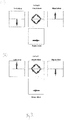
- Figures 2 , 3(a) and 3(b) show the expected optical flow patterns for different translations and rotations of the aircraft.
- Figure 2 corresponds to the expected flow field of pixels when the aircraft (and camera) is moving forward.
- Figure 2 shows either portions of an image from a wide-angle camera, one that not only has a field of view in a forward direction, but also left, right and down.
- Figure 2 is a composition of images from four different camera units, pointing forward, left, right and down. In either case, the movement of pixels is the same, depending on the direction of a particular pixel with respect to the camera's movement.
- Figures 3(a) and 3(b) show the expected flow field of pixels when the aircraft is rolling to the right and rolling to the left respectively.
- mapping the expected OF field for a particular aircraft movement it is possible to identify and calculate the movement of the aircraft by analysing the recorded OF fields.
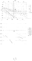
- Figure 4 shows the pixel flow field for 6 tracked pixels, the pixels having been tracked between successive images captured by the camera.
- the FPM shown on Figure 4 was obtained directly from the flight-simulator program.
- a number of pixels were tracked for a plurality of time steps and the linear trend lines between the pixel coordinates are shown at the top of the figure. From the linear trend lines, the FOE is extrapolated, the FOE corresponding with the FPM O .
- the determination of the FPM O is particularly accurate in the forward direction as shown in Figure 4 . However, this is not the case for all movements of the aircraft.
- Figures 5 and 6 show the pixel flow field for 6 tracked pixels as before.
- the FOE is located outside of the field of view of the camera and a correction is needed to identify the FPM.
- COM centre of motion
- yaw or pitch if the turn is continued at the same turn angle, it is possible to predict where the aircraft will head at some future time, whereas the FPM is the point the aircraft is flying towards at a particular instant and if the turn was instantly removed.
- the COM is the point towards which the aircraft is flying, as shown in Figure 3 .
- reference pixels When the aircraft is yawing, (or pitching or rolling) reference pixels may be used to adjust the apparent FOE using the flow of reference pixels between successive images over a time period (t i ).
- Reference pixels are identified in an image and may correspond to the horizon line, or a feature such as a distant building or the summit of a peak. In certain situations, other slow moving or stationary identifiable reference pixels may be used to adjust the FOE.
- a predetermined set of criteria is applied in order to identify a reference pixel in the image and the identified reference pixel is then tracked between successive images.
- An adjustment factor is computed by the processor to adjust the FOE for the effects of pitch, roll and/or yaw motion of the aircraft.
- the adjustment factor is applied to the FOE to correct the FPM O .
- Figures 7a and 7b show the successive images captured during roll of the aircraft. Successive images have been superimposed without any adjustment in Figure 7a .
- certain points have been identified in the images.
- the reference points correspond to the medium sized building 60, the large shopping complex 62 and the small building 64 are shown in the Figure.
- the buildings are offset (between 60 and 60') not only by the forward translational movement of the aircraft but also due to the roll of the aircraft in the time between image capture.
- Figure 7a shows an unadjusted set of superimposed images.
- the flow of pixels corresponding to the reference points without applying any adjustment factor is shown in the form of extrapolated flow lines (see for example, for each building 60, 62 and 64, the flow lines 60", 62" and 64") between the reference points between successive images.
- the extrapolated flow lines do not correspond to the FOE.
- the FOE is adjusted by first identifying the horizon and overlaying the identified horizon of successive images. This stabilises the effect of the roll of the aircraft and enables the calculation of the adjusted FOE and therefore the determination of the FPM o . It is clear from Figure 7b that by stabilising the images using the reference of the horizon (at least one corresponding reference pixel), from the flow of pixels between successive images it is possible to identify a FOE and therefore identify a FPM O . Simply overlaying the horizon of successive images provides clear determination of the FOE and the FPM O .
- the horizon is identified and successive images are overlaid using the point of reference (i.e. the horizon) to effectively stabilise the effect of the pitch of the aircraft and enables the calculation of the adjusted FOE and therefore the determination of the FPM o .
- the situation is subtly different for yaw motion of the aircraft.
- the horizon does not provide a means of stabilising the images.
- reference points of buildings may be used to stabilise the images.
- the reference pixels identified include reference points such as buildings or summits of mountains or other identifiable pixels. Using reference pixels, successive images may be stabilised for yaw motion.
- the flow of pixels may also be used to determine the amount of displacement of the aircraft over and around a particular axis. From this information, it is possible to predict where the aircraft is turning towards, and the current FPM, of course. This information is not provided by the FPM I , since it only gives instantaneous information on the direction of aircraft heading. It is possible to choose not to take this COM information into account, or to use it as a kind of predictor (rate of pitch, and rate of turn rate of roll etc). It is to be noted, that as a practical matter, at least during flight, there will always be an FOE because the aircraft will always translate in some direction and not only rotate about an axis, as suggested in Figure 6 , for example.
- goniometric calculations may be used to identify the distance ⁇ x the aircraft has travelled by mapping pixels in the field of view of the camera and by using the distance h from the earth's surface to the aircraft and the angle of view of the camera as shown in Figure 7(a) .
- the processor calculates a dimension of rotation of the aircraft by knowing the angle of view of the camera.
- a raster of successive images from the camera is developed and knowing the distance from the aircraft to the ground, or to an object such as a distant mountain (for example, using radar), it is feasible to calculate an effective ground distance the aircraft has travelled between two successive images.
- At least two ground coordinates from successive images from the camera may be identified, the ground coordinates providing a time sequenced indication of ground position of the aircraft.
- a calculation can then be made of the angle between the two ground coordinates, the angle representing an angle of rotation of the aircraft and the centre of motion (COM) of the aircraft.
- COM centre of motion
- the processor overlays the calculated flight path marker on the image displayed by the display.
- the displayed flight path marker may be one of either the first and second flight path markers (i.e. either FPM I or FPM O ), or a combination thereof.
- An alarm is provided if the correlation between the first and second flight path markers is less than a predetermined threshold.
- the alarm may be a sound, a flashing light, or a change in the displayed flight path marker and the alarm indicates a lack of correspondence between FPM I and FPM O .
- the alarm provides the pilot with a warning that either the FPM I or FPM O are not functioning effectively, or therefore neither the FPM I nor FPM O should be relied upon for navigation.
- head-up display system Although embodiments of the head-up display system are described in relation to an aircraft it is envisaged that the head-up display system is equally adaptable for use in other modes of transport such as automobiles, ships, boats, and military tanks.
- the head-up display system is adaptable for incorporation into a wearable device such as a helmet.
Landscapes
- Engineering & Computer Science (AREA)
- Physics & Mathematics (AREA)
- General Physics & Mathematics (AREA)
- Theoretical Computer Science (AREA)
- Aviation & Aerospace Engineering (AREA)
- Radar, Positioning & Navigation (AREA)
- Remote Sensing (AREA)
- Computer Vision & Pattern Recognition (AREA)
- Multimedia (AREA)
- Geometry (AREA)
- Traffic Control Systems (AREA)
- Navigation (AREA)
Claims (14)
- Système d'affichage tête haute portatif (2) pour un aéronef comprenant :un dispositif d'affichage (10), destiné à être disposé dans un poste de pilotage de l'aéronef selon une ligne de mire avant d'un pilote lorsque ce dernier est assis dans un siège de pilote dans le poste de pilotage ;une caméra, destinée à être disposée sur l'aéronef afin de fournir un champ de vision (12) qui croise au moins partiellement la ligne de mire du pilote lorsque ce dernier est assis dans le siège du pilote dans le poste de pilotage ; etun processeur ; ledit dispositif d'affichage (10) pouvant être configuré pour afficher une image capturée par la caméra de l'environnement extérieur de l'aéronef que le pilote observerait dans la direction du dispositif d'affichage, en l'absence du dispositif d'affichage et de tout objet de l'aéronef ;ledit processeur étant adapté pour recevoir des informations avioniques provenant de l'instrumentation, soit de l'aéronef soit du système ;ledit processeur étant adapté pour calculer, sur la base de l'instrumentation, un premier marqueur de trajectoire de vol (FPMI) ; caractérisé en ce que le processeur est adapté pour calculer, sur la base du flux de pixels dans des images successives capturées par la caméra, un second marqueur de trajectoire de vol (FPMO), à corréler avec le FPMI ; etledit processeur étant adapté pour superposer, sur l'image affichée par le dispositif d'affichage, l'un desdits premier et second marqueurs de trajectoire de vol (50), ou une combinaison de ceux-ci et fournir une alarme si ladite corrélation indique un défaut de correspondance entre le FPMI et le FPMO supérieur à un seuil prédéfini.
- Système d'affichage tête haute portatif selon la revendication 1, un foyer d'expansion (FOE) du flux de pixels sur une période de temps (ti) étant déterminé par le processeur, le FPMo étant déterminé sur la base de la position du FOE.
- Système d'affichage tête haute portatif selon la revendication 2, ledit FPMO étant déterminé à partir d'un ajustement de la position du FOE sur la base de mouvement de tangage, de roulis et/ou de lacet de l'aéronef, ledit mouvement de l'aéronef étant déterminé par le calcul d'au moins un point de référence dudit flux de pixels sur ladite période de temps.
- Système d'affichage tête haute portatif selon l'une quelconque des revendications 2 ou 3, ledit processeur étant adapté pour calculer un centre de mouvement (COM) dudit flux de pixels sur ladite période de temps.
- Système d'affichage tête haute portatif selon la revendication 4, ledit COM étant déterminé sur la base des déterminations goniométriques à partir du flux de pixels sur de ladite période de temps.
- Système d'affichage tête haute portatif selon l'une quelconque des revendications précédentes, ledit processeur étant adapté pour superposer, sur l'image affichée par le dispositif d'affichage, au moins l'un de : un indicateur d'angle d'inclinaison ; un indicateur d'angle de dérive, ledit angle de dérive étant déduit par le processeur à l'aide de l'instrumentation ; un indicateur d'angle d'attaque maximum (MAOA) ; un anémomètre ; un indicateur d'altitude ; un indicateur de ligne d'horizon ; un indicateur de cap ; ou d'un indicateur d'accélération.
- Système d'affichage tête haute portatif selon l'une quelconque des revendications précédentes, ladite instrumentation comprenant une centrale inertielle (IMU).
- Système d'affichage tête haute portatif selon l'une quelconque des revendications précédentes, ladite instrumentation comprenant un système de positionnement global (GPS), un gyroscope de système microélectromécanique (gyroscope MEMS) et/ou un accéléromètre.
- Système d'affichage tête haute portatif selon l'une quelconque des revendications précédentes, ladite instrumentation étant disposée dans un boîtier inviolable, et éventuellement, ledit boîtier inviolable étant doté d'une source d'énergie intégrée.
- Procédé pour l'utilisation d'un dispositif d'affichage tête haute portatif (10) dans un aéronef comprenant : l'affichage des images en temps réel capturées par une caméra de l'environnement extérieur de l'aéronef que le pilote observerait dans la direction du dispositif d'affichage, en l'absence du dispositif d'affichage et de tout objet de l'aéronef sur un dispositif d'affichage disposé dans le poste de pilotage de l'aéronef dans une ligne de mire avant d'un pilote lorsque ce dernier est assis dans un siège de pilote dans le poste de pilotage, ladite caméra étant disposée sur l'aéronef pour fournir un champ de vision (12) qui croise au moins partiellement la ligne de mire du pilote lorsque ce dernier est assis dans le siège du pilote dans un poste de pilotage ;
la réception des informations avioniques en provenance de l'instrumentation, soit de l'aéronef soit du système ;
le calcul, sur la base de l'instrumentation, d'un premier marqueur de trajectoire de vol (FPMI) ; caractérisé par :le calcul, sur la base du flux de pixels dans des images successives capturées par la caméra d'un champ d'expansion (FOE) et la détermination à partir du FOE d'un second marqueur de trajectoire de vol (FPMO), pour corréler avec le FPMI ; etla superposition, sur l'image affichée par le dispositif d'affichage, de l'un desdits premier et second marqueurs de trajectoire de vol (50), ou une combinaison de ceux-ci ; etfourniture d'une alarme si ladite corrélation indique un défaut de correspondance entre le FPMI et le FPMO supérieur à un seuil prédéfini. - Procédé selon la revendication 10, ledit procédé comprenant en outre :la sélection à l'aide de critères prédéfinis d'au moins un pixel de référence dans l'image ; et la surveillance du flux dudit au moins un pixel de référence entre les images successives sur une période de temps (ti) ;le calcul d'un facteur d'ajustement pour ajuster le FOE pour des effets de mouvement de tangage, de roulis ou de lacet de l'aéronef ; etl'application du facteur d'ajustement pour corriger le FPMO.
- Procédé selon les revendications 10 ou 11, ledit procédé comprenant en outre l'identification sur la base du flux de pixels dans des images successives capturées par la caméra du centre de mouvement (COM) de l'aéronef à l'aide de déterminations goniométriques.
- Procédé selon l'une quelconque des revendications précédentes, comprenant en outre :le calcul d'une dimension de rotation de l'aéronef en connaissant l'angle de vue de la caméra ;la superposition d'une trame sur des images successives provenant de la caméra ; etl'utilisation d'une distance connue de l'aéronef jusqu'au sol, le calcul d'une distance au sol effective que l'aéronef a parcouru entre deux images successives.
- Procédé selon la revendication 12 ou 13, comprenant en outre :l'identification d'au moins deux coordonnées au sol à partir des images successives provenant de la caméra, les coordonnées au sol représentant une position au sol séquencée dans le temps de l'aéronef;le calcul de l'angle entre les au moins deux coordonnées au sol, l'angle représentant un angle de rotation de l'aéronef et le centre de mouvement (COM) de l'aéronef ; etl'utilisation du COM de l'aéronef pour normaliser le marqueur de trajectoire de vol FPMO calculé sur la base du flux de pixels dans des images successives capturées par la caméra.
Applications Claiming Priority (2)
| Application Number | Priority Date | Filing Date | Title |
|---|---|---|---|
| EP14161914.8A EP2924393A1 (fr) | 2014-03-27 | 2014-03-27 | Affichage tête haute |
| PCT/EP2015/056666 WO2015144862A1 (fr) | 2014-03-27 | 2015-03-26 | Affichage tête haute |
Publications (2)
| Publication Number | Publication Date |
|---|---|
| EP3123116A1 EP3123116A1 (fr) | 2017-02-01 |
| EP3123116B1 true EP3123116B1 (fr) | 2018-10-17 |
Family
ID=50382329
Family Applications (2)
| Application Number | Title | Priority Date | Filing Date |
|---|---|---|---|
| EP14161914.8A Withdrawn EP2924393A1 (fr) | 2014-03-27 | 2014-03-27 | Affichage tête haute |
| EP15712168.2A Not-in-force EP3123116B1 (fr) | 2014-03-27 | 2015-03-26 | Affichage tête haute |
Family Applications Before (1)
| Application Number | Title | Priority Date | Filing Date |
|---|---|---|---|
| EP14161914.8A Withdrawn EP2924393A1 (fr) | 2014-03-27 | 2014-03-27 | Affichage tête haute |
Country Status (3)
| Country | Link |
|---|---|
| US (1) | US20170104935A1 (fr) |
| EP (2) | EP2924393A1 (fr) |
| WO (1) | WO2015144862A1 (fr) |
Family Cites Families (2)
| Publication number | Priority date | Publication date | Assignee | Title |
|---|---|---|---|---|
| US8400330B2 (en) * | 2010-09-07 | 2013-03-19 | Honeywell International Inc. | System for displaying multiple overlaid images to a pilot of an aircraft during flight |
| US8493241B2 (en) * | 2010-11-30 | 2013-07-23 | Honeywell International Inc. | Systems, methods and computer readable media for displaying multiple overlaid images to a pilot of an aircraft during flight |
-
2014
- 2014-03-27 EP EP14161914.8A patent/EP2924393A1/fr not_active Withdrawn
-
2015
- 2015-03-26 EP EP15712168.2A patent/EP3123116B1/fr not_active Not-in-force
- 2015-03-26 WO PCT/EP2015/056666 patent/WO2015144862A1/fr not_active Ceased
- 2015-03-26 US US15/129,191 patent/US20170104935A1/en not_active Abandoned
Non-Patent Citations (1)
| Title |
|---|
| None * |
Also Published As
| Publication number | Publication date |
|---|---|
| WO2015144862A1 (fr) | 2015-10-01 |
| EP2924393A1 (fr) | 2015-09-30 |
| US20170104935A1 (en) | 2017-04-13 |
| EP3123116A1 (fr) | 2017-02-01 |
Similar Documents
| Publication | Publication Date | Title |
|---|---|---|
| US9785231B1 (en) | Head worn display integrity monitor system and methods | |
| EP3473982B1 (fr) | Procédé et système pour afficher un symbole d'alignement pour indiquer les écarts entre le cap et l'alignement de piste d'atterrissage | |
| EP2187172B1 (fr) | Système et méthode d'affichage tête haute pour aéronefs | |
| JP2728919B2 (ja) | ヘルメット搭載型表示装置及びその表示方法 | |
| CN104807474B (zh) | 在旋翼飞行器中显示飞行路径信息的系统和方法 | |
| US8963742B1 (en) | Head-up display/synthetic vision system predicted flight path depiction | |
| EP3111170B1 (fr) | Vision de synthèse projetée | |
| EP2194361B1 (fr) | Système pour améliorer la sensibilisation aux obstacles et au profil de terrain | |
| EP3938870B1 (fr) | Hologrammes fixes dans des environnements mobiles | |
| EP2360452A2 (fr) | Procédés et systèmes pour afficher un symbole représentant un avion en vol | |
| CN105843247B (zh) | 用于显示综合视觉系统视图方向的装置及方法 | |
| EP2613125B1 (fr) | Système et procédé pour indiquer un champ de vision de cockpit en perspective sur un affichage de situation verticale | |
| JP2777396B2 (ja) | 航空機の表示装置 | |
| US9950806B2 (en) | Method for displaying an image of a scene outside of an aircraft in an augmented reality context | |
| GB2581237A (en) | Head mounted display system | |
| CN107490866B (zh) | 一种飞行员可穿戴显示系统及其定位头部姿态的方法 | |
| EP3123116B1 (fr) | Affichage tête haute | |
| US11908329B2 (en) | Unusual attitude recovery symbology | |
| US10802276B2 (en) | Display system, related display method and computer program | |
| US12456265B2 (en) | System and method for calculation and display of formation flight information on augmented reality display device | |
| US12183033B2 (en) | Laser strike origin determination for an aircraft | |
| US10249097B2 (en) | Method of graphical management of the symbology in a three-dimensional synthetic view of the exterior landscape in an on-board viewing system for an aircraft | |
| EP3835726A1 (fr) | Système et procédé d'aide à l'atterrissage |
Legal Events
| Date | Code | Title | Description |
|---|---|---|---|
| STAA | Information on the status of an ep patent application or granted ep patent |
Free format text: STATUS: THE INTERNATIONAL PUBLICATION HAS BEEN MADE |
|
| PUAI | Public reference made under article 153(3) epc to a published international application that has entered the european phase |
Free format text: ORIGINAL CODE: 0009012 |
|
| STAA | Information on the status of an ep patent application or granted ep patent |
Free format text: STATUS: REQUEST FOR EXAMINATION WAS MADE |
|
| 17P | Request for examination filed |
Effective date: 20161007 |
|
| AK | Designated contracting states |
Kind code of ref document: A1 Designated state(s): AL AT BE BG CH CY CZ DE DK EE ES FI FR GB GR HR HU IE IS IT LI LT LU LV MC MK MT NL NO PL PT RO RS SE SI SK SM TR |
|
| AX | Request for extension of the european patent |
Extension state: BA ME |
|
| DAV | Request for validation of the european patent (deleted) | ||
| DAX | Request for extension of the european patent (deleted) | ||
| GRAP | Despatch of communication of intention to grant a patent |
Free format text: ORIGINAL CODE: EPIDOSNIGR1 |
|
| STAA | Information on the status of an ep patent application or granted ep patent |
Free format text: STATUS: GRANT OF PATENT IS INTENDED |
|
| INTG | Intention to grant announced |
Effective date: 20171110 |
|
| GRAS | Grant fee paid |
Free format text: ORIGINAL CODE: EPIDOSNIGR3 |
|
| GRAA | (expected) grant |
Free format text: ORIGINAL CODE: 0009210 |
|
| STAA | Information on the status of an ep patent application or granted ep patent |
Free format text: STATUS: THE PATENT HAS BEEN GRANTED |
|
| AK | Designated contracting states |
Kind code of ref document: B1 Designated state(s): AL AT BE BG CH CY CZ DE DK EE ES FI FR GB GR HR HU IE IS IT LI LT LU LV MC MK MT NL NO PL PT RO RS SE SI SK SM TR |
|
| REG | Reference to a national code |
Ref country code: GB Ref legal event code: FG4D |
|
| REG | Reference to a national code |
Ref country code: CH Ref legal event code: EP |
|
| REG | Reference to a national code |
Ref country code: IE Ref legal event code: FG4D |
|
| REG | Reference to a national code |
Ref country code: DE Ref legal event code: R096 Ref document number: 602015018276 Country of ref document: DE Ref country code: AT Ref legal event code: REF Ref document number: 1054602 Country of ref document: AT Kind code of ref document: T Effective date: 20181115 |
|
| REG | Reference to a national code |
Ref country code: NL Ref legal event code: MP Effective date: 20181017 |
|
| REG | Reference to a national code |
Ref country code: LT Ref legal event code: MG4D |
|
| REG | Reference to a national code |
Ref country code: AT Ref legal event code: MK05 Ref document number: 1054602 Country of ref document: AT Kind code of ref document: T Effective date: 20181017 |
|
| PG25 | Lapsed in a contracting state [announced via postgrant information from national office to epo] |
Ref country code: NL Free format text: LAPSE BECAUSE OF FAILURE TO SUBMIT A TRANSLATION OF THE DESCRIPTION OR TO PAY THE FEE WITHIN THE PRESCRIBED TIME-LIMIT Effective date: 20181017 |
|
| PG25 | Lapsed in a contracting state [announced via postgrant information from national office to epo] |
Ref country code: BG Free format text: LAPSE BECAUSE OF FAILURE TO SUBMIT A TRANSLATION OF THE DESCRIPTION OR TO PAY THE FEE WITHIN THE PRESCRIBED TIME-LIMIT Effective date: 20190117 Ref country code: LT Free format text: LAPSE BECAUSE OF FAILURE TO SUBMIT A TRANSLATION OF THE DESCRIPTION OR TO PAY THE FEE WITHIN THE PRESCRIBED TIME-LIMIT Effective date: 20181017 Ref country code: FI Free format text: LAPSE BECAUSE OF FAILURE TO SUBMIT A TRANSLATION OF THE DESCRIPTION OR TO PAY THE FEE WITHIN THE PRESCRIBED TIME-LIMIT Effective date: 20181017 Ref country code: NO Free format text: LAPSE BECAUSE OF FAILURE TO SUBMIT A TRANSLATION OF THE DESCRIPTION OR TO PAY THE FEE WITHIN THE PRESCRIBED TIME-LIMIT Effective date: 20190117 Ref country code: IS Free format text: LAPSE BECAUSE OF FAILURE TO SUBMIT A TRANSLATION OF THE DESCRIPTION OR TO PAY THE FEE WITHIN THE PRESCRIBED TIME-LIMIT Effective date: 20190217 Ref country code: AT Free format text: LAPSE BECAUSE OF FAILURE TO SUBMIT A TRANSLATION OF THE DESCRIPTION OR TO PAY THE FEE WITHIN THE PRESCRIBED TIME-LIMIT Effective date: 20181017 Ref country code: ES Free format text: LAPSE BECAUSE OF FAILURE TO SUBMIT A TRANSLATION OF THE DESCRIPTION OR TO PAY THE FEE WITHIN THE PRESCRIBED TIME-LIMIT Effective date: 20181017 Ref country code: LV Free format text: LAPSE BECAUSE OF FAILURE TO SUBMIT A TRANSLATION OF THE DESCRIPTION OR TO PAY THE FEE WITHIN THE PRESCRIBED TIME-LIMIT Effective date: 20181017 Ref country code: HR Free format text: LAPSE BECAUSE OF FAILURE TO SUBMIT A TRANSLATION OF THE DESCRIPTION OR TO PAY THE FEE WITHIN THE PRESCRIBED TIME-LIMIT Effective date: 20181017 Ref country code: PL Free format text: LAPSE BECAUSE OF FAILURE TO SUBMIT A TRANSLATION OF THE DESCRIPTION OR TO PAY THE FEE WITHIN THE PRESCRIBED TIME-LIMIT Effective date: 20181017 |
|
| PG25 | Lapsed in a contracting state [announced via postgrant information from national office to epo] |
Ref country code: PT Free format text: LAPSE BECAUSE OF FAILURE TO SUBMIT A TRANSLATION OF THE DESCRIPTION OR TO PAY THE FEE WITHIN THE PRESCRIBED TIME-LIMIT Effective date: 20190217 Ref country code: AL Free format text: LAPSE BECAUSE OF FAILURE TO SUBMIT A TRANSLATION OF THE DESCRIPTION OR TO PAY THE FEE WITHIN THE PRESCRIBED TIME-LIMIT Effective date: 20181017 Ref country code: SE Free format text: LAPSE BECAUSE OF FAILURE TO SUBMIT A TRANSLATION OF THE DESCRIPTION OR TO PAY THE FEE WITHIN THE PRESCRIBED TIME-LIMIT Effective date: 20181017 Ref country code: GR Free format text: LAPSE BECAUSE OF FAILURE TO SUBMIT A TRANSLATION OF THE DESCRIPTION OR TO PAY THE FEE WITHIN THE PRESCRIBED TIME-LIMIT Effective date: 20190118 Ref country code: RS Free format text: LAPSE BECAUSE OF FAILURE TO SUBMIT A TRANSLATION OF THE DESCRIPTION OR TO PAY THE FEE WITHIN THE PRESCRIBED TIME-LIMIT Effective date: 20181017 |
|
| REG | Reference to a national code |
Ref country code: DE Ref legal event code: R097 Ref document number: 602015018276 Country of ref document: DE |
|
| PG25 | Lapsed in a contracting state [announced via postgrant information from national office to epo] |
Ref country code: CZ Free format text: LAPSE BECAUSE OF FAILURE TO SUBMIT A TRANSLATION OF THE DESCRIPTION OR TO PAY THE FEE WITHIN THE PRESCRIBED TIME-LIMIT Effective date: 20181017 Ref country code: DK Free format text: LAPSE BECAUSE OF FAILURE TO SUBMIT A TRANSLATION OF THE DESCRIPTION OR TO PAY THE FEE WITHIN THE PRESCRIBED TIME-LIMIT Effective date: 20181017 Ref country code: IT Free format text: LAPSE BECAUSE OF FAILURE TO SUBMIT A TRANSLATION OF THE DESCRIPTION OR TO PAY THE FEE WITHIN THE PRESCRIBED TIME-LIMIT Effective date: 20181017 |
|
| PLBE | No opposition filed within time limit |
Free format text: ORIGINAL CODE: 0009261 |
|
| STAA | Information on the status of an ep patent application or granted ep patent |
Free format text: STATUS: NO OPPOSITION FILED WITHIN TIME LIMIT |
|
| PG25 | Lapsed in a contracting state [announced via postgrant information from national office to epo] |
Ref country code: EE Free format text: LAPSE BECAUSE OF FAILURE TO SUBMIT A TRANSLATION OF THE DESCRIPTION OR TO PAY THE FEE WITHIN THE PRESCRIBED TIME-LIMIT Effective date: 20181017 Ref country code: SM Free format text: LAPSE BECAUSE OF FAILURE TO SUBMIT A TRANSLATION OF THE DESCRIPTION OR TO PAY THE FEE WITHIN THE PRESCRIBED TIME-LIMIT Effective date: 20181017 Ref country code: SK Free format text: LAPSE BECAUSE OF FAILURE TO SUBMIT A TRANSLATION OF THE DESCRIPTION OR TO PAY THE FEE WITHIN THE PRESCRIBED TIME-LIMIT Effective date: 20181017 Ref country code: RO Free format text: LAPSE BECAUSE OF FAILURE TO SUBMIT A TRANSLATION OF THE DESCRIPTION OR TO PAY THE FEE WITHIN THE PRESCRIBED TIME-LIMIT Effective date: 20181017 |
|
| 26N | No opposition filed |
Effective date: 20190718 |
|
| REG | Reference to a national code |
Ref country code: DE Ref legal event code: R119 Ref document number: 602015018276 Country of ref document: DE |
|
| PG25 | Lapsed in a contracting state [announced via postgrant information from national office to epo] |
Ref country code: MC Free format text: LAPSE BECAUSE OF FAILURE TO SUBMIT A TRANSLATION OF THE DESCRIPTION OR TO PAY THE FEE WITHIN THE PRESCRIBED TIME-LIMIT Effective date: 20181017 Ref country code: SI Free format text: LAPSE BECAUSE OF FAILURE TO SUBMIT A TRANSLATION OF THE DESCRIPTION OR TO PAY THE FEE WITHIN THE PRESCRIBED TIME-LIMIT Effective date: 20181017 |
|
| REG | Reference to a national code |
Ref country code: CH Ref legal event code: PL |
|
| GBPC | Gb: european patent ceased through non-payment of renewal fee |
Effective date: 20190326 |
|
| PG25 | Lapsed in a contracting state [announced via postgrant information from national office to epo] |
Ref country code: LU Free format text: LAPSE BECAUSE OF NON-PAYMENT OF DUE FEES Effective date: 20190326 |
|
| REG | Reference to a national code |
Ref country code: BE Ref legal event code: MM Effective date: 20190331 |
|
| PG25 | Lapsed in a contracting state [announced via postgrant information from national office to epo] |
Ref country code: LI Free format text: LAPSE BECAUSE OF NON-PAYMENT OF DUE FEES Effective date: 20190331 Ref country code: DE Free format text: LAPSE BECAUSE OF NON-PAYMENT OF DUE FEES Effective date: 20191001 Ref country code: GB Free format text: LAPSE BECAUSE OF NON-PAYMENT OF DUE FEES Effective date: 20190326 Ref country code: IE Free format text: LAPSE BECAUSE OF NON-PAYMENT OF DUE FEES Effective date: 20190326 Ref country code: CH Free format text: LAPSE BECAUSE OF NON-PAYMENT OF DUE FEES Effective date: 20190331 |
|
| PG25 | Lapsed in a contracting state [announced via postgrant information from national office to epo] |
Ref country code: FR Free format text: LAPSE BECAUSE OF NON-PAYMENT OF DUE FEES Effective date: 20190331 Ref country code: BE Free format text: LAPSE BECAUSE OF NON-PAYMENT OF DUE FEES Effective date: 20190331 |
|
| PG25 | Lapsed in a contracting state [announced via postgrant information from national office to epo] |
Ref country code: TR Free format text: LAPSE BECAUSE OF FAILURE TO SUBMIT A TRANSLATION OF THE DESCRIPTION OR TO PAY THE FEE WITHIN THE PRESCRIBED TIME-LIMIT Effective date: 20181017 |
|
| PG25 | Lapsed in a contracting state [announced via postgrant information from national office to epo] |
Ref country code: MT Free format text: LAPSE BECAUSE OF NON-PAYMENT OF DUE FEES Effective date: 20190326 |
|
| PG25 | Lapsed in a contracting state [announced via postgrant information from national office to epo] |
Ref country code: CY Free format text: LAPSE BECAUSE OF FAILURE TO SUBMIT A TRANSLATION OF THE DESCRIPTION OR TO PAY THE FEE WITHIN THE PRESCRIBED TIME-LIMIT Effective date: 20181017 |
|
| PG25 | Lapsed in a contracting state [announced via postgrant information from national office to epo] |
Ref country code: HU Free format text: LAPSE BECAUSE OF FAILURE TO SUBMIT A TRANSLATION OF THE DESCRIPTION OR TO PAY THE FEE WITHIN THE PRESCRIBED TIME-LIMIT; INVALID AB INITIO Effective date: 20150326 |
|
| PG25 | Lapsed in a contracting state [announced via postgrant information from national office to epo] |
Ref country code: MK Free format text: LAPSE BECAUSE OF FAILURE TO SUBMIT A TRANSLATION OF THE DESCRIPTION OR TO PAY THE FEE WITHIN THE PRESCRIBED TIME-LIMIT Effective date: 20181017 |