EP3123209B1 - Absolutvektor-gravimeter und verfahren zur messung eines absoluten schwerkraftvektors - Google Patents
Absolutvektor-gravimeter und verfahren zur messung eines absoluten schwerkraftvektors Download PDFInfo
- Publication number
- EP3123209B1 EP3123209B1 EP15768304.6A EP15768304A EP3123209B1 EP 3123209 B1 EP3123209 B1 EP 3123209B1 EP 15768304 A EP15768304 A EP 15768304A EP 3123209 B1 EP3123209 B1 EP 3123209B1
- Authority
- EP
- European Patent Office
- Prior art keywords
- measurement
- axis
- single axis
- accelerometer
- gimbal
- Prior art date
- Legal status (The legal status is an assumption and is not a legal conclusion. Google has not performed a legal analysis and makes no representation as to the accuracy of the status listed.)
- Active
Links
Images



Classifications
-
- G—PHYSICS
- G01—MEASURING; TESTING
- G01V—GEOPHYSICS; GRAVITATIONAL MEASUREMENTS; DETECTING MASSES OR OBJECTS; TAGS
- G01V7/00—Measuring gravitational fields or waves; Gravimetric prospecting or detecting
- G01V7/02—Details
-
- G—PHYSICS
- G01—MEASURING; TESTING
- G01V—GEOPHYSICS; GRAVITATIONAL MEASUREMENTS; DETECTING MASSES OR OBJECTS; TAGS
- G01V13/00—Manufacturing, calibrating, cleaning, or repairing instruments or devices covered by groups G01V1/00 – G01V11/00
Definitions
- the described embodiments relate to gravimeters, and more specifically, to a gravimeter for determining the local absolute, unbiased, gravity vector.
- an absolute vector gravimeter is provided in accordance with claim 1.
- the gravimeter comprises a base and a first single axis gimbal operatively connected to the base, the first single axis gimbals which support first and further accelerometers, electrically connected to a processor.
- the processor is further configured to:
- first measurement axis and the third measurement axis are co-axial, wherein the first estimated gravity component n and the third estimated gravity component provide redundant checks for one another.
- three of the measurement axes are perpendicular to each other, wherein the processor is configured to calculate an estimated gravity component along each of the 3 perpendicular axes, wherein the processor is configured to combine the estimated gravity components along each of the three perpendicular axes into a resultant acceleration vector.
- the processor is further configured to repeat each measurement a plurality of times and combine the estimated gravity components from all the measurement cycles, thereby reducing the effect of white noise on the estimated gravity components.
- the processor is connected to the first single axis accelerometer by a hard-wired connection, thereby limiting the range of angles through which the first single axis gimbal is capable of rotating.
- the absolute vector gravimeter further comprises an angle sensor for measuring at least one of the angular position of the first single axis accelerometer and angular speed of the first single axis accelerometer when the first single axis gimbal is slewing.
- the processor is further configured to:
- first axis of measurement, second axis of measurement, and third axis of measurement are all perpendicular to each other, wherein the processor is configured to calculate an estimated non-ballistic acceleration component along each of the three perpendicular axes, wherein the processor is configured to combine the estimated non-ballistic acceleration components along each of the three perpendicular axes into a resultant acceleration vector.
- a method of measuring at least one component of a non-ballistic acceleration vector is provided in accordance with claim 9.
- the method further comprises:
- three of the measurement axes are perpendicular to each other, the method further comprising calculating an estimated gravity component along each of the three perpendicular axes and combining the three estimated gravity components into a resultant estimated gravity vector.
- the method further comprises calculating a magnitude of the resultant estimated gravity vector by calculating the square root of the sum of the squares of the three estimated gravity components.
- the method further comprises repeating each measurement a plurality of times and combining the estimated gravity components from all the measurement cycles for the purpose of reducing the effect of white noise on the estimated gravity components.
- Figures 1A and 1B show schematic representations of two embodiments of an absolute vector gravimeter, 100a and 100b respectively, with a single-axis accelerometer mounted on a single-axis gimbal.
- the single-axis gimbal is mounted on a base (not shown).
- the base can be any member suitable for supporting the single-axis gimbal in the intended application.
- single-axis accelerometer 110 is mounted to single-axis gimbal 112a with a 180 degree range of motion.
- Figure 1B single-axis accelerometer 110 is mounted to single-axis gimbal 112b with a 360 degree range of motion.
- single-axis accelerometer 110 on single-axis gimbal 112a, 112b allows the sensitive axis of single-axis accelerometer 110 to be pointed in opposite directions along one co-ordinate axis.
- single-axis gimbal 112a, 112b is capable of pointing single-axis accelerometer 110 in the positive z direction and the negative z direction, as shown.
- single-axis accelerometer 110 is operationally connected to a processor (not shown) for processing the output of single-axis accelerometer 110 as described below to arrive at an unbiased value for the component of the local gravity vector along the axis of measurement.
- an absolute vector gravimeter 100 in free-fall would measure zero because it would be following a ballistic trajectory, while the same absolute vector gravimeter 100 sitting on the surface of the Earth would measure the surface gravity at that location (with additional small contributions from the planet's rotation and gravitational effects from other small and/or distant bodies) because, being motionless on the surface, its actual acceleration is equal to the negative of the ballistic acceleration at that location.
- the same absolute vector gravimeter located in a spacecraft in flight while being accelerated by a propulsion system would measure the acceleration imparted by the operation of the propulsion system.
- absolute vector gravimeter 100 measures the difference between the local specific force due to gravity (local gravitational acceleration) and the instrument's actual acceleration with respect to an inertial reference frame.
- References to measuring an acceleration vector and measuring a gravity vector and measuring a non-ballistic acceleration vector are generally used interchangeably herein, and each one encompasses the other. Accordingly, when the absolute vector gravimeter 100 is described as measuring the local gravity vector it is understood that the instrument is stationary on the surface of a planet or other celestial body.
- Single-axis accelerometer 110 can be any suitable device chosen for its desired sensitivity and ability to operate effectively in the environment in which it is expected to be used. For example, it has been found that a Q-Flex QA2000, by Honeywell TM provides good sensitivity and is expected to be able to perform adequately in terrestrial and space applications.
- Single-axis gimbal 112a, 112b can be any mechanical gimbal chosen for its ability to operate under expected environmental conditions provided that it is capable of repeatedly slewing through a selected angle and holding single axis accelerometer 110 steady while measurements are taken. Although the embodiments described herein are operable when the selected angle is as small as 60 degrees or less, in the invention the selected angle is at least 180 degrees. More complex modelling may be required for angles other than 180 degrees and will be discussed below in reference to Figure 5 . Accordingly, the single axis gimbal 112a, 112b is capable of repeatedly slewing through at least 180 degrees and maintaining single-axis accelerometer 110 aligned with the measurement axis in each of two opposite directions for the duration of each measurement.
- the processor can be any suitable device for carrying out the required calculations and issuing the required commands, as described below.
- the processor can be a dedicated hardware device, such as a computer chip, or it may be a software implementation on a general purpose computer.
- the processor can be a single unit located in proximity to the base of the instrument or be implemented in a distributed system with components in different locations connected via a network or other means for communicating measurements.
- the component of the processor "on board” may function only for data gathering and controlling the instrument while the raw signal is transmitted elsewhere for additional post processing and analysis.
- the measurement data may be collected locally and stored on a storage medium (such as a DVD or a flash drive), and then transported to another computer.
- a storage medium such as a DVD or a flash drive
- one operational measurement cycle comprises:
- Each measurement cycle generates a measurement pair consisting of one measurement along each of the chosen positive and negative measurement axes.
- a single measurement pair is sufficient to estimate the current value of the bias of single-axis accelerometer 110 and correct the measured value of the component of the local gravity vector along the measurement axis to a degree of accuracy limited by the rate of drift of the bias and the white noise in the system.
- the first measurement includes the accelerometer bias plus the component of the gravity vector in the first direction (the positive measurement axis), plus an error due to noise; while the second measurement includes the accelerometer bias minus the component of the gravity vector in the first direction (the positive measurement axis), plus a (different) error due to noise.
- This approach has the effect of measuring one component of the local gravity vector, projected onto a reference frame that is fixed with respect to the instrument's base.
- This approach does not require that the instrument-fixed reference frame be aligned to have one of its axes parallel to the direction of the local gravity vector, as is the case with some prior-art gimbaled accelerometer instruments. This may significantly simplify the gimbal design, and may confer operational advantages when operating this instrument in the field. The same may be true for the further embodiments described subsequently.
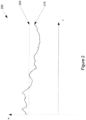
- Figure 2 is a graph 200 of a typical output signal of an accelerometer in the time domain.
- the output signal 210 can be thought of as comprising three components: the true value of the local gravity vector's projection along the axis of measurement as well as a "white noise” component, that is essentially independent of frequency, and a "red noise” component (sometimes also known as “coloured noise”) that is frequency dependent.
- the true value is shown by the dashed line 220 and is constant over the measurement interval.
- the red noise component is due mainly to the drifting bias of single-axis accelerometer 110 and is seen as the long wavelength change over time.
- the white noise component is seen as random, short wavelength variations.
- FIG. 3 shows a typical power spectral density (PSD) graph 300 of the output of an accelerometer in the frequency domain.
- the graph contains a red noise region and a white noise region with a transition that occurs at a cut-of frequency, ⁇ c .
- the drifting bias in single-axis accelerometer 110 is the dominant form of noise, resulting in an increase in the error as frequency decreases.
- the white noise region smaller random variations that do not contribute to drifting bias are the dominant form of noise.
- Instruments are designed to operate within the white noise region where the noise in the signal is most easily quantifiable and t c represents an approximate cap on the length of a single useful measurement.
- the RMS error in the measured acceleration could be made as small as one desires --- i.e., the acceleration measurement could be made as accurate as one desires --- by increasing the length of time over which the measurement is taken, and decreasing the bandwidth of a low-pass filter used to process the measurement. Alternately, the same could be accomplished by taking an increasingly large number of brief measurements, each of which has a larger RMS error than desired, then averaging these measurements together, with the RMS error of the averaged measurement decreasing with the square-root of the number of measurements.
- red noise interferes with this objective, having the effect of causing errors which can be relatively large when long, low-frequency measurements are made, or when a large number of brief measurements are made over a long period of time, typically a period of time longer than t c .
- red noise in the accelerometer measurement makes it difficult to reduce the accuracy of an accelerometer's measurement below some level.
- an absolute vector gravimeter in its simplest mode carries out at least two measurement cycles, preferably many more than two, as discussed in more detail below. Carrying out multiple measurement cycles allows each individual measurement to be of a short duration to limit the effect of bias drift, but compensates for the increased errors due to white noise on any single measurement by carrying out multiple measurement cycles. Synchronous demodulation of multiple measurement pairs collected over multiple measurement cycles in this way yields an estimate of the local gravity vector along the measurement axis where the error in the estimate is dominated by white noise, rather than by drifting bias. As such, the error in this measurement can be made arbitrarily small by increasing the number of measurement cycles and filtering the output signal to a lower bandwidth.
- T 2nt is the total measurement time and the lowest bandwidth to which the output can be filtered is approximately 1/T.
- the cut-off frequency also constrains the design of gimbal 112, and more specifically the slew rate of gimbal 112.
- the absolute vector gravimeter must be able to complete one measurement cycle before the bias wanders far enough to introduce a significant amount of error in the measurements.
- the amount of time per cycle spent slewing is less than half of t c .
- an exemplary method of measuring the projection of the local gravity vector along a measurement axis comprises:
- Additional components of the local gravity vector can be measured by taking static measurements at additional points along the range of single axis gimbal 112.
- single axis accelerometer 110 can be oriented along the positive and negative x-axes and the same calculation can be carried out.
- the absolute vector gravimeter of Figure 1A can also be used to estimate the local gravity vector along the x-axis by measuring once along the positive x-axis and using the bias estimate from the most recent opposed measurements along the z-axis to correct the value.
- a measurement includes the accelerometer bias plus the component of the gravity vector in the +x axis direction, plus an error due to noise; subtracting the previously-determined value of the bias from this produces a value equal to the component of the gravity vector in the +x axis direction (plus effects due to noise).
- one measurement cycle comprises:
- single axis accelerometers are each mounted on a single axis gimbal, optionally with the two gimbals oriented so that their gimbal axes are orthogonal to each other.
- the second gimbal is rotatable to point the second accelerometer in two opposite directions along a third measurement axis and a fourth measurement and a fifth measurement are taken in each of the two opposite directions along the third measurement axis.
- a third acceleration component and a second bias is determined from the fourth and the fifth measurement, thus allowing the calculation of all three spatial components of the local gravity vector by applying the preceding method to each of the x, y and z axes.
- a first unit may take measurements along the x and z axes while a second unit takes measurements along the y and z axes.
- the second unit may be operated such that it provides a redundant estimate of the gravity vector along one of the same measurement axes provided by the first unit (i.e. in the preceding example the z axis is measured by both units). Such redundancy may be used to check calibrations between units or combined to get a more accurate measurement along one axis.
- this embodiment can determine the magnitude of the local gravity vector without the instrument having first to be levelled with respect to the direction of the local gravity vector. Instead, this embodiment intrinsically measures the complete gravity vector, from which the vector's magnitude can be derived, rather than only measuring the gravity field's magnitude when erected to be vertical, as most present instruments generally do.
- a single-axis accelerometer can be mounted on a two-axis gimbal and sequentially moved through orientations along all three axes to calculate all three spatial components of the local gravity vector.
- these measurements can be made in directions aligned with an instrument-fixed reference frame, which need not be aligned to have one of its axes parallel to the local gravity vector.
- single axis gimbal 112 may be configured to orient single axis accelerometer 110 in directions other than directly along orthogonal axes. For example, it is possible to derive a de-biased estimate of the local gravity vector along the z-axis and the x-axis by taking measurements at zero degrees, 120 degrees and 240 degrees from the positive z-axis in the xz-plane. These 3 measurements are referred to below as m1, m2 and m3, respectively. Each measurement comprises the bias plus the cosine of the measurement angle multiplied by the +z component of gravity plus the sine of the measurement angle multiplied by the +x component of gravity.
- the accelerometer bias can be estimated using the formula ( m 1 + m 2 + m 3)/2
- the +x component of the gravity vector can be estimated using the formula m 2 ⁇ m 3 / 3
- the +z component of the gravity vector can be estimated using the formula ( m 1- m 2 - m 3)/2.
- Two such single-axis gimbal units oriented so that their rotation axes are orthogonal may therefore be able to provide de-biased estimates of all three spatial components of the local gravity vector.
- an absolute vector gravimeter 100 can also be used to measure non-ballistic accelerations other than those due only to gravity.
- An absolute vector gravimeter 100 as described is suitable for measuring components of the local gravity vector to a high degree of accuracy because, for a stationary object, the local gravity vector is effectively unchanging over the course of the measurement. The ability of the instrument to properly measure other accelerations is subject to the same constraint. More specifically, an absolute vector gravimeter 100 is able to measure an acceleration to a high degree of accuracy as long as that acceleration does not change appreciably during the total length of time spent collecting measurements, T. Relatively long duration nearly-constant accelerations experienced by spacecraft using low-thrust methods of propulsion, such as ion thrusters or solar sails, are examples where an absolute vector gravimeter 100 may be suitable
- the data acquisition electronics i.e. the processor
- the data acquisition electronics are located on the base and connected to the accelerometer(s) via a hard-wired connection, such as a cable wrap drum.
- a hard-wired connection such as a cable wrap drum.
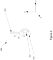
- Figure 4 shows a schematic representation of another embodiment of an absolute vector gravimeter 400 with a single axis accelerometer mounted on a single axis gimbal incorporating an angle sensor 414.
- This embodiment is similar to that shown in figure 1A including a single axis accelerometer 410 mounted on a single axis gimbal 412.
- an angle sensor 414 is used to measure the angular position of single axis accelerometer 412 when stationary and while slewing.
- Angle sensor 414 can also be configured to measure the angular speed, or slew rate, of single axis accelerometer 410 directly.
- multiple angle sensors may be provided, such as one sensor that measures angle and another sensor that measures angular rate.
- single axis accelerometer 410 takes measurements not only while stationary, but also while slewing, preferably but not necessarily at a constant angular speed, the total range of angular motion during such a slew being limited by the constraints imposed by the hard-wired connection between the accelerometer and the processor.
- Such measurements will include a centripetal acceleration component. If the physical characteristics of the instrument are well known, for example, they can be measured accurately before deployment, then the measured angular position and/or rate information can be combined with the known geometry to calculate an expected centripetal acceleration. Comparing the measured signal containing the centripetal acceleration component with the expected centripetal acceleration signal yields information about the end-to-end gain in the measurement system. This information can be used to correct acceleration values derived from the static measurements.
- a mathematical model of accelerometer 410 can be developed before deployment of absolute vector gravimeter 400 such that its physical characteristics are well known.
- the change in R with temperature can also be measured.
- Absolute vector gravimeter 400 will generally have a small, but repeatable error that depends on gimbal 412 angle. This could be due to many factors, including bearing imperfections and inaccuracy in angle sensor 414. This may be included in the instrument model (described in detail below) in order to improve the overall gain calibration.
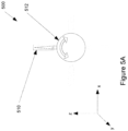
- Figure 5A shows a schematic representation of another embodiment of an absolute vector gravimeter 500 incorporating a single axis accelerometer 510 and 360 degree single axis gimbal 512.
- finding corrected acceleration measurements is accomplished by model fitting.
- gimbal 512 may move accelerometer 510 to point towards different static directions around a circle in the x-z plane, where a series of measurements is taken resulting in a series of measured values for acceleration.
- the real gravity signal will vary sinusoidally with the angle of accelerometer 510 as shown in the solid line of figure 5B .
- a model of the instrument can be developed that predicts an expected gravity signal curve given certain parameters and the measurement data can be fitted to it.
- Useful parameters have been found to include the tilt angle of gimbal 512 with respect to the local gravity field, and misalignment of the sensitive axis of accelerometer 510 with respect to the axis of gimbal 512.
- the number of measurements here functions much as the number of measurements does as described above: a greater number of measurements reduces the contribution of white noise in the same manner, RMS Noise ⁇ 1 n
- One single axis gimbal 512 with one single axis accelerometer 510 can be used to measure the components of the local gravity vector in two directions, e.g. x and z, as well as the bias in the single axis accelerometer 512.
- placing a second absolute vector gravimeter 500 oriented orthogonally to the first correspondingly allows measurement of the complete local gravity vector as well as correcting for the bias in both single axis accelerometers 512.
Landscapes
- Physics & Mathematics (AREA)
- Life Sciences & Earth Sciences (AREA)
- General Life Sciences & Earth Sciences (AREA)
- General Physics & Mathematics (AREA)
- Geophysics (AREA)
- Engineering & Computer Science (AREA)
- Manufacturing & Machinery (AREA)
- Gyroscopes (AREA)
- Measurement Of Mechanical Vibrations Or Ultrasonic Waves (AREA)
- Navigation (AREA)
- Testing Of Balance (AREA)
Claims (13)
- Absolutvektor-Gravimeter umfassend:Eine Basis;einen ersten Einzelachsen-Gimbal (112a, 112b), der betriebsbereit mit der Basis verbunden ist, der erste Einzelachsen-Gimbal ist konfiguriert, durch einen Winkel von mindestens 180° zu schwenken;einen ersten Einzelachsen-Beschleunigungsmesser (110), der betriebsbereit mit dem ersten Einzelachsen-Gimbal verbunden ist; undein zweiter Einzelachsen-Gimbal, der mit der Basis verbunden ist, der zweite Einzelachsen-Gimbal ist konfiguriert, durch einen Winkel von mindestens 180° zu schwenken;einen zweiten Einzelachsen-Beschleunigungsmesser (110), der betriebsbereit mit dem zweiten Einzelachsen-Gimbal verbunden ist; undeinen Prozessor, der betriebsbereit mit dem ersten Einzelachsen-Gimbal und dem ersten Einzelachsen-Beschleunigungsmesser, dem zweiten Einzelachsen-Gimbal und dem zweiten Einzelachsen-Beschleunigungsmesser verbunden ist,wobei, als Reaktion auf Signale von dem Prozessor,der erste Einzelachsen-Gimbal drehbar ist, um den ersten Einzelachsen-Beschleunigungsmesser in eine erste Richtung entlang der ersten Messachse zu stellen,der erste Einzelachsen-Gimbal ist ferner drehbar, um den ersten Einzelachsen-Beschleunigungsmesser in eine zweite Richtung zu stellen,wobei die zweite Richtung in einem Winkel von 180° zur ersten Richtung ausgerichtet ist, wobei die erste und die zweite Richtung in die entgegengesetzte Richtung entlang einer ersten Einzel-Messachse zeigen,der erste Einzelachsen-Gimbal ist ferner drehbar, um den ersten Einzelachsen-Beschleunigungsmesser in eine dritte Richtung entlang einer zweiten Messachse zu stellen, die zweite Messachse steht dabei senkrecht zu der ersten Messachse;wobei der erste Einzelachsen-Beschleunigungsmesser betriebsbereit ist, eine erste Messung einer ersten Komponente eines nicht-ballistischen Beschleunigungsvektors vorzunehmen, wenn er in die erste Richtung zeigt;der erste Einzelachsen-Beschleunigungsmesser betriebsbereit ist, eine zweite Messung einer zweiten Komponente des nicht-ballistischen Beschleunigungsvektors vorzunehmen, wenn er in die zweite Richtung zeigt;der erste Einzelachsen-Beschleunigungsmesser betriebsbereit ist, eine dritte Messung vorzunehmen,wenn er in die dritte Richtung zeigt,wobei, als Reaktion auf Drehsignale von dem Prozessor,der zweite Einzelachsen-Gimbal drehbar ist, um den zweiten Einzelachsen-Beschleunigungsmesser in eine vierte Richtung entlang der dritten Messachse zu stellen,und der zweite Einzelachsen-Gimbal drehbar ist, um den zweiten Einzelachsen-Beschleunigungsmesser in eine fünfte Richtung entlang der dritten Messachse zu stellen,wobei die fünfte Richtung in einem Winkel von 180° zur vierten Richtung ausgerichtet ist;wobei der zweite Einzelachsen-Beschleunigungsmesser betriebsbereit ist, eine vierte Messung vorzunehmen, wenn er in die vierte Richtung zeigt und eine fünfte Messung vorzunehmen, wenn er in die fünfte Richtung zeigt; undder Prozessor ist für Folgendes konfiguriert:i. Die Drehsignale zu erzeugen, um den ersten Einzelachsen-Gimbal und den zweiten Einzelachsen-Gimbal zu drehen;ii. die ersten Beschleunigungsmesser-Messsignale von dem ersten Einzelachsen-Beschleunigungsmesser zu empfangen;iii. die zweiten Beschleunigungsmesser-Messsignale von dem zweiten Einzelachsen-Beschleunigungsmesser zu empfangen; undiv. die erste Messung und die zweite Messung zu verwenden, um Komponenten zu bestimmen, durch Bestimmen einer ersten geschätzten Ausrichtung im ersten Einzelachsen-Beschleunigungsmesser unter Verwendung der ersten und zweiten Messung;Bestimmen einer ersten geschätzten nicht-ballistischen Beschleunigungskomponente unter Verwendung der ersten und zweiten Messung;Bestimmen einer zweiten geschätzten nicht-ballistischen Beschleunigungskomponente entlang der zweiten Messachse unter Verwendung der dritten Messung und der ersten geschätzten Ausrichtung; undBestimmen einer dritten geschätzten nicht-ballistischen Beschleunigungskomponente entlang der dritten Messachse und einer zweiten geschätzten Ausrichtung im zweiten Einzelachsen-Beschleunigungsmesser unter Verwendung der vierten Messung und der fünften Messung.
- Der Absolutvektor-Gravimeter nach Anspruch 1, wobei:i. der zweite Einzelachsen-Gimbal ferner drehbar ist, um den zweiten Einzelachsen-Beschleunigungsmesser in eine sechste Richtung entlang einer vierten Messachse zu stellen, wobei die vierte Messachse senkrecht zu der dritten Messachse steht;ii. der zweite Einzelachsen-Beschleunigungsmesser ferner betriebsbereit ist, eine sechste Messung vorzunehmen, wenn er in die sechste Richtung zeigt; undiii. der Prozessor konfiguriert ist, eine vierte geschätzte nicht-ballistische Beschleunigungskomponente entlang der vierten Messachse unter Verwendung der sechsten Messung und der zweiten geschätzten Ausrichtung zu bestimmen.
- Der Absolutvektor-Gravimeter nach Anspruch 2, wobei die erste Messachse und die dritte Messachse koaxial sind, wobei die erste geschätzte nicht-ballistische Beschleunigungskomponente und die dritte geschätzte nicht-ballistische Beschleunigungskomponente füreinander redundante Prüfungen liefern.
- Der Absolutvektor-Gravimeter nach Anspruch 2, wobei drei der Messachsen senkrecht zueinander sind, wobei der Prozessor konfiguriert ist, eine geschätzte nicht-ballistische Beschleunigungskomponente entlang jeder der drei senkrechten Achsen zu berechnen, wobei der Prozessor konfiguriert ist, die geschätzten nicht-ballistischen Beschleunigungskomponenten entlang jeder der drei senkrechten Achsen zu einem resultierenden Beschleunigungsvektor zusammenzufügen.
- Der Absolutvektor-Gravimeter nach Anspruch 1, wobei der Prozessor ferner konfiguriert ist, den ersten Einzelachsen-Gimbal, den zweiten Einzelachsen-Gimbal, den ersten Einzelachsen-Beschleunigungsmesser und den zweiten Einzelachsen-Beschleunigungsmesser zu regeln, um jede Messung viele Male zu wiederholen und die geschätzten nicht-ballistischen Beschleunigungskomponenten aus allen Messzyklen zusammenzufügen und dadurch den Effekt des Weißrauschens an den geschätzten nicht-ballistischen Beschleunigungskomponenten zu reduzieren.
- Der Absolutvektor-Gravimeter nach Anspruch 1, wobei der Prozessor mit dem ersten Einzelachsen-Beschleunigungsmesser über einen festverdrahteten Anschluss verbunden ist und dadurch den Winkelbereich begrenzt, durch den sich der erste Einzelachsen-Gimbal drehen kann.
- Der Absolutvektor-Gravimeter nach Anspruch 6, ferner umfassend einen Winkelsensor für die Messung von mindestens entweder; (i) der Winkelposition des ersten Einzelachsen-Beschleunigungsmessers und (ii) der Winkelgeschwindigkeit des ersten Einzelachsen-Beschleunigungsmessers, wenn der erste Einzelachsen-Gimbal schwenkt, wobei:der erste Einzelachsen-Beschleunigungsmesser betriebsbereit ist, eine Messung der zentripetalen Beschleunigungskomponente vorzunehmen, wenn der erste Einzelachsen-Gimbal schwenkt;der Prozessor ist ferner für Folgendes konfiguriert:Berechnen eines erwarteten Werts der Messung der zentripetalen Beschleunigungskomponente unter Verwendung bekannter geometrischer Eigenschaften des Absolutvektor-Gravimeters und einer Winkelsensor-Messung;Vergleichen der Messung der zentripetalen Beschleunigungskomponente mit dem erwarteten Wert der Messung der zentripetalen Beschleunigungskomponente, um eine Ende-zu-Ende-Kalibrierung für den Anstieg des Absolutvektor-Gravimeters zu erreichen; unddie erste gemessene Beschleunigung unter Verwendung der Ende-zu-Ende-Kalibrierung zu korrigieren.
- Der Absolutvektor-Gravimeter nach Anspruch 1, wobei die erste Messachse, die zweite Messachse und die dritte Messachse alle senkrecht zueinander sind, wobei der Prozessor konfiguriert ist, eine geschätzte nicht-ballistische Beschleunigungskomponente entlang jeder der drei senkrechten Achsen zu berechnen, wobei der Prozessor konfiguriert ist, die geschätzten nicht-ballistischen Beschleunigungskomponenten entlang jeder der drei senkrechten Achsen zu einem resultierenden Beschleunigungsvektor zusammenzufügen.
- Verfahren zur Messung von mindestens einer Komponente eines nicht-ballistischen Beschleunigungsvektors, umfassend:i. Positionieren eines ersten Einzelachsen-Beschleunigungsmessers, der in eine erste Richtung zeigt,ii. Verwenden des ersten Einzelachsen-Beschleunigungsmessers, um eine erste Messung in die erste Richtung vorzunehmen;iii. Drehen des ersten Einzelachsen-Beschleunigungsmessers, damit er in eine zweite Richtung zeigt, wobei die zweite Richtung in einem Winkel von 180° zu der ersten Richtung ausgerichtet ist, wobei die erste und die zweite Richtung in entgegengesetzte Richtungen entlang einer ersten Messachse zeigen;iv. Verwenden des ersten Einzelachsen-Beschleunigungsmessers, um eine zweite Messung in die zweite Richtung vorzunehmen; undv. Verwenden der ersten und der zweiten Messung, um eine geschätzte nicht-ballistische Beschleunigungskomponente entlang der Messachse zu berechnen;vi. Drehen des ersten Einzelachsen-Beschleunigungsmessers, damit er in eine dritte Richtung entlang einer zweiten Messachse zeigt, wobei die zweite Messachse senkrecht zu der ersten Messachse steht;vii. Verwenden des ersten Einzelachsen-Beschleunigungsmessers, um eine dritte Messung in die dritte Richtung vorzunehmen; entlang der zweiten Messachse; undviii. Verwenden der dritten Messung und der ersten geschätzten Ausrichtung, um eine zweite geschätzte nicht-ballistische Beschleunigungskomponente entlang der zweiten Messachse zu berechnen;ix. Ausrichten eines zweiten Einzelachsen-Beschleunigungsmessers in eine vierte Richtung entlang einer dritten Messachse;x. Verwenden des zweiten Einzelachsen-Beschleunigungsmessers, um eine vierte Messung in die vierte Richtung vorzunehmen;xi. Drehen des zweiten Einzelachsen-Beschleunigungsmessers, damit er in eine fünfte Richtung entlang der dritten Messachse zeigt, wobei die fünfte Richtung in einem Winkel von 180° zur vierten Richtung ausgerichtet ist;xii. Verwenden des zweiten Einzelachsen-Beschleunigungsmessers, um eine fünfte Messung in die fünfte Richtung vorzunehmen; undxiii. Verwenden der vierten und fünften Messung, um eine zweite geschätzte Ausrichtung in dem zweiten Einzelachsen-Beschleunigungsmesser und eine dritte geschätzte nicht-ballistische Beschleunigungskomponente entlang der dritten Messachse zu berechnen.
- Verfahren nach Anspruch 9, ferner umfassend:i. Drehen des zweiten Einzelachsen-Beschleunigungsmessers, damit er in eine sechste Richtung entlang einer vierten Messachse zeigt, wobei die vierte Messachse senkrecht zu der dritten Messachse steht;ii. Verwenden des zweiten Einzelachsen-Beschleunigungsmessers, um eine sechste Messung in die sechste Richtung vorzunehmen; undiii. Verwenden der sechsten Messung und der zweiten geschätzten Ausrichtung, um eine vierte geschätzte nicht-ballistische Beschleunigungskomponente entlang der vierten Messachse zu berechnen.
- Verfahren nach Anspruch 10, wobei die erste Messachse, die zweite Messachse und die dritte Messachse alle senkrecht zueinander sind, das Verfahren ferner umfassend das Berechnen einer geschätzten nicht-ballistischen Beschleunigungskomponente entlang jeder der drei senkrechten Achsen und Zusammenfügen der drei geschätzten nicht-ballistischen Beschleunigungskomponenten zu einem resultierenden Beschleunigungsvektor.
- Verfahren nach Anspruch 11, ferner umfassend das Berechnen einer Magnitude des resultierenden geschätzten nicht-ballistischen Beschleunigungsvektors durch das Berechnen der Quadratwurzel der Summe der Quadrate der drei geschätzten nicht-ballistischen Beschleunigungskomponenten.
- Verfahren nach Anspruch 9, ferner umfassend das vielmalige Wiederholen jeder Messung und Zusammenführen der geschätzten nicht-ballistischen Beschleunigungskomponenten aus allen Messzyklen, um den Effekt des Weißrauschens auf die geschätzten nicht-ballistischen Beschleunigungskomponenten zu reduzieren.
Applications Claiming Priority (2)
| Application Number | Priority Date | Filing Date | Title |
|---|---|---|---|
| US201461971885P | 2014-03-28 | 2014-03-28 | |
| PCT/CA2015/000191 WO2015143546A1 (en) | 2014-03-28 | 2015-03-30 | Absolute vector gravimeter and methods of measuring an absolute gravity vector |
Publications (4)
| Publication Number | Publication Date |
|---|---|
| EP3123209A1 EP3123209A1 (de) | 2017-02-01 |
| EP3123209A4 EP3123209A4 (de) | 2017-10-25 |
| EP3123209B1 true EP3123209B1 (de) | 2023-09-06 |
| EP3123209C0 EP3123209C0 (de) | 2023-09-06 |
Family
ID=54190037
Family Applications (1)
| Application Number | Title | Priority Date | Filing Date |
|---|---|---|---|
| EP15768304.6A Active EP3123209B1 (de) | 2014-03-28 | 2015-03-30 | Absolutvektor-gravimeter und verfahren zur messung eines absoluten schwerkraftvektors |
Country Status (5)
| Country | Link |
|---|---|
| US (1) | US10310132B2 (de) |
| EP (1) | EP3123209B1 (de) |
| CA (2) | CA2943443C (de) |
| ES (1) | ES2959449T3 (de) |
| WO (1) | WO2015143546A1 (de) |
Families Citing this family (8)
| Publication number | Priority date | Publication date | Assignee | Title |
|---|---|---|---|---|
| CA2973741C (en) | 2015-01-28 | 2024-01-23 | Gedex Systems Inc. | Inertial sensing augmentation for navigation of spacecraft |
| US11293778B1 (en) * | 2015-11-16 | 2022-04-05 | Tiax Llc | Attitude sensor system with automatic accelerometer bias correction |
| US11424449B2 (en) | 2019-01-25 | 2022-08-23 | Camx Power Llc | Stable cathode materials |
| US11796562B2 (en) * | 2020-05-29 | 2023-10-24 | Aivs Inc. | Acoustic intensity sensor using a MEMS triaxial accelerometer and MEMS microphones |
| CN112698416B (zh) * | 2020-12-16 | 2022-05-03 | 湖南航天机电设备与特种材料研究所 | 一种适用于捷联惯导系统的重力加速度测量方法及系统 |
| US12466508B2 (en) | 2021-02-23 | 2025-11-11 | Fox Factory, Inc. | Orientationally flexible bump sensor |
| CN116184517B (zh) * | 2022-12-23 | 2024-07-09 | 华中光电技术研究所(中国船舶集团有限公司第七一七研究所) | 一种基于单轴伺服结构的重力仪及其调平和测量方法 |
| US12278363B1 (en) | 2024-04-29 | 2025-04-15 | Camx Power, Llc | Multiple morphology composite cathode materials providing high energy and long cycle life and cells employing the same |
Family Cites Families (13)
| Publication number | Priority date | Publication date | Assignee | Title |
|---|---|---|---|---|
| US4749157A (en) | 1986-08-18 | 1988-06-07 | Hughes Aircraft Company | Spacecraft accelerometer auto-alignment |
| US4935883A (en) | 1988-05-17 | 1990-06-19 | Sundstrand Data Control, Inc. | Apparatus and method for leveling a gravity measurement device |
| US5357802A (en) * | 1993-05-07 | 1994-10-25 | Textron, Incorporated | Rotating accelerometer gradiometer |
| US5970787A (en) * | 1997-10-29 | 1999-10-26 | Schlumberger Technology Corporation | Downhole gravity tool |
| BR9910400A (pt) * | 1998-05-12 | 2001-09-04 | Lockheed Corp | Sistema e processo para recuperação secundária de hidrocarboneto |
| US6898970B2 (en) | 2003-06-05 | 2005-05-31 | International Business Machines Corporation | Inertial navigation device for ion propulsion driven spacecraft |
| US6918186B2 (en) | 2003-08-01 | 2005-07-19 | The Charles Stark Draper Laboratory, Inc. | Compact navigation system and method |
| US7641151B2 (en) | 2006-03-02 | 2010-01-05 | Pekka Janhunen | Electric sail for producing spacecraft propulsion |
| US8347711B2 (en) * | 2008-09-15 | 2013-01-08 | Lockheed Martin Corporation | Atom-interferometric, stepped gravity gradient measuring system |
| US8528381B2 (en) * | 2008-11-13 | 2013-09-10 | Halliburton Energy Services, Inc. | Downhole instrument calibration during formation survey |
| US8131494B2 (en) * | 2008-12-04 | 2012-03-06 | Baker Hughes Incorporated | Rotatable orientation independent gravity sensor and methods for correcting systematic errors |
| AU2012218782B2 (en) | 2011-02-17 | 2015-12-10 | Gedex Systems Inc. | Gravity gradiometer and methods for measuring gravity gradients |
| KR101416430B1 (ko) * | 2014-02-19 | 2014-07-10 | 한국지질자원연구원 | 해상 중력 측정 자료의 처리방법 및 이를 위한 처리장치 |
-
2015
- 2015-03-30 US US14/672,808 patent/US10310132B2/en active Active
- 2015-03-30 WO PCT/CA2015/000191 patent/WO2015143546A1/en not_active Ceased
- 2015-03-30 CA CA2943443A patent/CA2943443C/en active Active
- 2015-03-30 CA CA3169968A patent/CA3169968A1/en active Pending
- 2015-03-30 ES ES15768304T patent/ES2959449T3/es active Active
- 2015-03-30 EP EP15768304.6A patent/EP3123209B1/de active Active
Also Published As
| Publication number | Publication date |
|---|---|
| WO2015143546A1 (en) | 2015-10-01 |
| EP3123209A1 (de) | 2017-02-01 |
| CA2943443C (en) | 2022-11-01 |
| US10310132B2 (en) | 2019-06-04 |
| EP3123209C0 (de) | 2023-09-06 |
| EP3123209A4 (de) | 2017-10-25 |
| CA3169968A1 (en) | 2015-10-01 |
| CA2943443A1 (en) | 2015-10-01 |
| US20150276975A1 (en) | 2015-10-01 |
| ES2959449T3 (es) | 2024-02-26 |
Similar Documents
| Publication | Publication Date | Title |
|---|---|---|
| US10310132B2 (en) | Absolute vector gravimeter and methods of measuring an absolute gravity vector | |
| EP3617656B1 (de) | Trägheitsnavigationssystem | |
| US8005635B2 (en) | Self-calibrated azimuth and attitude accuracy enhancing method and system (SAAAEMS) | |
| EP2557394B1 (de) | System zur Verarbeitung von Impulssignalen innerhalb eines Trägheitsnavigationssystems | |
| CN101413800B (zh) | 导航/稳瞄一体化系统的导航、稳瞄方法 | |
| RU2566427C1 (ru) | Способ определения температурных зависимостей масштабных коэффициентов, смещений нуля и матриц ориентации осей чувствительности лазерных гироскопов и маятниковых акселерометров в составе инерциального измерительного блока при стендовых испытаниях | |
| US11293778B1 (en) | Attitude sensor system with automatic accelerometer bias correction | |
| CN112964240B (zh) | 一种连续寻北装置、方法、电子设备及存储介质 | |
| CN103808331A (zh) | 一种mems三轴陀螺仪误差标定方法 | |
| CN104764463B (zh) | 一种惯性平台调平瞄准误差的自检测方法 | |
| US8782913B2 (en) | Method of determining heading by turning an inertial device | |
| KR20140034716A (ko) | 항공우주 플랫폼의 각도 방향을 측정하는 시스템 및 방법 | |
| US20140249750A1 (en) | Navigational and location determination system | |
| CN112857400A (zh) | 一种基于十表冗余捷联惯组的运载火箭初始对准方法 | |
| Kaniewski et al. | Integrated system for heading determination | |
| RU2339002C1 (ru) | Способ определения навигационных параметров управляемых подвижных объектов и устройство для его осуществления | |
| RU2348009C1 (ru) | Гравиметрический способ определения уклонения отвесной линии в океане на подвижном объекте | |
| Tomaszewski et al. | Analysis of the noise parameters and attitude alignment accuracy of INS conducted with the use of MEMS-based integrated navigation system | |
| Sabir et al. | Simplification of calibration of low-cost MARG sensors without high-precision laboratory equipment | |
| Zhang et al. | Implementation and complexity analysis of orientation estimation algorithms for human body motion tracking using low-cost sensors | |
| Sotak | Testing the coarse alignment algorithm using rotation platform | |
| RU2674535C1 (ru) | Способ полевой калибровки магнитного компаса | |
| RU2671291C1 (ru) | Способ определения углов ориентации ЛА на вертикальных траекториях полета | |
| RU2785971C2 (ru) | Способ счисления координат при неортогональной ориентации входных осей измерителей параметров углового движения | |
| JP2001349733A (ja) | 方位センサ |
Legal Events
| Date | Code | Title | Description |
|---|---|---|---|
| STAA | Information on the status of an ep patent application or granted ep patent |
Free format text: STATUS: THE INTERNATIONAL PUBLICATION HAS BEEN MADE |
|
| PUAI | Public reference made under article 153(3) epc to a published international application that has entered the european phase |
Free format text: ORIGINAL CODE: 0009012 |
|
| STAA | Information on the status of an ep patent application or granted ep patent |
Free format text: STATUS: REQUEST FOR EXAMINATION WAS MADE |
|
| 17P | Request for examination filed |
Effective date: 20160930 |
|
| AK | Designated contracting states |
Kind code of ref document: A1 Designated state(s): AL AT BE BG CH CY CZ DE DK EE ES FI FR GB GR HR HU IE IS IT LI LT LU LV MC MK MT NL NO PL PT RO RS SE SI SK SM TR |
|
| AX | Request for extension of the european patent |
Extension state: BA ME |
|
| DAV | Request for validation of the european patent (deleted) | ||
| DAX | Request for extension of the european patent (deleted) | ||
| A4 | Supplementary search report drawn up and despatched |
Effective date: 20170921 |
|
| RIC1 | Information provided on ipc code assigned before grant |
Ipc: G01V 13/00 20060101ALI20170915BHEP Ipc: G01V 7/02 20060101AFI20170915BHEP |
|
| STAA | Information on the status of an ep patent application or granted ep patent |
Free format text: STATUS: EXAMINATION IS IN PROGRESS |
|
| 17Q | First examination report despatched |
Effective date: 20180517 |
|
| RAP1 | Party data changed (applicant data changed or rights of an application transferred) |
Owner name: 2241781 ONTARIO INC. |
|
| GRAP | Despatch of communication of intention to grant a patent |
Free format text: ORIGINAL CODE: EPIDOSNIGR1 |
|
| STAA | Information on the status of an ep patent application or granted ep patent |
Free format text: STATUS: GRANT OF PATENT IS INTENDED |
|
| INTG | Intention to grant announced |
Effective date: 20221018 |
|
| GRAJ | Information related to disapproval of communication of intention to grant by the applicant or resumption of examination proceedings by the epo deleted |
Free format text: ORIGINAL CODE: EPIDOSDIGR1 |
|
| STAA | Information on the status of an ep patent application or granted ep patent |
Free format text: STATUS: EXAMINATION IS IN PROGRESS |
|
| GRAS | Grant fee paid |
Free format text: ORIGINAL CODE: EPIDOSNIGR3 |
|
| STAA | Information on the status of an ep patent application or granted ep patent |
Free format text: STATUS: GRANT OF PATENT IS INTENDED |
|
| GRAP | Despatch of communication of intention to grant a patent |
Free format text: ORIGINAL CODE: EPIDOSNIGR1 |
|
| INTC | Intention to grant announced (deleted) | ||
| INTG | Intention to grant announced |
Effective date: 20230322 |
|
| GRAA | (expected) grant |
Free format text: ORIGINAL CODE: 0009210 |
|
| STAA | Information on the status of an ep patent application or granted ep patent |
Free format text: STATUS: THE PATENT HAS BEEN GRANTED |
|
| AK | Designated contracting states |
Kind code of ref document: B1 Designated state(s): AL AT BE BG CH CY CZ DE DK EE ES FI FR GB GR HR HU IE IS IT LI LT LU LV MC MK MT NL NO PL PT RO RS SE SI SK SM TR |
|
| REG | Reference to a national code |
Ref country code: GB Ref legal event code: FG4D |
|
| REG | Reference to a national code |
Ref country code: CH Ref legal event code: EP |
|
| REG | Reference to a national code |
Ref country code: IE Ref legal event code: FG4D |
|
| REG | Reference to a national code |
Ref country code: DE Ref legal event code: R096 Ref document number: 602015085572 Country of ref document: DE |
|
| U01 | Request for unitary effect filed |
Effective date: 20231006 |
|
| U07 | Unitary effect registered |
Designated state(s): AT BE BG DE DK EE FI FR IT LT LU LV MT NL PT SE SI Effective date: 20231012 |
|
| PG25 | Lapsed in a contracting state [announced via postgrant information from national office to epo] |
Ref country code: GR Free format text: LAPSE BECAUSE OF FAILURE TO SUBMIT A TRANSLATION OF THE DESCRIPTION OR TO PAY THE FEE WITHIN THE PRESCRIBED TIME-LIMIT Effective date: 20231207 |
|
| PG25 | Lapsed in a contracting state [announced via postgrant information from national office to epo] |
Ref country code: RS Free format text: LAPSE BECAUSE OF FAILURE TO SUBMIT A TRANSLATION OF THE DESCRIPTION OR TO PAY THE FEE WITHIN THE PRESCRIBED TIME-LIMIT Effective date: 20230906 Ref country code: NO Free format text: LAPSE BECAUSE OF FAILURE TO SUBMIT A TRANSLATION OF THE DESCRIPTION OR TO PAY THE FEE WITHIN THE PRESCRIBED TIME-LIMIT Effective date: 20231206 Ref country code: HR Free format text: LAPSE BECAUSE OF FAILURE TO SUBMIT A TRANSLATION OF THE DESCRIPTION OR TO PAY THE FEE WITHIN THE PRESCRIBED TIME-LIMIT Effective date: 20230906 Ref country code: GR Free format text: LAPSE BECAUSE OF FAILURE TO SUBMIT A TRANSLATION OF THE DESCRIPTION OR TO PAY THE FEE WITHIN THE PRESCRIBED TIME-LIMIT Effective date: 20231207 |
|
| REG | Reference to a national code |
Ref country code: ES Ref legal event code: FG2A Ref document number: 2959449 Country of ref document: ES Kind code of ref document: T3 Effective date: 20240226 |
|
| PG25 | Lapsed in a contracting state [announced via postgrant information from national office to epo] |
Ref country code: IS Free format text: LAPSE BECAUSE OF FAILURE TO SUBMIT A TRANSLATION OF THE DESCRIPTION OR TO PAY THE FEE WITHIN THE PRESCRIBED TIME-LIMIT Effective date: 20240106 |
|
| PG25 | Lapsed in a contracting state [announced via postgrant information from national office to epo] |
Ref country code: SM Free format text: LAPSE BECAUSE OF FAILURE TO SUBMIT A TRANSLATION OF THE DESCRIPTION OR TO PAY THE FEE WITHIN THE PRESCRIBED TIME-LIMIT Effective date: 20230906 Ref country code: RO Free format text: LAPSE BECAUSE OF FAILURE TO SUBMIT A TRANSLATION OF THE DESCRIPTION OR TO PAY THE FEE WITHIN THE PRESCRIBED TIME-LIMIT Effective date: 20230906 Ref country code: IS Free format text: LAPSE BECAUSE OF FAILURE TO SUBMIT A TRANSLATION OF THE DESCRIPTION OR TO PAY THE FEE WITHIN THE PRESCRIBED TIME-LIMIT Effective date: 20240106 Ref country code: CZ Free format text: LAPSE BECAUSE OF FAILURE TO SUBMIT A TRANSLATION OF THE DESCRIPTION OR TO PAY THE FEE WITHIN THE PRESCRIBED TIME-LIMIT Effective date: 20230906 Ref country code: SK Free format text: LAPSE BECAUSE OF FAILURE TO SUBMIT A TRANSLATION OF THE DESCRIPTION OR TO PAY THE FEE WITHIN THE PRESCRIBED TIME-LIMIT Effective date: 20230906 |
|
| U20 | Renewal fee for the european patent with unitary effect paid |
Year of fee payment: 10 Effective date: 20240401 |
|
| PG25 | Lapsed in a contracting state [announced via postgrant information from national office to epo] |
Ref country code: PL Free format text: LAPSE BECAUSE OF FAILURE TO SUBMIT A TRANSLATION OF THE DESCRIPTION OR TO PAY THE FEE WITHIN THE PRESCRIBED TIME-LIMIT Effective date: 20230906 |
|
| REG | Reference to a national code |
Ref country code: DE Ref legal event code: R097 Ref document number: 602015085572 Country of ref document: DE |
|
| PLBE | No opposition filed within time limit |
Free format text: ORIGINAL CODE: 0009261 |
|
| STAA | Information on the status of an ep patent application or granted ep patent |
Free format text: STATUS: NO OPPOSITION FILED WITHIN TIME LIMIT |
|
| 26N | No opposition filed |
Effective date: 20240607 |
|
| REG | Reference to a national code |
Ref country code: CH Ref legal event code: PL |
|
| PG25 | Lapsed in a contracting state [announced via postgrant information from national office to epo] |
Ref country code: MC Free format text: LAPSE BECAUSE OF FAILURE TO SUBMIT A TRANSLATION OF THE DESCRIPTION OR TO PAY THE FEE WITHIN THE PRESCRIBED TIME-LIMIT Effective date: 20230906 |
|
| PG25 | Lapsed in a contracting state [announced via postgrant information from national office to epo] |
Ref country code: MC Free format text: LAPSE BECAUSE OF FAILURE TO SUBMIT A TRANSLATION OF THE DESCRIPTION OR TO PAY THE FEE WITHIN THE PRESCRIBED TIME-LIMIT Effective date: 20230906 |
|
| PG25 | Lapsed in a contracting state [announced via postgrant information from national office to epo] |
Ref country code: IE Free format text: LAPSE BECAUSE OF NON-PAYMENT OF DUE FEES Effective date: 20240330 |
|
| PG25 | Lapsed in a contracting state [announced via postgrant information from national office to epo] |
Ref country code: IE Free format text: LAPSE BECAUSE OF NON-PAYMENT OF DUE FEES Effective date: 20240330 Ref country code: CH Free format text: LAPSE BECAUSE OF NON-PAYMENT OF DUE FEES Effective date: 20240331 |
|
| U20 | Renewal fee for the european patent with unitary effect paid |
Year of fee payment: 11 Effective date: 20250327 |
|
| PG25 | Lapsed in a contracting state [announced via postgrant information from national office to epo] |
Ref country code: CY Free format text: LAPSE BECAUSE OF FAILURE TO SUBMIT A TRANSLATION OF THE DESCRIPTION OR TO PAY THE FEE WITHIN THE PRESCRIBED TIME-LIMIT; INVALID AB INITIO Effective date: 20150330 |
|
| PG25 | Lapsed in a contracting state [announced via postgrant information from national office to epo] |
Ref country code: HU Free format text: LAPSE BECAUSE OF FAILURE TO SUBMIT A TRANSLATION OF THE DESCRIPTION OR TO PAY THE FEE WITHIN THE PRESCRIBED TIME-LIMIT; INVALID AB INITIO Effective date: 20150330 |
|
| PG25 | Lapsed in a contracting state [announced via postgrant information from national office to epo] |
Ref country code: TR Free format text: LAPSE BECAUSE OF FAILURE TO SUBMIT A TRANSLATION OF THE DESCRIPTION OR TO PAY THE FEE WITHIN THE PRESCRIBED TIME-LIMIT Effective date: 20230906 |
|
| PGFP | Annual fee paid to national office [announced via postgrant information from national office to epo] |
Ref country code: GB Payment date: 20260330 Year of fee payment: 12 |
|
| U20 | Renewal fee for the european patent with unitary effect paid |
Year of fee payment: 12 Effective date: 20260330 |
|
| PGFP | Annual fee paid to national office [announced via postgrant information from national office to epo] |
Ref country code: ES Payment date: 20260427 Year of fee payment: 12 |