EP3123273B1 - Système et procédé de détection d'activités au sein d'un dispositif informatique sur la base d'une surveillance de sa consommation énergétique - Google Patents
Système et procédé de détection d'activités au sein d'un dispositif informatique sur la base d'une surveillance de sa consommation énergétique Download PDFInfo
- Publication number
- EP3123273B1 EP3123273B1 EP15767848.3A EP15767848A EP3123273B1 EP 3123273 B1 EP3123273 B1 EP 3123273B1 EP 15767848 A EP15767848 A EP 15767848A EP 3123273 B1 EP3123273 B1 EP 3123273B1
- Authority
- EP
- European Patent Office
- Prior art keywords
- supply
- computerized
- environment
- monitoring unit
- power consumption
- Prior art date
- Legal status (The legal status is an assumption and is not a legal conclusion. Google has not performed a legal analysis and makes no representation as to the accuracy of the status listed.)
- Active
Links
Images


Classifications
-
- G—PHYSICS
- G06—COMPUTING OR CALCULATING; COUNTING
- G06F—ELECTRIC DIGITAL DATA PROCESSING
- G06F21/00—Security arrangements for protecting computers, components thereof, programs or data against unauthorised activity
- G06F21/70—Protecting specific internal or peripheral components, in which the protection of a component leads to protection of the entire computer
- G06F21/81—Protecting specific internal or peripheral components, in which the protection of a component leads to protection of the entire computer by operating on the power supply, e.g. enabling or disabling power-on, sleep or resume operations
-
- G—PHYSICS
- G06—COMPUTING OR CALCULATING; COUNTING
- G06F—ELECTRIC DIGITAL DATA PROCESSING
- G06F1/00—Details not covered by groups G06F3/00 - G06F13/00 and G06F21/00
- G06F1/26—Power supply means, e.g. regulation thereof
- G06F1/28—Supervision thereof, e.g. detecting power-supply failure by out of limits supervision
-
- G—PHYSICS
- G06—COMPUTING OR CALCULATING; COUNTING
- G06F—ELECTRIC DIGITAL DATA PROCESSING
- G06F21/00—Security arrangements for protecting computers, components thereof, programs or data against unauthorised activity
- G06F21/50—Monitoring users, programs or devices to maintain the integrity of platforms, e.g. of processors, firmware or operating systems
- G06F21/55—Detecting local intrusion or implementing counter-measures
- G06F21/552—Detecting local intrusion or implementing counter-measures involving long-term monitoring or reporting
-
- G—PHYSICS
- G06—COMPUTING OR CALCULATING; COUNTING
- G06F—ELECTRIC DIGITAL DATA PROCESSING
- G06F21/00—Security arrangements for protecting computers, components thereof, programs or data against unauthorised activity
- G06F21/50—Monitoring users, programs or devices to maintain the integrity of platforms, e.g. of processors, firmware or operating systems
- G06F21/55—Detecting local intrusion or implementing counter-measures
- G06F21/56—Computer malware detection or handling, e.g. anti-virus arrangements
- G06F21/566—Dynamic detection, i.e. detection performed at run-time, e.g. emulation, suspicious activities
-
- Y—GENERAL TAGGING OF NEW TECHNOLOGICAL DEVELOPMENTS; GENERAL TAGGING OF CROSS-SECTIONAL TECHNOLOGIES SPANNING OVER SEVERAL SECTIONS OF THE IPC; TECHNICAL SUBJECTS COVERED BY FORMER USPC CROSS-REFERENCE ART COLLECTIONS [XRACs] AND DIGESTS
- Y04—INFORMATION OR COMMUNICATION TECHNOLOGIES HAVING AN IMPACT ON OTHER TECHNOLOGY AREAS
- Y04S—SYSTEMS INTEGRATING TECHNOLOGIES RELATED TO POWER NETWORK OPERATION, COMMUNICATION OR INFORMATION TECHNOLOGIES FOR IMPROVING THE ELECTRICAL POWER GENERATION, TRANSMISSION, DISTRIBUTION, MANAGEMENT OR USAGE, i.e. SMART GRIDS
- Y04S40/00—Systems for electrical power generation, transmission, distribution or end-user application management characterised by the use of communication or information technologies, or communication or information technology specific aspects supporting them
- Y04S40/20—Information technology specific aspects, e.g. CAD, simulation, modelling, system security
Definitions
- the field of the invention relates in general to methods and systems for securing computerized environments and devices. More specifically, the invention relates to a method and system for securing a computerized device by means of monitoring of its electrical power consumption.
- Modern smartphones host various gadgets and sensors, such as GPS, Wi-Fi, voice, camera, accelerometers, etc.
- the normal activation of such components normally requires manual input from the user, typically by touching the screen.
- an unauthorized intrusion which introduces a malicious code may activate one or more of said sensitive component without the user's consent.
- This serious vulnerability is exploited by remote hostile agents to gather sensitive information through the subverted mobile phone.
- security software has been developed and is widely used for protecting mobile devices. In this respect, it should be noted that the security model of most mobile phone operating systems discourages some typical monitoring solutions that are available for personal computers and stationary devices.
- this detection technique may be used in association with other protection techniques.
- said monitoring of the device's power consumption is performed by a program that runs within the same computerized environment that it intends to protect.
- environment relates herein to a range of hardware and software, that are in turn accessible either physically (for example, via a USB connector) or wirelessly (for example, via a WiFi network).
- an “environment” is a close computerized range to which access is allowed only to authorized persons or programs, however, a "closed” environment may be breached by unauthorized activities, either via said physical connection or wirelessly.
- a same or another code may, for example, manipulate the protecting code (for example, anti-virus, or any other protecting software) to perform one of the following: (i) to stop operation; (ii) to ignore the existence of the malicious code within the protected environment; or (iii) to manipulate the code such that no report will be issued to the user with respect to the detection of the malicious code. Following this manipulation, the malicious code in fact can operate freely within the protected environment.
- the protecting code for example, anti-virus, or any other protecting software
- US 2008/027611 discloses an information processing electronic device capable of detecting undesired software by monitoring electric power consumption patterns.
- a sensor detects an amount of electric power or current consumed by the electronic device, and a threshold detector compares the detected electric power or current to a threshold value, to indicate that undesired software is present when the threshold is exceeded.
- the threshold detector is connected to a microprocessor which handles computing functions of the electronic device.
- WO2012/087685 discloses signature independent system bahaviour-based malware detection.
- the invention relates to a system for protecting a computerized device from a malicious activity resulting from a malicious code, which comprises: (a) a first DC supply monitoring unit which is located within a separate computerized environment, namely an environment which is totally separated and isolated both physically and in terms of connectivity from the hardware and software of the computerized environment of the device; (b) a memory database for storing one or more signatures of known malicious events, each of said signatures describes the temporal effect of a malicious event, respectively, on the power consumption from the DC supply of the device; and (c) a microprocessor within said DC supply monitoring unit for continuously monitoring the power consumption from said DC supply of the device, comparing temporal characteristics of the power consumption with said malicious events signatures in said database, and alerting upon detection of a match, wherein said DC supply monitoring unit is at most physically connected to the DC supply of the device.
- said first DC supply monitoring unit is positioned on a separate printed circuit, and wherein said microprocessor bases its monitoring on sampling of the current consumption from said DC supply.
- said computerized device is a mobile device, and wherein said DC supply is the battery of the device.
- said computerized device is a stationary device, and wherein said DC supply is the power supply of the device.
- said malicious events are combined from the occurrence of one or more of individual incidents.
- said alerting is provided by visual, audible, or a combination thereof of alert means that are positioned within said separated and isolated first DC supply monitoring unit.
- said visual means is a light emitting diode, and said visual means is a buzzer.
- the form and manner of the alert may be selected from several levels of alerts.
- the monitoring of the power consumption from the DC supply is performed by means of sampling of current consumption.
- said first DC supply monitoring unit is positioned on a separate printed board, and wherein said separate printed board having a port for communicating input and output data to and from the first DC supply monitoring unit.
- said port is used to update said database of one or more signatures.
- said memory also stores a first events log.
- the system further comprises: (a) a second DC supply monitoring program which runs within said computerized environment of the device simultaneously with said monitoring microprocessor that runs within said separate environment, and which forms a second events log; and (b) an external entity which extracts said first events log from the separate computerized environment and said second events log from the computerized environment of the device, and which compares said two logs to possibly detect mismatch of detected events, that hints to a malicious manipulation of said second DC supply monitoring unit.
- a second DC supply monitoring program which runs within said computerized environment of the device simultaneously with said monitoring microprocessor that runs within said separate environment, and which forms a second events log
- an external entity which extracts said first events log from the separate computerized environment and said second events log from the computerized environment of the device, and which compares said two logs to possibly detect mismatch of detected events, that hints to a malicious manipulation of said second DC supply monitoring unit.
- Fig. 1 illustrates in a simplified block diagram form the manner by which the prior art security system 10, such as a hypothetical system based on Zefferer operates.
- the protecting system 10 based on Zefferer typically operates by means of a running application to protect a computerized environment of 11 of a mobile device.
- the running application operates from within the protected environment 11, i.e., by means of the microprocessor of the mobile device and from the same memory on which the operating system and all the other programs and applications run on the device. Therefore, and as noted above, this protecting system 10, having the form of a program, is susceptible to malicious manipulations.
- the system 10 comprises a software-based battery monitoring unit 12 which monitors the power consumption from battery 13 to detect battery consumption events.
- a battery consumption event may be considered as any change with respect to the power consumption from the battery 13.
- the battery monitoring unit Upon detection of any of such event, the battery monitoring unit records the event characteristics, and compares these characteristics against each of the malicious code signatures that are stored within the malicious code signatures database 14. Upon finding of any match between the recorded event and a signature within the database, the monitoring unit issues an alert.
- Fig. 2 shows in a simplified block diagram form a protecting system 100 for protecting a computerized device (either mobile device or a stationary device), according to an embodiment of the present invention.
- the environment 111 is the conventional computerized environment (hardware and software) of the device.
- the DC supply 113 may be either a battery of the mobile device or a DC power supply of a stationary device and it feeds, as is conventional, DC voltage to the hardware portion of the environment 111.
- the DC supply monitoring unit 112 and the malicious events signatures database 114 are similar in their nature to the battery monitoring unit 12 and malicious events signatures 14 of Fig. 1 , respectively, however they operate on a computerized environment 150 which is totally isolated from the computerized environment 111 of the device.
- the battery monitoring unit 112 and the malicious events signatures database 114 are operated by a separate microprocessor (not shown) which is positioned on an individual printed circuit which is totally separated and isolated both physically and in terms of connectivity from both the hardware and software of the computerized environment 111 of the device.
- the DC supply 113 is shown external of the computerized environments 111 and 150, as the battery only feeds in parallel these two environments with DC voltage. However, there is no way whatsoever for interaction between these two environments 111 and 150, as they are totally separated and isolated one from the other both in terms of hardware physical separation and in terms of software separation.
- the DC supply monitoring unit 112 which is totally separated and isolated from the computerized environment of the device also comprises alert means (not shown).
- the alert may be provided to the user, visually, audibly or both.
- the visual alert may be provided to the user, for example, by means of a light emitting diode, and the audible alert may be provided by means of a buzzer.
- all the means for providing said alerts are located on the printed circuit which is totally separated and isolated from the computerized environment of the device.
- several levels of alert may be provided, and these levels may be reflected either visually of audibly.
- Fig. 3 illustrates the interconnections between the DC supply unit 112 and the two separate environments 111 and 150.
- the power consumption of the computerized environment 111 of the device can be analyzed by measuring the voltage and current of the device DC supply 113.
- the voltage of the DC supply is almost constant, so only the current provides significant data.
- Standard sampling equipment based on ADC Analog to Digital Converter
- ADC Analog to Digital Converter
- the resistor R can be connected: to the positive electrode of the DC supply or to the negative (ground) electrode.
- the resistor R is connected to the positive electrode, a differential amplifier for ADC (Analog to Digital Converter) is required.
- ADC Analog to Digital Converter
- the resistor is connected to the negative electrode of the DC supply, a single end connection can do the work.
- the first connection is preferred due to its smaller amount of interferences.
- the sampling rate has to be at least two times larger than the maximum frequency of the sampled data (based on the Nyquist rate).
- a setup according to the present invention was arranged to check a mobile phone for various activities.
- the measurement setup was based on a National InstrumentsTM ADC USB card, with differential analog inputs, with voltage range of ⁇ 10 Volt, 1.25MHz sample rate, and 16 bit ADC resolution.
- the card was connected to a PC through a USB connection, and data acquisition was performed using a LabviewTM program.
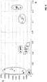
- the sampled data was represented in the frequency domain as shown in Fig. 4 .
- Most of the sampled signals were found to be pulses with a steep rise and a steep decline at the start and end of the pulse, respectively, and a nearly constant segment in between.
- the fast changes in the time domain were represented by high frequencies and the constant segment by low frequencies in the frequency domain.
- the frequency domain provides better separation between signals relating to different activities.
- the transformation from time to frequency domain was performed using FFT (Fast Fourier Transform) which separated the sampled signals to plurality of discrete frequencies in the frequency domain. Each discrete frequency is referred herein as "feature”.
- FFT Fast Fourier Transform
- Each discrete frequency is referred herein as "feature”.
- the number of the features by which the signals were examined varied depending on the sampling frequency and the time window selected. Different activities such as touch, Wi-Fi or GPS etc. were observed to have distinctive patterns over different sizes of time windows.
- the average window size for GPS and Wi-Fi was 4 seconds, and the window size for touch was between 100 to 300 mSec.
- Fig. 4 is a graph showing the f 4 vs. f 0 of several events, as detected in the experiment, together with their associated indices. The graph clearly shows that the events are distinguishable. As a result of this experiment, the distinguishing between these events in terms of power consumption enables forming of "events signatures", wherein each signature is a combination of the occurrence of one or more incidents (for example, the event no. 11 "GPS ON, Screen ON" comprises of two incidents). The results show a promising potential of the invention concept.
- the DC supply monitoring unit of the invention which is totally separated and isolated from the computerized environment of the device, also comprises alert means.
- an alert may be provided to the user, visually, audibly or both.
- the visual alert may be provided to the user, for example, by means of a light emitting diode, and the audible alert may be provided by means of a buzzer.
- all the means for providing said alerts are located on the printed circuit which is totally separated and isolated from the computerized environment of the device.
- the user may decide how to relate to the alert, and whether to take an action.
- the invention is applicable to detect various types of events, either malicious or not, and consequently the term "malicious”, wherever used herein, should be viewed to relate to both of said cases.
- the computerized environment 150 of the present invention (which typically comprises a separate microprocessor and memory) is totally isolated from the computerized environment 111 of the monitored device.
- the system of the invention is positioned on a separate printed board, which has no connection, either wire connection or wireless, with the computerized environment 111 of the device.
- the printed circuit of the invention preferably has an input output port, for example, a USB, RS232, etc. port for inputting and outputting data between elements on the printed circuit and the "external world". This port may be used, for example, to update the malicious events signatures database 114 with new signatures.
- the invention may be used in conjunction with a prior art application for detecting malicious events, i.e., an application which detects such events by monitoring power consumption from the battery of power supply, and which runs within the computerized environment 111 of the device.
- each of said environments creates its own log events, and saves it within its own environment (111 or 150), respectively. Once in a while, and offline (once in a week, once in a month, etc.), both of the saved logs may be downloaded and compared by means of a program which is external to both of said environments 111 and 150.
Landscapes
- Engineering & Computer Science (AREA)
- Theoretical Computer Science (AREA)
- Computer Security & Cryptography (AREA)
- Software Systems (AREA)
- Computer Hardware Design (AREA)
- General Engineering & Computer Science (AREA)
- Physics & Mathematics (AREA)
- General Physics & Mathematics (AREA)
- Health & Medical Sciences (AREA)
- General Health & Medical Sciences (AREA)
- Virology (AREA)
- Power Sources (AREA)
Claims (13)
- Système (100) pour protéger un dispositif informatisé contre une activité malveillante résultant d'un code malveillant, comprenant :a. un environnement informatisé (111) dudit dispositif informatisé ayant des ressources matérielles et logicielles qui est accessible à un réseau de données ;b. un environnement informatisé séparé (150) configuré avec des ressources matérielles et logicielles qui sont totalement séparées et isolées de l'environnement informatisé dudit dispositif informatisé en termes de séparation physique matérielle et en termes de séparation logicielle ;c. une alimentation en courant continu, CC (113), pour mettre sous tension l'environnement informatisé dudit dispositif informatisé ;d. une première unité de surveillance d'alimentation CC (112) à microprocesseur qui est située au sein dudit environnement informatisé séparé, dans lequel ladite première unité de surveillance d'alimentation CC est physiquement connectée à ladite alimentation CC et est configurée pour surveiller une consommation électrique issue de ladite alimentation CC ; ete. une base de données de mémoire (114) dans laquelle sont stockées une ou plusieurs signatures d'événements malveillants connus, chacune desdites signatures décrit l'effet temporel de l'un desdits événements malveillants connus sur la consommation électrique issue de l'alimentation CC du dispositif,dans lequel ladite première unité de surveillance d'alimentation CC comprend un moyen d'alerte conçu pour générer un signal d'alerte fourni à un utilisateur lors de la détection d'une concordance entre des caractéristiques temporelles surveillées de la consommation électrique issue de ladite alimentation CC et une ou plusieurs signatures parmi les signatures d'événements malveillants stockées dans ladite base de données.
- Système selon la revendication 1, dans lequel ledit microprocesseur est utilisable pour surveiller la consommation électrique par un échantillonnage de la consommation de courant issue de ladite alimentation CC (113).
- Système selon la revendication 1, dans lequel ledit dispositif informatisé est un dispositif mobile, et dans lequel ladite alimentation CC (113) est une batterie du dispositif.
- Système selon la revendication 1, dans lequel ledit dispositif informatisé est un dispositif stationnaire, et dans lequel ladite alimentation CC (113) est l'alimentation électrique du dispositif.
- Système selon la revendication 1, dans lequel chacune des signatures stockées est indicative d'une combinaison de l'effet temporel se rapportant à l'un desdits événements malveillants connus et d'un effet temporel se rapportant à un ou plusieurs incidents parmi des incidents individuels.
- Système selon la revendication 1, dans lequel ledit moyen d'alerte est sélectionné parmi un moyen d'alerte visuelle, un moyen d'alerte audible ou une combinaison de ceux-ci.
- Système selon la revendication 6, dans lequel ledit moyen d'alerte visuelle est une diode électroluminescente, et ledit moyen d'alerte audible est un bruiteur.
- Système selon la revendication 6, dans lequel la forme et la manière de l'alerte peuvent être sélectionnées parmi de nombreux niveaux d'alertes.
- Système selon la revendication 1, dans lequel ladite première unité de surveillance d'alimentation CC (112) est positionnée sur une carte de circuit imprimée séparée de, et non connectée à, l'environnement informatisé (111) du dispositif informatisé, et dans lequel ladite carte imprimée séparée possède un port pour communiquer des données d'entrée et de sortie vers et à partir de la première unité de surveillance d'alimentation CC (112).
- Système selon la revendication 9, dans lequel ledit port est utilisé pour mettre à jour ladite base de données de mémoire (114) d'une ou plusieurs signatures.
- Système selon la revendication 9, dans lequel ladite base de données de mémoire (114) stocke également un premier journal d'événements.
- Système selon la revendication 11, qui comprend en outre :a. une seconde unité de surveillance d'alimentation CC qui fonctionne au sein dudit environnement informatisé (111) du dispositif simultanément avec ladite première unité de surveillance d'alimentation CC (112) qui fonctionne au sein dudit environnement séparé (150), et est configurée pour générer un second journal d'événements qui est indicatif des caractéristiques temporelles surveillées de la consommation électrique dérivée de ladite alimentation CC ; etb. une entité externe qui extrait ledit premier journal d'événements à partir de l'environnement informatisé séparé et ledit second journal d'événements à partir de l'environnement informatisé du dispositif, et qui compare lesdits premier et second journaux d'événements pour détecter une discordance d'événements malveillants détectés qui reflète une manipulation malveillante de ladite seconde unité de surveillance d'alimentation CC.
- Système selon la revendication 1, dans lequel l'alimentation CC (113) est externe à, et alimente en parallèle avec une tension CC, l'environnement informatisé (111) dudit dispositif informatisé et ledit environnement informatisé séparé (150).
Applications Claiming Priority (2)
| Application Number | Priority Date | Filing Date | Title |
|---|---|---|---|
| US201461969179P | 2014-03-23 | 2014-03-23 | |
| PCT/IL2015/050297 WO2015145425A1 (fr) | 2014-03-23 | 2015-03-22 | Système et procédé de détection d'activités au sein d'un dispositif informatique sur la base d'une surveillance de sa consommation énergétique |
Publications (3)
| Publication Number | Publication Date |
|---|---|
| EP3123273A1 EP3123273A1 (fr) | 2017-02-01 |
| EP3123273A4 EP3123273A4 (fr) | 2017-10-18 |
| EP3123273B1 true EP3123273B1 (fr) | 2020-12-30 |
Family
ID=54194067
Family Applications (1)
| Application Number | Title | Priority Date | Filing Date |
|---|---|---|---|
| EP15767848.3A Active EP3123273B1 (fr) | 2014-03-23 | 2015-03-22 | Système et procédé de détection d'activités au sein d'un dispositif informatique sur la base d'une surveillance de sa consommation énergétique |
Country Status (4)
| Country | Link |
|---|---|
| US (1) | US10817605B2 (fr) |
| EP (1) | EP3123273B1 (fr) |
| IL (1) | IL247807B (fr) |
| WO (1) | WO2015145425A1 (fr) |
Families Citing this family (9)
| Publication number | Priority date | Publication date | Assignee | Title |
|---|---|---|---|---|
| EP3146407A4 (fr) | 2014-05-18 | 2018-01-03 | B.G. Negev Technologies & Applications Ltd., at Ben-Gurion University | Système et procédé de détection d'activités au sein d'une amorce d'un dispositif informatisé sur la base de la surveillance de la consommation d'énergie |
| US11436317B2 (en) * | 2017-02-21 | 2022-09-06 | Raptor Engineering LLC | Systems and methods for assuring integrity of operating system and software components at runtime |
| CN108874605B (zh) * | 2018-06-29 | 2021-09-17 | Oppo广东移动通信有限公司 | 显示屏测试方法、装置、电子设备及存储介质 |
| US11354411B2 (en) | 2020-03-18 | 2022-06-07 | Robert Bosch Gmbh | Microcontroller program instruction execution fingerprinting and intrusion detection |
| EP3933629A1 (fr) * | 2020-07-01 | 2022-01-05 | Nokia Technologies Oy | Appareil, procédé et programme informatique pour la détection de programmes malveillants |
| US12189767B2 (en) | 2020-09-25 | 2025-01-07 | Robert Bosch Gmbh | System and method for intrusion detection on a physical level using an internal analog to digital converter |
| US12175255B2 (en) * | 2020-10-09 | 2024-12-24 | Ruckus Ip Holdings Llc | Selective switching of an active partition in an electronic device |
| IL295876B2 (en) * | 2022-08-23 | 2023-10-01 | Salvador Tech Ltd | Backup Protection System and Method |
| WO2025210635A1 (fr) * | 2024-04-03 | 2025-10-09 | B.G. Negev Technologies And Applications Ltd. At Ben Gurion University. | Système et procédé de détection d'activités malveillantes dans un dispositif informatisé sur la base de sa consommation d'énergie ca |
Citations (1)
| Publication number | Priority date | Publication date | Assignee | Title |
|---|---|---|---|---|
| WO2012087685A1 (fr) * | 2010-12-23 | 2012-06-28 | Intel Corporation | Détection de maliciel indépendante des signatures et basée sur le comportement d'un système |
Family Cites Families (11)
| Publication number | Priority date | Publication date | Assignee | Title |
|---|---|---|---|---|
| US7184905B2 (en) * | 2003-09-29 | 2007-02-27 | Stefan Donald A | Method and system for monitoring power supplies |
| US7289875B2 (en) | 2003-11-14 | 2007-10-30 | Siemens Technology-To-Business Center Llc | Systems and methods for sway control |
| US7877621B2 (en) * | 2004-09-03 | 2011-01-25 | Virginia Tech Intellectual Properties, Inc. | Detecting software attacks by monitoring electric power consumption patterns |
| DE102006005053B4 (de) | 2006-02-03 | 2012-10-25 | Infineon Technologies Ag | Vorichtung und Verfahren zum Erfassen eines Angriffs auf eine elektrische Schaltung |
| GB2458158B (en) * | 2008-03-07 | 2010-06-23 | Alertme Com Ltd | Electrical appliance monitoring systems |
| US8332945B2 (en) * | 2009-06-05 | 2012-12-11 | The Regents Of The University Of Michigan | System and method for detecting energy consumption anomalies and mobile malware variants |
| US20120180126A1 (en) * | 2010-07-13 | 2012-07-12 | Lei Liu | Probable Computing Attack Detector |
| US20120158201A1 (en) * | 2010-12-20 | 2012-06-21 | Openpeak Inc. | System and method for providing security based on power consumption |
| CN103198256B (zh) * | 2012-01-10 | 2016-05-25 | 凹凸电子(武汉)有限公司 | 用于检测应用程序状态的检测系统及方法 |
| KR101864828B1 (ko) * | 2012-04-10 | 2018-06-05 | 삼성전자주식회사 | 전자 기기 관리 방법 및 장치 |
| US9147072B2 (en) * | 2013-10-28 | 2015-09-29 | Qualcomm Incorporated | Method and system for performing behavioral analysis operations in a mobile device based on application state |
-
2015
- 2015-03-22 EP EP15767848.3A patent/EP3123273B1/fr active Active
- 2015-03-22 US US15/128,352 patent/US10817605B2/en active Active
- 2015-03-22 WO PCT/IL2015/050297 patent/WO2015145425A1/fr not_active Ceased
-
2016
- 2016-09-14 IL IL247807A patent/IL247807B/en active IP Right Grant
Patent Citations (1)
| Publication number | Priority date | Publication date | Assignee | Title |
|---|---|---|---|---|
| WO2012087685A1 (fr) * | 2010-12-23 | 2012-06-28 | Intel Corporation | Détection de maliciel indépendante des signatures et basée sur le comportement d'un système |
Also Published As
| Publication number | Publication date |
|---|---|
| US20180173877A1 (en) | 2018-06-21 |
| US10817605B2 (en) | 2020-10-27 |
| EP3123273A4 (fr) | 2017-10-18 |
| WO2015145425A1 (fr) | 2015-10-01 |
| EP3123273A1 (fr) | 2017-02-01 |
| IL247807A0 (en) | 2016-11-30 |
| IL247807B (en) | 2021-04-29 |
Similar Documents
| Publication | Publication Date | Title |
|---|---|---|
| EP3123273B1 (fr) | Système et procédé de détection d'activités au sein d'un dispositif informatique sur la base d'une surveillance de sa consommation énergétique | |
| Clark et al. | {WattsUpDoc}: Power side channels to nonintrusively discover untargeted malware on embedded medical devices | |
| KR102160659B1 (ko) | 하드웨어-기반 마이크로-아키텍처 데이터를 이용한 이상 프로그램 실행의 검출 | |
| CN105247532B (zh) | 使用硬件特征的对异常进程的无监督的检测 | |
| EP2069993B1 (fr) | Système et procédé de sécurité pour la détection d'une intrusion dans un système informatisé | |
| US10296740B2 (en) | System and method for detecting activities within a bootstrap of a computerized device based on monitoring of power consumption | |
| US10462170B1 (en) | Systems and methods for log and snort synchronized threat detection | |
| Stolfo et al. | Anomaly detection in computer security and an application to file system accesses | |
| US20040250169A1 (en) | IDS log analysis support apparatus, IDS log analysis support method and IDS log analysis support program | |
| US10657257B2 (en) | Feature vector aggregation for malware detection | |
| Chiu et al. | Frequent pattern based user behavior anomaly detection for cloud system | |
| Bai et al. | Rascv2: Enabling remote access to side-channels for mission critical and iot systems | |
| Hu et al. | Research on Android ransomware protection technology | |
| Clark | The security and privacy implications of energy-proportional computing | |
| CN115694883A (zh) | 一种基于大数据的网络感知异常检测系统与方法 | |
| KR20140077405A (ko) | 사이버 공격 탐지 장치 및 방법 | |
| CN107358101B (zh) | 一种基于权限模式的勒索软件检测方法及系统 | |
| Barankova et al. | Software development and hardware means of hidden usb-keylogger devices identification | |
| WO2020040859A1 (fr) | Système et procédé de détection de cyber-attaque sur la base d'une reconnaissance non supervisée rapide de motifs de signal récurrents | |
| Ameen et al. | WaveSleuth: Retrospective PLC Memory for Anomaly Detection in Industrial Control Systems | |
| Dhakar et al. | A new model for intrusion detection based on reduced error pruning technique | |
| GB2503393A (en) | A patient monitoring system with image capture functionality | |
| Vyas et al. | Intrusion detection systems: a modern investigation | |
| Koli et al. | Detection of Malware for System Security | |
| CN106156647B (zh) | 信息泄露路径跟踪方法和设备 |
Legal Events
| Date | Code | Title | Description |
|---|---|---|---|
| STAA | Information on the status of an ep patent application or granted ep patent |
Free format text: STATUS: THE INTERNATIONAL PUBLICATION HAS BEEN MADE |
|
| PUAI | Public reference made under article 153(3) epc to a published international application that has entered the european phase |
Free format text: ORIGINAL CODE: 0009012 |
|
| STAA | Information on the status of an ep patent application or granted ep patent |
Free format text: STATUS: REQUEST FOR EXAMINATION WAS MADE |
|
| 17P | Request for examination filed |
Effective date: 20161021 |
|
| AK | Designated contracting states |
Kind code of ref document: A1 Designated state(s): AL AT BE BG CH CY CZ DE DK EE ES FI FR GB GR HR HU IE IS IT LI LT LU LV MC MK MT NL NO PL PT RO RS SE SI SK SM TR |
|
| AX | Request for extension of the european patent |
Extension state: BA ME |
|
| DAV | Request for validation of the european patent (deleted) | ||
| DAX | Request for extension of the european patent (deleted) | ||
| A4 | Supplementary search report drawn up and despatched |
Effective date: 20170919 |
|
| RIC1 | Information provided on ipc code assigned before grant |
Ipc: G06F 1/28 20060101AFI20170913BHEP Ipc: G06F 21/81 20130101ALI20170913BHEP Ipc: G06F 21/55 20130101ALI20170913BHEP |
|
| STAA | Information on the status of an ep patent application or granted ep patent |
Free format text: STATUS: EXAMINATION IS IN PROGRESS |
|
| 17Q | First examination report despatched |
Effective date: 20190916 |
|
| GRAP | Despatch of communication of intention to grant a patent |
Free format text: ORIGINAL CODE: EPIDOSNIGR1 |
|
| STAA | Information on the status of an ep patent application or granted ep patent |
Free format text: STATUS: GRANT OF PATENT IS INTENDED |
|
| INTG | Intention to grant announced |
Effective date: 20200723 |
|
| GRAS | Grant fee paid |
Free format text: ORIGINAL CODE: EPIDOSNIGR3 |
|
| GRAA | (expected) grant |
Free format text: ORIGINAL CODE: 0009210 |
|
| STAA | Information on the status of an ep patent application or granted ep patent |
Free format text: STATUS: THE PATENT HAS BEEN GRANTED |
|
| AK | Designated contracting states |
Kind code of ref document: B1 Designated state(s): AL AT BE BG CH CY CZ DE DK EE ES FI FR GB GR HR HU IE IS IT LI LT LU LV MC MK MT NL NO PL PT RO RS SE SI SK SM TR |
|
| REG | Reference to a national code |
Ref country code: GB Ref legal event code: FG4D |
|
| REG | Reference to a national code |
Ref country code: AT Ref legal event code: REF Ref document number: 1350579 Country of ref document: AT Kind code of ref document: T Effective date: 20210115 |
|
| REG | Reference to a national code |
Ref country code: DE Ref legal event code: R096 Ref document number: 602015064155 Country of ref document: DE |
|
| REG | Reference to a national code |
Ref country code: IE Ref legal event code: FG4D |
|
| PG25 | Lapsed in a contracting state [announced via postgrant information from national office to epo] |
Ref country code: FI Free format text: LAPSE BECAUSE OF FAILURE TO SUBMIT A TRANSLATION OF THE DESCRIPTION OR TO PAY THE FEE WITHIN THE PRESCRIBED TIME-LIMIT Effective date: 20201230 Ref country code: RS Free format text: LAPSE BECAUSE OF FAILURE TO SUBMIT A TRANSLATION OF THE DESCRIPTION OR TO PAY THE FEE WITHIN THE PRESCRIBED TIME-LIMIT Effective date: 20201230 Ref country code: NO Free format text: LAPSE BECAUSE OF FAILURE TO SUBMIT A TRANSLATION OF THE DESCRIPTION OR TO PAY THE FEE WITHIN THE PRESCRIBED TIME-LIMIT Effective date: 20210330 Ref country code: GR Free format text: LAPSE BECAUSE OF FAILURE TO SUBMIT A TRANSLATION OF THE DESCRIPTION OR TO PAY THE FEE WITHIN THE PRESCRIBED TIME-LIMIT Effective date: 20210331 |
|
| REG | Reference to a national code |
Ref country code: AT Ref legal event code: MK05 Ref document number: 1350579 Country of ref document: AT Kind code of ref document: T Effective date: 20201230 |
|
| PG25 | Lapsed in a contracting state [announced via postgrant information from national office to epo] |
Ref country code: BG Free format text: LAPSE BECAUSE OF FAILURE TO SUBMIT A TRANSLATION OF THE DESCRIPTION OR TO PAY THE FEE WITHIN THE PRESCRIBED TIME-LIMIT Effective date: 20210330 Ref country code: LV Free format text: LAPSE BECAUSE OF FAILURE TO SUBMIT A TRANSLATION OF THE DESCRIPTION OR TO PAY THE FEE WITHIN THE PRESCRIBED TIME-LIMIT Effective date: 20201230 Ref country code: SE Free format text: LAPSE BECAUSE OF FAILURE TO SUBMIT A TRANSLATION OF THE DESCRIPTION OR TO PAY THE FEE WITHIN THE PRESCRIBED TIME-LIMIT Effective date: 20201230 |
|
| REG | Reference to a national code |
Ref country code: NL Ref legal event code: MP Effective date: 20201230 |
|
| PG25 | Lapsed in a contracting state [announced via postgrant information from national office to epo] |
Ref country code: HR Free format text: LAPSE BECAUSE OF FAILURE TO SUBMIT A TRANSLATION OF THE DESCRIPTION OR TO PAY THE FEE WITHIN THE PRESCRIBED TIME-LIMIT Effective date: 20201230 |
|
| REG | Reference to a national code |
Ref country code: LT Ref legal event code: MG9D |
|
| PG25 | Lapsed in a contracting state [announced via postgrant information from national office to epo] |
Ref country code: RO Free format text: LAPSE BECAUSE OF FAILURE TO SUBMIT A TRANSLATION OF THE DESCRIPTION OR TO PAY THE FEE WITHIN THE PRESCRIBED TIME-LIMIT Effective date: 20201230 Ref country code: PT Free format text: LAPSE BECAUSE OF FAILURE TO SUBMIT A TRANSLATION OF THE DESCRIPTION OR TO PAY THE FEE WITHIN THE PRESCRIBED TIME-LIMIT Effective date: 20210430 Ref country code: SK Free format text: LAPSE BECAUSE OF FAILURE TO SUBMIT A TRANSLATION OF THE DESCRIPTION OR TO PAY THE FEE WITHIN THE PRESCRIBED TIME-LIMIT Effective date: 20201230 Ref country code: LT Free format text: LAPSE BECAUSE OF FAILURE TO SUBMIT A TRANSLATION OF THE DESCRIPTION OR TO PAY THE FEE WITHIN THE PRESCRIBED TIME-LIMIT Effective date: 20201230 Ref country code: CZ Free format text: LAPSE BECAUSE OF FAILURE TO SUBMIT A TRANSLATION OF THE DESCRIPTION OR TO PAY THE FEE WITHIN THE PRESCRIBED TIME-LIMIT Effective date: 20201230 Ref country code: EE Free format text: LAPSE BECAUSE OF FAILURE TO SUBMIT A TRANSLATION OF THE DESCRIPTION OR TO PAY THE FEE WITHIN THE PRESCRIBED TIME-LIMIT Effective date: 20201230 Ref country code: NL Free format text: LAPSE BECAUSE OF FAILURE TO SUBMIT A TRANSLATION OF THE DESCRIPTION OR TO PAY THE FEE WITHIN THE PRESCRIBED TIME-LIMIT Effective date: 20201230 |
|
| PG25 | Lapsed in a contracting state [announced via postgrant information from national office to epo] |
Ref country code: PL Free format text: LAPSE BECAUSE OF FAILURE TO SUBMIT A TRANSLATION OF THE DESCRIPTION OR TO PAY THE FEE WITHIN THE PRESCRIBED TIME-LIMIT Effective date: 20201230 Ref country code: AT Free format text: LAPSE BECAUSE OF FAILURE TO SUBMIT A TRANSLATION OF THE DESCRIPTION OR TO PAY THE FEE WITHIN THE PRESCRIBED TIME-LIMIT Effective date: 20201230 |
|
| PG25 | Lapsed in a contracting state [announced via postgrant information from national office to epo] |
Ref country code: IS Free format text: LAPSE BECAUSE OF FAILURE TO SUBMIT A TRANSLATION OF THE DESCRIPTION OR TO PAY THE FEE WITHIN THE PRESCRIBED TIME-LIMIT Effective date: 20210430 |
|
| REG | Reference to a national code |
Ref country code: DE Ref legal event code: R097 Ref document number: 602015064155 Country of ref document: DE |
|
| PG25 | Lapsed in a contracting state [announced via postgrant information from national office to epo] |
Ref country code: MC Free format text: LAPSE BECAUSE OF FAILURE TO SUBMIT A TRANSLATION OF THE DESCRIPTION OR TO PAY THE FEE WITHIN THE PRESCRIBED TIME-LIMIT Effective date: 20201230 Ref country code: IT Free format text: LAPSE BECAUSE OF FAILURE TO SUBMIT A TRANSLATION OF THE DESCRIPTION OR TO PAY THE FEE WITHIN THE PRESCRIBED TIME-LIMIT Effective date: 20201230 Ref country code: AL Free format text: LAPSE BECAUSE OF FAILURE TO SUBMIT A TRANSLATION OF THE DESCRIPTION OR TO PAY THE FEE WITHIN THE PRESCRIBED TIME-LIMIT Effective date: 20201230 |
|
| REG | Reference to a national code |
Ref country code: CH Ref legal event code: PL |
|
| PLBE | No opposition filed within time limit |
Free format text: ORIGINAL CODE: 0009261 |
|
| STAA | Information on the status of an ep patent application or granted ep patent |
Free format text: STATUS: NO OPPOSITION FILED WITHIN TIME LIMIT |
|
| PG25 | Lapsed in a contracting state [announced via postgrant information from national office to epo] |
Ref country code: DK Free format text: LAPSE BECAUSE OF FAILURE TO SUBMIT A TRANSLATION OF THE DESCRIPTION OR TO PAY THE FEE WITHIN THE PRESCRIBED TIME-LIMIT Effective date: 20201230 Ref country code: ES Free format text: LAPSE BECAUSE OF FAILURE TO SUBMIT A TRANSLATION OF THE DESCRIPTION OR TO PAY THE FEE WITHIN THE PRESCRIBED TIME-LIMIT Effective date: 20201230 |
|
| 26N | No opposition filed |
Effective date: 20211001 |
|
| REG | Reference to a national code |
Ref country code: BE Ref legal event code: MM Effective date: 20210331 |
|
| PG25 | Lapsed in a contracting state [announced via postgrant information from national office to epo] |
Ref country code: IE Free format text: LAPSE BECAUSE OF NON-PAYMENT OF DUE FEES Effective date: 20210322 Ref country code: CH Free format text: LAPSE BECAUSE OF NON-PAYMENT OF DUE FEES Effective date: 20210331 Ref country code: LI Free format text: LAPSE BECAUSE OF NON-PAYMENT OF DUE FEES Effective date: 20210331 Ref country code: LU Free format text: LAPSE BECAUSE OF NON-PAYMENT OF DUE FEES Effective date: 20210322 |
|
| PG25 | Lapsed in a contracting state [announced via postgrant information from national office to epo] |
Ref country code: SI Free format text: LAPSE BECAUSE OF FAILURE TO SUBMIT A TRANSLATION OF THE DESCRIPTION OR TO PAY THE FEE WITHIN THE PRESCRIBED TIME-LIMIT Effective date: 20201230 |
|
| PG25 | Lapsed in a contracting state [announced via postgrant information from national office to epo] |
Ref country code: IS Free format text: LAPSE BECAUSE OF FAILURE TO SUBMIT A TRANSLATION OF THE DESCRIPTION OR TO PAY THE FEE WITHIN THE PRESCRIBED TIME-LIMIT Effective date: 20210430 |
|
| PG25 | Lapsed in a contracting state [announced via postgrant information from national office to epo] |
Ref country code: BE Free format text: LAPSE BECAUSE OF NON-PAYMENT OF DUE FEES Effective date: 20210331 |
|
| REG | Reference to a national code |
Ref country code: DE Ref legal event code: R082 Ref document number: 602015064155 Country of ref document: DE Representative=s name: CBDL PATENTANWAELTE GBR, DE Ref country code: DE Ref legal event code: R082 Ref document number: 602015064155 Country of ref document: DE Representative=s name: CBDL PATENTANWAELTE EGBR, DE |
|
| PG25 | Lapsed in a contracting state [announced via postgrant information from national office to epo] |
Ref country code: HU Free format text: LAPSE BECAUSE OF FAILURE TO SUBMIT A TRANSLATION OF THE DESCRIPTION OR TO PAY THE FEE WITHIN THE PRESCRIBED TIME-LIMIT; INVALID AB INITIO Effective date: 20150322 |
|
| P01 | Opt-out of the competence of the unified patent court (upc) registered |
Effective date: 20230512 |
|
| PG25 | Lapsed in a contracting state [announced via postgrant information from national office to epo] |
Ref country code: CY Free format text: LAPSE BECAUSE OF FAILURE TO SUBMIT A TRANSLATION OF THE DESCRIPTION OR TO PAY THE FEE WITHIN THE PRESCRIBED TIME-LIMIT Effective date: 20201230 |
|
| PG25 | Lapsed in a contracting state [announced via postgrant information from national office to epo] |
Ref country code: SM Free format text: LAPSE BECAUSE OF FAILURE TO SUBMIT A TRANSLATION OF THE DESCRIPTION OR TO PAY THE FEE WITHIN THE PRESCRIBED TIME-LIMIT Effective date: 20201230 |
|
| PG25 | Lapsed in a contracting state [announced via postgrant information from national office to epo] |
Ref country code: MK Free format text: LAPSE BECAUSE OF FAILURE TO SUBMIT A TRANSLATION OF THE DESCRIPTION OR TO PAY THE FEE WITHIN THE PRESCRIBED TIME-LIMIT Effective date: 20201230 |
|
| PG25 | Lapsed in a contracting state [announced via postgrant information from national office to epo] |
Ref country code: MT Free format text: LAPSE BECAUSE OF FAILURE TO SUBMIT A TRANSLATION OF THE DESCRIPTION OR TO PAY THE FEE WITHIN THE PRESCRIBED TIME-LIMIT Effective date: 20201230 |
|
| PG25 | Lapsed in a contracting state [announced via postgrant information from national office to epo] |
Ref country code: TR Free format text: LAPSE BECAUSE OF FAILURE TO SUBMIT A TRANSLATION OF THE DESCRIPTION OR TO PAY THE FEE WITHIN THE PRESCRIBED TIME-LIMIT Effective date: 20201230 |
|
| PGFP | Annual fee paid to national office [announced via postgrant information from national office to epo] |
Ref country code: FR Payment date: 20251231 Year of fee payment: 12 |
|
| PGFP | Annual fee paid to national office [announced via postgrant information from national office to epo] |
Ref country code: GB Payment date: 20260106 Year of fee payment: 12 |
|
| PGFP | Annual fee paid to national office [announced via postgrant information from national office to epo] |
Ref country code: DE Payment date: 20260102 Year of fee payment: 12 |