EP3123480B1 - Transferbehälter zur verwendung beim transferieren von stoffen zwischen radioaktiven abschirmbehältern - Google Patents
Transferbehälter zur verwendung beim transferieren von stoffen zwischen radioaktiven abschirmbehältern Download PDFInfo
- Publication number
- EP3123480B1 EP3123480B1 EP14718173.9A EP14718173A EP3123480B1 EP 3123480 B1 EP3123480 B1 EP 3123480B1 EP 14718173 A EP14718173 A EP 14718173A EP 3123480 B1 EP3123480 B1 EP 3123480B1
- Authority
- EP
- European Patent Office
- Prior art keywords
- lid
- transfer
- hot cell
- transfer vessel
- product
- Prior art date
- Legal status (The legal status is an assumption and is not a legal conclusion. Google has not performed a legal analysis and makes no representation as to the accuracy of the status listed.)
- Active
Links
Images

Classifications
-
- G—PHYSICS
- G21—NUCLEAR PHYSICS; NUCLEAR ENGINEERING
- G21F—PROTECTION AGAINST X-RADIATION, GAMMA RADIATION, CORPUSCULAR RADIATION OR PARTICLE BOMBARDMENT; TREATING RADIOACTIVELY CONTAMINATED MATERIAL; DECONTAMINATION ARRANGEMENTS THEREFOR
- G21F5/00—Transportable or portable shielded containers
- G21F5/06—Details of, or accessories to, the containers
- G21F5/12—Closures for containers; Sealing arrangements
-
- G—PHYSICS
- G21—NUCLEAR PHYSICS; NUCLEAR ENGINEERING
- G21F—PROTECTION AGAINST X-RADIATION, GAMMA RADIATION, CORPUSCULAR RADIATION OR PARTICLE BOMBARDMENT; TREATING RADIOACTIVELY CONTAMINATED MATERIAL; DECONTAMINATION ARRANGEMENTS THEREFOR
- G21F5/00—Transportable or portable shielded containers
- G21F5/06—Details of, or accessories to, the containers
- G21F5/14—Devices for handling containers or shipping-casks, e.g. transporting devices loading and unloading, filling of containers
-
- G—PHYSICS
- G21—NUCLEAR PHYSICS; NUCLEAR ENGINEERING
- G21F—PROTECTION AGAINST X-RADIATION, GAMMA RADIATION, CORPUSCULAR RADIATION OR PARTICLE BOMBARDMENT; TREATING RADIOACTIVELY CONTAMINATED MATERIAL; DECONTAMINATION ARRANGEMENTS THEREFOR
- G21F7/00—Shielded cells or rooms
- G21F7/005—Shielded passages through walls; Locks; Transferring devices between rooms
Definitions
- THIS invention relates to a transfer vessel for use in transferring products between radiation containment chambers, and more particularly but not exclusively, to transfer products from one chamber to another without cross-contamination.
- the invention also relates to a process of transferring products between radiation containment chambers without cross-contamination.
- Hot cells Shielded nuclear radiation containment chambers are commonly referred to as hot cells, with the word "hot” in this context referring to radioactivity.
- Hot cells are used in both the nuclear-energy and the nuclear-medicines industries. They are required to protect individuals from radioactive isotopes by providing a safe containment chamber inside which scientists and routine operators can work with the radioactive material using suitable control and manipulation equipment. Hot cells are, for example, commonly used in the nuclear medicines industry in the production of radiopharmaceuticals.
- the transfer vessel comprises a cylindrical receptacle having a first closed end and a second open end.
- a flange formation extends radially outwardly from the second open end, and in use engages a complementary receiving formation provided on the hot cell in order for the receptacle to be securable to the hot cell.
- a lid is also provided, and in use closes off the inner volume of the receptacle.
- the lid engages the container, and in particular includes a connecting formation which is complementary to a flange and receiving formation extending inwardly from the flange formation on the open end of the receptacle.
- the lid is of the same dimensions and configuration of a door provided in the hot cell.
- the lid and the door in the hot cell are furthermore adapted to engage one another in use so as to form a door-lid combination. Furthermore, when the door of the hot cell is opened, the lid contemporaneously disengages from the receptacle, in order for the lid to be opened when the door of the hot cell is opened. Importantly, during operation the operatively outer surface of the lid is covered and hence shielded by the operatively outer surface of the door of the hot cell, and neither surface is therefore exposed to radiation when the door-lid combination is opened.
- a number of standard door sizes are used in industry, and some hot cells have more than one door (for example a 270mm diameter door and a concentric 105mm diameter door) in order to receive differently sized transfer vessels having different lid sizes.
- the product cannot merely be transferred between the first and second hot cell using a transfer vessel, as the inside of the transfer vessel will in use be in sequential flow communication with the insides of both hot cells, thus resulting in contamination of the second hot cell by exposure to contaminants emanating from the first hot cell, with the transfer vessel effectively serving as contamination conduit.
- the transfer vessel therefore remains "clean" during this step as do the outside of the lid of the second container and the inside of the lid of the transfer vessel by virtue of their engagement as described above.
- the lid-combination of the transfer vessel and the second container is then closed (with the product now housed inside the second container) and the transfer vessel is ready for transportation.
- the transfer vessel subsequently engages the target hot cell, in such a way that this time only the lid of the transfer vessel is engaged to the door of the target hot cell so that the second container, still in a closed state, may be moved into the target hot cell.
- the inner volume of the transfer vessel will be contaminated by any contamination of the second hot cell, but this does not matter because the transfer has been effected, and no further contamination can occur.
- the lid can be closed, and the second container, housing the product, remains behind in the target hot cell. It is correct that the target hot cell has, at this time, not been contaminated from contaminants emanating from the contaminated first hot cell.
- the target cell will be contaminated if the second container is opened in order to provide access to the product. It follows that the above process will only be useful for the purposes of storage, and that it will not prevent contamination when there is a need to work with the product inside the target cell.
- a transfer vessel as set out in claim 1, suitable for use in transferring products between radiation containment chambers, the transfer vessel including:
- the lid and the displaceable closure are configured to engage two complementary doors provided on the hot cell contemporaneously.
- the lid and the displaceable closure are also configured to be displaceable between open and closed positions independently from one another so as to allow only the displaceable closure or the combination of the lid and the displaceable closure to be displaced when a corresponding door on the hot cell is displaced.
- a product transfer arrangement to be provided between the first enclosed volume and the second enclosed volume, the product transfer arrangement enabling the transfer of product between the enclosed volumes without allowing transfer of contaminating matter between the enclosed volumes.
- the product transfer arrangement may be in the form of a septum which enables the use of a cannula transfer process.
- the transfer arrangement includes two septa.
- a storage container or sample vessel for receiving the product may be provided inside the first enclosed volume, and may be in flow communication with the septum by way of a suitable conduit.
- outer receptacle and the inner receptacle are of cylindrical configuration.
- the inner receptacle may be integrally formed with the lid, or may be releasably securable inside a complementary aperture provided in the lid.
- the septum may be located in an end wall of the inner receptacle.
- a method of transferring products between radiation containment chambers including the steps of:
- first closure to be selectively closed off by a displaceable lid
- second closure to be selectively closed off by a displaceable closure in the lid
- lid and the displaceable closure contemporaneously to engage two complementary doors provided on the hot cell when the transfer vessel is secured to the hot cell.
- the transfer vessel is the transfer vessel as referred to above.
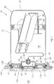
- a non-limiting example of a transfer vessel for use in transferring products between radiation containment chambers in accordance with the invention is generally indicated by reference numeral 10.
- Radiation containment chambers or hot cells are well known in the trade, and are not discussed in any detail. Suffice it to say that these hot cells (not shown) include an enclosed volume 120 which is sufficiently shielded from the environment to house radioactive material. The enclosed volume 120 can be accessed through a door 110. During use, a transfer vessel 10 is secured relative to the door 110 on the outside of the hot cell, in order for the inner volume 25 of the transfer vessel to be exposed to the enclosed volume 120 of the hot cell when the door 110 is opened.
- the door 110 of the hot cell and the lid 40 of the transfer vessel are designed to be of a complementary nature, and to effectively become a single unit once the transfer vessel is secured to the hot cell.
- the lid 40 of the transfer vessel remains engaged to the door 110 of the hot cell, and they therefore open and close as a single unit.
- the significance of this is that the operatively outer faces of both the door and the lid are not exposed to the enclosed volume of the hot cell during the transfer process, and are therefore also not contaminated.
- This feature is not new, but is an important aspect of hot cell technology that has also been incorporated into the present invention.
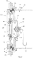
- the first hot cell 100 (not shown) includes a double door 110 that consists of a small circular inner door 111 and a large circular outer door 112.
- the inner door 111 is located on the outer door 112, but can be opened and closed independently of the outer door 112.
- a flange receiving formation 130 extends from a sidewall 140 of the hot cell.
- the transfer vessel 10 includes an outer receptacle 20, and an inner receptacle 30 and a lid 40.
- the outer receptacle 20 is in the form of a cylindrical body 21 having a closed end 22 and an open end 23.
- a securing flange 24 extends radially outwardly from the open end 23 of the cylindrical body 21, and is configured and dimensioned to engage the flange receiving formation 130 extending from the sidewall 140 of the hot cell.
- the arrangement may be a bayonet or screw type engagement configuration in which the transfer vessel 10 is secured to the hot cell upon rotation of the transfer vessel 10, and hence the securing flange 24, relative to the hot cell, and hence the flange receiving formation 130.
- a first enclosed volume 25 is defined inside the outer receptacle 20.
- the inner receptacle 30 is located inside the outer receptacle 20.
- the inner receptacle 30 is in the form of a cylindrical body 31 having a closed end 32 and an open end 33, with a second enclosed volume 35 defined inside the inner receptacle 30.
- the inner receptacle does not have to be of large volume, and will be sized depending on the purpose that it will fulfil, as is described in more detail below.
- the inner receptacle 30 is formed as part of the lid 40, or is alternatively securable to the lid 40, in order for the lid 40 and the inner receptacle 30 to be functionally integral in use.
- the lid 40 removably seals off the outer receptacle, and can be removed or opened (together with the inner receptacle 30) to provide access to the outer receptacle 20.
- the lid 40 includes a displaceable closure 43 suitable for covering the open end 33 of the inner receptacle 30 when in use.
- the displaceable closure 43 can be removed from the lid 40 when the small door 111 of the hot cell engages engagement formations 42 provided on the outer surface of the displaceable closure 43 while at the same time the engagement formation 34 engaging the displaceable closure 43 to the inner receptacle 30 is thereby disengaged, as is known in the art.
- the lid 40 in totality also acts as a removable cover for the open end 23 of the outer receptacle 20.
- engagement formations 41 are provided, and are in use engaged by the large door 112 while engagement formation 44 is simultaneously disengaged in order for the lid 40 to be displaced away from the outer receptacle 20 when the large door 112 of the hot cell is opened.
- the lid 40 is therefore configured to allow selective access to either the outer receptacle 20 or the inner receptacle 30, depending which one of the complementary sized and configured doors (112 or 111 respectively) of the hot cell is opened.
- a transfer arrangement 50 is provided for transferring product from the inner receptacle 30 to the outer receptacle 20.
- the transfer arrangement 50 is typically in the form of a dual septum arrangement 51 of which one end is in flow communication with the inner receptacle 30 through a connecting spigot 52, and an opposing end is in flow communication with the outer receptacle 20 through a connecting spigot 53.
- a sample vessel 60 is located on a rotating basket 65 inside the outer receptacle 20.
- the rotating basket 65 ensures that the sample vessel 60 remains upright through gravitational bias, even when the transfer vessel 10 is rotated.
- the sample vessel 60 is in flow communication with the transfer arrangement 50 by way of a conduit 61 that extends between the sample vessel 60 and the connecting spigot 53.
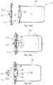
- FIG. 3(a) shows a transfer vessel 10 in accordance with the invention, the transfer vessel including an outer receptacle 20 and an inner receptacle 30 as described above. Both receptacles are at this time sealed from the environment by way of the closed lid 40 and closure 43.
- the door 110 of the first hot cell 100 (not shown) is also in a closed position, and more particularly both the small door 111 and the large door 112 are closed. At this time the inside 120 of the first hot cell is therefore isolated from the environment, as is the enclosed volumes of both the outer receptacle 20 and the inner receptacle 30. It is important to note that the two receptacles are also not in flow communication with one another, even though the inner receptacle 30 is at least partially housed inside the outer receptacle 20 and lid 40.
- the transfer vessel 10 is secured to the door 110 of the first hot cell by rotating the transfer vessel relative to the hot cell in order for the securing flange 24 that extends from the open end 23 of the outer receptacle 20 to engage the complementary flange receiving formation 130 provided on the first hot cell.
- the large door 112 engages the lid 40 of the transfer vessel 10 at engagement formation 41
- the small door 111 engages the displaceable closure 43 provided on the lid 40 at engagement formation 42.
- the lid 40 and the large door 112 temporarily becomes a single functional object, as do the closure 43 and the small door 111.
- Opening of the large door 112 will therefore automatically result in opening of the lid 40, whereas opening of the small door 111 will also result in opening of the closure 43.
- This is not only important from an operational point of view, but also insofar as contamination is concerned, because neither the outer surface of the doors (111 and 112) nor the outer surfaces of the lid 40 and closure 43 will be exposed to the inside of the first hot cell, and will therefore not be contaminated.
- the product 70 can now be transferred from the inner receptacle 30 to the outer receptacle 20 by way of the product transfer arrangement 50, which in this particular example is in the form of a septum arrangement 51 as described above. More particularly, the product 70 is transferred to the product cylinder or sample vessel 60 located inside the outer receptacle 20.
- the product transfer arrangement 50 which in this particular example is in the form of a septum arrangement 51 as described above. More particularly, the product 70 is transferred to the product cylinder or sample vessel 60 located inside the outer receptacle 20.
- the product 70 has been transferred to the outer receptacle 20 via a product transfer arrangement such as 50 without concomitant contamination of the outer receptacle 20, and the remaining requirement is therefore to transfer the product from the outer receptacle 20 to the second hot cell, without exposing the second hot cell to the enclosed volume of the inner receptacle 30 of the transfer vessel.
- the transfer vessel 10 is secured to the second hot cell 200, as is shown in Figure 3(e) .
- This action is identical to when the transfer vessel 10 was secured to the first hot cell, as described with reference to Figure 3(b) .
- the second hot cell will preferably only be provided with a large door 212, so that in the absence of a small door 211 accidental exposure of the inner receptacle 30 to the enclosed volume of the second hot cell cannot take place.
- the inner receptacle 30 in any event remains closed during this part of the operation, and the small door 211 will be superfluous.
- this is not an absolute requirement, and it will still be possible to use the same methodology should a small door be present.
- the large door 212 and lid 40 is now opened, as is shown in Figure 3(f) , and the inner volume 220 of the second hot cell is now in flow communication with the enclosed volume 25 of the outer receptacle 20 of the transfer vessel 10.
- the product 70 housed inside the product cylinder(/storage cylinder/sample vessel) 60 in the outer receptacle 20, is now transferred to the second hot cell.
- the contaminated enclosed volume 35 of the inner receptacle 30 is not exposed to the second hot cell, and the contamination emanating from the first hot cell is therefore not transferred to the second hot cell.
- the large door 212 and the lid 40 are now closed, and the transfer process has been completed.
- the product 70 has therefore been transferred from the first hot cell to the second hot cell without requiring the use of an intermediate hot cell, and also without resulting in cross-contamination between the hot cells.
Landscapes
- Physics & Mathematics (AREA)
- Engineering & Computer Science (AREA)
- General Engineering & Computer Science (AREA)
- High Energy & Nuclear Physics (AREA)
- Sampling And Sample Adjustment (AREA)
Claims (11)
- Transferbehälter, geeignet zur Verwendung beim Transferieren von Produkten zwischen Strahlenschutzkammern, wobei der Transferbehälter Folgendes beinhaltet:einen äußeren Aufnahmebehälter, der ein geschlossenes Ende und ein offenes Ende aufweist, mit einem Sicherungsflansch, der sich vom offenen Ende radial nach außen erstreckt, wobei der Sicherungsflansch zum Befestigen des äußeren Aufnahmebehälters an einer Aufnahmeformation geeignet ist, die an einer heißen Zelle bereitgestellt ist;einen Deckel, der entfernbar an dem offenen Ende des Aufnahmebehälters befestigbar ist, um so ein erstes umschlossenes Volumen zu definieren, wenn sich der Deckel auf dem Aufnahmebehälter befindet;einen verschiebbaren Verschluss, der in dem Deckel bereitgestellt ist; undeinen inneren Aufnahmebehälter, der sich von dem Deckel in den äußeren Aufnahmebehälter erstreckt, wobei der innere Aufnahmebehälter ein geschlossenes Ende und ein offenes Ende beinhaltet, und wobei der verschiebbare Verschluss relativ zu dem offenen Ende des inneren Aufnahmebehälters entfernbar befestigbar ist, um so ein zweites umschlossenes Volumen zu definieren;wobei die Konfiguration derart ist, dass das erste umschlossene Volumen und das zweite umschlossene Volumen selektiv jeweils durch Öffnen des Deckels und des verschiebbaren Verschlusses zugänglich sind;dadurch gekennzeichnet, dass eine Produkttransferanordnung zwischen dem ersten umschlossenen Volumen und dem zweiten umschlossenen Volumen bereitgestellt ist, wobei die Produkttransferanordnung den Transfer eines Produkts zwischen den umschlossenen Volumina ermöglicht, ohne einen Transfer kontaminierender Stoffe zwischen den umschlossenen Volumina zu erlauben.
- Transferbehälter nach Anspruch 1, in dem der Deckel und der verschiebbare Verschluss konfiguriert sind, um mit zwei komplementären Türen, die an der heißen Zelle bereitgestellt sind, gleichzeitig in Eingriff zu gelangen.
- Transferbehälter nach Anspruch 2, in dem der Deckel und der verschiebbare Verschluss konfiguriert sind, um unabhängig voneinander zwischen offenen und geschlossenen Positionen verschiebbar zu sein, um so nur dem verschiebbaren Verschluss oder der Kombination des Deckels und des verschiebbaren Verschlusses zu erlauben, verschoben zu werden, wenn eine entsprechende Tür an der heißen Zelle verschoben wird.
- Transferbehälter nach einem der vorstehenden Ansprüche, in dem die Produkttransferanordnung in der Form eines Septums ist.
- Transferbehälter nach Anspruch 4, in dem die Produkttransferanordnung zwei Septen beinhaltet.
- Transferbehälter nach Anspruch 4 oder 5, in dem ein Lagergefäß oder Probenbehälter zum Aufnehmen des Produkts im Inneren des ersten umschlossenen Volumens bereitgestellt ist und durch eine geeignete Leitung in Strömungsverbindung mit der Produkttransferanordnung steht.
- Transferbehälter nach einem der vorstehenden Ansprüche, in dem der äußere Aufnahmebehälter und der innere Aufnahmebehälter von zylindrischer Gestalt sind.
- Transferbehälter nach einem der vorstehenden Ansprüche, in dem der innere Aufnahmebehälter in einem Stück mit dem Deckel gebildet ist oder lösbar an einer Innenseite einer komplementären Öffnung befestigbar sein kann, die im Deckel bereitgestellt ist.
- Verfahren zum Transferieren von Produkten zwischen Strahlenschutzkammern, wobei das Verfahren die folgenden Schritte beinhaltet:Bereitstellen eines Transferbehälters, der ein erstes umschlossenes Volumen oder einen ersten Raum, einen zweiten Raum und eine Produkttransferanordnung beinhaltet, die zum Transferieren eines Produkts zwischen den zwei Räumen, ohne Transfer kontaminierender Stoffe, geeignet ist;Befestigen des Transferbehälters an einer ersten heißen Zelle und In-Kontakt-Bringen des zweiten Raums mit dem Innenvolumen der ersten heißen Zelle;Transferieren von Produkt über die Produkttransferanordnung vom zweiten Raum zum ersten Raum;Abdichten des zweiten Raums;Freigeben des Transferbehälters aus der ersten heißen Zelle und Befestigen des Transferbehälters an einer zweiten heißen Zelle;In-Kontakt-Bringen des ersten Raums mit dem Innenvolumen der zweiten heißen Zelle;Bewegen des Produkts im ersten Raum in die zweite heiße Zelle.
- Verfahren nach Anspruch 9, in dem vorgesehen ist, dass der erste Raum selektiv durch einen verschiebbaren Deckel verschlossen wird und der zweite Verschluss selektiv durch einen verschiebbaren Verschluss im Deckel verschlossen wird und der Deckel und der verschiebbare Verschluss gleichzeitig mit zwei komplementären Türen in Eingriff gelangen, die an der heißen Zelle bereitgestellt sind, wenn der Transferbehälter an der heißen Zelle befestigt ist.
- Verfahren nach Anspruch 10, in dem der Transferbehälter der Transferbehälter nach einem der Ansprüche 1 bis 8 ist.
Applications Claiming Priority (1)
| Application Number | Priority Date | Filing Date | Title |
|---|---|---|---|
| PCT/IB2014/060165 WO2015145206A1 (en) | 2014-03-26 | 2014-03-26 | Transfer vessel for use in transferring products between radiation containment chambers |
Publications (2)
| Publication Number | Publication Date |
|---|---|
| EP3123480A1 EP3123480A1 (de) | 2017-02-01 |
| EP3123480B1 true EP3123480B1 (de) | 2020-04-22 |
Family
ID=50513391
Family Applications (1)
| Application Number | Title | Priority Date | Filing Date |
|---|---|---|---|
| EP14718173.9A Active EP3123480B1 (de) | 2014-03-26 | 2014-03-26 | Transferbehälter zur verwendung beim transferieren von stoffen zwischen radioaktiven abschirmbehältern |
Country Status (3)
| Country | Link |
|---|---|
| EP (1) | EP3123480B1 (de) |
| WO (1) | WO2015145206A1 (de) |
| ZA (1) | ZA201607391B (de) |
Families Citing this family (1)
| Publication number | Priority date | Publication date | Assignee | Title |
|---|---|---|---|---|
| CN112649154A (zh) * | 2020-12-14 | 2021-04-13 | 北京星航机电装备有限公司 | 一种可移动式核用密封转运容器的气密性检测工装 |
Family Cites Families (3)
| Publication number | Priority date | Publication date | Assignee | Title |
|---|---|---|---|---|
| DE3814938A1 (de) * | 1988-05-03 | 1989-11-16 | Wiederaufarbeitung Von Kernbre | Andockvorrichtung zum anschliessen eines transport- und/oder lagerbehaelters an einen radioaktiv belasteten arbeitsraum |
| FR2674225B1 (fr) | 1991-03-20 | 1993-07-16 | Euritech | Procede et installation pour transferer des produits d'une enceinte contaminee dans une deuxieme enceinte, sans contaminer cette derniere. |
| AR055919A1 (es) * | 2006-04-25 | 2007-09-12 | Comision Nac De En Atomica | Sistema de tapa doble para la manipulacion y transferencia de materiales peligrosos. |
-
2014
- 2014-03-26 EP EP14718173.9A patent/EP3123480B1/de active Active
- 2014-03-26 WO PCT/IB2014/060165 patent/WO2015145206A1/en not_active Ceased
-
2016
- 2016-10-26 ZA ZA2016/07391A patent/ZA201607391B/en unknown
Non-Patent Citations (1)
| Title |
|---|
| None * |
Also Published As
| Publication number | Publication date |
|---|---|
| ZA201607391B (en) | 2018-05-30 |
| EP3123480A1 (de) | 2017-02-01 |
| WO2015145206A1 (en) | 2015-10-01 |
Similar Documents
| Publication | Publication Date | Title |
|---|---|---|
| US9795956B2 (en) | Container for the aseptic transfer of a biopharmaceutical product | |
| US9440229B2 (en) | Leaktight joining device for the aseptic transfer of a biopharmaceutical product between a chamber and a container | |
| EP2172944B1 (de) | Lagerbehälter | |
| US20140013708A1 (en) | System for filling a container with hazardous waste | |
| US4302680A (en) | Cover construction for shielding containers for the storage and transporation of irradiated fuel elements | |
| US12172802B2 (en) | Docking seal and docking method for the contamination-free connection of a first flexible casing with a second flexible casing, first and second flexible casings connectable contamination-free using such docking seal as well as use of such docking seal for the safe handling of toxic powdery particulate substances | |
| JP2010509785A5 (de) | ||
| EP3123480B1 (de) | Transferbehälter zur verwendung beim transferieren von stoffen zwischen radioaktiven abschirmbehältern | |
| JP2013242322A (ja) | 核燃料の輸送のための装置及び前記装置を積載/積卸しするための方法 | |
| JP2007290779A (ja) | 危険物の扱い及び移送目的二重蓋システム | |
| US6550492B2 (en) | Filter vent fitting | |
| WO2018109630A1 (en) | Transfer apparatus for the transfer of radioactive materials between hot cells | |
| JPS6324198A (ja) | 二つの密閉容積を連通させる取外し自在装置 | |
| US20220397195A1 (en) | Device for Sealed Connection Between Two Containment Enclosures for Improved Sealing | |
| JP2023507131A (ja) | 筐体の壁への改善された設置を可能にするドアアセンブリ、およびそのようなドアアセンブリを含む筐体 | |
| US20240408775A1 (en) | A Contained Drum Discharge System and Method for Toxic Powdery Materials | |
| JP3542169B2 (ja) | 漏れない容器と、該容器と適当な支持体との組立体 | |
| US5007213A (en) | Lock system for passing objects from a radioactively contaminated chamber into a container | |
| GB2262786A (en) | Transfer arrangement | |
| JP4140782B2 (ja) | 密封保管容器、これを用いた要密封物品の封入方法および取出し方法 | |
| RU2251166C1 (ru) | Внутренний контейнер упаковочного комплекта для хранения и транспортировки диоксида плутония | |
| USH11H (en) | Can-out hatch assembly and positioning system | |
| RU2845435C2 (ru) | Система и способ разгрузки изолированной бочки для токсичных порошкообразных материалов | |
| JPH02248897A (ja) | 放射性物質を収容する容器をスルースゲートヘドツキングするための装置 | |
| DE3827684A1 (de) | Strahlenschutzbehaelter fuer radioaktive stoffe |
Legal Events
| Date | Code | Title | Description |
|---|---|---|---|
| STAA | Information on the status of an ep patent application or granted ep patent |
Free format text: STATUS: THE INTERNATIONAL PUBLICATION HAS BEEN MADE |
|
| PUAI | Public reference made under article 153(3) epc to a published international application that has entered the european phase |
Free format text: ORIGINAL CODE: 0009012 |
|
| STAA | Information on the status of an ep patent application or granted ep patent |
Free format text: STATUS: REQUEST FOR EXAMINATION WAS MADE |
|
| 17P | Request for examination filed |
Effective date: 20161026 |
|
| AK | Designated contracting states |
Kind code of ref document: A1 Designated state(s): AL AT BE BG CH CY CZ DE DK EE ES FI FR GB GR HR HU IE IS IT LI LT LU LV MC MK MT NL NO PL PT RO RS SE SI SK SM TR |
|
| AX | Request for extension of the european patent |
Extension state: BA ME |
|
| DAX | Request for extension of the european patent (deleted) | ||
| GRAP | Despatch of communication of intention to grant a patent |
Free format text: ORIGINAL CODE: EPIDOSNIGR1 |
|
| STAA | Information on the status of an ep patent application or granted ep patent |
Free format text: STATUS: GRANT OF PATENT IS INTENDED |
|
| INTG | Intention to grant announced |
Effective date: 20190805 |
|
| RIN1 | Information on inventor provided before grant (corrected) |
Inventor name: BOTHA, JOHANNES SAMUEL FREDERIK Inventor name: ZEEVAART, JAN RIJN |
|
| GRAJ | Information related to disapproval of communication of intention to grant by the applicant or resumption of examination proceedings by the epo deleted |
Free format text: ORIGINAL CODE: EPIDOSDIGR1 |
|
| STAA | Information on the status of an ep patent application or granted ep patent |
Free format text: STATUS: REQUEST FOR EXAMINATION WAS MADE |
|
| INTC | Intention to grant announced (deleted) | ||
| GRAP | Despatch of communication of intention to grant a patent |
Free format text: ORIGINAL CODE: EPIDOSNIGR1 |
|
| STAA | Information on the status of an ep patent application or granted ep patent |
Free format text: STATUS: GRANT OF PATENT IS INTENDED |
|
| INTG | Intention to grant announced |
Effective date: 20200120 |
|
| GRAS | Grant fee paid |
Free format text: ORIGINAL CODE: EPIDOSNIGR3 |
|
| GRAA | (expected) grant |
Free format text: ORIGINAL CODE: 0009210 |
|
| STAA | Information on the status of an ep patent application or granted ep patent |
Free format text: STATUS: THE PATENT HAS BEEN GRANTED |
|
| AK | Designated contracting states |
Kind code of ref document: B1 Designated state(s): AL AT BE BG CH CY CZ DE DK EE ES FI FR GB GR HR HU IE IS IT LI LT LU LV MC MK MT NL NO PL PT RO RS SE SI SK SM TR |
|
| REG | Reference to a national code |
Ref country code: CH Ref legal event code: EP |
|
| REG | Reference to a national code |
Ref country code: IE Ref legal event code: FG4D |
|
| REG | Reference to a national code |
Ref country code: DE Ref legal event code: R096 Ref document number: 602014064088 Country of ref document: DE |
|
| REG | Reference to a national code |
Ref country code: AT Ref legal event code: REF Ref document number: 1261198 Country of ref document: AT Kind code of ref document: T Effective date: 20200515 |
|
| REG | Reference to a national code |
Ref country code: NL Ref legal event code: FP |
|
| REG | Reference to a national code |
Ref country code: LT Ref legal event code: MG4D |
|
| PG25 | Lapsed in a contracting state [announced via postgrant information from national office to epo] |
Ref country code: IS Free format text: LAPSE BECAUSE OF FAILURE TO SUBMIT A TRANSLATION OF THE DESCRIPTION OR TO PAY THE FEE WITHIN THE PRESCRIBED TIME-LIMIT Effective date: 20200822 Ref country code: SE Free format text: LAPSE BECAUSE OF FAILURE TO SUBMIT A TRANSLATION OF THE DESCRIPTION OR TO PAY THE FEE WITHIN THE PRESCRIBED TIME-LIMIT Effective date: 20200422 Ref country code: GR Free format text: LAPSE BECAUSE OF FAILURE TO SUBMIT A TRANSLATION OF THE DESCRIPTION OR TO PAY THE FEE WITHIN THE PRESCRIBED TIME-LIMIT Effective date: 20200723 Ref country code: FI Free format text: LAPSE BECAUSE OF FAILURE TO SUBMIT A TRANSLATION OF THE DESCRIPTION OR TO PAY THE FEE WITHIN THE PRESCRIBED TIME-LIMIT Effective date: 20200422 Ref country code: NO Free format text: LAPSE BECAUSE OF FAILURE TO SUBMIT A TRANSLATION OF THE DESCRIPTION OR TO PAY THE FEE WITHIN THE PRESCRIBED TIME-LIMIT Effective date: 20200722 Ref country code: PT Free format text: LAPSE BECAUSE OF FAILURE TO SUBMIT A TRANSLATION OF THE DESCRIPTION OR TO PAY THE FEE WITHIN THE PRESCRIBED TIME-LIMIT Effective date: 20200824 Ref country code: LT Free format text: LAPSE BECAUSE OF FAILURE TO SUBMIT A TRANSLATION OF THE DESCRIPTION OR TO PAY THE FEE WITHIN THE PRESCRIBED TIME-LIMIT Effective date: 20200422 |
|
| REG | Reference to a national code |
Ref country code: AT Ref legal event code: MK05 Ref document number: 1261198 Country of ref document: AT Kind code of ref document: T Effective date: 20200422 |
|
| PG25 | Lapsed in a contracting state [announced via postgrant information from national office to epo] |
Ref country code: LV Free format text: LAPSE BECAUSE OF FAILURE TO SUBMIT A TRANSLATION OF THE DESCRIPTION OR TO PAY THE FEE WITHIN THE PRESCRIBED TIME-LIMIT Effective date: 20200422 Ref country code: BG Free format text: LAPSE BECAUSE OF FAILURE TO SUBMIT A TRANSLATION OF THE DESCRIPTION OR TO PAY THE FEE WITHIN THE PRESCRIBED TIME-LIMIT Effective date: 20200722 Ref country code: RS Free format text: LAPSE BECAUSE OF FAILURE TO SUBMIT A TRANSLATION OF THE DESCRIPTION OR TO PAY THE FEE WITHIN THE PRESCRIBED TIME-LIMIT Effective date: 20200422 Ref country code: HR Free format text: LAPSE BECAUSE OF FAILURE TO SUBMIT A TRANSLATION OF THE DESCRIPTION OR TO PAY THE FEE WITHIN THE PRESCRIBED TIME-LIMIT Effective date: 20200422 |
|
| PG25 | Lapsed in a contracting state [announced via postgrant information from national office to epo] |
Ref country code: AL Free format text: LAPSE BECAUSE OF FAILURE TO SUBMIT A TRANSLATION OF THE DESCRIPTION OR TO PAY THE FEE WITHIN THE PRESCRIBED TIME-LIMIT Effective date: 20200422 |
|
| REG | Reference to a national code |
Ref country code: DE Ref legal event code: R097 Ref document number: 602014064088 Country of ref document: DE |
|
| PG25 | Lapsed in a contracting state [announced via postgrant information from national office to epo] |
Ref country code: SM Free format text: LAPSE BECAUSE OF FAILURE TO SUBMIT A TRANSLATION OF THE DESCRIPTION OR TO PAY THE FEE WITHIN THE PRESCRIBED TIME-LIMIT Effective date: 20200422 Ref country code: EE Free format text: LAPSE BECAUSE OF FAILURE TO SUBMIT A TRANSLATION OF THE DESCRIPTION OR TO PAY THE FEE WITHIN THE PRESCRIBED TIME-LIMIT Effective date: 20200422 Ref country code: AT Free format text: LAPSE BECAUSE OF FAILURE TO SUBMIT A TRANSLATION OF THE DESCRIPTION OR TO PAY THE FEE WITHIN THE PRESCRIBED TIME-LIMIT Effective date: 20200422 Ref country code: DK Free format text: LAPSE BECAUSE OF FAILURE TO SUBMIT A TRANSLATION OF THE DESCRIPTION OR TO PAY THE FEE WITHIN THE PRESCRIBED TIME-LIMIT Effective date: 20200422 Ref country code: RO Free format text: LAPSE BECAUSE OF FAILURE TO SUBMIT A TRANSLATION OF THE DESCRIPTION OR TO PAY THE FEE WITHIN THE PRESCRIBED TIME-LIMIT Effective date: 20200422 Ref country code: ES Free format text: LAPSE BECAUSE OF FAILURE TO SUBMIT A TRANSLATION OF THE DESCRIPTION OR TO PAY THE FEE WITHIN THE PRESCRIBED TIME-LIMIT Effective date: 20200422 |
|
| PG25 | Lapsed in a contracting state [announced via postgrant information from national office to epo] |
Ref country code: SK Free format text: LAPSE BECAUSE OF FAILURE TO SUBMIT A TRANSLATION OF THE DESCRIPTION OR TO PAY THE FEE WITHIN THE PRESCRIBED TIME-LIMIT Effective date: 20200422 Ref country code: PL Free format text: LAPSE BECAUSE OF FAILURE TO SUBMIT A TRANSLATION OF THE DESCRIPTION OR TO PAY THE FEE WITHIN THE PRESCRIBED TIME-LIMIT Effective date: 20200422 |
|
| PLBE | No opposition filed within time limit |
Free format text: ORIGINAL CODE: 0009261 |
|
| STAA | Information on the status of an ep patent application or granted ep patent |
Free format text: STATUS: NO OPPOSITION FILED WITHIN TIME LIMIT |
|
| 26N | No opposition filed |
Effective date: 20210125 |
|
| PG25 | Lapsed in a contracting state [announced via postgrant information from national office to epo] |
Ref country code: SI Free format text: LAPSE BECAUSE OF FAILURE TO SUBMIT A TRANSLATION OF THE DESCRIPTION OR TO PAY THE FEE WITHIN THE PRESCRIBED TIME-LIMIT Effective date: 20200422 |
|
| PG25 | Lapsed in a contracting state [announced via postgrant information from national office to epo] |
Ref country code: MC Free format text: LAPSE BECAUSE OF FAILURE TO SUBMIT A TRANSLATION OF THE DESCRIPTION OR TO PAY THE FEE WITHIN THE PRESCRIBED TIME-LIMIT Effective date: 20200422 |
|
| REG | Reference to a national code |
Ref country code: CH Ref legal event code: PL |
|
| GBPC | Gb: european patent ceased through non-payment of renewal fee |
Effective date: 20210326 |
|
| PG25 | Lapsed in a contracting state [announced via postgrant information from national office to epo] |
Ref country code: IE Free format text: LAPSE BECAUSE OF NON-PAYMENT OF DUE FEES Effective date: 20210326 Ref country code: GB Free format text: LAPSE BECAUSE OF NON-PAYMENT OF DUE FEES Effective date: 20210326 Ref country code: LU Free format text: LAPSE BECAUSE OF NON-PAYMENT OF DUE FEES Effective date: 20210326 Ref country code: LI Free format text: LAPSE BECAUSE OF NON-PAYMENT OF DUE FEES Effective date: 20210331 Ref country code: CH Free format text: LAPSE BECAUSE OF NON-PAYMENT OF DUE FEES Effective date: 20210331 |
|
| PG25 | Lapsed in a contracting state [announced via postgrant information from national office to epo] |
Ref country code: HU Free format text: LAPSE BECAUSE OF FAILURE TO SUBMIT A TRANSLATION OF THE DESCRIPTION OR TO PAY THE FEE WITHIN THE PRESCRIBED TIME-LIMIT; INVALID AB INITIO Effective date: 20140326 |
|
| P01 | Opt-out of the competence of the unified patent court (upc) registered |
Effective date: 20230519 |
|
| PG25 | Lapsed in a contracting state [announced via postgrant information from national office to epo] |
Ref country code: CY Free format text: LAPSE BECAUSE OF FAILURE TO SUBMIT A TRANSLATION OF THE DESCRIPTION OR TO PAY THE FEE WITHIN THE PRESCRIBED TIME-LIMIT Effective date: 20200422 |
|
| PG25 | Lapsed in a contracting state [announced via postgrant information from national office to epo] |
Ref country code: MK Free format text: LAPSE BECAUSE OF FAILURE TO SUBMIT A TRANSLATION OF THE DESCRIPTION OR TO PAY THE FEE WITHIN THE PRESCRIBED TIME-LIMIT Effective date: 20200422 |
|
| PG25 | Lapsed in a contracting state [announced via postgrant information from national office to epo] |
Ref country code: MT Free format text: LAPSE BECAUSE OF FAILURE TO SUBMIT A TRANSLATION OF THE DESCRIPTION OR TO PAY THE FEE WITHIN THE PRESCRIBED TIME-LIMIT Effective date: 20200422 |
|
| PGFP | Annual fee paid to national office [announced via postgrant information from national office to epo] |
Ref country code: NL Payment date: 20250217 Year of fee payment: 12 |
|
| PGFP | Annual fee paid to national office [announced via postgrant information from national office to epo] |
Ref country code: DE Payment date: 20250204 Year of fee payment: 12 |
|
| PGFP | Annual fee paid to national office [announced via postgrant information from national office to epo] |
Ref country code: BE Payment date: 20250214 Year of fee payment: 12 |
|
| PGFP | Annual fee paid to national office [announced via postgrant information from national office to epo] |
Ref country code: CZ Payment date: 20250304 Year of fee payment: 12 |
|
| PGFP | Annual fee paid to national office [announced via postgrant information from national office to epo] |
Ref country code: IT Payment date: 20250211 Year of fee payment: 12 |
|
| PG25 | Lapsed in a contracting state [announced via postgrant information from national office to epo] |
Ref country code: TR Free format text: LAPSE BECAUSE OF FAILURE TO SUBMIT A TRANSLATION OF THE DESCRIPTION OR TO PAY THE FEE WITHIN THE PRESCRIBED TIME-LIMIT Effective date: 20200422 |
|
| PGFP | Annual fee paid to national office [announced via postgrant information from national office to epo] |
Ref country code: FR Payment date: 20260209 Year of fee payment: 13 |