EP3123867B1 - Procede et dispositif d'orientation simplifiee d'une machine de remplissage pour la fabrication de saucisses - Google Patents
Procede et dispositif d'orientation simplifiee d'une machine de remplissage pour la fabrication de saucisses Download PDFInfo
- Publication number
- EP3123867B1 EP3123867B1 EP15179017.7A EP15179017A EP3123867B1 EP 3123867 B1 EP3123867 B1 EP 3123867B1 EP 15179017 A EP15179017 A EP 15179017A EP 3123867 B1 EP3123867 B1 EP 3123867B1
- Authority
- EP
- European Patent Office
- Prior art keywords
- height
- filling machine
- inclination
- machine
- actual
- Prior art date
- Legal status (The legal status is an assumption and is not a legal conclusion. Google has not performed a legal analysis and makes no representation as to the accuracy of the status listed.)
- Active
Links
Images

Classifications
-
- A—HUMAN NECESSITIES
- A22—BUTCHERING; MEAT TREATMENT; PROCESSING POULTRY OR FISH
- A22C—PROCESSING MEAT, POULTRY, OR FISH
- A22C11/00—Sausage making ; Apparatus for handling or conveying sausage products during manufacture
- A22C11/02—Sausage filling or stuffing machines
- A22C11/0245—Controlling devices
-
- A—HUMAN NECESSITIES
- A22—BUTCHERING; MEAT TREATMENT; PROCESSING POULTRY OR FISH
- A22C—PROCESSING MEAT, POULTRY, OR FISH
- A22C11/00—Sausage making ; Apparatus for handling or conveying sausage products during manufacture
- A22C11/02—Sausage filling or stuffing machines
-
- A—HUMAN NECESSITIES
- A22—BUTCHERING; MEAT TREATMENT; PROCESSING POULTRY OR FISH
- A22C—PROCESSING MEAT, POULTRY, OR FISH
- A22C18/00—Plants, factories, or the like for processing meat
Definitions
- the invention relates to a method for aligning a filling machine, in particular for sausage production.
- the present invention has the object to provide a method for aligning a filling machine, as well as a corresponding filling machine, which make it possible that the filling machine can be aligned in a simple and reliable manner in their height and / or inclination.
- step c on the basis of a deviation between actual and desired state, it can be calculated how the filling machine has to be aligned via corresponding setting elements in order to reach the desired state of height and / or inclination, in particular in which direction and around which amount ( ⁇ a) the filling machine has to be adjusted in height at different places by respective machine feet.
- the locations are preferably in the corner regions of the filling machine.
- the positions can correspond to the positions of the machine feet.
- step d it is also possible for the height and / or inclination to be automatic in step d, i. that drives (hydraulic, pneumatic) or servomotors of the adjustment elements for height adjustment of the machine feet are automatically controlled.
- the filling machine is then able to independently indicate their deviating position to the desired state and automatically perform corrections.
- Advantageous then is the implementation of a scheme.
- the checking of the actual state and the adjustment to the desired state can occur once at the beginning of the adjustment process, continuously or cyclically during the adjustment process.
- a visual or audible indication is given, so that the operator knows that the filling machine is now in the desired state.
- an optical and / or acoustic display already takes place for adjusting the individual adjusting elements when the adjusting element has been correctly adjusted such that the filling machine has been moved by the correct amount in the correct direction through the respective adjusting element.
- Such feedback greatly facilitates the adjustment process because, when the operator is at the bottom of the machine to adjust the machine feet, he immediately recognizes when the machine base is in the correct position.
- an acoustic feedback is also be made on a corresponding display, ie for example display.
- the height can be adjusted very precisely because, for example, fractions of a thread rotation can be performed accurately.
- the actual state of the height and / or the inclination may be effected via measured values from at least one measuring device integrated in the filling machine and / or via measured values of an external measuring device.
- An integrated measuring device has the advantage that no additional instruments or tools are needed and therefore no suitable tool must be at hand and no knowledge in dealing with a corresponding measuring device is required. This is particularly advantageous in terms of the risk of damage and hygiene.
- an external measuring device it is also possible for an external measuring device to be provided which feeds measured values, for example via cable or radio link, Bluetooth etc., to the calculation unit.
- the calculation device can be designed so that it can calculate on the basis of a deviation between the actual state and the desired state, how the filling machine has to be aligned via corresponding adjustment elements in order to achieve the desired state of the height and / or inclination, in particular in which direction and by what amount ( ⁇ a) the filling machine has to be adjusted in height by respective machine feet at certain corner areas.
- the filling machine preferably has a display which indicates a deviation from the actual and desired state and / or indicates a recommended course of action for adjusting corresponding setting elements, in particular for adjusting the height of the machine feet of the filling machine.
- the filling machine has at least one adjusting element, preferably four height-adjustable feet, wherein the at least one adjusting element in each case comprises a drive which is - in particular automatically - driven by the calculating device until a corresponding desired value is reached. This can be done automatically via the calculation unit or e.g. from an operator, preferably according to a handling instruction.
- the filling machine advantageously has an optical and / or acoustic display which indicates when the desired state of height and / or inclination is reached and / or indicates when a setting element has been correctly adjusted.
- the surface may be flat, ie, for example at a right angle to the side wall or preferably sloping outwards or curved, such that water is discharged can be.
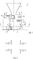
- the machine is placed on machine feet 3, here four machine feet 3a, b, c, d at each corner of the housing.
- the machine feet 3 have adjusting elements 9, via which the height of the filling machine 1, ie the Height of a reference point, here the distance between reference point P1, P2, P3 can be adjusted to the machine base or ground 4.
- Fig. 1 As can be seen, the ground or machine base 4, as shown by the dashed lines, be inclined. Since the filling tube 6 or its central axis M must be arranged correctly at a certain height or to a subsequent attachment machine, the height b between the center axis of the filling tube 6 and the bottom 4 must be set exactly and adjusted on uneven ground. Also, a plant reference plane A, for example, a plane that is perpendicular to the longitudinal axis of the machine, for example, a plane that includes the surface 13 of the housing or a plane that is spanned by at least three corners at the bottom of the machine housing, for example, horizontal, ie be aligned perpendicular to the gravitation G.
- a plant reference plane A for example, a plane that is perpendicular to the longitudinal axis of the machine, for example, a plane that includes the surface 13 of the housing or a plane that is spanned by at least three corners at the bottom of the machine housing, for example, horizontal, ie be
- the middle axis M of the filling tube 6 should advantageously lie in a corresponding plane which is perpendicular to the gravitational vector and should also be oriented perpendicular to the gravitational vector G or perpendicular to the longitudinal axis L of the filling machine.
- the filling machine should be placed inclined to a horizontal plane, as will be explained in more detail below.
- the filling machine has a calculation unit 10 in which measured values relating to the actual state of the height and / or the inclination and values relating to the desired state of the height and / or inclination can be stored.
- At least one measuring device 7 for measuring the height of the filling machine, at least one measuring device 7, in particular in the form of a distance sensor, can be provided, which can measure the distance from a reference point P1, P2, P3 to the machine base 4.
- Fig. 1 only the distance sensors 7a, 7b are shown by way of example, whereby corresponding distance sensors may also be located in the corner regions at the feet 3d and 3c in this embodiment.
- Corresponding distance measurement values a here for example measure the distance between the machine floor 14 and the machine base 4 are forwarded to the computing device 10.
- a distance meter 7 can also be provided in the region of the filling tube 6, via which the distance b between the central axis m of the filling tube and the machine base 4 is measured and forwarded to the calculating device 10.
- the calculation device 10 can determine, based on a desired-actual state comparison, whether the filling tube 6 is in a correct position.
- the reference point P of the measurement is irrelevant since, due to the known dimensions of the filling machine, it can also be measured starting from other measuring points, e.g. P1, P2, the position of the center axis of the filling tube can be determined or calculated.
- the distance sensors used are, for example, optical sensors or a device for distance measurement on the basis of travel time measurement and / or reflection (for example infrared, laser, sound, ultrasound), but also a force-sensitive and / or spring-actuated sensor / button can be used. Furthermore, the corresponding height can be measured not only via an electronic measuring device but also manually by means of a meter bar, yardstick, etc., and input via a schematically represented input unit 8 and transmitted to the calculation unit 10.
- the filling machine 1 preferably comprises an integrated tilt sensor 5, which transmits corresponding measured values to the calculation device 10.
- the inclination sensor is not integrated in the filling machine, but an external inclination measuring device (not shown) is provided, which is for example applied to the surface 13 or to a side wall of the filling machine 1, and the detected measured values with respect to the inclination to the computing device 10 either via cable or radio link Bluetooth, etc. forwards.
- the measured values generated by the external inclination measuring device to be input by the operator via an input unit 8 and thus stored in the calculating device 10.
- Suitable here are, for example, microelectromechanical spring-mass systems, devices for pressure measurement at several contact points, here pressure measurement on the foot surfaces facing the machine base 4, optical measuring devices, in particular camera, laser tracking, optical solder, laser plummet, gyroscope / gyro instrument, strain gauges / Force transducers attached to the filling machine and the actual position and Detect the position of the filling machine.
- devices for inductive or capacitive measurement can be provided, which are attached to the filling machine and detect the position and position of the filling machine by distance measurement.
- the inclination can also be determined via at least three distance sensors, which are preferably in a plane perpendicular to the longitudinal axis L, and measure the distance to the bottom 4, for example, the distance sensors 7 a, b, (c, d not shown) in the four corners the filling machine.
- concrete recommendations for action can be given and displayed to adjust the setting elements (for example thread turns) and thus to change the orientation of the filling machine and to bring into the desired condition.
- a further expansion stage may be to realize the adjustment of the machine orientation automatically via previously described drives, then the implementation of a control is advantageous.
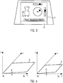
- Fig. 3 shows, for example, the measured height b of the filling machine, as well as a representation of the measured slope over two mutually perpendicular bars - according to the display of an electronic spirit level.
- b target 105 cm
- b actual 103 cm
- ⁇ 1 °
- ⁇ 0.5 °
- a foot 3a 20 cm
- a foot 3b 18 cm
- a foot 3c 21 cm
- a foot 3d 20.5 cm.
- the adjustment is not manual, but via a drive, as described above.
- either the operator can actuate the drive, which also here as described above, comes to a feedback when the actual position of the machine base 3 is reached, or it can be done an automatic control of the drive, so that the adjustment of the machine feet 3 takes place automatically via a control device. If the filling machine 1 as a whole is correctly aligned, ie tuning the inclination and height, this can also be displayed visually or acoustically accordingly.
- the distance sensors for checking the adjustment of the individual machine feet and be determined for example by signals of the drive by what amount .DELTA.l the respective foot has been adjusted.
- the orientation of the filling machine can be done, for example, the first time a filling machine 1 in a production environment, after the implementation of a filling machine within a production environment, as well as the adjustment of the machine height due to divergent requirements, for example, for connecting various attachment machines or ergonomic considerations.
- the computing device calculates on the basis of the deviation between actual and desired state, by what amount and in which direction the filling machine has to be adjusted by respectively ⁇ a via the adjustable machine feet, and according to a preferred embodiment, like corresponding adjusting elements 9 must be adjusted to achieve the desired state of height and / or inclination, in which case it is determined in particular by what amount and in which direction the machine feet of the filling machine must be adjusted in height.
- a recommendation for action can be displayed on the display 2, which indicates at least in which direction and preferably by what amount the machine feet each have to be adjusted in height.
- the calculation device can also forward signals to controls that drive the drives of the setting devices of the machine feet according to the calculation.
- the alignment procedure starts again to check if the adjustment was successful. If it then appears that the actual state corresponds to the desired state, the method is ended. Otherwise, the process loop will be run through again.
Landscapes
- Life Sciences & Earth Sciences (AREA)
- Engineering & Computer Science (AREA)
- Wood Science & Technology (AREA)
- Zoology (AREA)
- Food Science & Technology (AREA)
- Length Measuring Devices By Optical Means (AREA)
Claims (16)
- Procédé d'alignement d'une machine de remplissage (1), en particulier destinée à fabriquer des saucisses, le procédé étant caractérisé par les étapes suivantes :a) mesure de la hauteur (a, b) et/ou de l'inclinaison d'une machine de remplissage (1) dans une situation effective,b) transmission de la ou des valeurs de mesure à une unité de calcul (10),c) comparaison par l'unité de calcul (10) de la situation effective en hauteur et/ou en inclinaison à une situation de consigne en hauteur et/ou en inclinaison etd) ajustement de la hauteur (a, b) et/ou de l'inclinaison sur la base de la comparaison effectuée à l'étape c).
- Procédé selon la revendication 1, caractérisé en ce qu'à l'étape c), on calcule sur la base d'un écart entre la situation effective et la situation de consigne comment la machine de remplissage doit être alignée par des éléments appropriés d'ajustement (9) pour atteindre la situation de consigne en hauteur et/ou en inclinaison, et en particulier dans quelle direction et de quelle valeur (Δa) la machine de remplissage doit être ajustée en hauteur par l'intermédiaire des différents pieds (3) de la machine.
- Procédé selon les revendications 1 ou 2, caractérisé en ce qu'après l'étape c) a lieu un affichage qui indique l'écart entre la situation effective et la situation de consigne et/ou qui affiche une recommandation de manipulation d'ajustement d'éléments appropriés d'ajustement (9), en particulier pour l'ajustement en hauteur des pieds (3a, b, c, d) de la machine de remplissage (1), au moins la direction dans laquelle les différents pieds de la machine doivent être ajustés étant indiquée.
- Procédé selon les revendications 1, 2 ou 3, caractérisé en ce que pour ajuster la hauteur et/ou l'inclinaison à l'étape d), des entraînements des éléments d'ajustement (9) assurant l'ajustement en hauteur des pieds (3) de la machine de remplissage sont commandés automatiquement.
- Procédé selon au moins l'une des revendications 1 à 4, caractérisé en ce qu'après l'étape d), les étapes a) à c) sont de nouveau exécutées.
- Procédé selon au moins l'une des revendications 1 à 5, caractérisé en ce que lorsque la situation de consigne en hauteur et/ou en inclinaison est atteinte, un affichage optique et/ou acoustique a lieu et en particulier un affichage optique et/ou acoustique a lieu si un élément d'ajustement (9) a été ajusté correctement de telle sorte que la machine de remplissage ait été déplacée de la valeur correcte (Δa) dans la direction correcte par l'élément d'ajustement concerné.
- Procédé selon au moins l'une des revendications 1 à 6, caractérisé en ce que la situation effective en hauteur et/ou en inclinaison est déterminée par des valeurs de mesure provenant d'au moins un dispositif de mesure (5, 7) intégré dans la machine de remplissage (1) et/ou par l'intermédiaire de valeurs de mesure d'un dispositif de mesure externe.
- Procédé selon au moins l'une des revendications 1 à 7, caractérisé en ce que des valeurs concernant la situation de consigne en hauteur et/ou en inclinaison sont introduites dans le dispositif de calcul (10).
- Procédé selon au moins l'une des revendications 1 à 8, caractérisé en ce que la situation de consigne peut être au moins l'une des situations suivantes :- la hauteur d'au moins un point de référence (P) de l'installation,- un plan orienté horizontalement de l'installation (Asoll),- un plan de référence d'installation (Asoll) incliné par rapport à un plan horizontal.
- Machine de remplissage (1), en particulier destinée à mettre en oeuvre le procédé selon au moins l'une des revendications 1 à 9, et présentant un boîtier de machine (12), un entonnoir de remplissage (11), un tube de remplissage (6) et des pieds de machine (3),
caractérisée en ce que
la machine de remplissage (1) présente une unité de calcul (10) dans laquelle des valeurs de mesure concernant la situation effective en hauteur et/ou en inclinaison ainsi que des valeurs concernant la situation de consigne en hauteur et/ou en inclinaison peuvent être introduites,
l'unité de calcul (10) comportant un dispositif de comparaison qui compare la situation effective à la situation de consigne en hauteur et/ou en inclinaison et
au moins un élément d'ajustement (9) pouvant être ajusté sur la base de comparaison entre la situation effective et la situation de consigne. - Machine de remplissage selon la revendication 10, caractérisée en ce que le dispositif de calcul est configuré de manière à pouvoir calculer comment la machine de remplissage doit être alignée par des éléments d'ajustement (9) appropriés sur la base d'un écart entre la situation effective et la situation de consigne pour atteindre la situation de consigne en hauteur et/ou en inclinaison, et en particulier dans quelle direction et de quelle valeur (Δa) la machine de remplissage doit être ajustée en hauteur par l'intermédiaire des différents pieds (3) de la machine, et calcule en particulier comment des éléments d'ajustement (9) appropriés doivent être ajustés pour atteindre la situation de consigne en hauteur et/ou en inclinaison et en particulier dans quelle direction et avantageusement de quelle ampleur les pieds (3) de la machine de remplissage doivent être ajustés en hauteur.
- Machine de remplissage selon les revendications 10 ou 11, caractérisée en ce que la machine de remplissage (1) présente un affichage (2) qui indique l'écart entre la situation effective et la situation de consigne et/ou qui fournit une recommandation de manipulation en vue d'ajuster des éléments d'ajustement (9) appropriés, en particulier pour l'ajustement en hauteur des pieds de la machine de remplissage.
- Machine de remplissage selon au moins l'une des revendications 10 à 12, caractérisée en ce qu'au moins un élément d'ajustement comporte un entraînement qui est commandé en particulier automatiquement par le dispositif de calcul (10) jusqu'à ce qu'une valeur de consigne appropriée soit atteinte.
- Machine de remplissage selon au moins l'une des revendications 10 à 13, caractérisée en ce que la machine de remplissage comporte un affichage optique et/ou acoustique qui indique si la situation de consigne en hauteur et/ou en inclinaison est atteinte et/ou qui indique si un élément d'ajustement a été ajusté correctement de telle sorte que la machine de remplissage ait été déplacée de la valeur correcte (Δa) dans la direction correcte par l'élément d'ajustement concerné.
- Machine de remplissage selon au moins l'une des revendications 10 à 14, caractérisée en ce que la machine de remplissage (1) comporte au moins un dispositif de mesure (7, 5) qui saisit la situation effective en hauteur et/ou en inclinaison et/ou un dispositif d'introduction (8) qui permet d'introduire des valeurs de mesure en hauteur et/ou en inclinaison de la situation effective.
- Machine de remplissage selon au moins l'une des revendications 10 à 15, caractérisée en ce que pour mesurer la situation effective en hauteur et/ou en inclinaison, le dispositif de mesure présente au moins un capteur, de préférence un capteur de distance (7), en particulier en différents sommets de la machine de remplissage.
Priority Applications (4)
| Application Number | Priority Date | Filing Date | Title |
|---|---|---|---|
| EP15179017.7A EP3123867B1 (fr) | 2015-07-30 | 2015-07-30 | Procede et dispositif d'orientation simplifiee d'une machine de remplissage pour la fabrication de saucisses |
| ES15179017.7T ES2660477T3 (es) | 2015-07-30 | 2015-07-30 | Procedimiento y dispositivo para la nivelación simplificada de una máquina de llenado para la fabricación de embutidos |
| US15/220,206 US9723848B2 (en) | 2015-07-30 | 2016-07-26 | Method and device for simplified alignment of a filling machine for sausage production |
| CN201610605147.2A CN106386992A (zh) | 2015-07-30 | 2016-07-27 | 用于使香肠生产用的灌装机的调准简化的方法和装置 |
Applications Claiming Priority (1)
| Application Number | Priority Date | Filing Date | Title |
|---|---|---|---|
| EP15179017.7A EP3123867B1 (fr) | 2015-07-30 | 2015-07-30 | Procede et dispositif d'orientation simplifiee d'une machine de remplissage pour la fabrication de saucisses |
Publications (2)
| Publication Number | Publication Date |
|---|---|
| EP3123867A1 EP3123867A1 (fr) | 2017-02-01 |
| EP3123867B1 true EP3123867B1 (fr) | 2017-12-20 |
Family
ID=53765125
Family Applications (1)
| Application Number | Title | Priority Date | Filing Date |
|---|---|---|---|
| EP15179017.7A Active EP3123867B1 (fr) | 2015-07-30 | 2015-07-30 | Procede et dispositif d'orientation simplifiee d'une machine de remplissage pour la fabrication de saucisses |
Country Status (4)
| Country | Link |
|---|---|
| US (1) | US9723848B2 (fr) |
| EP (1) | EP3123867B1 (fr) |
| CN (1) | CN106386992A (fr) |
| ES (1) | ES2660477T3 (fr) |
Family Cites Families (21)
| Publication number | Priority date | Publication date | Assignee | Title |
|---|---|---|---|---|
| US4558488A (en) * | 1983-07-19 | 1985-12-17 | Teepak, Inc. | Size control system for automatic sausage stuffing |
| US4621482A (en) * | 1985-04-18 | 1986-11-11 | Naturin-Werk Becker & Co. | Method and apparatus for forming netted meat products wrapped in an edible collagen film |
| DE3545673C2 (de) * | 1985-12-21 | 1995-12-21 | Schnell Maschfab Karl | Portioniermaschine |
| DE3601313A1 (de) * | 1986-01-17 | 1987-07-23 | Handtmann Albert Maschf | Maschine zum fuellen von behaeltern oder daermen mit wurstbraet |
| US4773128A (en) * | 1987-01-13 | 1988-09-27 | Teepak, Inc. | Apparatus and methods of stuffing food casings to provide dimensionally uniform products |
| US4709450A (en) * | 1987-01-13 | 1987-12-01 | Teepak, Inc. | Apparatus and methods of stuffing food casings to provide dimensionally uniform products |
| US4766645A (en) * | 1987-04-16 | 1988-08-30 | Viskase Corporation | Size control system for stuffing machine |
| US4766713A (en) * | 1987-07-27 | 1988-08-30 | Delaware Capital Formation, Inc. | Packaging device including dual clip attachment apparatus, a casing brake mechanism and gathering mechanism |
| US4837897A (en) * | 1988-04-18 | 1989-06-13 | Viskase Corporation | Apparatus for monitoring the width of a stuffed food casing |
| CN2080308U (zh) * | 1990-12-24 | 1991-07-10 | 北京市熟肉制品加工厂 | 齿轮灌肠机 |
| CN2223559Y (zh) * | 1995-02-18 | 1996-04-03 | 广东省番禺市恒联食品机械厂 | 灌肠器械 |
| DE19726238C1 (de) * | 1997-06-20 | 1999-01-14 | Handtmann Albert Maschf | Verfahren und Vorrichtung zum Befüllen von Wursthüllen |
| US6245369B1 (en) * | 1999-07-14 | 2001-06-12 | Townsend Engineering Company | Method and means for controlling the variations in weight of extruded sausages |
| US6248013B1 (en) * | 1999-09-30 | 2001-06-19 | Ak Robins, Llc | Apparatus for processing meat |
| DE10013036A1 (de) * | 2000-03-17 | 2001-09-27 | Vemag Maschinenbau Gmbh | Verfahren und Vorrichtung zum Fördern und Vereinzeln von Würstchen oder dgl. |
| DE10033494C2 (de) * | 2000-07-10 | 2003-06-26 | Handtmann Albert Maschf | Verfahren und Vorrichtung zur Lageänderung von Wurstketten |
| DE10224123B4 (de) * | 2002-05-29 | 2005-03-31 | Mettler-Toledo Gmbh | Vorrichtung zur Betriebszustandsüberwachung für eine Waage |
| DE202004007711U1 (de) * | 2004-05-13 | 2004-08-12 | Tipper Tie Technopack Gmbh | Wurstverpackungsvorrichtung zum Befüllen von pastösem Füllgut in schlauchförmiges Hüllenmaterial |
| EP1672122A1 (fr) * | 2004-12-17 | 2006-06-21 | Leica Geosystems AG | Procédé et appareil pour contrôler une machine de construction de chaussée |
| DE112006004097C5 (de) * | 2006-11-03 | 2017-11-02 | Trimble Kaiserslautern Gmbh | Winkelmessgerät |
| CN101551241A (zh) * | 2009-05-04 | 2009-10-07 | 齐齐哈尔轨道交通装备有限责任公司 | 一种集装箱平车锁座平面度检测方法、系统及装置 |
-
2015
- 2015-07-30 EP EP15179017.7A patent/EP3123867B1/fr active Active
- 2015-07-30 ES ES15179017.7T patent/ES2660477T3/es active Active
-
2016
- 2016-07-26 US US15/220,206 patent/US9723848B2/en active Active
- 2016-07-27 CN CN201610605147.2A patent/CN106386992A/zh active Pending
Non-Patent Citations (1)
| Title |
|---|
| None * |
Also Published As
| Publication number | Publication date |
|---|---|
| CN106386992A (zh) | 2017-02-15 |
| ES2660477T3 (es) | 2018-03-22 |
| US20170027182A1 (en) | 2017-02-02 |
| EP3123867A1 (fr) | 2017-02-01 |
| US9723848B2 (en) | 2017-08-08 |
Similar Documents
| Publication | Publication Date | Title |
|---|---|---|
| DE102014015335B4 (de) | Generative Fertigungsvorrichtung und Fertigungsverfahren zm schichtweisen Aufbau von Bauwerken | |
| DE3120010C2 (fr) | ||
| EP3699357B1 (fr) | Train de travaux, comprenant une machine autopropulsée de traitement du sol et au moins un autre véhicule autopropulsé, avec une surveillance automatisée des distances | |
| EP2623677B1 (fr) | Procédé et agencement destinés à la fabrication d'un élément de paroi moulée | |
| DE102010004517B4 (de) | Optisches Instrument mit Winkelanzeige und Verfahren zum Betreiben desselben | |
| DE102016012065B4 (de) | Robotersystem mit Funktion zum Berechnen von Position und Ausrichtung eines Sensors | |
| EP2944171B1 (fr) | Machine agricole | |
| EP2927372A1 (fr) | Engin automobile et procédé de commande d'un engin automobile | |
| EP3439834B1 (fr) | Commande cartésienne d'une pointe de mât d'un manipulateur de grande dimension, en particulier une pompe à béton | |
| EP2997328B1 (fr) | Dispositif de nivellement de remblais et de matériaux de construction | |
| WO2015032864A1 (fr) | Détermination de la position d'un point de mesure mobile sur une machine | |
| EP3199486A1 (fr) | Mécanisme de grue et plate-forme de travail avec un dispositif de détection de charge et un capteur d'inclinaison intégré | |
| EP2408590B1 (fr) | Procédé et dispositif pour installer une machine | |
| DE112018005783T5 (de) | Hauptform- und Kernverbindungsvorrichtung und Hauptform- und Kernverbindungsverfahren | |
| EP3191236B1 (fr) | Presse plieuse et procédé de pliage d'une pièce à l'aide de la presse plieuse | |
| EP2605995B1 (fr) | Procédé et dispositif pour la détermination d'une hauteur de course d'une machine de travail | |
| DE102005022231B4 (de) | Verfahren und Vorrichtung zur Darstellung des Lage und des Bewegungszustands einer pendelfähigen Last | |
| EP2277004A1 (fr) | Système de mesure mobile et procédé de mesure permettant de déterminer des sections transversales ou des contours | |
| EP2789971A1 (fr) | Procédé de calibrage d'un dispositif de détection et dispositif de détection | |
| EP2574412A1 (fr) | Capteur de mesure, système de mesure, procédé d'établissement par laser optique de la position en hauteur d'un cylindre de corset de guidage et utilisation du système de mesure | |
| EP3037780A1 (fr) | Procédé destiné à la détection d'une plage de mesure dans un support | |
| EP3123867A1 (fr) | Procede et dispositif d'orientation simplifiee d'une machine de remplissage pour la fabrication de saucisses | |
| EP4201621B1 (fr) | Construction d'un coffrage | |
| EP3670747B1 (fr) | Engin de construction autonome et procédé d'usinage d'un revêtement de sol | |
| EP2407261B1 (fr) | Procédé de mesure de reconnaissance de palier automatique d'une busette de coulée d'un récipient métallurgique |
Legal Events
| Date | Code | Title | Description |
|---|---|---|---|
| PUAI | Public reference made under article 153(3) epc to a published international application that has entered the european phase |
Free format text: ORIGINAL CODE: 0009012 |
|
| 17P | Request for examination filed |
Effective date: 20160615 |
|
| AK | Designated contracting states |
Kind code of ref document: A1 Designated state(s): AL AT BE BG CH CY CZ DE DK EE ES FI FR GB GR HR HU IE IS IT LI LT LU LV MC MK MT NL NO PL PT RO RS SE SI SK SM TR |
|
| AX | Request for extension of the european patent |
Extension state: BA ME |
|
| RIC1 | Information provided on ipc code assigned before grant |
Ipc: A22C 11/02 20060101AFI20170519BHEP |
|
| GRAP | Despatch of communication of intention to grant a patent |
Free format text: ORIGINAL CODE: EPIDOSNIGR1 |
|
| INTG | Intention to grant announced |
Effective date: 20170706 |
|
| GRAS | Grant fee paid |
Free format text: ORIGINAL CODE: EPIDOSNIGR3 |
|
| GRAA | (expected) grant |
Free format text: ORIGINAL CODE: 0009210 |
|
| AK | Designated contracting states |
Kind code of ref document: B1 Designated state(s): AL AT BE BG CH CY CZ DE DK EE ES FI FR GB GR HR HU IE IS IT LI LT LU LV MC MK MT NL NO PL PT RO RS SE SI SK SM TR |
|
| REG | Reference to a national code |
Ref country code: GB Ref legal event code: FG4D Free format text: NOT ENGLISH |
|
| REG | Reference to a national code |
Ref country code: CH Ref legal event code: EP |
|
| REG | Reference to a national code |
Ref country code: IE Ref legal event code: FG4D Free format text: LANGUAGE OF EP DOCUMENT: GERMAN |
|
| REG | Reference to a national code |
Ref country code: AT Ref legal event code: REF Ref document number: 955529 Country of ref document: AT Kind code of ref document: T Effective date: 20180115 |
|
| REG | Reference to a national code |
Ref country code: DE Ref legal event code: R096 Ref document number: 502015002617 Country of ref document: DE |
|
| REG | Reference to a national code |
Ref country code: NL Ref legal event code: FP |
|
| REG | Reference to a national code |
Ref country code: ES Ref legal event code: FG2A Ref document number: 2660477 Country of ref document: ES Kind code of ref document: T3 Effective date: 20180322 |
|
| PG25 | Lapsed in a contracting state [announced via postgrant information from national office to epo] |
Ref country code: NO Free format text: LAPSE BECAUSE OF FAILURE TO SUBMIT A TRANSLATION OF THE DESCRIPTION OR TO PAY THE FEE WITHIN THE PRESCRIBED TIME-LIMIT Effective date: 20180320 Ref country code: LT Free format text: LAPSE BECAUSE OF FAILURE TO SUBMIT A TRANSLATION OF THE DESCRIPTION OR TO PAY THE FEE WITHIN THE PRESCRIBED TIME-LIMIT Effective date: 20171220 Ref country code: SE Free format text: LAPSE BECAUSE OF FAILURE TO SUBMIT A TRANSLATION OF THE DESCRIPTION OR TO PAY THE FEE WITHIN THE PRESCRIBED TIME-LIMIT Effective date: 20171220 Ref country code: FI Free format text: LAPSE BECAUSE OF FAILURE TO SUBMIT A TRANSLATION OF THE DESCRIPTION OR TO PAY THE FEE WITHIN THE PRESCRIBED TIME-LIMIT Effective date: 20171220 |
|
| REG | Reference to a national code |
Ref country code: LT Ref legal event code: MG4D |
|
| PG25 | Lapsed in a contracting state [announced via postgrant information from national office to epo] |
Ref country code: HR Free format text: LAPSE BECAUSE OF FAILURE TO SUBMIT A TRANSLATION OF THE DESCRIPTION OR TO PAY THE FEE WITHIN THE PRESCRIBED TIME-LIMIT Effective date: 20171220 Ref country code: GR Free format text: LAPSE BECAUSE OF FAILURE TO SUBMIT A TRANSLATION OF THE DESCRIPTION OR TO PAY THE FEE WITHIN THE PRESCRIBED TIME-LIMIT Effective date: 20180321 Ref country code: RS Free format text: LAPSE BECAUSE OF FAILURE TO SUBMIT A TRANSLATION OF THE DESCRIPTION OR TO PAY THE FEE WITHIN THE PRESCRIBED TIME-LIMIT Effective date: 20171220 Ref country code: LV Free format text: LAPSE BECAUSE OF FAILURE TO SUBMIT A TRANSLATION OF THE DESCRIPTION OR TO PAY THE FEE WITHIN THE PRESCRIBED TIME-LIMIT Effective date: 20171220 Ref country code: BG Free format text: LAPSE BECAUSE OF FAILURE TO SUBMIT A TRANSLATION OF THE DESCRIPTION OR TO PAY THE FEE WITHIN THE PRESCRIBED TIME-LIMIT Effective date: 20180320 |
|
| REG | Reference to a national code |
Ref country code: FR Ref legal event code: PLFP Year of fee payment: 4 |
|
| PG25 | Lapsed in a contracting state [announced via postgrant information from national office to epo] |
Ref country code: EE Free format text: LAPSE BECAUSE OF FAILURE TO SUBMIT A TRANSLATION OF THE DESCRIPTION OR TO PAY THE FEE WITHIN THE PRESCRIBED TIME-LIMIT Effective date: 20171220 Ref country code: CY Free format text: LAPSE BECAUSE OF FAILURE TO SUBMIT A TRANSLATION OF THE DESCRIPTION OR TO PAY THE FEE WITHIN THE PRESCRIBED TIME-LIMIT Effective date: 20171220 Ref country code: SK Free format text: LAPSE BECAUSE OF FAILURE TO SUBMIT A TRANSLATION OF THE DESCRIPTION OR TO PAY THE FEE WITHIN THE PRESCRIBED TIME-LIMIT Effective date: 20171220 Ref country code: CZ Free format text: LAPSE BECAUSE OF FAILURE TO SUBMIT A TRANSLATION OF THE DESCRIPTION OR TO PAY THE FEE WITHIN THE PRESCRIBED TIME-LIMIT Effective date: 20171220 |
|
| PG25 | Lapsed in a contracting state [announced via postgrant information from national office to epo] |
Ref country code: PL Free format text: LAPSE BECAUSE OF FAILURE TO SUBMIT A TRANSLATION OF THE DESCRIPTION OR TO PAY THE FEE WITHIN THE PRESCRIBED TIME-LIMIT Effective date: 20171220 Ref country code: SM Free format text: LAPSE BECAUSE OF FAILURE TO SUBMIT A TRANSLATION OF THE DESCRIPTION OR TO PAY THE FEE WITHIN THE PRESCRIBED TIME-LIMIT Effective date: 20171220 Ref country code: IS Free format text: LAPSE BECAUSE OF FAILURE TO SUBMIT A TRANSLATION OF THE DESCRIPTION OR TO PAY THE FEE WITHIN THE PRESCRIBED TIME-LIMIT Effective date: 20180420 |
|
| REG | Reference to a national code |
Ref country code: DE Ref legal event code: R097 Ref document number: 502015002617 Country of ref document: DE |
|
| PG25 | Lapsed in a contracting state [announced via postgrant information from national office to epo] |
Ref country code: MT Free format text: LAPSE BECAUSE OF FAILURE TO SUBMIT A TRANSLATION OF THE DESCRIPTION OR TO PAY THE FEE WITHIN THE PRESCRIBED TIME-LIMIT Effective date: 20171220 |
|
| PLBE | No opposition filed within time limit |
Free format text: ORIGINAL CODE: 0009261 |
|
| STAA | Information on the status of an ep patent application or granted ep patent |
Free format text: STATUS: NO OPPOSITION FILED WITHIN TIME LIMIT |
|
| PG25 | Lapsed in a contracting state [announced via postgrant information from national office to epo] |
Ref country code: DK Free format text: LAPSE BECAUSE OF FAILURE TO SUBMIT A TRANSLATION OF THE DESCRIPTION OR TO PAY THE FEE WITHIN THE PRESCRIBED TIME-LIMIT Effective date: 20171220 |
|
| 26N | No opposition filed |
Effective date: 20180921 |
|
| PG25 | Lapsed in a contracting state [announced via postgrant information from national office to epo] |
Ref country code: SI Free format text: LAPSE BECAUSE OF FAILURE TO SUBMIT A TRANSLATION OF THE DESCRIPTION OR TO PAY THE FEE WITHIN THE PRESCRIBED TIME-LIMIT Effective date: 20171220 |
|
| REG | Reference to a national code |
Ref country code: CH Ref legal event code: PL |
|
| PG25 | Lapsed in a contracting state [announced via postgrant information from national office to epo] |
Ref country code: MC Free format text: LAPSE BECAUSE OF FAILURE TO SUBMIT A TRANSLATION OF THE DESCRIPTION OR TO PAY THE FEE WITHIN THE PRESCRIBED TIME-LIMIT Effective date: 20171220 Ref country code: LU Free format text: LAPSE BECAUSE OF NON-PAYMENT OF DUE FEES Effective date: 20180730 |
|
| REG | Reference to a national code |
Ref country code: BE Ref legal event code: MM Effective date: 20180731 |
|
| PG25 | Lapsed in a contracting state [announced via postgrant information from national office to epo] |
Ref country code: LI Free format text: LAPSE BECAUSE OF NON-PAYMENT OF DUE FEES Effective date: 20180731 Ref country code: CH Free format text: LAPSE BECAUSE OF NON-PAYMENT OF DUE FEES Effective date: 20180731 |
|
| REG | Reference to a national code |
Ref country code: IE Ref legal event code: MM4A |
|
| PG25 | Lapsed in a contracting state [announced via postgrant information from national office to epo] |
Ref country code: BE Free format text: LAPSE BECAUSE OF NON-PAYMENT OF DUE FEES Effective date: 20180731 |
|
| PG25 | Lapsed in a contracting state [announced via postgrant information from national office to epo] |
Ref country code: IE Free format text: LAPSE BECAUSE OF NON-PAYMENT OF DUE FEES Effective date: 20180730 |
|
| GBPC | Gb: european patent ceased through non-payment of renewal fee |
Effective date: 20190730 |
|
| PG25 | Lapsed in a contracting state [announced via postgrant information from national office to epo] |
Ref country code: TR Free format text: LAPSE BECAUSE OF FAILURE TO SUBMIT A TRANSLATION OF THE DESCRIPTION OR TO PAY THE FEE WITHIN THE PRESCRIBED TIME-LIMIT Effective date: 20171220 |
|
| PG25 | Lapsed in a contracting state [announced via postgrant information from national office to epo] |
Ref country code: GB Free format text: LAPSE BECAUSE OF NON-PAYMENT OF DUE FEES Effective date: 20190730 |
|
| PG25 | Lapsed in a contracting state [announced via postgrant information from national office to epo] |
Ref country code: PT Free format text: LAPSE BECAUSE OF FAILURE TO SUBMIT A TRANSLATION OF THE DESCRIPTION OR TO PAY THE FEE WITHIN THE PRESCRIBED TIME-LIMIT Effective date: 20171220 |
|
| PG25 | Lapsed in a contracting state [announced via postgrant information from national office to epo] |
Ref country code: MK Free format text: LAPSE BECAUSE OF NON-PAYMENT OF DUE FEES Effective date: 20171220 Ref country code: RO Free format text: LAPSE BECAUSE OF FAILURE TO SUBMIT A TRANSLATION OF THE DESCRIPTION OR TO PAY THE FEE WITHIN THE PRESCRIBED TIME-LIMIT Effective date: 20171220 Ref country code: HU Free format text: LAPSE BECAUSE OF FAILURE TO SUBMIT A TRANSLATION OF THE DESCRIPTION OR TO PAY THE FEE WITHIN THE PRESCRIBED TIME-LIMIT; INVALID AB INITIO Effective date: 20150730 |
|
| PG25 | Lapsed in a contracting state [announced via postgrant information from national office to epo] |
Ref country code: AL Free format text: LAPSE BECAUSE OF FAILURE TO SUBMIT A TRANSLATION OF THE DESCRIPTION OR TO PAY THE FEE WITHIN THE PRESCRIBED TIME-LIMIT Effective date: 20171220 |
|
| P01 | Opt-out of the competence of the unified patent court (upc) registered |
Effective date: 20230523 |
|
| PGFP | Annual fee paid to national office [announced via postgrant information from national office to epo] |
Ref country code: NL Payment date: 20240726 Year of fee payment: 10 |
|
| PGFP | Annual fee paid to national office [announced via postgrant information from national office to epo] |
Ref country code: DE Payment date: 20240729 Year of fee payment: 10 |
|
| PGFP | Annual fee paid to national office [announced via postgrant information from national office to epo] |
Ref country code: FR Payment date: 20240724 Year of fee payment: 10 |
|
| PGFP | Annual fee paid to national office [announced via postgrant information from national office to epo] |
Ref country code: ES Payment date: 20240801 Year of fee payment: 10 |
|
| PGFP | Annual fee paid to national office [announced via postgrant information from national office to epo] |
Ref country code: AT Payment date: 20240723 Year of fee payment: 10 |
|
| PGFP | Annual fee paid to national office [announced via postgrant information from national office to epo] |
Ref country code: IT Payment date: 20240729 Year of fee payment: 10 |
|
| REG | Reference to a national code |
Ref country code: DE Ref legal event code: R119 Ref document number: 502015002617 Country of ref document: DE |
|
| REG | Reference to a national code |
Ref country code: NL Ref legal event code: MM Effective date: 20250801 |
|
| REG | Reference to a national code |
Ref country code: AT Ref legal event code: MM01 Ref document number: 955529 Country of ref document: AT Kind code of ref document: T Effective date: 20250730 |
|
| PG25 | Lapsed in a contracting state [announced via postgrant information from national office to epo] |
Ref country code: DE Free format text: LAPSE BECAUSE OF NON-PAYMENT OF DUE FEES Effective date: 20260203 |
|
| PG25 | Lapsed in a contracting state [announced via postgrant information from national office to epo] |
Ref country code: AT Free format text: LAPSE BECAUSE OF NON-PAYMENT OF DUE FEES Effective date: 20250730 |
|
| PG25 | Lapsed in a contracting state [announced via postgrant information from national office to epo] |
Ref country code: NL Free format text: LAPSE BECAUSE OF NON-PAYMENT OF DUE FEES Effective date: 20250801 |
|
| PG25 | Lapsed in a contracting state [announced via postgrant information from national office to epo] |
Ref country code: FR Free format text: LAPSE BECAUSE OF NON-PAYMENT OF DUE FEES Effective date: 20250731 |