EP3123920A1 - Unité d'imagerie pour endoscopes - Google Patents
Unité d'imagerie pour endoscopes Download PDFInfo
- Publication number
- EP3123920A1 EP3123920A1 EP15768959.7A EP15768959A EP3123920A1 EP 3123920 A1 EP3123920 A1 EP 3123920A1 EP 15768959 A EP15768959 A EP 15768959A EP 3123920 A1 EP3123920 A1 EP 3123920A1
- Authority
- EP
- European Patent Office
- Prior art keywords
- acquisition
- frame
- image
- region
- objective
- Prior art date
- Legal status (The legal status is an assumption and is not a legal conclusion. Google has not performed a legal analysis and makes no representation as to the accuracy of the status listed.)
- Withdrawn
Links
- 238000003384 imaging method Methods 0.000 title 1
- 238000010521 absorption reaction Methods 0.000 claims abstract description 51
- 239000011347 resin Substances 0.000 claims abstract description 14
- 229920005989 resin Polymers 0.000 claims abstract description 14
- 229920001187 thermosetting polymer Polymers 0.000 claims abstract description 14
- 230000003746 surface roughness Effects 0.000 claims description 40
- 238000004519 manufacturing process Methods 0.000 abstract description 10
- 239000007769 metal material Substances 0.000 description 18
- 238000007747 plating Methods 0.000 description 12
- VYZAMTAEIAYCRO-UHFFFAOYSA-N Chromium Chemical compound [Cr] VYZAMTAEIAYCRO-UHFFFAOYSA-N 0.000 description 10
- 229910052804 chromium Inorganic materials 0.000 description 10
- 239000011651 chromium Substances 0.000 description 10
- 229910001220 stainless steel Inorganic materials 0.000 description 10
- 239000010935 stainless steel Substances 0.000 description 10
- 230000003287 optical effect Effects 0.000 description 9
- XEEYBQQBJWHFJM-UHFFFAOYSA-N Iron Chemical compound [Fe] XEEYBQQBJWHFJM-UHFFFAOYSA-N 0.000 description 8
- PXHVJJICTQNCMI-UHFFFAOYSA-N Nickel Chemical compound [Ni] PXHVJJICTQNCMI-UHFFFAOYSA-N 0.000 description 8
- 239000000853 adhesive Substances 0.000 description 6
- 230000001070 adhesive effect Effects 0.000 description 6
- 230000002093 peripheral effect Effects 0.000 description 6
- 239000011358 absorbing material Substances 0.000 description 5
- RYGMFSIKBFXOCR-UHFFFAOYSA-N Copper Chemical compound [Cu] RYGMFSIKBFXOCR-UHFFFAOYSA-N 0.000 description 4
- 229910052802 copper Inorganic materials 0.000 description 4
- 239000010949 copper Substances 0.000 description 4
- 238000010438 heat treatment Methods 0.000 description 4
- 229910052742 iron Inorganic materials 0.000 description 4
- 229910052759 nickel Inorganic materials 0.000 description 4
- 239000011295 pitch Substances 0.000 description 4
- 229910001369 Brass Inorganic materials 0.000 description 3
- 229910052782 aluminium Inorganic materials 0.000 description 3
- XAGFODPZIPBFFR-UHFFFAOYSA-N aluminium Chemical compound [Al] XAGFODPZIPBFFR-UHFFFAOYSA-N 0.000 description 3
- 239000010951 brass Substances 0.000 description 3
- ZCDOYSPFYFSLEW-UHFFFAOYSA-N chromate(2-) Chemical compound [O-][Cr]([O-])(=O)=O ZCDOYSPFYFSLEW-UHFFFAOYSA-N 0.000 description 3
- 230000000694 effects Effects 0.000 description 3
- 238000003754 machining Methods 0.000 description 3
- 239000003973 paint Substances 0.000 description 3
- WGLPBDUCMAPZCE-UHFFFAOYSA-N Trioxochromium Chemical compound O=[Cr](=O)=O WGLPBDUCMAPZCE-UHFFFAOYSA-N 0.000 description 2
- 229910000423 chromium oxide Inorganic materials 0.000 description 2
- 229940035427 chromium oxide Drugs 0.000 description 2
- 239000006059 cover glass Substances 0.000 description 2
- 230000003247 decreasing effect Effects 0.000 description 2
- 238000001035 drying Methods 0.000 description 2
- 230000001678 irradiating effect Effects 0.000 description 2
- 229910052751 metal Inorganic materials 0.000 description 2
- 239000002184 metal Substances 0.000 description 2
- ZOKXTWBITQBERF-UHFFFAOYSA-N Molybdenum Chemical compound [Mo] ZOKXTWBITQBERF-UHFFFAOYSA-N 0.000 description 1
- 238000001444 catalytic combustion detection Methods 0.000 description 1
- 239000000463 material Substances 0.000 description 1
- 229910044991 metal oxide Inorganic materials 0.000 description 1
- 150000004706 metal oxides Chemical class 0.000 description 1
- 230000004048 modification Effects 0.000 description 1
- 238000012986 modification Methods 0.000 description 1
- 229910052750 molybdenum Inorganic materials 0.000 description 1
- 239000011733 molybdenum Substances 0.000 description 1
- 239000000843 powder Substances 0.000 description 1
- 238000005488 sandblasting Methods 0.000 description 1
Images



Classifications
-
- A—HUMAN NECESSITIES
- A61—MEDICAL OR VETERINARY SCIENCE; HYGIENE
- A61B—DIAGNOSIS; SURGERY; IDENTIFICATION
- A61B1/00—Instruments for performing medical examinations of the interior of cavities or tubes of the body by visual or photographical inspection, e.g. endoscopes; Illuminating arrangements therefor
- A61B1/00163—Optical arrangements
-
- A—HUMAN NECESSITIES
- A61—MEDICAL OR VETERINARY SCIENCE; HYGIENE
- A61B—DIAGNOSIS; SURGERY; IDENTIFICATION
- A61B1/00—Instruments for performing medical examinations of the interior of cavities or tubes of the body by visual or photographical inspection, e.g. endoscopes; Illuminating arrangements therefor
- A61B1/00064—Constructional details of the endoscope body
- A61B1/00071—Insertion part of the endoscope body
- A61B1/0008—Insertion part of the endoscope body characterised by distal tip features
-
- A—HUMAN NECESSITIES
- A61—MEDICAL OR VETERINARY SCIENCE; HYGIENE
- A61B—DIAGNOSIS; SURGERY; IDENTIFICATION
- A61B1/00—Instruments for performing medical examinations of the interior of cavities or tubes of the body by visual or photographical inspection, e.g. endoscopes; Illuminating arrangements therefor
- A61B1/00064—Constructional details of the endoscope body
- A61B1/00071—Insertion part of the endoscope body
- A61B1/0008—Insertion part of the endoscope body characterised by distal tip features
- A61B1/00096—Optical elements
-
- A—HUMAN NECESSITIES
- A61—MEDICAL OR VETERINARY SCIENCE; HYGIENE
- A61B—DIAGNOSIS; SURGERY; IDENTIFICATION
- A61B1/00—Instruments for performing medical examinations of the interior of cavities or tubes of the body by visual or photographical inspection, e.g. endoscopes; Illuminating arrangements therefor
- A61B1/00064—Constructional details of the endoscope body
- A61B1/0011—Manufacturing of endoscope parts
-
- A—HUMAN NECESSITIES
- A61—MEDICAL OR VETERINARY SCIENCE; HYGIENE
- A61B—DIAGNOSIS; SURGERY; IDENTIFICATION
- A61B1/00—Instruments for performing medical examinations of the interior of cavities or tubes of the body by visual or photographical inspection, e.g. endoscopes; Illuminating arrangements therefor
- A61B1/04—Instruments for performing medical examinations of the interior of cavities or tubes of the body by visual or photographical inspection, e.g. endoscopes; Illuminating arrangements therefor combined with photographic or television appliances
- A61B1/044—Instruments for performing medical examinations of the interior of cavities or tubes of the body by visual or photographical inspection, e.g. endoscopes; Illuminating arrangements therefor combined with photographic or television appliances for absorption imaging
-
- A—HUMAN NECESSITIES
- A61—MEDICAL OR VETERINARY SCIENCE; HYGIENE
- A61B—DIAGNOSIS; SURGERY; IDENTIFICATION
- A61B1/00—Instruments for performing medical examinations of the interior of cavities or tubes of the body by visual or photographical inspection, e.g. endoscopes; Illuminating arrangements therefor
- A61B1/04—Instruments for performing medical examinations of the interior of cavities or tubes of the body by visual or photographical inspection, e.g. endoscopes; Illuminating arrangements therefor combined with photographic or television appliances
- A61B1/046—Instruments for performing medical examinations of the interior of cavities or tubes of the body by visual or photographical inspection, e.g. endoscopes; Illuminating arrangements therefor combined with photographic or television appliances for infrared imaging
-
- G—PHYSICS
- G02—OPTICS
- G02B—OPTICAL ELEMENTS, SYSTEMS OR APPARATUS
- G02B23/00—Telescopes, e.g. binoculars; Periscopes; Instruments for viewing the inside of hollow bodies; Viewfinders; Optical aiming or sighting devices
- G02B23/24—Instruments or systems for viewing the inside of hollow bodies, e.g. fibrescopes
- G02B23/2407—Optical details
- G02B23/2423—Optical details of the distal end
- G02B23/243—Objectives for endoscopes
-
- G—PHYSICS
- G02—OPTICS
- G02B—OPTICAL ELEMENTS, SYSTEMS OR APPARATUS
- G02B23/00—Telescopes, e.g. binoculars; Periscopes; Instruments for viewing the inside of hollow bodies; Viewfinders; Optical aiming or sighting devices
- G02B23/24—Instruments or systems for viewing the inside of hollow bodies, e.g. fibrescopes
- G02B23/2476—Non-optical details, e.g. housings, mountings, supports
- G02B23/2484—Arrangements in relation to a camera or imaging device
-
- A—HUMAN NECESSITIES
- A61—MEDICAL OR VETERINARY SCIENCE; HYGIENE
- A61B—DIAGNOSIS; SURGERY; IDENTIFICATION
- A61B1/00—Instruments for performing medical examinations of the interior of cavities or tubes of the body by visual or photographical inspection, e.g. endoscopes; Illuminating arrangements therefor
- A61B1/00064—Constructional details of the endoscope body
- A61B1/00071—Insertion part of the endoscope body
- A61B1/00075—Insertion part of the endoscope body with externally roughened shaft
Definitions
- the present invention relates to image-acquisition units that are applied to endoscopes.
- an endoscopic image-acquisition unit is configured such that an objective-lens-unit frame that holds an objective lens and an image-acquisition device are fitted and fixed together. More specifically, a thermosetting resin is applied to fitting regions of the objective-lens-unit frame and the image-acquisition-device holding frame, and with the optical axes of an objective optical system and an image-acquisition device oriented so as to achieve a desired focus, the frames are fixed together by using assembly jigs and are heated in a drying furnace, etc. Thus, the thermosetting resin is cured, whereby the objective-lens-unit frame and the image-acquisition-device holding frame are bonded to and fixed together.
- the present invention has been made in view of the situation described above, and an object thereof is to suppress manufacturing errors, thereby improving the precision of positioning between an image-acquisition device and an objective lens.
- the present invention employs the following solutions.
- an endoscopic image-acquisition unit including an objective-lens-unit frame that holds an objective lens; and an image-acquisition-device holding frame that is fitted with the objective-lens-unit frame and that holds an image-acquisition device, wherein the objective-lens-unit frame and the image-acquisition-device holding frame are bonded and fixed with a thermosetting resin that is applied to a fitting region of these frames, and wherein, of the outer surface of the frame that is located on the outer side when the objective-lens-unit frame and the image-acquisition-device holding frame are fitted together, the outer surface of the fitting region and the outer surface of the region other than the fitting region satisfy the following conditional expression: ⁇ / ⁇ > 2 where ⁇ signifies the infrared absorption rate per unit area of the outer surface of the fitting region, and ⁇ signifies the infrared absorption rate per unit area of the outer surface of the region other than the fitting region.
- the outer surface of the fitting region and the outer surface of the region other than the fitting region are configured to satisfy conditional expression (1).
- conditional expression (1) the infrared absorption rate is higher in the fitting region of the objective-lens-unit frame and the image-acquisition-device holding frame compared with the region other than the fitting region. That is, in this configuration, the fitting region of the objective-lens-unit frame and the image-acquisition-device holding frame is heated more easily by infrared irradiation compared with the region other than the fitting region.
- thermosetting resin to the fitting region of the objective-lens-unit frame and the image-acquisition-device holding frame, positioning and fixing these frames by using jigs, and irradiating the fitting region with infrared rays, it is possible to efficiently heat only the fitting region.
- conditional expression (2) may be satisfied: ⁇ / ⁇ > 4
- conditional expression (3) may be satisfied: Ra > 3 ⁇ Rb
- Ra signifies the maximum height of the surface roughness of the outer surface of the fitting region
- Rb signifies the maximum height of the surface roughness of the outer surface of the region other than the fitting region.
- the maximum height here refers to a value ( ⁇ m) indicating the difference between a maximum value and a minimum value of the surface roughness.
- an endoscopic image-acquisition unit including an objective-lens-unit frame that holds an objective lens; and an image-acquisition-device holding frame that is fitted with the objective-lens-unit frame and that holds an image-acquisition device, wherein the objective-lens-unit frame and the image-acquisition-device holding frame are bonded and fixed with a thermosetting resin that is applied to a fitting region of these frames, and wherein the outer surface of the frame that is located on the outer side when the objective-lens-unit frame and the image-acquisition-device holding frame are fitted together and the outer surface of the region other than the fitting region in the outer surface of the frame that is located on the inner side satisfy conditional expression (4) below: ⁇ / ⁇ > 1.5 where ⁇ signifies the infrared absorption rate per unit area of the outer surface of the frame that is located on the outer side, and ⁇ signifies the infrared absorption rate per unit area of the outer surface of the region other than the fitting region in the
- the outer surface of the frame that is located on the outer side when the objective-lens-unit frame and the image-acquisition-device holding frame are fitted together and the outer surface of the region other than the fitting region in the outer surface of the frame that is located on the inner side are configured to satisfy conditional expression (4), so that the infrared absorption rate is higher in the fitting region of the objective-lens-unit frame and the image-acquisition-device holding frame compared with the region other than the fitting region. That is, in this configuration, the fitting region of the objective-lens-unit frame and the image-acquisition-device holding frame is heated more easily by infrared irradiation compared with the region other than the fitting region.
- thermosetting resin to the fitting region of the objective-lens-unit frame and the image-acquisition-device holding frame, positioning and fixing these frames by using jigs, and irradiating the fitting region with infrared rays, it is possible to efficiently heat only the fitting region.
- thermosetting resin when curing the thermosetting resin, it suffices to irradiate the fitting region with infrared rays, and it is unnecessary to heat the entire objective-lens-unit frame and image-acquisition-device holding frame fixed together by using jigs. Furthermore, by increasing the infrared absorption rate of the fitting region such that the infrared absorption rate of the region other than the fitting region is lower compared with the fitting region, transfer of heat to the jigs is minimized. Accordingly, it is possible to suppress positional deviations due to thermal expansion of jigs and parts, which serves to suppress manufacturing errors, so that the precision of positioning between the objective lens and the image-acquisition device can be improved.
- conditional expression (5) may be satisfied: ⁇ / ⁇ > 2
- conditional expression (6) may be satisfied: Rbo > 3 ⁇ Rai
- Rai signifies the maximum height of the surface roughness of the outer surface of the region other than the fitting region in the outer surface of the frame that is located on the inner side
- Rbo signifies the maximum height of the surface roughness of the outer surface of the frame that is located on the outer side.
- the maximum height here refers to a value ( ⁇ m) indicating the difference between a maximum value and a minimum value of the surface roughness.
- conditional expression (7) may be satisfied: 2.5 ⁇ P ⁇ Fno ⁇ 0.03 where P signifies the pitch of the image-acquisition device, and Fno signifies the effective F number of the objective optical system.
- an advantage is afforded in that manufacturing errors are suppressed, so that the precision of positioning between an image-acquisition device and an objective lens is improved.
- the endoscopic image-acquisition unit includes an objective-lens-unit frame 2 that holds objective lenses and an image-acquisition-device holding frame 3 that is fitted with the objective-lens-unit frame 2 and that holds an image-acquisition device.
- This embodiment will be described assuming that the objective-lens-unit frame 2 is located on the inner side and the image-acquisition-device holding frame 3 is located on the outer side when these frames are fitted together.
- the objective-lens-unit frame 2 holds multiple lenses L1, L2, L3, and L4.
- an end region on the image-acquisition-surface side constitutes a fitting region 10 that is fitted with the image-acquisition-device holding frame 3.
- the image-acquisition-device holding frame 3 holds an image-acquisition device 4 and a cover glass plate 5.
- an end region on the object-surface side constitutes a fitting region 11 that is fitted with the objective-lens-unit frame 2.
- the outer surface of the fitting region 11 and the outer surface of the region other than the fitting region 11 are configured to satisfy the following conditional expression: ⁇ / ⁇ > 2 where ⁇ signifies the infrared absorption rate per unit area of the outer surface of the fitting region, and ⁇ signifies the infrared absorption rate per unit area of the outer surface of the region other than the fitting region.
- the image-acquisition-device holding frame 3 is made of a metallic material.
- the outer surface of the image-acquisition-device holding frame 3 is plated with chromium, and the outer surface of the region other than the fitting region 11 is not plated or otherwise treated, so that the machined surface of the metallic material is exposed, constituting a lustrous metallic surface. That is, of the outer surface of the image-acquisition-device holding frame 3, compared with the metallic surface of the outer surface of the region other than the fitting region 11, the outer surface of the fitting region 11 absorbs infrared rays more efficiently since it is chromium-plated and is black.
- the outer surface of the fitting region is labeled as " ⁇ region,” and the outer surface of the region other than the fitting region is labeled as " ⁇ region.”
- the infrared absorption rate per unit area of the outer surface (metallic surface) of the region other than the fitting region 11, which is not chromium-plated is about 7%.
- the infrared absorption rate per unit area of the outer surface of the fitting region 11, where the stainless steel is chromium-plated can be improved to about 16% by the effect of a chromium-oxide film that is used for chromium plating.
- conditional expression (2) instead of conditional expression (1) above:
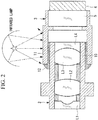
- the endoscopic image-acquisition unit configured as described above is assembled as follows. As shown in Fig. 2 , an adhesive 12 made of a thermosetting resin is applied to the outer surface of the fitting region 10 or the inner surface of the fitting region 11, the spacing between the objective-lens-unit frame 2 and the image-acquisition-device holding frame 3 is adjusted, and then the adhesive 12 is cured by heating it from the outside by using infrared rays. Although only one infrared lamp is shown in Fig. 2 for simplicity, in practice, multiple infrared lamps are disposed circumferentially for heating since it is necessary to heat the entire fitting region.
- the outer surface of the fitting region 11 is configured so that it is heated more easily by infrared irradiation compared with the region other than the fitting region 11. Therefore, it is possible to efficiently heat only the fitting region 11 by infrared irradiation of the fitting region 11. Accordingly, it is possible to suppress positional deviations due to thermal expansion of jigs and parts, which serves to suppress manufacturing errors, so that the accuracy of positioning between the objective lenses and the image-acquisition device can be improved.
- the image-acquisition-device holding frame 3, which is located on the outer side, is made of a metallic material, and the metallic material is plated with chromium.
- the metallic material is plated with chromium.
- other kinds of blackening treatment may be employed, such as chromate treatment, alumite treatment, or nickel plating. It is possible to employ treatment that enables black plating in relation to a metallic material that is used for the frame that is located on the outer side among the image-acquisition-device holding frame 3 and the objective-lens-unit frame 2.
- stainless steel is described as the metallic material, without limitation to stainless steel, other kinds of metallic material, such as copper, brass, aluminum, and iron, may be used.
- the objective-lens-unit frame 2 is located on the inner side and the image-acquisition-device holding frame 3 is located on the outer side when the objective-lens-unit frame 2 and the image-acquisition-device holding frame 3 are fitted together in this embodiment
- the configuration may be such that the objective-lens-unit frame 2 is located on the outer side and the image-acquisition-device holding frame 3 is located on the inner side.
- the outer surface of the fitting region 10 of the objective-lens-unit frame 2 which is located on the outer side when fitted, is chromium-plated or otherwise treated so that the infrared absorption rate will be higher.
- the outer surface of the fitting region 11 of the image-acquisition-device holding frame 3 is chromium-plated.
- an infrared-absorbing material may be applied to the outer surface of the fitting region 11.
- an infrared-absorbing material is applied to the outer surface of the fitting region of the frame that is located on the outer side when the objective-lens-unit frame and the image-acquisition-device holding frame are fitted together such that conditional expression (1) given earlier is satisfied.
- the outer surface of the fitting region is heated more easily by infrared irradiation compared with the outer surface of the region other than the fitting region.
- the infrared-absorbing material for example, a black paint, or a black paint in which a metal oxide, etc. is introduced so that infrared rays can be absorbed efficiently, may be used.
- black ink may be used alone, or powder of an oxide of a metal, such as chromium, copper, iron, nickel, or molybdenum, may be introduced to further improve the absorption rate, whereby the infrared absorption rate per unit area can be further improved.
- the infrared absorption rate of the fitting region can be made higher than that of the region other than the fitting region.
- the outer surface of the image-acquisition-device holding frame 3, located on the outer side when fitted, is configured such that the surface roughness of the outer surface of the fitting region 11 is greater than the surface roughness of the outer surface of the region other than the fitting region (the region labeled as "RA REGION" in the figure constitutes a rough surface).
- the outer surface of the image-acquisition-device holding frame 3 which is the frame that is located on the outer side when the objective-lens-unit frame 2 and the image-acquisition-device holding frame 3 are fitted together, is configured such that the outer surface of the fitting region 11 and the outer surface of the region other than the fitting region 11 satisfy conditional expression (1) given earlier and also satisfy conditional expression (3) given below: Ra > 3 ⁇ Rb where Ra signifies the maximum height of the surface roughness of the outer surface of the fitting region 11, and Rb signifies the maximum height of the surface roughness of the outer surface of the region other than the fitting region 11.
- the maximum height here refers to a value ( ⁇ m) indicating the difference between a maximum value and a minimum value of surface roughness. As shown in Fig. 4 , the maximum height represents the maximum value (Rmax in Fig. 4 ), in ⁇ m, of the difference between the maximum height and minimum height in the case where surface roughness is measured over a certain reference range L.
- the surface roughness of the outer surface of the fitting region 11 is made greater than the surface roughness of the outer surface of the region other than the fitting region 11, for example, by varying the rotation rate or moving amount of a cutting blade between the outer surface of the fitting region 11 and the outer surface of the region other than the fitting region 11 when machining the frame or by performing sandblasting after machining.
- blackening treatment such as plating, it is possible to configure an image-acquisition-device holding frame in which the outer surface of the fitting region 11 has a higher infrared absorption rate than the outer surface of the region other than the fitting region 11.
- the endoscopic image-acquisition unit configured as described above is assembled by applying an adhesive 12 made of a thermosetting resin to the outer surface of the fitting region 10 or the inner surface of the fitting region 11, adjusting the spacing between the objective-lens-unit frame 2 and the image-acquisition-device holding frame 3, and then curing the adhesive 12 by heating it from the outside by using infrared rays.
- the surface roughness of the outer surface of the fitting region 11 of the image-acquisition-device holding frame 3, which is located on the outer side when fitted with the objective-lens-unit frame 2, is greater than the surface roughness of the outer surface of the region other than the fitting region 11. Therefore, it is possible to efficiently heat only the fitting region 11 by infrared irradiation of the fitting region 11. Accordingly, it is possible to suppress positional deviations due to thermal expansion of jigs and parts, which serves to suppress manufacturing errors, so that the accuracy of positioning between the objective lenses and the image-acquisition device can be improved.
- the infrared absorption rate ⁇ of the outer surface of the image-acquisition-device holding frame 3, which is located on the outer side when fitted, is greater than the infrared absorption rate ⁇ of the outer surface of the region other than the fitting region 11 of the outer surface of the objective-lens-unit frame 2, which is located on the inner side when fitted.
- the outer surface of the fitting region 11 of the image-acquisition-device holding frame 3, having the infrared absorption rate p, is labeled as " ⁇ REGION”
- the outer surface of the region other than the fitting region 10 of the objective-lens-unit frame 2, having the infrared absorption rate ⁇ is labeled as " ⁇ REGION.”
- the outer surface of the frame that is located on the outer side when the objective-lens-unit frame 2 and the image-acquisition-device holding frame 3 are fitted together and the outer surface of the region other than the fitting region in the outer surface of the frame that is located on the inner side are configured to satisfy conditional expression (4) given below: ⁇ / ⁇ > 1.5 where ⁇ signifies the infrared absorption rate per unit area of the outer surface of the frame that is located on the outer side, and ⁇ signifies the infrared absorption rate per unit area of the outer surface of the region other than the fitting region in the outer surface of the frame that is located on the inner side.
- ⁇ here signifies the infrared absorption rate per unit area of the outer surface of the region other than the fitting region in the outer surface of the frame that is located on the inner side when fitted
- the entire outer surface of the frame that is located on the inner side when fitted, including the fitting region thereof may have the same infrared absorption rate ⁇ . This indicates that either is acceptable since the outer surface of the fitting region of the frame that is located on the inner side when fitted is not irradiated with infrared rays in the case of infrared irradiation from the outside.
- the image-acquisition-device holding frame 3, which is located on the outer side, and the objective-lens-unit frame 2, which is located on the inner side, are made of a metallic material.
- the configuration may be such that stainless steel is used as a metallic material for both frames, the peripheral surface of the region other than the fitting region of the objective-lens-unit frame 2, which is located on the inner side, is not plated or otherwise treated, so that the machined surface of the metallic material is exposed, constituting a lustrous metallic surface, and the outer surface of the fitting region of the image-acquisition-device holding frame 3, which is located on the outer side, is plated with chromium.
- the peripheral surface of the fitting region of the objective-lens-unit frame 2, which is located on the inner side, is not plated or otherwise treated, so that the machined surface of the metallic material is exposed, constituting a lustrous metallic surface, similarly to the peripheral surface of the region other than the fitting region.
- conditional expression (5) instead of conditional expression (4) given earlier, it is possible to further increase the infrared absorption rate in the fitting region.
- the image-acquisition-device holding frame 3 which is located on the outer side, is made of a metallic material, and the metallic material is plated with chromium.
- the metallic material is plated with chromium.
- other kinds of blackening treatment may be employed, such as chromate treatment, alumite treatment, or nickel plating.
- stainless steel is used for the image-acquisition-device holding frame 3
- other kinds of metallic material such as copper, brass, aluminum, and iron, may be used.
- the surface roughness of the outer surface of the image-acquisition-device holding frame 3, which is located on the outer side when fitted, is greater than the surface roughness of the outer surface of the region other than the fitting region 10 of the objective-lens-unit frame 2, which is located on the inner side.
- the outer surface of the image-acquisition-device holding frame 3, which is the frame that is located on the outer side when the objective-lens-unit frame 2 and the image-acquisition-device holding frame 3 are fitted together, and the outer surface of the region other than the fitting region 10 of the objective-lens-unit frame 2, which is the frame that is located on the inner side, are configured to satisfy conditional expression (4) given earlier and also satisfy conditional expression (6) given below: Rbo > 3 ⁇ Rai where Rai signifies the maximum height of the surface roughness of the outer surface of the region other than the fitting region in the outer surface of the frame that is located on the inner side, and Rbo signifies the maximum height of the surface roughness of the outer surface of the frame that is located on the outer side.
- the maximum height here refers to a value ( ⁇ m) indicating the difference between a maximum value and a minimum value of the height of surface roughness.
- Rai here signifies the maximum height of the surface roughness of the outer surface of the region other than the fitting region 10 in the outer surface of the frame that is located on the inner side
- the entire outer surface of the frame that is located on the inner side, including the fitting region thereof may have the same surface roughness Rai. This indicates that either is acceptable since the outer surface of the fitting region of the frame that is located on the inner side when fitted is not irradiated with infrared rays in the case of infrared irradiation from the outside.
- the objective-lens-unit frame 2 and the image-acquisition-device holding frame 3 are both made of a stainless steel material, and black plating is applied at least to the outer surfaces thereof.
- the surface roughness of the peripheral surface of the fitting region of the objective-lens-unit frame 2, which is located on the inner side in the fitting region may be either the same as or different from the surface roughness Rai of the peripheral surface of the region other than the fitting region.
- black plating of the metal it is possible to choose an appropriate treatment that enables blackening with a metallic material, such as chromium plating, chromate treatment, alumite treatment, or nickel plating.
- a metallic material such as chromium plating, chromate treatment, alumite treatment, or nickel plating.
- metallic materials such as copper, brass, aluminum, and iron, without limitation to stainless steel.
- Image-acquisition devices that use luminance signals are a type of image-acquisition device that uses such a reference quantity.
- Fig. 8 shows a list of application examples 1 to 15 of an optical system that requires positioning with such high precision that conditional expression (7) is satisfied. It is possible to improve the positioning precision by applying the above-described embodiments of the present invention to these application examples.
Landscapes
- Health & Medical Sciences (AREA)
- Life Sciences & Earth Sciences (AREA)
- Surgery (AREA)
- Physics & Mathematics (AREA)
- Engineering & Computer Science (AREA)
- Optics & Photonics (AREA)
- Animal Behavior & Ethology (AREA)
- Heart & Thoracic Surgery (AREA)
- Veterinary Medicine (AREA)
- Biophysics (AREA)
- Nuclear Medicine, Radiotherapy & Molecular Imaging (AREA)
- Pathology (AREA)
- Radiology & Medical Imaging (AREA)
- Public Health (AREA)
- Biomedical Technology (AREA)
- General Health & Medical Sciences (AREA)
- Medical Informatics (AREA)
- Molecular Biology (AREA)
- Astronomy & Astrophysics (AREA)
- General Physics & Mathematics (AREA)
- Multimedia (AREA)
- Manufacturing & Machinery (AREA)
- Endoscopes (AREA)
- Instruments For Viewing The Inside Of Hollow Bodies (AREA)
- Lens Barrels (AREA)
Applications Claiming Priority (2)
| Application Number | Priority Date | Filing Date | Title |
|---|---|---|---|
| JP2014068942 | 2014-03-28 | ||
| PCT/JP2015/052962 WO2015146290A1 (fr) | 2014-03-28 | 2015-02-03 | Unité d'imagerie pour endoscopes |
Publications (2)
| Publication Number | Publication Date |
|---|---|
| EP3123920A1 true EP3123920A1 (fr) | 2017-02-01 |
| EP3123920A4 EP3123920A4 (fr) | 2017-12-27 |
Family
ID=54194830
Family Applications (1)
| Application Number | Title | Priority Date | Filing Date |
|---|---|---|---|
| EP15768959.7A Withdrawn EP3123920A4 (fr) | 2014-03-28 | 2015-02-03 | Unité d'imagerie pour endoscopes |
Country Status (5)
| Country | Link |
|---|---|
| US (1) | US20160166132A1 (fr) |
| EP (1) | EP3123920A4 (fr) |
| JP (1) | JP5851668B1 (fr) |
| CN (1) | CN105473050B (fr) |
| WO (1) | WO2015146290A1 (fr) |
Families Citing this family (3)
| Publication number | Priority date | Publication date | Assignee | Title |
|---|---|---|---|---|
| JP2017185086A (ja) * | 2016-04-07 | 2017-10-12 | オリンパス株式会社 | 医療機器および医療機器用熱硬化型接着剤 |
| EP3599983B1 (fr) | 2017-03-24 | 2023-11-15 | Covidien LP | Endoscopes |
| JP6527646B2 (ja) * | 2017-05-26 | 2019-06-05 | オリンパス株式会社 | 光学ユニット |
Family Cites Families (12)
| Publication number | Priority date | Publication date | Assignee | Title |
|---|---|---|---|---|
| US5305736A (en) * | 1991-04-26 | 1994-04-26 | Asahi Kogaku Kogyo Kabushiki Kaisha | Distal end part of endoscope |
| JPH09192093A (ja) * | 1996-01-23 | 1997-07-29 | Olympus Optical Co Ltd | 撮像装置 |
| US6547721B1 (en) * | 1998-08-07 | 2003-04-15 | Olympus Optical Co., Ltd. | Endoscope capable of being autoclaved |
| JP3297033B2 (ja) * | 2000-02-02 | 2002-07-02 | オリンパス光学工業株式会社 | 内視鏡 |
| JP2002336190A (ja) * | 2001-03-12 | 2002-11-26 | Olympus Optical Co Ltd | 内視鏡 |
| US6936735B2 (en) * | 2002-08-27 | 2005-08-30 | Emd Chemicals, Inc. | Photostable cationic organic sunscreen compounds and compositions obtained therefrom |
| JP3967337B2 (ja) * | 2004-05-14 | 2007-08-29 | オリンパス株式会社 | 内視鏡および内視鏡装置 |
| JP4864624B2 (ja) * | 2006-09-28 | 2012-02-01 | Hoya株式会社 | 電子内視鏡の先端光学ユニット |
| JP2008125902A (ja) * | 2006-11-22 | 2008-06-05 | Pentax Corp | 内視鏡スコープおよび内視鏡スコープの製造方法 |
| JP2008018254A (ja) * | 2007-08-21 | 2008-01-31 | Olympus Corp | カプセル型内視鏡 |
| JP2010269072A (ja) * | 2009-05-25 | 2010-12-02 | Hoya Corp | 固体撮像装置及びその製造方法 |
| JP5189209B2 (ja) * | 2010-02-01 | 2013-04-24 | オリンパスメディカルシステムズ株式会社 | 内視鏡先端部構造 |
-
2015
- 2015-02-03 EP EP15768959.7A patent/EP3123920A4/fr not_active Withdrawn
- 2015-02-03 WO PCT/JP2015/052962 patent/WO2015146290A1/fr not_active Ceased
- 2015-02-03 CN CN201580001659.1A patent/CN105473050B/zh not_active Expired - Fee Related
- 2015-02-03 JP JP2015546762A patent/JP5851668B1/ja active Active
-
2016
- 2016-02-23 US US15/050,763 patent/US20160166132A1/en not_active Abandoned
Also Published As
| Publication number | Publication date |
|---|---|
| JPWO2015146290A1 (ja) | 2017-04-13 |
| CN105473050A (zh) | 2016-04-06 |
| JP5851668B1 (ja) | 2016-02-03 |
| EP3123920A4 (fr) | 2017-12-27 |
| CN105473050B (zh) | 2017-11-07 |
| WO2015146290A1 (fr) | 2015-10-01 |
| US20160166132A1 (en) | 2016-06-16 |
Similar Documents
| Publication | Publication Date | Title |
|---|---|---|
| EP3123920A1 (fr) | Unité d'imagerie pour endoscopes | |
| JP6994568B2 (ja) | 内視鏡および内視鏡の挿入部 | |
| US20160178884A1 (en) | Lenses unit for endoscope, and endoscope equipped with the same | |
| US10437039B2 (en) | Image-acquisition apparatus | |
| US20160161721A1 (en) | Lens assembly | |
| US20010033360A1 (en) | Hybrid lens and method for forming the same | |
| JP6006458B1 (ja) | 内視鏡用撮像ユニット | |
| EP3011891B1 (fr) | Unité de capture d'image endoscopique et dispositif endoscopique | |
| JP2014033730A5 (fr) | ||
| TWI507730B (zh) | The manufacturing method of optical box and optical module | |
| JP5958727B2 (ja) | 内視鏡 | |
| JP2015080646A (ja) | 内視鏡用レンズユニットおよびこれを備えた内視鏡 | |
| US20160302647A1 (en) | Endoscope imaging unit and method for assembling endoscope imaging unit | |
| JP2005062559A (ja) | 赤外線カメラ用レンズ | |
| EP2851727A1 (fr) | Ensemble optique d'objectif d'endoscope | |
| JP2016020951A (ja) | レンズ鏡筒および光学機器 | |
| JPWO2017217146A1 (ja) | 内視鏡用対物光学系 | |
| CN112946875B (zh) | 适用流动血液成像的红外内窥镜目镜光学系统 | |
| JP6226207B2 (ja) | 内視鏡 | |
| JP6774530B2 (ja) | レンズユニットおよびカメラモジュール | |
| TW200538779A (en) | Stucture and method for fixing a camera module | |
| CN222850809U (zh) | 红外显微镜物镜 | |
| TW201621374A (zh) | 透鏡組 | |
| US20060004259A1 (en) | Endoscope with relief of axial loading | |
| US20230309797A1 (en) | Endoscope and method of manufacturing a sealed unit of an endoscope |
Legal Events
| Date | Code | Title | Description |
|---|---|---|---|
| STAA | Information on the status of an ep patent application or granted ep patent |
Free format text: STATUS: THE INTERNATIONAL PUBLICATION HAS BEEN MADE |
|
| PUAI | Public reference made under article 153(3) epc to a published international application that has entered the european phase |
Free format text: ORIGINAL CODE: 0009012 |
|
| STAA | Information on the status of an ep patent application or granted ep patent |
Free format text: STATUS: REQUEST FOR EXAMINATION WAS MADE |
|
| 17P | Request for examination filed |
Effective date: 20161012 |
|
| AK | Designated contracting states |
Kind code of ref document: A1 Designated state(s): AL AT BE BG CH CY CZ DE DK EE ES FI FR GB GR HR HU IE IS IT LI LT LU LV MC MK MT NL NO PL PT RO RS SE SI SK SM TR |
|
| AX | Request for extension of the european patent |
Extension state: BA ME |
|
| DAX | Request for extension of the european patent (deleted) | ||
| A4 | Supplementary search report drawn up and despatched |
Effective date: 20171128 |
|
| RIC1 | Information provided on ipc code assigned before grant |
Ipc: G02B 23/24 20060101ALI20171122BHEP Ipc: A61B 1/00 20060101AFI20171122BHEP Ipc: A61B 1/04 20060101ALI20171122BHEP |
|
| STAA | Information on the status of an ep patent application or granted ep patent |
Free format text: STATUS: THE APPLICATION IS DEEMED TO BE WITHDRAWN |
|
| 18D | Application deemed to be withdrawn |
Effective date: 20180626 |