EP3124073B1 - Raccord médical - Google Patents
Raccord médical Download PDFInfo
- Publication number
- EP3124073B1 EP3124073B1 EP15770175.6A EP15770175A EP3124073B1 EP 3124073 B1 EP3124073 B1 EP 3124073B1 EP 15770175 A EP15770175 A EP 15770175A EP 3124073 B1 EP3124073 B1 EP 3124073B1
- Authority
- EP
- European Patent Office
- Prior art keywords
- section
- male connector
- valve element
- housing
- body section
- Prior art date
- Legal status (The legal status is an assumption and is not a legal conclusion. Google has not performed a legal analysis and makes no representation as to the accuracy of the status listed.)
- Active
Links
Images



Classifications
-
- A—HUMAN NECESSITIES
- A61—MEDICAL OR VETERINARY SCIENCE; HYGIENE
- A61M—DEVICES FOR INTRODUCING MEDIA INTO, OR ONTO, THE BODY; DEVICES FOR TRANSDUCING BODY MEDIA OR FOR TAKING MEDIA FROM THE BODY; DEVICES FOR PRODUCING OR ENDING SLEEP OR STUPOR
- A61M39/00—Tubes, tube connectors, tube couplings, valves, access sites or the like, specially adapted for medical use
- A61M39/22—Valves or arrangement of valves
- A61M39/26—Valves closing automatically on disconnecting the line and opening on reconnection thereof
-
- A—HUMAN NECESSITIES
- A61—MEDICAL OR VETERINARY SCIENCE; HYGIENE
- A61M—DEVICES FOR INTRODUCING MEDIA INTO, OR ONTO, THE BODY; DEVICES FOR TRANSDUCING BODY MEDIA OR FOR TAKING MEDIA FROM THE BODY; DEVICES FOR PRODUCING OR ENDING SLEEP OR STUPOR
- A61M39/00—Tubes, tube connectors, tube couplings, valves, access sites or the like, specially adapted for medical use
- A61M39/10—Tube connectors; Tube couplings
-
- A—HUMAN NECESSITIES
- A61—MEDICAL OR VETERINARY SCIENCE; HYGIENE
- A61M—DEVICES FOR INTRODUCING MEDIA INTO, OR ONTO, THE BODY; DEVICES FOR TRANSDUCING BODY MEDIA OR FOR TAKING MEDIA FROM THE BODY; DEVICES FOR PRODUCING OR ENDING SLEEP OR STUPOR
- A61M39/00—Tubes, tube connectors, tube couplings, valves, access sites or the like, specially adapted for medical use
- A61M39/10—Tube connectors; Tube couplings
- A61M39/1011—Locking means for securing connection; Additional tamper safeties
-
- A—HUMAN NECESSITIES
- A61—MEDICAL OR VETERINARY SCIENCE; HYGIENE
- A61M—DEVICES FOR INTRODUCING MEDIA INTO, OR ONTO, THE BODY; DEVICES FOR TRANSDUCING BODY MEDIA OR FOR TAKING MEDIA FROM THE BODY; DEVICES FOR PRODUCING OR ENDING SLEEP OR STUPOR
- A61M39/00—Tubes, tube connectors, tube couplings, valves, access sites or the like, specially adapted for medical use
- A61M39/22—Valves or arrangement of valves
- A61M39/24—Check- or non-return valves
-
- A—HUMAN NECESSITIES
- A61—MEDICAL OR VETERINARY SCIENCE; HYGIENE
- A61M—DEVICES FOR INTRODUCING MEDIA INTO, OR ONTO, THE BODY; DEVICES FOR TRANSDUCING BODY MEDIA OR FOR TAKING MEDIA FROM THE BODY; DEVICES FOR PRODUCING OR ENDING SLEEP OR STUPOR
- A61M39/00—Tubes, tube connectors, tube couplings, valves, access sites or the like, specially adapted for medical use
- A61M39/10—Tube connectors; Tube couplings
- A61M2039/1033—Swivel nut connectors, e.g. threaded connectors, bayonet-connectors
-
- A—HUMAN NECESSITIES
- A61—MEDICAL OR VETERINARY SCIENCE; HYGIENE
- A61M—DEVICES FOR INTRODUCING MEDIA INTO, OR ONTO, THE BODY; DEVICES FOR TRANSDUCING BODY MEDIA OR FOR TAKING MEDIA FROM THE BODY; DEVICES FOR PRODUCING OR ENDING SLEEP OR STUPOR
- A61M39/00—Tubes, tube connectors, tube couplings, valves, access sites or the like, specially adapted for medical use
- A61M39/22—Valves or arrangement of valves
- A61M39/24—Check- or non-return valves
- A61M2039/2433—Valve comprising a resilient or deformable element, e.g. flap valve, deformable disc
-
- A—HUMAN NECESSITIES
- A61—MEDICAL OR VETERINARY SCIENCE; HYGIENE
- A61M—DEVICES FOR INTRODUCING MEDIA INTO, OR ONTO, THE BODY; DEVICES FOR TRANSDUCING BODY MEDIA OR FOR TAKING MEDIA FROM THE BODY; DEVICES FOR PRODUCING OR ENDING SLEEP OR STUPOR
- A61M39/00—Tubes, tube connectors, tube couplings, valves, access sites or the like, specially adapted for medical use
- A61M39/22—Valves or arrangement of valves
- A61M39/26—Valves closing automatically on disconnecting the line and opening on reconnection thereof
- A61M2039/263—Valves closing automatically on disconnecting the line and opening on reconnection thereof where the fluid space within the valve is decreasing upon disconnection
-
- A—HUMAN NECESSITIES
- A61—MEDICAL OR VETERINARY SCIENCE; HYGIENE
- A61M—DEVICES FOR INTRODUCING MEDIA INTO, OR ONTO, THE BODY; DEVICES FOR TRANSDUCING BODY MEDIA OR FOR TAKING MEDIA FROM THE BODY; DEVICES FOR PRODUCING OR ENDING SLEEP OR STUPOR
- A61M39/00—Tubes, tube connectors, tube couplings, valves, access sites or the like, specially adapted for medical use
- A61M39/22—Valves or arrangement of valves
- A61M39/26—Valves closing automatically on disconnecting the line and opening on reconnection thereof
- A61M2039/266—Valves closing automatically on disconnecting the line and opening on reconnection thereof where the valve comprises venting channels, e.g. to insure better connection, to help decreasing the fluid space upon disconnection, or to help the fluid space to remain the same during disconnection
Definitions
- Patent Literature 1 As a medical connector which is used in, for example, various medical apparatuses, infusion containers, and liquid feeding instruments and which connects tube bodies of a medical instrument, for example, a medical connector as described in Patent Literature 1 is known.
- a valve element having a head section and a body section is housed in a housing of the medical connector.
- the body section of the valve element has a hollow section.
- An air passage that connects the hollow section of the body section with the outside of the housing is formed in the housing.
- Patent Literature 1 JP 2013-500128 A
- the body section of the valve element has a bellows-shaped circumferential wall that forms the hollow section, and on a bottom surface of the receiving recess section of the housing, a support protrusion is formed which comes into contact with an end surface of the hollow section facing the head section when the bellows-shaped circumferential wall is folded when the male connector is connected and suppresses further deformation of the bellows-shaped circumferential wall.
- a seal protrusion that is liquid-tightly and slidably attached to the receiving recess section of the housing is provided around an outer circumferential surface of the body section of the valve element at an end section of the bellows-shaped circumferential wall facing the head section.
- the male connector contracts the body section of the valve element when the male connector pushes the head section of the valve element.
- the male connector is removed along with disconnection of the male connector from the male connector connection section, it is possible to expand and restore the body section of the valve element. Therefore, it is possible to suppress or prevent the increase of volume of the fluid flow passage in the housing, which has been concerned to occur when the male connector is removed, by expansion of the body section of the valve element, so that it is possible to suppress or prevent occurrence of drawing-in of the fluid at the medical instrument connection section when the male connector is removed.
- a medical connector that can suppress or prevent occurrence of drawing-in of fluid at the medical instrument connection section when removing the male connector from the male connector connection section and suppress or prevent occurrence of contamination due to adhesion of fluid at the body section of the valve element.
- the vertical direction means a direction along an axis line of a medical connector
- an upper side means a side on which a male connector connection section is arranged (in other words, an upper side in Fig. 1 )
- a lower side means a side on which a medical instrument connection section is arranged (in other words, a lower side in Fig. 1 ) .
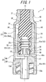
- a medical connector 1 includes a housing 20 and a valve element 30.
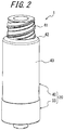
- the housing 20 includes a cap 40 and a holder 50 and is formed by fixing the cap 40 to the holder 50.
- the cap 40 has a cylindrical male connector connection section 41 at its upper end. On an outer circumference surface of the male connector connection section 41, in this example, a triple threaded screw to connect a lure lock type male connector is formed. The triple threaded screw can be omitted.
- a cylindrical outer circumferential wall section 43 is vertically formed at a lower end of the male connector connection section 41 through a taper wall section 42 whose diameter increases in taper form.
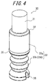
- the valve element 30 has a column-shaped head section 31 that closes the male connector connection section 41.
- a column-shaped body section 33 is provided in a coupled manner to the lower end of the head section 31 through a shoulder section 32 whose diameter increases in taper form in the same angle as that of the taper wall section 42 of the cap 40.
- An upper part 33a of the body section 33 is formed into a solid shape and a lower part 33b of the body section 33 is formed into a hollow shape.
- the body section 33 has a hollow section 33c that opens at an end section opposite to the head section 31.
- a notch 34 having a V-shaped cross-sectional shape is formed near the upper end of the outer circumferential surface of the upper part 33a of the body section 33.
- a seal protrusion 35 that is liquid-tightly and slidably attached to a receiving recess section 51 described later is provided around the lower end of the outer circumferential surface of the upper part 33a of the body section 33.
- a first half circumferential part 52a around the axis line O is inserted inside the outer circumferential wall section 43 of the cap 40, the outer circumferential surface of the half circumferential part 52a is in liquid-tightly contact with the inner circumferential surface of the outer circumferential wall section 43 of the cap 40, and the upper surface of the half circumferential part 52a is in liquid-tightly contact with the lower surface of the taper wall section 42 of the cap 40.
- the remaining half circumferential part around the axis line O of the inner circumferential wall section 52 that is, a second half circumferential part 52b, is smaller than the first half circumferential part 52a in diameter.
- the size of the inner diameter of the second half circumferential part 52b is the same as that of the first half circumferential part 52a.
- the upper end of the second half circumferential part 52b is located lower than the upper end of the first half circumferential part 52a.
- a medical instrument connection section 55 is provided under the recess section bottom wall 53.
- the medical instrument connection section 55 is formed as a lure lock type male connector in which a cylindrical body 55a extends along the axis line O.
- the medical connector 1 is formed as a mixed injection plug having one male connector as the medical instrument connection section 55.
- the medical connector 1 can be formed as, for example, a T-type mixed injection port having a further connection section and a three-way cock instead of the above.
- a half-disk-shaped notch 53a positioned below the second half circumferential part 52b of the inner circumferential wall section 52 is formed below the recess section bottom wall 53 and a fluid connection passage 56 formed outside the receiving recess section 51 and a fluid flow passage 55b in the medical instrument connection section 55 are connected to each other by the notch 53a.
- the cap 40 and the holder 50 are fixed to each other by, for example, welding or bonding.
- the cap 40 and the holder 50 may be fixed by using, for example, heat welding.
- the housing 20 is formed by two members, which are the cap 40 and the holder 50.
- the housing 20 may be formed by one member or three members according to a manufacturing method to be employed.
- a material of the valve element 30 it is preferable to use, for example, a rubber material and a thermoplastic elastomer.
- a rotation preventing means (the protrusion 54 and the recess section 36) that prevents rotation of the body section 33 in a circumferential direction is provided between the body section 33 of the valve element 30 and the receiving recess section 51 of the housing 20, so that it is possible to consistently maintain a certain direction in which the head section 31 of the valve element 30 is tilted. Therefore, it is possible to consistently maintain a certain track in which the fluid in the medical connector 1 flows. Further, by the rotation preventing means, it is possible to position the notch 34 at the center of the second half circumferential part 52b in the circumferential direction, so that it is possible to guide the fluid from inside of the male connector C to the fluid connection passage 56 by a shortest track at all times .
- the body section 33 of the valve element 30 has the bellows-shaped circumferential wall 33d and the bellows-shaped circumferential wall 33d contracts when the male connector C is connected.
- the notch 34 is provided to the valve element 30.
- any configuration can be employed as long as the fluid flow passage R in the male connector C can be connected to the fluid flow passage 55b in the medical instrument connection section 55 through the fluid connection passage 56 when the male connector C is connected to the male connector connection section 41.
- the notch 34 is not provided, for example, it is possible to employ a configuration in which the upper surface of the head section 31 of the valve element 30 has a sloped shape and a configuration in which a groove opened to the outer circumferential surface of the head section 31 is formed in the upper surface of the head section 31.
- the position where the notch 34 is provided is not limited as long as the fluid flow passage R in the male connector C can be connected to the fluid flow passage 55b in the medical instrument connection section 55 through the fluid connection passage 56 by tilting the head section 31 when the male connector C is connected.
- the notch 34 is not necessarily required to be provided near the upper end of the outer circumferential surface of the upper part 33a of the body section 33 as described above, but can be provided at any position above the seal protrusion 35.
- the notch 34 can be provided in the outer circumferential surface of the head section 31.
Landscapes
- Health & Medical Sciences (AREA)
- Heart & Thoracic Surgery (AREA)
- Pulmonology (AREA)
- Engineering & Computer Science (AREA)
- Anesthesiology (AREA)
- Biomedical Technology (AREA)
- Hematology (AREA)
- Life Sciences & Earth Sciences (AREA)
- Animal Behavior & Ethology (AREA)
- General Health & Medical Sciences (AREA)
- Public Health (AREA)
- Veterinary Medicine (AREA)
- Infusion, Injection, And Reservoir Apparatuses (AREA)
Claims (4)
- Raccord médical (1) comprenant :un boîtier (20) comprenant une section de connexion de connecteur mâle (41) et une section de connexion d'instrument médical (55) ; etun élément de soupape (30) comprenant une section de tête (31) qui ferme la section de connexion de connecteur mâle (41) et une section de corps (33) qui est reliée à la section de tête (31),où la section de corps (33) de l'élément de soupape (30) est disposée dans une section d'évidement de réception (51) formée dans le boîtier (20), eten reliant un connecteur mâle (C) à la section de connexion de connecteur mâle (41), la section de tête (31) de l'élément de soupape (30) est poussée par le connecteur mâle (C) pendant que la section de tête (31) contracte la section de corps (33), un passage d'écoulement de fluide (R) formé dans le connecteur mâle (C) est relié à un passage d'écoulement de fluide (55b) formé dans la section de connexion d'instrument médical (55) à travers un passage de connexion de fluide (56) formé à l'extérieur de la section d'évidement de réception (51), et la section de corps (33) est couverte par la section d'évidement de réception (51),caractérisé en ce quela section de corps (33) de l'élément de soupape (30) comprend une section creuse (33c) qui s'ouvre au niveau d'une section d'extrémité opposée à la section de tête (31), et la section de corps (33) de l'élément de soupape (30) comprend une paroi circonférentielle en forme de soufflet (33d) qui forme la section creuse (33c), et sur une surface inférieure de la section d'évidement de réception (51) du boîtier (20), est formée une saillie de support (58) qui vient en contact avec une surface d'extrémité de la section creuse (33c) tournée vers la section de tête (31) lorsque la paroi circonférentielle en forme de soufflet (33d) est repliée quand le connecteur mâle (C) est relié et supprime une déformation supplémentaire de la paroi circonférentielle en forme de soufflet (33d).
- Raccord médical (1) selon la revendication 1, dans lequel
sur une surface circonférentielle extérieure de l'élément de soupape (30), est formée une encoche (34) qui relie le passage d'écoulement de fluide (R) du connecteur mâle (C) au passage d'écoulement de fluide (55d) de la section de connexion d'instrument médical (55) à travers le passage de connexion de fluide (56) en inclinant la section de tête (31) lorsque le connecteur mâle (C) est connecté, et
un moyen de prévention de rotation (36) qui empêche la rotation de la section de corps (33) dans une direction circonférentielle est prévu entre la section de corps (33) de l'élément de soupape (30) et la section d'évidement de réception (51) du boîtier (20). - Raccord médical (1) selon la revendication 1 ou 2, dans lequel
le boîtier (20) comprend un passage d'air (57) qui relie l'extérieur du boîtier (20) à la section creuse (33c) de l'élément de soupape (30). - Raccord médical (1) selon la revendication 3, dans lequel
une saillie d'étanchéité (35) qui est fixée de façon étanche au liquide et de façon coulissante à la section d'évidement de réception (51) du boîtier (20) est prévue autour d'une surface circonférentielle extérieure de la section de corps (33) de l'élément de soupape (30) au niveau d'une section d'extrémité de la paroi circonférentielle en forme de soufflet (33d) tournée vers la section de tête (31).
Applications Claiming Priority (2)
| Application Number | Priority Date | Filing Date | Title |
|---|---|---|---|
| JP2014069206 | 2014-03-28 | ||
| PCT/JP2015/001123 WO2015145998A1 (fr) | 2014-03-28 | 2015-03-03 | Raccord médical |
Publications (3)
| Publication Number | Publication Date |
|---|---|
| EP3124073A1 EP3124073A1 (fr) | 2017-02-01 |
| EP3124073A4 EP3124073A4 (fr) | 2017-09-27 |
| EP3124073B1 true EP3124073B1 (fr) | 2019-01-30 |
Family
ID=54194553
Family Applications (1)
| Application Number | Title | Priority Date | Filing Date |
|---|---|---|---|
| EP15770175.6A Active EP3124073B1 (fr) | 2014-03-28 | 2015-03-03 | Raccord médical |
Country Status (5)
| Country | Link |
|---|---|
| US (1) | US20170014618A1 (fr) |
| EP (1) | EP3124073B1 (fr) |
| JP (1) | JP6403757B2 (fr) |
| CN (1) | CN106132474B (fr) |
| WO (1) | WO2015145998A1 (fr) |
Families Citing this family (11)
| Publication number | Priority date | Publication date | Assignee | Title |
|---|---|---|---|---|
| EP3199200B1 (fr) * | 2014-09-24 | 2024-09-11 | Terumo Kabushiki Kaisha | Raccord medical |
| WO2016157829A1 (fr) * | 2015-03-27 | 2016-10-06 | テルモ株式会社 | Connecteur médical |
| WO2016157886A1 (fr) * | 2015-03-30 | 2016-10-06 | テルモ株式会社 | Raccord médical |
| JP6865220B2 (ja) | 2016-06-24 | 2021-04-28 | テルモ株式会社 | コネクタ |
| JP6945641B2 (ja) * | 2017-05-19 | 2021-10-06 | エーディーヴィーケア メディカル インコーポレイテッド | 密閉システム調剤投薬装置 |
| US10946167B2 (en) | 2018-06-14 | 2021-03-16 | Covidien Lp | Catheter hub and strain relief |
| GB2578169A (en) * | 2018-10-19 | 2020-04-22 | Conceptomed As | Fluid transfer devices |
| DE102019204211A1 (de) * | 2019-03-27 | 2020-10-01 | B. Braun Melsungen Aktiengesellschaft | Medizinischer Fluidkonnektor |
| US11779750B2 (en) | 2020-09-29 | 2023-10-10 | Carefusion 303, Inc. | Needleless connector with valve pivot support |
| JP7766042B2 (ja) | 2020-11-12 | 2025-11-07 | テルモ株式会社 | 医療用コネクタ |
| US12268837B2 (en) * | 2022-12-28 | 2025-04-08 | Carefusion 303, Inc. | Neutral displacement connector |
Family Cites Families (20)
| Publication number | Priority date | Publication date | Assignee | Title |
|---|---|---|---|---|
| US5242393A (en) * | 1992-06-18 | 1993-09-07 | Becton, Dickinson And Company | Valved blunt cannula injection site |
| US5782816A (en) * | 1995-09-07 | 1998-07-21 | David R. Kipp | Bi-directional valve and method of using same |
| US5738663A (en) * | 1995-12-15 | 1998-04-14 | Icu Medical, Inc. | Medical valve with fluid escape space |
| US5788215A (en) * | 1995-12-29 | 1998-08-04 | Rymed Technologies | Medical intravenous administration line connectors having a luer or pressure activated valve |
| US5730418A (en) * | 1996-09-30 | 1998-03-24 | The Kipp Group | Minimum fluid displacement medical connector |
| US6228069B1 (en) * | 1999-04-05 | 2001-05-08 | Filtertek Inc. | Needleless access device |
| US7837658B2 (en) * | 2001-11-13 | 2010-11-23 | Nypro Inc. | Anti-drawback medical valve |
| US7914502B2 (en) * | 2003-07-31 | 2011-03-29 | Nypro Inc. | Anti-drawback medical valve |
| US7600530B2 (en) * | 2004-08-09 | 2009-10-13 | Medegen, Inc. | Connector with check valve and method of use |
| AU2006247269B2 (en) * | 2005-05-16 | 2011-11-10 | Nypro Inc. | Anti-drawback medical valve |
| US8511638B2 (en) * | 2008-09-05 | 2013-08-20 | Carefusion 303, Inc. | Neonatal Luer-activated medical connector |
| JP2010246829A (ja) * | 2009-04-20 | 2010-11-04 | Terumo Corp | コネクタ |
| US8715247B2 (en) * | 2009-07-30 | 2014-05-06 | Carefusion 303, Inc. | Collapsible valve |
| JP2012005605A (ja) * | 2010-06-23 | 2012-01-12 | Top Corp | コネクタ |
| JP3166779U (ja) * | 2011-01-07 | 2011-03-24 | 秀鳳 潘 | ボールバルブを備えたシリンジアダプタ |
| US9375561B2 (en) * | 2011-09-02 | 2016-06-28 | Carefusion 303, Inc. | Self-flushing valve |
| JP5241045B2 (ja) * | 2011-09-12 | 2013-07-17 | 信越ポリマー株式会社 | コネクタ用弁体及びコネクタ |
| JP6102747B2 (ja) * | 2011-12-27 | 2017-03-29 | ニプロ株式会社 | ニードルレスコネクター |
| CN202982812U (zh) * | 2012-12-03 | 2013-06-12 | 太平洋医材股份有限公司 | 免针式接头结构 |
| TWM474527U (zh) * | 2013-12-11 | 2014-03-21 | Lily Medical Corp | 免針連接頭模組 |
-
2015
- 2015-03-03 WO PCT/JP2015/001123 patent/WO2015145998A1/fr not_active Ceased
- 2015-03-03 JP JP2016509966A patent/JP6403757B2/ja active Active
- 2015-03-03 CN CN201580017313.0A patent/CN106132474B/zh active Active
- 2015-03-03 EP EP15770175.6A patent/EP3124073B1/fr active Active
-
2016
- 2016-09-27 US US15/277,676 patent/US20170014618A1/en not_active Abandoned
Non-Patent Citations (1)
| Title |
|---|
| None * |
Also Published As
| Publication number | Publication date |
|---|---|
| EP3124073A4 (fr) | 2017-09-27 |
| WO2015145998A1 (fr) | 2015-10-01 |
| CN106132474B (zh) | 2020-06-16 |
| EP3124073A1 (fr) | 2017-02-01 |
| CN106132474A (zh) | 2016-11-16 |
| US20170014618A1 (en) | 2017-01-19 |
| JPWO2015145998A1 (ja) | 2017-04-13 |
| JP6403757B2 (ja) | 2018-10-10 |
Similar Documents
| Publication | Publication Date | Title |
|---|---|---|
| EP3124073B1 (fr) | Raccord médical | |
| EP3199200B1 (fr) | Raccord medical | |
| CN103124582B (zh) | 具有可关闭的鲁尔连接器的医用连接器 | |
| EP3383478B1 (fr) | Capuchon flexible pour connecteurs coniques | |
| CN102089030B (zh) | 具有通用端部构件的注射器 | |
| US20190321265A1 (en) | System, apparatus and method employed with enteral systems | |
| JP6776225B2 (ja) | 医療用コネクタ | |
| US20180021560A1 (en) | Medical connector | |
| US10232162B2 (en) | Connector | |
| CN104254361A (zh) | 导管适配器孔阀 | |
| CA2943581C (fr) | Dispositif de melange et/ou de transfert | |
| JP2012512726A (ja) | 閉鎖可能なルアーコネクタを備える医療用コネクタ | |
| JP3203662U (ja) | コネクタ | |
| JP2018515266A (ja) | 医療用液体を導く接続アセンブリ | |
| KR20160010112A (ko) | 약병 교체 방지 기능을 구비한 안전 접속구 및 이 접속구를 포함하는 수액 제품 | |
| JP6521989B2 (ja) | 使い捨て医療用品を無菌接続する装置 | |
| KR20170045609A (ko) | 의료용 수액세트의 접속구 | |
| RU2850559C1 (ru) | Универсальный штуцер для контейнера для текучей среды | |
| RU2432189C1 (ru) | Контейнер для крови и ее компонентов | |
| HK1230997A1 (en) | Catheter devices with valves and related methods |
Legal Events
| Date | Code | Title | Description |
|---|---|---|---|
| STAA | Information on the status of an ep patent application or granted ep patent |
Free format text: STATUS: THE INTERNATIONAL PUBLICATION HAS BEEN MADE |
|
| PUAI | Public reference made under article 153(3) epc to a published international application that has entered the european phase |
Free format text: ORIGINAL CODE: 0009012 |
|
| STAA | Information on the status of an ep patent application or granted ep patent |
Free format text: STATUS: REQUEST FOR EXAMINATION WAS MADE |
|
| 17P | Request for examination filed |
Effective date: 20161025 |
|
| AK | Designated contracting states |
Kind code of ref document: A1 Designated state(s): AL AT BE BG CH CY CZ DE DK EE ES FI FR GB GR HR HU IE IS IT LI LT LU LV MC MK MT NL NO PL PT RO RS SE SI SK SM TR |
|
| AX | Request for extension of the european patent |
Extension state: BA ME |
|
| DAV | Request for validation of the european patent (deleted) | ||
| DAX | Request for extension of the european patent (deleted) | ||
| A4 | Supplementary search report drawn up and despatched |
Effective date: 20170830 |
|
| RIC1 | Information provided on ipc code assigned before grant |
Ipc: A61M 39/26 20060101AFI20170824BHEP |
|
| GRAP | Despatch of communication of intention to grant a patent |
Free format text: ORIGINAL CODE: EPIDOSNIGR1 |
|
| STAA | Information on the status of an ep patent application or granted ep patent |
Free format text: STATUS: GRANT OF PATENT IS INTENDED |
|
| INTG | Intention to grant announced |
Effective date: 20180731 |
|
| GRAS | Grant fee paid |
Free format text: ORIGINAL CODE: EPIDOSNIGR3 |
|
| GRAA | (expected) grant |
Free format text: ORIGINAL CODE: 0009210 |
|
| STAA | Information on the status of an ep patent application or granted ep patent |
Free format text: STATUS: THE PATENT HAS BEEN GRANTED |
|
| AK | Designated contracting states |
Kind code of ref document: B1 Designated state(s): AL AT BE BG CH CY CZ DE DK EE ES FI FR GB GR HR HU IE IS IT LI LT LU LV MC MK MT NL NO PL PT RO RS SE SI SK SM TR |
|
| REG | Reference to a national code |
Ref country code: GB Ref legal event code: FG4D |
|
| REG | Reference to a national code |
Ref country code: CH Ref legal event code: EP |
|
| REG | Reference to a national code |
Ref country code: AT Ref legal event code: REF Ref document number: 1092757 Country of ref document: AT Kind code of ref document: T Effective date: 20190215 |
|
| REG | Reference to a national code |
Ref country code: IE Ref legal event code: FG4D |
|
| REG | Reference to a national code |
Ref country code: DE Ref legal event code: R096 Ref document number: 602015024078 Country of ref document: DE |
|
| REG | Reference to a national code |
Ref country code: LT Ref legal event code: MG4D |
|
| REG | Reference to a national code |
Ref country code: NL Ref legal event code: MP Effective date: 20190130 |
|
| PG25 | Lapsed in a contracting state [announced via postgrant information from national office to epo] |
Ref country code: NO Free format text: LAPSE BECAUSE OF FAILURE TO SUBMIT A TRANSLATION OF THE DESCRIPTION OR TO PAY THE FEE WITHIN THE PRESCRIBED TIME-LIMIT Effective date: 20190430 Ref country code: PT Free format text: LAPSE BECAUSE OF FAILURE TO SUBMIT A TRANSLATION OF THE DESCRIPTION OR TO PAY THE FEE WITHIN THE PRESCRIBED TIME-LIMIT Effective date: 20190530 Ref country code: ES Free format text: LAPSE BECAUSE OF FAILURE TO SUBMIT A TRANSLATION OF THE DESCRIPTION OR TO PAY THE FEE WITHIN THE PRESCRIBED TIME-LIMIT Effective date: 20190130 Ref country code: PL Free format text: LAPSE BECAUSE OF FAILURE TO SUBMIT A TRANSLATION OF THE DESCRIPTION OR TO PAY THE FEE WITHIN THE PRESCRIBED TIME-LIMIT Effective date: 20190130 Ref country code: NL Free format text: LAPSE BECAUSE OF FAILURE TO SUBMIT A TRANSLATION OF THE DESCRIPTION OR TO PAY THE FEE WITHIN THE PRESCRIBED TIME-LIMIT Effective date: 20190130 Ref country code: LT Free format text: LAPSE BECAUSE OF FAILURE TO SUBMIT A TRANSLATION OF THE DESCRIPTION OR TO PAY THE FEE WITHIN THE PRESCRIBED TIME-LIMIT Effective date: 20190130 Ref country code: SE Free format text: LAPSE BECAUSE OF FAILURE TO SUBMIT A TRANSLATION OF THE DESCRIPTION OR TO PAY THE FEE WITHIN THE PRESCRIBED TIME-LIMIT Effective date: 20190130 Ref country code: FI Free format text: LAPSE BECAUSE OF FAILURE TO SUBMIT A TRANSLATION OF THE DESCRIPTION OR TO PAY THE FEE WITHIN THE PRESCRIBED TIME-LIMIT Effective date: 20190130 |
|
| REG | Reference to a national code |
Ref country code: AT Ref legal event code: MK05 Ref document number: 1092757 Country of ref document: AT Kind code of ref document: T Effective date: 20190130 |
|
| PG25 | Lapsed in a contracting state [announced via postgrant information from national office to epo] |
Ref country code: HR Free format text: LAPSE BECAUSE OF FAILURE TO SUBMIT A TRANSLATION OF THE DESCRIPTION OR TO PAY THE FEE WITHIN THE PRESCRIBED TIME-LIMIT Effective date: 20190130 Ref country code: RS Free format text: LAPSE BECAUSE OF FAILURE TO SUBMIT A TRANSLATION OF THE DESCRIPTION OR TO PAY THE FEE WITHIN THE PRESCRIBED TIME-LIMIT Effective date: 20190130 Ref country code: BG Free format text: LAPSE BECAUSE OF FAILURE TO SUBMIT A TRANSLATION OF THE DESCRIPTION OR TO PAY THE FEE WITHIN THE PRESCRIBED TIME-LIMIT Effective date: 20190430 Ref country code: IS Free format text: LAPSE BECAUSE OF FAILURE TO SUBMIT A TRANSLATION OF THE DESCRIPTION OR TO PAY THE FEE WITHIN THE PRESCRIBED TIME-LIMIT Effective date: 20190530 Ref country code: GR Free format text: LAPSE BECAUSE OF FAILURE TO SUBMIT A TRANSLATION OF THE DESCRIPTION OR TO PAY THE FEE WITHIN THE PRESCRIBED TIME-LIMIT Effective date: 20190501 Ref country code: LV Free format text: LAPSE BECAUSE OF FAILURE TO SUBMIT A TRANSLATION OF THE DESCRIPTION OR TO PAY THE FEE WITHIN THE PRESCRIBED TIME-LIMIT Effective date: 20190130 |
|
| PG25 | Lapsed in a contracting state [announced via postgrant information from national office to epo] |
Ref country code: EE Free format text: LAPSE BECAUSE OF FAILURE TO SUBMIT A TRANSLATION OF THE DESCRIPTION OR TO PAY THE FEE WITHIN THE PRESCRIBED TIME-LIMIT Effective date: 20190130 Ref country code: SK Free format text: LAPSE BECAUSE OF FAILURE TO SUBMIT A TRANSLATION OF THE DESCRIPTION OR TO PAY THE FEE WITHIN THE PRESCRIBED TIME-LIMIT Effective date: 20190130 Ref country code: DK Free format text: LAPSE BECAUSE OF FAILURE TO SUBMIT A TRANSLATION OF THE DESCRIPTION OR TO PAY THE FEE WITHIN THE PRESCRIBED TIME-LIMIT Effective date: 20190130 Ref country code: MC Free format text: LAPSE BECAUSE OF FAILURE TO SUBMIT A TRANSLATION OF THE DESCRIPTION OR TO PAY THE FEE WITHIN THE PRESCRIBED TIME-LIMIT Effective date: 20190130 Ref country code: AL Free format text: LAPSE BECAUSE OF FAILURE TO SUBMIT A TRANSLATION OF THE DESCRIPTION OR TO PAY THE FEE WITHIN THE PRESCRIBED TIME-LIMIT Effective date: 20190130 Ref country code: IT Free format text: LAPSE BECAUSE OF FAILURE TO SUBMIT A TRANSLATION OF THE DESCRIPTION OR TO PAY THE FEE WITHIN THE PRESCRIBED TIME-LIMIT Effective date: 20190130 Ref country code: RO Free format text: LAPSE BECAUSE OF FAILURE TO SUBMIT A TRANSLATION OF THE DESCRIPTION OR TO PAY THE FEE WITHIN THE PRESCRIBED TIME-LIMIT Effective date: 20190130 Ref country code: CZ Free format text: LAPSE BECAUSE OF FAILURE TO SUBMIT A TRANSLATION OF THE DESCRIPTION OR TO PAY THE FEE WITHIN THE PRESCRIBED TIME-LIMIT Effective date: 20190130 |
|
| REG | Reference to a national code |
Ref country code: CH Ref legal event code: PL Ref country code: DE Ref legal event code: R097 Ref document number: 602015024078 Country of ref document: DE |
|
| PG25 | Lapsed in a contracting state [announced via postgrant information from national office to epo] |
Ref country code: SM Free format text: LAPSE BECAUSE OF FAILURE TO SUBMIT A TRANSLATION OF THE DESCRIPTION OR TO PAY THE FEE WITHIN THE PRESCRIBED TIME-LIMIT Effective date: 20190130 Ref country code: LU Free format text: LAPSE BECAUSE OF NON-PAYMENT OF DUE FEES Effective date: 20190303 |
|
| REG | Reference to a national code |
Ref country code: BE Ref legal event code: MM Effective date: 20190331 |
|
| PLBE | No opposition filed within time limit |
Free format text: ORIGINAL CODE: 0009261 |
|
| STAA | Information on the status of an ep patent application or granted ep patent |
Free format text: STATUS: NO OPPOSITION FILED WITHIN TIME LIMIT |
|
| PG25 | Lapsed in a contracting state [announced via postgrant information from national office to epo] |
Ref country code: AT Free format text: LAPSE BECAUSE OF FAILURE TO SUBMIT A TRANSLATION OF THE DESCRIPTION OR TO PAY THE FEE WITHIN THE PRESCRIBED TIME-LIMIT Effective date: 20190130 |
|
| 26N | No opposition filed |
Effective date: 20191031 |
|
| PG25 | Lapsed in a contracting state [announced via postgrant information from national office to epo] |
Ref country code: IE Free format text: LAPSE BECAUSE OF NON-PAYMENT OF DUE FEES Effective date: 20190303 Ref country code: LI Free format text: LAPSE BECAUSE OF NON-PAYMENT OF DUE FEES Effective date: 20190331 Ref country code: CH Free format text: LAPSE BECAUSE OF NON-PAYMENT OF DUE FEES Effective date: 20190331 |
|
| PG25 | Lapsed in a contracting state [announced via postgrant information from national office to epo] |
Ref country code: BE Free format text: LAPSE BECAUSE OF NON-PAYMENT OF DUE FEES Effective date: 20190331 Ref country code: SI Free format text: LAPSE BECAUSE OF FAILURE TO SUBMIT A TRANSLATION OF THE DESCRIPTION OR TO PAY THE FEE WITHIN THE PRESCRIBED TIME-LIMIT Effective date: 20190130 |
|
| PG25 | Lapsed in a contracting state [announced via postgrant information from national office to epo] |
Ref country code: TR Free format text: LAPSE BECAUSE OF FAILURE TO SUBMIT A TRANSLATION OF THE DESCRIPTION OR TO PAY THE FEE WITHIN THE PRESCRIBED TIME-LIMIT Effective date: 20190130 |
|
| PG25 | Lapsed in a contracting state [announced via postgrant information from national office to epo] |
Ref country code: MT Free format text: LAPSE BECAUSE OF NON-PAYMENT OF DUE FEES Effective date: 20190303 |
|
| PG25 | Lapsed in a contracting state [announced via postgrant information from national office to epo] |
Ref country code: CY Free format text: LAPSE BECAUSE OF FAILURE TO SUBMIT A TRANSLATION OF THE DESCRIPTION OR TO PAY THE FEE WITHIN THE PRESCRIBED TIME-LIMIT Effective date: 20190130 |
|
| PG25 | Lapsed in a contracting state [announced via postgrant information from national office to epo] |
Ref country code: HU Free format text: LAPSE BECAUSE OF FAILURE TO SUBMIT A TRANSLATION OF THE DESCRIPTION OR TO PAY THE FEE WITHIN THE PRESCRIBED TIME-LIMIT; INVALID AB INITIO Effective date: 20150303 |
|
| PG25 | Lapsed in a contracting state [announced via postgrant information from national office to epo] |
Ref country code: MK Free format text: LAPSE BECAUSE OF FAILURE TO SUBMIT A TRANSLATION OF THE DESCRIPTION OR TO PAY THE FEE WITHIN THE PRESCRIBED TIME-LIMIT Effective date: 20190130 |
|
| PGFP | Annual fee paid to national office [announced via postgrant information from national office to epo] |
Ref country code: GB Payment date: 20260202 Year of fee payment: 12 |
|
| PGFP | Annual fee paid to national office [announced via postgrant information from national office to epo] |
Ref country code: DE Payment date: 20260128 Year of fee payment: 12 |
|
| PGFP | Annual fee paid to national office [announced via postgrant information from national office to epo] |
Ref country code: FR Payment date: 20260209 Year of fee payment: 12 |