EP3124127A1 - Hochdruckreinigungsgerät für die kleinteilreinigung - Google Patents
Hochdruckreinigungsgerät für die kleinteilreinigung Download PDFInfo
- Publication number
- EP3124127A1 EP3124127A1 EP16181045.2A EP16181045A EP3124127A1 EP 3124127 A1 EP3124127 A1 EP 3124127A1 EP 16181045 A EP16181045 A EP 16181045A EP 3124127 A1 EP3124127 A1 EP 3124127A1
- Authority
- EP
- European Patent Office
- Prior art keywords
- rotary
- cleaning device
- pressure cleaning
- frame
- annular
- Prior art date
- Legal status (The legal status is an assumption and is not a legal conclusion. Google has not performed a legal analysis and makes no representation as to the accuracy of the status listed.)
- Granted
Links
Images



Classifications
-
- B—PERFORMING OPERATIONS; TRANSPORTING
- B08—CLEANING
- B08B—CLEANING IN GENERAL; PREVENTION OF FOULING IN GENERAL
- B08B3/00—Cleaning by methods involving the use or presence of liquid or steam
- B08B3/02—Cleaning by the force of jets or sprays
- B08B3/024—Cleaning by means of spray elements moving over the surface to be cleaned
Definitions
- the invention relates to a high-pressure cleaning device for small parts cleaning.
- High-pressure cleaning devices are for example off DE 31 41 516 A1 known.
- Small parts are valves, valves, valves, pipes, heat exchangers, hoods, etc. understood. These parts are usually contaminated by stubborn impurities, such as residues of the chemical and in particular petrochemical industry, deposits of underbody protection materials on gratings from automotive plants and the like.
- the cleaning effect is mainly based on the high pulse of water jets, so cleaning additives such. As abrasive or sand in general are not required. The latter would also reduce the already short nozzle life even further, unless special measures are taken.
- a high-pressure cleaning of the type in question here is not to be compared with the colloquially referred to as "carols" high-pressure cleaners in private households that work with significantly lower pressure. It is usually cleaned with water. Other cleaning liquids are possible.
- a partial automation of the cleaning is already known. It usually lacks sufficient freedom of movement to sufficiently many axes or in sufficiently many directions, so that any, even complicated parts can be cleaned.
- the object of the invention is to provide a high-pressure cleaning device for the cleaning of small parts available, which relieves the cleaning staff, eliminates the risks or at least greatly reduced and suitable for cleaning a variety of parts, ie surfaces, but also for universal use.
- a high-pressure cleaning device for soiled small parts comprising a rotary unit, a) a lance having an outlet end for a nozzle and an inlet end, b) a pivot unit which is connected to the lance to a transverse to Lance extending z-direction and has a nozzle rotary leadthrough, which has a connection for a high-pressure supply line for supplying the lance, c) a frame which is connected to the nozzle rotating union and the pivot unit receives, d) arranged on the frame hydraulic rotary actuator for the pivoting movement of the pivoting unit, e) a ring rotary feedthrough having a about an axis of rotation which is parallel to the y-axis rotatable ring which is connected to the frame, and a stationary Ring has, which is connected to a support member and f) a water rotary union and at least one, preferably two oil rotary unions, which are arranged one behind the other in the y direction, are coaxial with the
- the description uses a right-handed xyz coordinate system, as in FIG. 1 is shown. It is related to a frame 20 of a rotary unit 22. This coordinate system is not stationary because the frame 20 in a cleaning process by a cabin device 24, as shown in FIG. 7 shown is moved in three directions and also rotated by a ring rotary feedthrough 48.
- the frame 20 has two front projecting in the y direction, mutually parallel tongues 26, the tongue surface is parallel to the xy plane. Between these two tongues 26, a pivot unit 28 is arranged. It has a nozzle rotary union 30, the stationary part of which is fixedly connected to the lower tongue and whose rotatable part is connected to a pivot tube 32 which is rotatably mounted above in the other tongue.
- the pivot tube 32 is parallel to the z-direction.
- a lance 34 is arranged transversely thereto, it has an inlet end, via which it communicates with the pivot tube 32. At a free outlet end of the lance 34, a receptacle for a nozzle (not shown) is formed.
- different nozzles can be used, even multiple nozzles. Nozzles of the prior art can be used.
- a hydraulic pivot drive is arranged, it has a double-acting hydraulic cylinder 36.
- FIG. 2 in contrast to Fig. 1 an upper cover is removed, can be seen, at a rear end with the upper plate hinged.
- a crank arm 38 At a front end, it is articulated to a crank arm 38, which in turn is rotatably connected to the pivot tube 32.
- the middle position is parallel to the y-direction. It is an end position.
- the angle range is achieved in the negative clockwise direction to -140 °.
- the other angle range from the position shown in the clockwise direction up to about + 140 ° is achieved by rotating the frame 20 through 180 ° about the y-axis, which will be discussed later.
- the annular outer parts of these rotary ducts 40 to 44 are stationary with respect to the frame 20, they rotate relative to the inner parts not visible in the figures, will be later received.
- the outer parts are each connected via supply lines, not shown here, the water rotary union 40 is connected via a supply line to the stationary part of the nozzle rotary union 30, each of the two oil rotary unions 42, 44 is via a supply line to a port 46 of the hydraulic cylinder 36 connected.
- the water supply line is stationary, the two supply lines for oil move slightly during a pivoting movement.
- two stops are provided on the upper plate. They are adjustable.
- the rotating unit also includes the ring rotary feedthrough 48.
- a Rotobox component from HKS is used. It has a rotatable ring connected to the frame 20 and a stationary ring.
- the internal parts of the rotary unions 40 to 44 are connected to the stationary ring of the rotary rotary leadthrough 48. During a rotational movement of the annular rotary leadthrough 48, therefore, the annular outer parts of the rotary unions 40 to 44 rotate.
- the supply lines for water or oil run from the inner parts of the rotary unions 40 to 44 through an annular space of the ring rotary feedthrough 48 to a closing plate 49, which closes the annulus to the rear.
- the inner parts of the rotary unions 40 to 44 are connected to the end plate 49 via lines. The inner parts and the lines can be pulled out in the negative y-direction when the end plate 49 is detached from the stationary ring.
- the water rotary leadthrough 40 and the at least one oil rotary leadthrough 40, 42 are arranged on one side of the annular rotary leadthrough 48; the end plate 49 is arranged on the other, axially opposite side of the annular rotary leadthrough 48.
- the water rotary union 40 and the at least one oil rotary union 40, 42 are located outside the annular space the ring rotary feedthrough 48.
- the end plate 49 is located outside the annular space of the ring rotary feedthrough 48th
- a support member 50 is attached at the stationary ring of the rotary rotary union 48. It is in Fig. 4 shown. About this support member 50, the connection is made with a support arm 52, see FIG. 7 , The support member has a flange 54, it is detachably connected to the support arm 52.
- the ring rotary feedthrough 48 is driven by a hydraulic motor, there are two supply lines for them, which are attached to the stationary part of the ring rotary feedthrough 48. They supply the hydraulic motor in the right or left direction.
- a total of five supply lines for the rotary unit 22 are provided, namely two oil supply lines for the ring rotary feedthrough 48, two oil supply lines for the two oil rotary unions 42 and 44 and a water supply line for the lance 34. All these leads are stationary and perform no movement when the ring rotary union 48 is rotated or the pivot unit 28 is actuated. However, they are moved when the cab device 24 is moved.
- the ring rotary leadthrough 48 has an axis of rotation that is parallel to the y-axis.
- the rotary unions 40 to 44 are arranged centrally to this axis of rotation.
- the axis of rotation cuts the pivot tube 32 centrally and at right angles.
- the following movements can be performed: Upon actuation of the pivot unit 28, the lance 34 is pivoted in an angle range from 0 to plus or minus 140 °.
- the frame 20 of the rotary unit 22 is rotated about the axis of rotation. This rotation can be performed by any angle
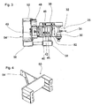
- FIG. 4 shows a perspective view of the support member 50.
- This has a substantially U-shaped main piece. From the U-base, a flange 54 projects rearward in the negative y-direction. At this flange 54, the connection with the support arm 52. The free ends of the arms of the U-shaped main piece are fixed to the stationary ring of the annular rotary union 48, as the Figures 1 and 2 demonstrate.
- FIG. 5 shows a pallet for the rotary unit 22.
- This pallet 56 is not used in practical use, in particular FIG. 7 shows. It is used for storage and transportation. It is a useful tool for transporting and storing the rotary unit 22.
- the pallet consists of two parallel tubes 58 spaced apart so that the tines of a standard forklift truck (not shown) can engage the tubes 58.
- the tubes 58 form fork tine receptacles.
- the tubes 58 are connected by spacers.
- two stops 60 are formed, which receive a U-leg of the pallet 56 between them, see also FIGS. 1 to 3 ,
- On the other tube 58 is a positioning member 62 which engages in a hole provided in the lower plate. The procedure is over FIG. 3 to see.
- the pallet 56 is offset with its geometric center with respect to the geometric center of the rotary unit 22 in the negative y-direction. It is positioned so that the center of mass of the rotary unit 22 is substantially above the center of the area of the pallet 56.
- the rotary unit 22 is connected to the support arm 52 of the cabin device 24.
- the cab device 24 allows movement in a rectangular coordinate system xs-ys-zs.
- the axis ys is parallel to the y-direction.
- movement in the ys direction can be effected by the support arm 52 facing the car 65 in this direction is extended or retracted, it is adjusted in its longitudinal direction.
- a cab device of the type used here is also referred to as an outboard device.
- An outboard device One such we offered by Peinemann, e.g. in connection with an Inside Bundle Cleaner 5 Lances (IBC-5).
- All of these movements can be controlled in the cab 65 of the cab device 24.
- the operation is carried out for example via two, preferably only a joy stick.
- FIG. 7 a small part 66 to be cleaned is shown. It is a hood.
- the high pressure cleaning device has a rotary unit 22 comprising a lance 34; a pivot unit 28 connected to the lance 34 and a nozzle rotating union 30 having a port for a high pressure supply line for supplying the lance 34; a rack 20, which is connected to the nozzle rotating passage 30 and receives the pivoting unit 28; a hydraulic pivot drive arranged on the frame 20 for the pivoting movement of the pivoting unit 28; a ring rotary leadthrough 48 having a ring rotatable about an axis of rotation parallel to the y-axis, which is connected to the frame 20 and which has a stationary ring connected to a support member 50 and a water jet Rotary feedthrough 40 and at least one, preferably two oil rotary unions 42, 44, each having annular outer parts and which are arranged one behind the other in the y-direction, are coaxial with the axis of rotation of the annular rotary union 48 and the annular outer parts are mounted on the frame 20.
Landscapes
- Cleaning By Liquid Or Steam (AREA)
- Nozzles (AREA)
- Cleaning In General (AREA)
Abstract
Description
- Die Erfindung bezieht sich auf ein Hochdruckreinigungsgerät für die Kleinteilreinigung.
- Hochdruckreinigungsgeräte sind beispielsweise aus
DE 31 41 516 A1 bekannt. Die unter einem sehr hohen Druck von über 300, insbesondere über 500 und teilweise über 1000 bar aus mindestens einer Düse austretenden Wasserstrahlen schießen und reißen Verunreinigungen vom zu reinigenden Gegenstand weg. Unter Kleinteile werden Armaturen, Schieber, Ventile, Stutzen, Rohrleitungen, Wärmetauscher, Hauben usw. verstanden. Diese Teile sind meist durch hartnäckige Verunreinigungen, beispielsweise Rückstände der chemischen und insbesondere petrochemischen Industrie, Ablagerungen von Unterbodenschutzmaterialien an Rosten aus Automobilwerken und dergleichen verschmutzt. Die Reinigungswirkung beruht hauptsächlich auf dem hohen Impuls der Wasserstrahlen, sodass Reinigungszusätze, wie z. B. Schleifkörper oder Sand im Allgemeinen nicht erforderlich sind. Letztere würden auch die ohnehin kurze Standzeit der Düsen noch weiter verringern, falls nicht besondere Maßnahmen getroffen werden. - Häufig wird die Reinigung noch manuell durchgeführt. Diese Arbeiten sind sehr gefährlich und körperlich auch sehr anstrengend. Die arbeitende Person muss durch einen aufwendigen Schutzanzug geschützt sein, dieser hemmt aber wiederum eigene Bewegungen. Da der Wasserstrahl mit hohem Druck aus der Düse austritt, kommt es zu einem erheblichen Rückimpuls, der von der Bedienperson abgefangen werden muss. Insbesondere aber ist die Gefahr von Betriebsunfällen hoch. Wenn eine Bedienperson ungewollt auf einen Körperteil zielt, ist die Gefahr eines erheblichen Unfalles gegeben, denn die Wasserstrahlen durchschlagen Körperteile.
- Eine Hochdruckreinigung der hier in Rede stehenden Art ist nicht mit dem umgangssprachlich als "kärchern" genannten Hochdruckreinigen in Privathaushalten zu vergleichen, das diese mit deutlich geringerem Druck arbeiten. Gereinigt wird in der Regel mit Wasser. Andere Reinigungsflüssigkeiten sind möglich.
- Aus der
DE 100 29 375 B4 ist eine Steuerungsvorrichtung für eine Hochdruck-Reinigungsvorrichtung bekannt. Für spezielle Anwendungsgebiete, wie beispielsweise das Reinigen von Tankinnenräumen, sind maschinell betriebene Hochdruckreinigungsvorrichtungen entwickelt worden, beispielsweise beschrieben in derDE 10131419B4 . Doch sind diese nur für geschlossene Behälter vorgesehen und nicht auf die Anwendung außerhalb übertragbar - Im Stand der Technik geht die Entwicklung hin zu Reinigungsvorrichtungen, bei denen das Bedienungspersonal entfernt vom zu reinigenden Teil ist, sich insbesondere in einer eigenen Kabine befindet. Die Lanzen bzw. Düsen werden nicht mehr direkt vom Bedienenden geführt, vielmehr über Steuervorrichtungen und Motoren ausgerichtet. Dabei wird eine Bewegungsmöglichkeit in mehreren Richtungen erwünscht. Es müssen auch komplizierte Teile, beispielsweise mit Hinterschneidungen gereinigt werden können.
- Eine Teilautomation der Reinigung ist bereits bekannt. Es fehlt dabei zumeist eine ausreichende Bewegungsfreiheit um ausreichend viele Achsen bzw. in ausreichend vielen Richtungen, so dass beliebige, auch komplizierte Teile gereinigt werden können.
- Aufgabe der Erfindung ist es, eine Hochdruckreinigungsvorrichtung für die Reinigung von Kleinteilen zur Verfügung zu stellen, die das Reinigungspersonal entlastet, die Risiken beseitigt oder zumindest stark verringert und zur Reinigung von unterschiedlichsten Teilen, also von Oberflächen, aber auch zum universellen Einsatz geeignet ist.
- Diese Aufgabe wird gelöst durch ein Hochdruck-Reinigungsvorrichtung für verschmutzte Kleinteile, mit einer Dreheinheit aufweisend, a) eine Lanze, die ein Austrittsende für eine Düse und ein Eintrittsende hat, b) eine Schwenkeinheit, die mit der Lanze verbunden ist, um eine quer zur Lanze verlaufende z-Richtung schwenkbar ist und eine Düsen-Drehdurchführung aufweist, welche einen Anschluss für eine Hochdruckzuleitung zur Versorgung der Lanze aufweist, c) ein Gestell, das mit der Düsen-Drehdurchführung verbunden ist und die Schwenkeinheit aufnimmt, d) einen am Gestell angeordneten hydraulischen Schwenkantrieb für die Schwenkbewegung der Schwenkeinheit, e) eine Ring-Drehdurchführung, die einen um eine Rotationsachse, die parallel zur y-Achse ist, drehbaren Ring hat, der mit dem Gestell verbunden ist, und die einen stationären Ring hat, der mit einem Tragteil verbunden ist und f) eine Wasser-Drehdurchführung und mindestens eine, vorzugsweise zwei Öl-Drehdurchführungen, die in y-Richtung hintereinander angeordnet sind, achsgleich mit der Rotationsachse der Ring-Drehdurchführung sind und deren Außenteile am Gestell festgelegt sind.
- Weiterbildungen finden sich in den Unteransprüchen. Zu Hochdruckschläuchen wird auf
DE 20 1210 206 485 verwiesen. - Ein Ausführungsbeispiel der Erfindung, das nicht einschränkend zu verstehen ist, wird im Folgenden unter Bezugnahme auf die Zeichnung näher erläutert. In dieser Zeichnung zeigen:
-
Figur 1 : eine perspektivische Ansicht einer Dreheinheit der Reinigungsvorrichtung, -
Figur 2 : eine Draufsicht auf die Dreheinheit gemäßFigur 1 , gesehen in negativer z-Richtung, -
Figur 3 : eine Seitenansicht der Dreheinheit gemäßFigur 1 , gesehen in negativer x-Richtung, -
Figur 4 : eine perspektivische Ansicht eines Tragteils der Dreheinheit, -
Figur 5 : eine rückwärtige Ansicht der Dreheinheit, gesehen in positiver y-Richtung, -
Figur 6 : eine perspektivische Darstellung einer Palette für die Dreheinheit und -
Figur 7 : eine perspektivische Darstellung der Reinigungsvorrichtung mit Dreheinheit und Kabinenvorrichtung, weiterhin ist ein zu reinigendes Kleinteil dargestellt. - Für die Beschreibung wird ein rechtshändiges xyz-Koordinatensystem verwendet, wie es in
Figur 1 dargestellt ist. Es ist auf ein Gestell 20 einer Dreheinheit 22 bezogen. Dieses Koordinatensystem ist nicht ortsfest, da das Gestell 20 bei einem Reinigungsvorgang durch eine Kabinenvorrichtung 24, wie sie inFigur 7 gezeigt ist, in drei Richtungen bewegt und zudem durch eine Ring-Drehdurchführung 48 gedreht wird. - Das Gestell 20 hat vorn zwei in y-Richtung vorstehende, parallel zueinander verlaufende Zungen 26, deren Zungenfläche parallel zur xy-Ebene verläuft. Zwischen diesen zwei Zungen 26 ist eine Schwenkeinheit 28 angeordnet. Sie hat eine Düsen-Drehdurchführung 30, deren stationärer Teil mit der unteren Zunge fest verbunden ist und deren drehbarer Teil mit einem Schwenkrohr 32 verbunden ist, das oben in der anderen Zunge drehbar gelagert ist. Das Schwenkrohr 32 verläuft parallel zur z-Richtung. Am Schwenkrohr 32 ist quer dazu eine Lanze 34 angeordnet, sie hat ein Eintrittsende, über dieses kommuniziert sie mit dem Schwenkrohr 32. An einem freien Austrittsende der Lanze 34 ist eine Aufnahme für eine Düse (nicht dargestellt) ausgebildet. Hier können unterschiedliche Düsen angesetzt werden, auch Mehrfachdüsen. Es können Düsen nach dem Stand der Technik benutzt werden.
- Die beiden genannten Zungen 26 gehen in negativer y-Richtung jeweils einstückig in Platten über. Auf der oberen Platte ist ein hydraulischer Schwenkantrieb angeordnet, er weist einen doppelt wirkenden Hydraulikzylinder 36 auf. Dieser ist, wie
Figur 2 , bei der im Unterschied zuFig. 1 eine obere Abdeckung entfernt ist, erkennen lässt, an einem hinteren Ende mit der oberen Platte gelenkverbunden. An einem vorderen Ende ist er an einem Kurbelarm 38 angelenkt, der wiederum mit dem Schwenkrohr 32 drehverbunden ist. Auf diese Weise kann das Schwenkrohr 32 um einen Winkel aus der in denFiguren 1 bis 3 gezeigten Mittelstellung geschwenkt werden. Die Mittelstellung ist parallel zur y-Richtung. Sie ist eine Endstellung. - Ausgehend von der Stellung der Lanze 34 in y-Richtung wie in
Figur 2 wird der Winkelbereich im negativen Uhrzeigersinn bis zu - 140° erreicht, wenn der Hydraulikzylinder 36 betätigt wird. Der andere Winkelbereich ausgehend von der gezeigten Position in Richtung des Uhrzeigersinnes bis zu etwa + 140° wird dadurch erreicht, dass das Gestell 20 um 180° um die y-Achse gedreht wird, hierauf wird später noch eingegangen. - Zwischen den beiden Platten sind insgesamt drei Drehdurchführungen 40, 42 und 44 achsgleich und in Achsrichtung (= y-Richtung) hintereinander angeordnet, nämlich eine Wasserdrehdurchführung 40, eine erste Öl-Drehdurchführung 42 und eine zweite Öl-Drehdurchführung 44. Die ringförmigen Außenteile dieser Drehdurchführungen 40 bis 44 sind stationär bezüglich des Gestells 20, sie drehen sich relativ zu den in den Figuren nicht ersichtlichen Innenteilen, hierauf wird später eingegangen. Die Außenteile sind jeweils über hier nicht dargestellte Zuleitungen angeschlossen, die Wasser-Drehdurchführung 40 ist über eine Zuleitung mit dem stationären Teil der Düsen-Drehdurchführung 30 verbunden, jede der beiden Öl-Drehdurchführungen 42, 44 ist über eine Zuleitung mit einem Anschluss 46 des Hydraulikzylinders 36 verbunden. Die Wasser-Zuleitung ist stationär, die beiden Zuleitungen für Öl bewegen sich geringfügig bei einer Schwenkbewegung. Für den Kurbelarm 38 bzw. das Gelenk zwischen Kurbelarm und Hydraulikzylinder 36 sind zwei Anschläge auf der oberen Platte vorgesehen. Sie sind einstellbar.
- Zur Dreheinheit gehört weiterhin die Ring-Drehdurchführung 48. Hier wird ein Bauteil Rotobox der Firma HKS verwendet. Sie hat eine drehbaren Ring, der mit dem Gestell 20 verbunden ist, und einen stationären Ring. Die Innenteile der Drehdurchführungen 40 bis 44 sind mit dem stationären Ring der Ring-Drehdurchführung 48 verbunden. Bei einer Drehbewegung der Ring-Drehdurchführung 48 drehen sich daher die ringförmigen Außenteile der Drehdurchführungen 40 bis 44.
- Die hier nicht dargestellten Versorgungsleitungen für Wasser bzw. Öl laufen von den Innenteilen der Drehdurchführungen 40 bis 44 durch einen Ringraum der Ring-Drehdurchführung 48 zu einer Abschlussplatte 49, die den Ringraum nach hinten abschließt. An ihr enden die Versorgungsleitungen in Kupplungen, an denen Schläuche angeschlossen werden können. Die Innenteile der Drehdurchführungen 40 bis 44 sind mit der Abschlussplatte 49 über Leitungen verbunden. Die Innenteile und die Leitungen können in negativer y-Richtung herausgezogen werden, wenn die Abschlussplatte 49 vom stationären Ring gelöst ist. Die Wasser-Drehdurchführung 40 und die mindestens eine Öl-Drehdurchführung 40, 42 sind auf einer Seite der Ring-Drehdurchführung 48 angeordnet, die Abschlussplatte 49 ist auf der anderen, axial gegenüberliegenden Seite der Ring-Drehdurchführung 48 angeordnet. Die Wasser-Drehdurchführung 40 und die mindestens eine Öl-Drehdurchführung 40, 42 befinden sich außerhalb des Ringraums der Ring-Drehdurchführung 48. Die Abschlussplatte 49 befindet sich außerhalb des Ringraums der Ring-Drehdurchführung 48.
- Am stationären Ring der Ring-Drehdurchführung 48 ist ein Tragteil 50 befestigt. Es ist in
Fig. 4 dargestellt. Über dieses Tragteil 50 erfolgt die Verbindung mit einem Tragarm 52, sieheFigur 7 . Das Tragteil hat einen Flansch 54, er ist mit dem Tragarm 52 lösbar verbunden. - Die Ring-Drehdurchführung 48 wird über einen Hydraulikmotor angetrieben, es liegen für sie zwei Zuleitungen vor, die am stationären Teil der Ring-Drehdurchführung 48 angesetzt sind. Sie versorgen den Hydraulikmotor in der Rechts- bzw. Linksrichtung. Damit sind insgesamt fünf Versorgungsleitungen für die Dreheinheit 22 vorgesehen, nämlich zwei Öl-Versorgungsleitungen für die Ring-Drehdurchführung 48, zwei Öl-Versorgungsleitungen für die beiden Öl-Drehdurchführungen 42 und 44 und eine Wasser-Versorgungsleitung für die Lanze 34. Alle diese Zuleitungen sind stationär und führen keinerlei Bewegung durch, wenn die Ring-Drehdurchführung 48 gedreht oder die Schwenkeinheit 28 betätigt wird. Sie werden jedoch bewegt, wenn die Kabinenvorrichtung 24 bewegt wird.
- Die Ring-Drehdurchführung 48 hat eine Rotationsachse, die parallel zur y-Achse verläuft. Die Drehdurchführungen 40 bis 44 sind zentrisch zu dieser Drehachse angeordnet. Die Drehachse schneidet das Schwenkrohr 32 mittig und im rechten Winkel.
- Hält man die Dreheinheit 22 am Tragteil 50 fest, wie dies durch die Befestigung am Tragarm 52 erfolgt, so können folgende Bewegungen durchgeführt werden: Bei Betätigung der Schwenkeinheit 28 wird die Lanze 34 in einem Winkelbereich von 0 bis plus oder minus 140° verschwenkt. Bei Betätigung der Ring-Drehdurchführung 48 erfolgt eine Drehung des Gestells 20 der Dreheinheit 22 um die Rotationsachse. Diese Drehung kann um beliebige Winkel durchgeführt werden
-
Figur 4 zeigt eine perspektivische Darstellung des Tragteils 50. Dieses hat ein im Wesentlichen U-förmiges Hauptstück. Von der U-Basis steht ein Flansch 54 nach hinten in negativer y-Richtung weg. An diesem Flansch 54 erfolgt die Verbindung mit dem Tragarm 52. Die freien Enden der Arme des U-förmige Hauptstücks werden am stationären Ring der Ring-Drehdurchführung 48 festgelegt, wie dies dieFiguren 1 und 2 zeigen. -
Figur 5 zeigt eine Palette für die Dreheinheit 22. Diese Palette 56 wird im praktischen Einsatz nicht verwendet, wie insbesondereFigur 7 zeigt. Sie wird für Lagerung und Transport verwendet. Sie ist ein nützliches Hilfsmittel für den Transport und die Aufbewahrung der Dreheinheit 22. Die Palette besteht aus zwei zueinander parallelen Rohren 58, die in einem Abstand voneinander gehalten sind, sodass die Zinken eines normalen Gabelstaplers (nicht dargestellt) in die Rohre 58 greifen können. Die Rohre 58 bilden Gabelzinkenaufnahmen. Die Rohre 58 sind durch Abstandsstücke miteinander verbunden. Auf der Oberseite eines Rohres 58 sind zwei Anschläge 60 ausgebildet, die zwischen sich einen U-Schenkel der Palette 56 aufnehmen, siehe auchFiguren 1 bis 3 . Auf dem anderen Rohr 58 befindet sich ein Positionierteil 62, das in ein Loch greift, welches in der unteren Platte vorgesehen ist. Der Eingriff ist ausFigur 3 zu ersehen. - Die Palette 56 ist mit ihrem geometrischen Mittelpunkt gegenüber dem geometrischen Mittelpunkt der Dreheinheit 22 in negativer y-Richtung versetzt. Sie ist so positioniert, dass der Massenmittelpunkt der Dreheinheit 22 im Wesentlichen über der Flächenmitte der Palette 56 liegt.
- In
Figur 7 ist das Hochdruckreinigungsgerät insgesamt dargestellt. Die Dreheinheit 22 ist mit dem Tragarm 52 der Kabinenvorrichtung 24 verbunden. Die Kabinenvorrichtung 24 ermöglicht eine Bewegung in einem rechtwinkligen Koordinatensystem xs-ys-zs. Die Achse ys ist parallel zur y-Richtung. Durch Bewegung einer Kabine 65 und des Tragarms 52 entlang der Schienen 64 erfolgt eine Verschiebung des Gestells 20 entlang der xs-Richtung, also seitlich. Eine Bewegung in zs-Richtung erfolgt durch eine Aufwärts- oder Abwärtsbewegung (=hoch, tief) der Kabine 65 und mit dem Tragarm 52. Weiterhin kann eine Bewegung in ys-Richtung dadurch erfolgen, dass der Tragarm 52 gegenüber der Kabine 65 in dieser Richtung ein- oder ausgefahren wird, er wird dabei in seiner Längsrichtung verstellt. - Eine Kabinenvorrichtung der hier eingesetzten Art wird auch als Außenseitengerät bezeichnet. Ein solches wir von der Firma Peinemann angeboten, z.B. im Zusammenhang mit einem Inside Bundle Cleaner 5 Lances (IBC-5).
- Alle diese Bewegungen einschließlich der Bewegungen der Dreheinheit 22 können in der Kabine 65 der Kabinenvorrichtung 24 gesteuert werden. Die Betätigung erfolgt beispielsweise über zwei, vorzugsweise über nur einen Joy-Stick.
- Schließlich ist in
Figur 7 noch ein zu reinigendes Kleinteil 66 gezeigt. Es handelt sich um eine Haube. - Die Hochdruck-Reinigungsvorrichtung hat eine Dreheinheit 22 aufweisend eine Lanze 34; eine Schwenkeinheit 28, die mit der Lanze 34 verbunden ist und eine Düsen-Drehdurchführung 30, welche einen Anschluss für eine Hochdruckzuleitung zur Versorgung der Lanze 34 aufweist; ein Gestell 20, das mit der Düsen-Drehdurchführung 30 verbunden ist und die Schwenkeinheit 28 aufnimmt; einen am Gestell 20 angeordneten hydraulischen Schwenkantrieb für die Schwenkbewegung der Schwenkeinheit 28; eine Ring-Drehdurchführung 48, die einen um eine Rotationsachse, die parallel zur y-Achse ist, drehbaren Ring hat, der mit dem Gestell 20 verbunden ist, und die einen stationären Ring hat, der mit einem Tragteil 50 verbunden ist und eine Wasser-Drehdurchführung 40 und mindestens eine, vorzugsweise zwei Öl-Drehdurchführungen 42, 44, die jeweils ringförmige Außenteile aufweisen und die in y-Richtung hintereinander angeordnet sind, achsgleich mit der Rotationsachse der Ring-Drehdurchführung 48 sind und deren ringförmige Außenteile am Gestell 20 befestigt sind.
-
- 20
- Gestell
- 22
- Dreheinheit
- 24
- Kabinenvorrichtung
- 26
- Zunge
- 28
- Schwenkeinheit
- 30
- Düsen-Drehdurchführung
- 32
- Schwenkrohr
- 34
- Lanze
- 36
- Hydraulikzylinder
- 38
- Kurbelarm
- 40
- Wasser-Drehdurchführung
- 42
- 1. Öl-Drehdurchführung
- 44
- 2. Öl-Drehdurchführung
- 46
- Anschluß
- 48
- Ring-Drehdurchführung
- 49
- Abschlussplatte
- 50
- Tragteil
- 52
- Tragarm
- 54
- Flansch
- 56
- Palette
- 58
- Rohr
- 60
- Anschlag
- 62
- Positionierteil
- 64
- Schienen
- 65
- Kabine
- 66
- Kleinteil
Claims (12)
- Hochdruck-Reinigungsvorrichtung für verschmutzte Kleinteile (66), mit einer Dreheinheit (22) aufweisend,- eine Lanze (34), die ein Austrittsende für eine Düse und ein Eintrittsende hat,- eine Schwenkeinheit (28), die mit der Lanze (34) verbunden ist, um eine quer zur Lanze (34) verlaufende z-Richtung schwenkbar ist und eine Düsen-Drehdurchführung (30) aufweist, welche einen Anschluss für eine Hochdruckzuleitung zur Versorgung der Lanze (34) aufweist,- ein Gestell (20), das die Schwenkeinheit (28) aufnimmt,- einen am Gestell (20) angeordneten hydraulischen Schwenkantrieb für die Schwenkbewegung der Schwenkeinheit (28),- eine Ring-Drehdurchführung (48), die einen um eine Rotationsachse, die parallel zur y-Achse ist, drehbaren Ring hat, der mit dem Gestell (20) verbunden ist, und die einen stationären Ring hat, der mit einem Tragteil (50) verbunden ist und- eine Wasser-Drehdurchführung (40) und mindestens eine, vorzugsweise zwei Öl-Drehdurchführungen (42, 44), die jeweils ringförmige Außenteile aufweisen und die in y-Richtung hintereinander angeordnet sind, achsgleich mit der Rotationsachse der Ring-Drehdurchführung (48) sind und deren ringförmige Außenteile am Gestell (20) festgelegt sind.
- Hochdruckreinigungsvorrichtung nach Anspruch 1, dadurch gekennzeichnet, dass sie weiterhin eine Kabinenvorrichtung (24) aufweist, dass die Kabinenvorrichtung (24) einen Tragarm (52) hat, an dessen freiem Ende das Tragteil (50) lösbar befestigt ist, dass die Kabinenvorrichtung (24) eine Kabine (65) aufweist, in der eine Steuervorrichtung angeordnet ist, dass die Kabinenvorrichtung (24) eine Verstellvorrichtung aufweist, und dass der Tragarm (52) mit einer Verstellvorrichtung verbunden ist, die eine Verstellung des Tragarms (52) a) hoch, tief, b) seitlich und c) in seiner Längsrichtung vorsieht.
- Hochdruckreinigungsvorrichtung nach Anspruch 1, dadurch gekennzeichnet, dass der Tragarm (52) in drei voneinander unabhängigen Bewegungsrichtungen verstellbar ist.
- Hochdruckreinigungsvorrichtung nach einem der vorangegangenen Ansprüche, dadurch gekennzeichnet, dass sie weiterhin eine Palette (56) aufweist, dass die Palette (56) zwei in x-Richtung verlaufende, parallele Gabelzinkenaufnahmen, eine Stütze für das Tragteil (50) und einen Positioniervorsprung (62) passend zu einer Ausnehmung im Gestell (20) aufweist.
- Hochdruckreinigungsvorrichtung nach einem der vorangegangenen Ansprüche, dadurch gekennzeichnet, dass der hydraulische Schwenkantrieb einen doppelt wirkenden Hydraulikzylinder (36) aufweist, der zwei Anschlüsse (46) aufweist, und dass jeder Anschluss (46) über eine Zuleitung mit einem Ausgang einer der insgesamt zwei Öl-Durchführungen (40, 42) verbunden ist.
- Hochdruckreinigungsvorrichtung nach einem der vorangegangenen Ansprüche, dadurch gekennzeichnet, dass ein eingangsseitiger Anschluss der Wasser-Drehdurchführung (40) und der mindestens einen Öl-Drehdurchführung (40, 42) mit einer Versorgungsleitung verbunden ist, dass die Versorgungsleitungen durch einen Ringraum der Ring-Drehdurchführung (48) geführt sind und in einer Abschlussplatte (49) festgelegt sind, die mit dem stationären Ring der Ring-Drehdurchführung (48) verbunden ist.
- Hochdruckreinigungsvorrichtung nach einem der vorangegangenen Ansprüche, dadurch gekennzeichnet, dass das Gestell (20) zwei vorspringende Zungen (26) hat, die parallel zueinander verlaufen und zwischen denen das Schwenkrohr (32) der Schwenkeinheit (28) angeordnet ist.
- Hochdruckreinigungsvorrichtung nach einem der vorangegangenen Ansprüche, dadurch gekennzeichnet, dass die Rotationsachse der Ring-Drehdurchführung (48) die Schwenkachse der Schwenkeinheit (28) im rechten Winkel schneidet.
- Hochdruckreinigungsvorrichtung nach einem der vorangegangenen Ansprüche, dadurch gekennzeichnet, dass die Schwenkeinheit (28) einen doppelt wirkenden Hydraulikzylinder (36) aufweist, der an seinem einen Ende am Gestell (20) angelenkt ist und an seinem anderen Ende über einen Kurbelarm (38) mit dem Schwenkrohr (32) der Schwenkeinheit (28) drehverbunden ist.
- Hochdruckreinigungsvorrichtung nach einem der vorangegangenen Ansprüche, dadurch gekennzeichnet, dass eine Abschlussplatte (49) vorgesehen ist, die am stationären Ring der Ring-Drehdurchführung (48) befestigt ist und einen Ringraum der Ring-Drehdurchführung (48) nach hinten abschließt, und dass vorzugsweise Kupplungsstücke an der Abschlussplatte (49) festgelegt sind, die mit Zuleitungen für Drehdurchführungen und Aktuatoren, wie z.B. ein Hydraulikzylinder (36), kommunizieren.
- Hochdruckreinigungsvorrichtung nach einem der vorangegangenen Ansprüche, dadurch gekennzeichnet, dass eine Abschlussplatte (49) vorgesehen ist, und dass ringförmige Innenteile der Wasser-Drehdurchführung (40) und der mindestens einen Öl-Drehdurchführung (40, 42) an der Abschlussplatte (49) befestigt sind.
- Hochdruckreinigungsvorrichtung nach einem der vorangegangenen Ansprüche, dadurch gekennzeichnet, dass eine Abschlussplatte (49) vorgesehen ist, dass die Wasser-Drehdurchführung (40) und die mindestens eine Öl-Drehdurchführung (40, 42) auf einer Seite der Ring-Drehdurchführung (48) angeordnet sind und die Abschlussplatte (49) auf der anderen, axial gegenüberliegenden Seite der Ring-Drehdurchführung (48) angeordnet ist.
Applications Claiming Priority (1)
| Application Number | Priority Date | Filing Date | Title |
|---|---|---|---|
| DE102015112364 | 2015-07-29 |
Publications (2)
| Publication Number | Publication Date |
|---|---|
| EP3124127A1 true EP3124127A1 (de) | 2017-02-01 |
| EP3124127B1 EP3124127B1 (de) | 2019-01-09 |
Family
ID=56511451
Family Applications (1)
| Application Number | Title | Priority Date | Filing Date |
|---|---|---|---|
| EP16181045.2A Active EP3124127B1 (de) | 2015-07-29 | 2016-07-25 | Hochdruckreinigungsgerät für die kleinteilreinigung |
Country Status (1)
| Country | Link |
|---|---|
| EP (1) | EP3124127B1 (de) |
Citations (9)
| Publication number | Priority date | Publication date | Assignee | Title |
|---|---|---|---|---|
| DE3141516A1 (de) | 1981-10-20 | 1983-05-05 | Richard Buchen GmbH, 5000 Köln | Hochdruck-reinigungsvorrichtung fuer wasserdrucke von etwa 300 bis 500 bar und darueber |
| US4647076A (en) * | 1985-10-15 | 1987-03-03 | Amtel, Inc. | High pressure fluid swivel |
| DE3609876A1 (de) * | 1986-03-22 | 1987-09-24 | Blohm Voss Ag | Rohrdrehgelenk oder swivel |
| US5462227A (en) * | 1994-08-18 | 1995-10-31 | Ping; Wu K. | Automatic cleaning device for use on a stock farm |
| DE10029375B4 (de) | 2000-06-20 | 2004-04-29 | Hammelmann Maschinenfabrik Gmbh | Steuerungsvorrichtung für eine Hochdruck-Reinigungsvorrichtung |
| EP1439003A1 (de) * | 2003-01-15 | 2004-07-21 | Alto Danmark A/S | Hochdruckreinigungsgerät |
| DE10131419B4 (de) | 2001-06-29 | 2004-12-02 | Lobbe Tankschutz Gmbh | Vorrichtung und Verfahren zum Reinigen von Tanks zur Lagerung von Rohöl |
| DE202007006113U1 (de) * | 2007-04-26 | 2007-07-12 | Rst Regel- Und Steuerungsanlagen Gmbh | Hochdrucksystem zur Reinigung von Oberflächen mittels eines Hochdruckflüssigkeitsstrahls |
| DE102013101496A1 (de) * | 2013-02-14 | 2014-08-14 | Hammelmann Maschinenfabrik Gmbh | Verfahren zur Oberflächenbehandlung eines formstabilen Körpers sowie Vorrichtung zur Durchführung des Verfahrens |
-
2016
- 2016-07-25 EP EP16181045.2A patent/EP3124127B1/de active Active
Patent Citations (9)
| Publication number | Priority date | Publication date | Assignee | Title |
|---|---|---|---|---|
| DE3141516A1 (de) | 1981-10-20 | 1983-05-05 | Richard Buchen GmbH, 5000 Köln | Hochdruck-reinigungsvorrichtung fuer wasserdrucke von etwa 300 bis 500 bar und darueber |
| US4647076A (en) * | 1985-10-15 | 1987-03-03 | Amtel, Inc. | High pressure fluid swivel |
| DE3609876A1 (de) * | 1986-03-22 | 1987-09-24 | Blohm Voss Ag | Rohrdrehgelenk oder swivel |
| US5462227A (en) * | 1994-08-18 | 1995-10-31 | Ping; Wu K. | Automatic cleaning device for use on a stock farm |
| DE10029375B4 (de) | 2000-06-20 | 2004-04-29 | Hammelmann Maschinenfabrik Gmbh | Steuerungsvorrichtung für eine Hochdruck-Reinigungsvorrichtung |
| DE10131419B4 (de) | 2001-06-29 | 2004-12-02 | Lobbe Tankschutz Gmbh | Vorrichtung und Verfahren zum Reinigen von Tanks zur Lagerung von Rohöl |
| EP1439003A1 (de) * | 2003-01-15 | 2004-07-21 | Alto Danmark A/S | Hochdruckreinigungsgerät |
| DE202007006113U1 (de) * | 2007-04-26 | 2007-07-12 | Rst Regel- Und Steuerungsanlagen Gmbh | Hochdrucksystem zur Reinigung von Oberflächen mittels eines Hochdruckflüssigkeitsstrahls |
| DE102013101496A1 (de) * | 2013-02-14 | 2014-08-14 | Hammelmann Maschinenfabrik Gmbh | Verfahren zur Oberflächenbehandlung eines formstabilen Körpers sowie Vorrichtung zur Durchführung des Verfahrens |
Also Published As
| Publication number | Publication date |
|---|---|
| EP3124127B1 (de) | 2019-01-09 |
Similar Documents
| Publication | Publication Date | Title |
|---|---|---|
| DE3650545T2 (de) | Freibewegbares Reinigungsgerät für Rohrbündel | |
| EP0162309B1 (de) | Vorrichtung zum Reinigen radioaktiv kontaminierter Rohrbündel | |
| DE2544874A1 (de) | Reinigungsverfahren und -geraet zum entfernen von material von den waenden eines behaelters | |
| DE19751292C1 (de) | Vorrichtung zum Schutz von Verbindungselementen an Baugeräten vor Schmutz und Spritzwasser | |
| WO2018046456A1 (de) | Vorrichtung und verfahren zum reinigen der oberfläche eines werkzeugs | |
| DE3621717C2 (de) | Industrieroboter | |
| DE2901599C2 (de) | Reinigungsvorrichtung für Müllbehälter o.dgl. | |
| CH675620A5 (de) | ||
| DE112017000110B4 (de) | Reinigungsmaschine mit zwei Roboterarmen und zugehöriges Reinigungsverfahren | |
| EP2754507A1 (de) | Mobile Hochdruckreinigungsvorrichtung | |
| EP3124127B1 (de) | Hochdruckreinigungsgerät für die kleinteilreinigung | |
| DE202011110688U1 (de) | Industrierobotersystem | |
| DE2544829A1 (de) | Wasserstrahlgeraet | |
| DE202009018738U1 (de) | Leicht lösbares Kupplungssystem zur axialen Kupplung von zwei Flanschen | |
| DE19911382B4 (de) | Werkzeugführungssystem | |
| DE380896C (de) | Beregnungsanlage mit von einer Feldleitung abgehenden Zweigleitungen | |
| DE102019006362A1 (de) | Vorrichtung zum Zuführen eines Mediums zu einem Werkzeug einer Bearbeitungsmaschine und Verfahren zum Bereitstellen einer derartigen Vorrichtung | |
| DE3305260A1 (de) | Fahrbare tankreinigungsanlage | |
| DE3307167C2 (de) | Innenreinigungsvorrichtung für längliche Behälter | |
| DE102018130802B3 (de) | Vorrichtung zur Ausführung von Arbeitsvorgängen in Lagertanks für Erdölprodukte | |
| DE2426151B2 (de) | Gelenkrohrverbindung für hohe Beanspruchung | |
| DE102021119703B4 (de) | Antrieb für einen Greifer, Greifer und Baumaschine | |
| DE202009017910U1 (de) | Vorrichtung zum Reinigen von Düsen eines Schweißbrenners | |
| EP3793870B1 (de) | Fahrzeugwaschanlage mit einer sprühvorrichtung | |
| EP4401920A1 (de) | Vorrichtung für kanalrohrarbeiten |
Legal Events
| Date | Code | Title | Description |
|---|---|---|---|
| PUAI | Public reference made under article 153(3) epc to a published international application that has entered the european phase |
Free format text: ORIGINAL CODE: 0009012 |
|
| STAA | Information on the status of an ep patent application or granted ep patent |
Free format text: STATUS: THE APPLICATION HAS BEEN PUBLISHED |
|
| STAA | Information on the status of an ep patent application or granted ep patent |
Free format text: STATUS: REQUEST FOR EXAMINATION WAS MADE |
|
| AK | Designated contracting states |
Kind code of ref document: A1 Designated state(s): AL AT BE BG CH CY CZ DE DK EE ES FI FR GB GR HR HU IE IS IT LI LT LU LV MC MK MT NL NO PL PT RO RS SE SI SK SM TR |
|
| AX | Request for extension of the european patent |
Extension state: BA ME |
|
| 17P | Request for examination filed |
Effective date: 20170113 |
|
| RBV | Designated contracting states (corrected) |
Designated state(s): AL AT BE BG CH CY CZ DE DK EE ES FI FR GB GR HR HU IE IS IT LI LT LU LV MC MK MT NL NO PL PT RO RS SE SI SK SM TR |
|
| GRAP | Despatch of communication of intention to grant a patent |
Free format text: ORIGINAL CODE: EPIDOSNIGR1 |
|
| STAA | Information on the status of an ep patent application or granted ep patent |
Free format text: STATUS: GRANT OF PATENT IS INTENDED |
|
| GRAJ | Information related to disapproval of communication of intention to grant by the applicant or resumption of examination proceedings by the epo deleted |
Free format text: ORIGINAL CODE: EPIDOSDIGR1 |
|
| STAA | Information on the status of an ep patent application or granted ep patent |
Free format text: STATUS: REQUEST FOR EXAMINATION WAS MADE |
|
| GRAP | Despatch of communication of intention to grant a patent |
Free format text: ORIGINAL CODE: EPIDOSNIGR1 |
|
| STAA | Information on the status of an ep patent application or granted ep patent |
Free format text: STATUS: GRANT OF PATENT IS INTENDED |
|
| INTG | Intention to grant announced |
Effective date: 20180411 |
|
| INTG | Intention to grant announced |
Effective date: 20180507 |
|
| GRAS | Grant fee paid |
Free format text: ORIGINAL CODE: EPIDOSNIGR3 |
|
| GRAJ | Information related to disapproval of communication of intention to grant by the applicant or resumption of examination proceedings by the epo deleted |
Free format text: ORIGINAL CODE: EPIDOSDIGR1 |
|
| GRAL | Information related to payment of fee for publishing/printing deleted |
Free format text: ORIGINAL CODE: EPIDOSDIGR3 |
|
| STAA | Information on the status of an ep patent application or granted ep patent |
Free format text: STATUS: REQUEST FOR EXAMINATION WAS MADE |
|
| GRAP | Despatch of communication of intention to grant a patent |
Free format text: ORIGINAL CODE: EPIDOSNIGR1 |
|
| STAA | Information on the status of an ep patent application or granted ep patent |
Free format text: STATUS: GRANT OF PATENT IS INTENDED |
|
| INTC | Intention to grant announced (deleted) | ||
| INTG | Intention to grant announced |
Effective date: 20180914 |
|
| GRAA | (expected) grant |
Free format text: ORIGINAL CODE: 0009210 |
|
| STAA | Information on the status of an ep patent application or granted ep patent |
Free format text: STATUS: THE PATENT HAS BEEN GRANTED |
|
| AK | Designated contracting states |
Kind code of ref document: B1 Designated state(s): AL AT BE BG CH CY CZ DE DK EE ES FI FR GB GR HR HU IE IS IT LI LT LU LV MC MK MT NL NO PL PT RO RS SE SI SK SM TR |
|
| REG | Reference to a national code |
Ref country code: GB Ref legal event code: FG4D Free format text: NOT ENGLISH |
|
| REG | Reference to a national code |
Ref country code: AT Ref legal event code: REF Ref document number: 1086659 Country of ref document: AT Kind code of ref document: T Effective date: 20190115 Ref country code: CH Ref legal event code: EP |
|
| REG | Reference to a national code |
Ref country code: DE Ref legal event code: R096 Ref document number: 502016003117 Country of ref document: DE |
|
| REG | Reference to a national code |
Ref country code: IE Ref legal event code: FG4D Free format text: LANGUAGE OF EP DOCUMENT: GERMAN |
|
| REG | Reference to a national code |
Ref country code: NL Ref legal event code: FP |
|
| REG | Reference to a national code |
Ref country code: LT Ref legal event code: MG4D |
|
| PG25 | Lapsed in a contracting state [announced via postgrant information from national office to epo] |
Ref country code: FI Free format text: LAPSE BECAUSE OF FAILURE TO SUBMIT A TRANSLATION OF THE DESCRIPTION OR TO PAY THE FEE WITHIN THE PRESCRIBED TIME-LIMIT Effective date: 20190109 Ref country code: NO Free format text: LAPSE BECAUSE OF FAILURE TO SUBMIT A TRANSLATION OF THE DESCRIPTION OR TO PAY THE FEE WITHIN THE PRESCRIBED TIME-LIMIT Effective date: 20190409 Ref country code: PT Free format text: LAPSE BECAUSE OF FAILURE TO SUBMIT A TRANSLATION OF THE DESCRIPTION OR TO PAY THE FEE WITHIN THE PRESCRIBED TIME-LIMIT Effective date: 20190509 Ref country code: PL Free format text: LAPSE BECAUSE OF FAILURE TO SUBMIT A TRANSLATION OF THE DESCRIPTION OR TO PAY THE FEE WITHIN THE PRESCRIBED TIME-LIMIT Effective date: 20190109 Ref country code: SE Free format text: LAPSE BECAUSE OF FAILURE TO SUBMIT A TRANSLATION OF THE DESCRIPTION OR TO PAY THE FEE WITHIN THE PRESCRIBED TIME-LIMIT Effective date: 20190109 Ref country code: LT Free format text: LAPSE BECAUSE OF FAILURE TO SUBMIT A TRANSLATION OF THE DESCRIPTION OR TO PAY THE FEE WITHIN THE PRESCRIBED TIME-LIMIT Effective date: 20190109 Ref country code: ES Free format text: LAPSE BECAUSE OF FAILURE TO SUBMIT A TRANSLATION OF THE DESCRIPTION OR TO PAY THE FEE WITHIN THE PRESCRIBED TIME-LIMIT Effective date: 20190109 |
|
| PG25 | Lapsed in a contracting state [announced via postgrant information from national office to epo] |
Ref country code: GR Free format text: LAPSE BECAUSE OF FAILURE TO SUBMIT A TRANSLATION OF THE DESCRIPTION OR TO PAY THE FEE WITHIN THE PRESCRIBED TIME-LIMIT Effective date: 20190410 Ref country code: IS Free format text: LAPSE BECAUSE OF FAILURE TO SUBMIT A TRANSLATION OF THE DESCRIPTION OR TO PAY THE FEE WITHIN THE PRESCRIBED TIME-LIMIT Effective date: 20190509 Ref country code: BG Free format text: LAPSE BECAUSE OF FAILURE TO SUBMIT A TRANSLATION OF THE DESCRIPTION OR TO PAY THE FEE WITHIN THE PRESCRIBED TIME-LIMIT Effective date: 20190409 Ref country code: HR Free format text: LAPSE BECAUSE OF FAILURE TO SUBMIT A TRANSLATION OF THE DESCRIPTION OR TO PAY THE FEE WITHIN THE PRESCRIBED TIME-LIMIT Effective date: 20190109 Ref country code: LV Free format text: LAPSE BECAUSE OF FAILURE TO SUBMIT A TRANSLATION OF THE DESCRIPTION OR TO PAY THE FEE WITHIN THE PRESCRIBED TIME-LIMIT Effective date: 20190109 Ref country code: RS Free format text: LAPSE BECAUSE OF FAILURE TO SUBMIT A TRANSLATION OF THE DESCRIPTION OR TO PAY THE FEE WITHIN THE PRESCRIBED TIME-LIMIT Effective date: 20190109 |
|
| REG | Reference to a national code |
Ref country code: DE Ref legal event code: R097 Ref document number: 502016003117 Country of ref document: DE |
|
| PG25 | Lapsed in a contracting state [announced via postgrant information from national office to epo] |
Ref country code: EE Free format text: LAPSE BECAUSE OF FAILURE TO SUBMIT A TRANSLATION OF THE DESCRIPTION OR TO PAY THE FEE WITHIN THE PRESCRIBED TIME-LIMIT Effective date: 20190109 Ref country code: RO Free format text: LAPSE BECAUSE OF FAILURE TO SUBMIT A TRANSLATION OF THE DESCRIPTION OR TO PAY THE FEE WITHIN THE PRESCRIBED TIME-LIMIT Effective date: 20190109 Ref country code: CZ Free format text: LAPSE BECAUSE OF FAILURE TO SUBMIT A TRANSLATION OF THE DESCRIPTION OR TO PAY THE FEE WITHIN THE PRESCRIBED TIME-LIMIT Effective date: 20190109 Ref country code: AL Free format text: LAPSE BECAUSE OF FAILURE TO SUBMIT A TRANSLATION OF THE DESCRIPTION OR TO PAY THE FEE WITHIN THE PRESCRIBED TIME-LIMIT Effective date: 20190109 Ref country code: SK Free format text: LAPSE BECAUSE OF FAILURE TO SUBMIT A TRANSLATION OF THE DESCRIPTION OR TO PAY THE FEE WITHIN THE PRESCRIBED TIME-LIMIT Effective date: 20190109 Ref country code: DK Free format text: LAPSE BECAUSE OF FAILURE TO SUBMIT A TRANSLATION OF THE DESCRIPTION OR TO PAY THE FEE WITHIN THE PRESCRIBED TIME-LIMIT Effective date: 20190109 |
|
| PLBE | No opposition filed within time limit |
Free format text: ORIGINAL CODE: 0009261 |
|
| STAA | Information on the status of an ep patent application or granted ep patent |
Free format text: STATUS: NO OPPOSITION FILED WITHIN TIME LIMIT |
|
| 26N | No opposition filed |
Effective date: 20191010 |
|
| PG25 | Lapsed in a contracting state [announced via postgrant information from national office to epo] |
Ref country code: SI Free format text: LAPSE BECAUSE OF FAILURE TO SUBMIT A TRANSLATION OF THE DESCRIPTION OR TO PAY THE FEE WITHIN THE PRESCRIBED TIME-LIMIT Effective date: 20190109 Ref country code: MC Free format text: LAPSE BECAUSE OF FAILURE TO SUBMIT A TRANSLATION OF THE DESCRIPTION OR TO PAY THE FEE WITHIN THE PRESCRIBED TIME-LIMIT Effective date: 20190109 |
|
| REG | Reference to a national code |
Ref country code: CH Ref legal event code: PL |
|
| PG25 | Lapsed in a contracting state [announced via postgrant information from national office to epo] |
Ref country code: TR Free format text: LAPSE BECAUSE OF FAILURE TO SUBMIT A TRANSLATION OF THE DESCRIPTION OR TO PAY THE FEE WITHIN THE PRESCRIBED TIME-LIMIT Effective date: 20190109 |
|
| PG25 | Lapsed in a contracting state [announced via postgrant information from national office to epo] |
Ref country code: LI Free format text: LAPSE BECAUSE OF NON-PAYMENT OF DUE FEES Effective date: 20190731 Ref country code: CH Free format text: LAPSE BECAUSE OF NON-PAYMENT OF DUE FEES Effective date: 20190731 Ref country code: LU Free format text: LAPSE BECAUSE OF NON-PAYMENT OF DUE FEES Effective date: 20190725 |
|
| PG25 | Lapsed in a contracting state [announced via postgrant information from national office to epo] |
Ref country code: FR Free format text: LAPSE BECAUSE OF NON-PAYMENT OF DUE FEES Effective date: 20190731 |
|
| PG25 | Lapsed in a contracting state [announced via postgrant information from national office to epo] |
Ref country code: IE Free format text: LAPSE BECAUSE OF NON-PAYMENT OF DUE FEES Effective date: 20190725 |
|
| PGFP | Annual fee paid to national office [announced via postgrant information from national office to epo] |
Ref country code: GB Payment date: 20200828 Year of fee payment: 5 |
|
| PG25 | Lapsed in a contracting state [announced via postgrant information from national office to epo] |
Ref country code: CY Free format text: LAPSE BECAUSE OF FAILURE TO SUBMIT A TRANSLATION OF THE DESCRIPTION OR TO PAY THE FEE WITHIN THE PRESCRIBED TIME-LIMIT Effective date: 20190109 |
|
| PG25 | Lapsed in a contracting state [announced via postgrant information from national office to epo] |
Ref country code: SM Free format text: LAPSE BECAUSE OF FAILURE TO SUBMIT A TRANSLATION OF THE DESCRIPTION OR TO PAY THE FEE WITHIN THE PRESCRIBED TIME-LIMIT Effective date: 20190109 |
|
| PG25 | Lapsed in a contracting state [announced via postgrant information from national office to epo] |
Ref country code: HU Free format text: LAPSE BECAUSE OF FAILURE TO SUBMIT A TRANSLATION OF THE DESCRIPTION OR TO PAY THE FEE WITHIN THE PRESCRIBED TIME-LIMIT; INVALID AB INITIO Effective date: 20160725 Ref country code: MT Free format text: LAPSE BECAUSE OF FAILURE TO SUBMIT A TRANSLATION OF THE DESCRIPTION OR TO PAY THE FEE WITHIN THE PRESCRIBED TIME-LIMIT Effective date: 20190109 |
|
| GBPC | Gb: european patent ceased through non-payment of renewal fee |
Effective date: 20210725 |
|
| PG25 | Lapsed in a contracting state [announced via postgrant information from national office to epo] |
Ref country code: GB Free format text: LAPSE BECAUSE OF NON-PAYMENT OF DUE FEES Effective date: 20210725 |
|
| PG25 | Lapsed in a contracting state [announced via postgrant information from national office to epo] |
Ref country code: MK Free format text: LAPSE BECAUSE OF FAILURE TO SUBMIT A TRANSLATION OF THE DESCRIPTION OR TO PAY THE FEE WITHIN THE PRESCRIBED TIME-LIMIT Effective date: 20190109 |
|
| PGFP | Annual fee paid to national office [announced via postgrant information from national office to epo] |
Ref country code: NL Payment date: 20240722 Year of fee payment: 9 |
|
| PGFP | Annual fee paid to national office [announced via postgrant information from national office to epo] |
Ref country code: DE Payment date: 20240719 Year of fee payment: 9 |
|
| PGFP | Annual fee paid to national office [announced via postgrant information from national office to epo] |
Ref country code: BE Payment date: 20240722 Year of fee payment: 9 |
|
| PGFP | Annual fee paid to national office [announced via postgrant information from national office to epo] |
Ref country code: AT Payment date: 20240718 Year of fee payment: 9 |
|
| PGFP | Annual fee paid to national office [announced via postgrant information from national office to epo] |
Ref country code: IT Payment date: 20240731 Year of fee payment: 9 |
|
| REG | Reference to a national code |
Ref country code: DE Ref legal event code: R119 Ref document number: 502016003117 Country of ref document: DE |
|
| REG | Reference to a national code |
Ref country code: NL Ref legal event code: MM Effective date: 20250801 |
|
| REG | Reference to a national code |
Ref country code: AT Ref legal event code: MM01 Ref document number: 1086659 Country of ref document: AT Kind code of ref document: T Effective date: 20250725 |
|
| REG | Reference to a national code |
Ref country code: BE Ref legal event code: MM Effective date: 20250731 |
|
| PG25 | Lapsed in a contracting state [announced via postgrant information from national office to epo] |
Ref country code: DE Free format text: LAPSE BECAUSE OF NON-PAYMENT OF DUE FEES Effective date: 20260203 |
|
| PG25 | Lapsed in a contracting state [announced via postgrant information from national office to epo] |
Ref country code: AT Free format text: LAPSE BECAUSE OF NON-PAYMENT OF DUE FEES Effective date: 20250725 |
|
| PG25 | Lapsed in a contracting state [announced via postgrant information from national office to epo] |
Ref country code: BE Free format text: LAPSE BECAUSE OF NON-PAYMENT OF DUE FEES Effective date: 20250731 |
|
| PG25 | Lapsed in a contracting state [announced via postgrant information from national office to epo] |
Ref country code: NL Free format text: LAPSE BECAUSE OF NON-PAYMENT OF DUE FEES Effective date: 20250801 |