EP3124148B1 - Plaquette de coupe, outil de coupe, et procédé pour fabriquer un produit machiné - Google Patents
Plaquette de coupe, outil de coupe, et procédé pour fabriquer un produit machiné Download PDFInfo
- Publication number
- EP3124148B1 EP3124148B1 EP15768168.5A EP15768168A EP3124148B1 EP 3124148 B1 EP3124148 B1 EP 3124148B1 EP 15768168 A EP15768168 A EP 15768168A EP 3124148 B1 EP3124148 B1 EP 3124148B1
- Authority
- EP
- European Patent Office
- Prior art keywords
- cutting edge
- breaker protrusion
- corner
- insert
- cutting
- Prior art date
- Legal status (The legal status is an assumption and is not a legal conclusion. Google has not performed a legal analysis and makes no representation as to the accuracy of the status listed.)
- Active
Links
Images


Classifications
-
- B—PERFORMING OPERATIONS; TRANSPORTING
- B23—MACHINE TOOLS; METAL-WORKING NOT OTHERWISE PROVIDED FOR
- B23B—TURNING; BORING
- B23B27/00—Tools for turning or boring machines; Tools of a similar kind in general; Accessories therefor
- B23B27/14—Cutting tools of which the bits or tips or cutting inserts are of special material
- B23B27/141—Specially shaped plate-like cutting inserts, i.e. length greater or equal to width, width greater than or equal to thickness
- B23B27/143—Specially shaped plate-like cutting inserts, i.e. length greater or equal to width, width greater than or equal to thickness characterised by having chip-breakers
-
- B—PERFORMING OPERATIONS; TRANSPORTING
- B23—MACHINE TOOLS; METAL-WORKING NOT OTHERWISE PROVIDED FOR
- B23B—TURNING; BORING
- B23B2200/00—Details of cutting inserts
- B23B2200/04—Overall shape
- B23B2200/0447—Parallelogram
-
- B—PERFORMING OPERATIONS; TRANSPORTING
- B23—MACHINE TOOLS; METAL-WORKING NOT OTHERWISE PROVIDED FOR
- B23B—TURNING; BORING
- B23B2200/00—Details of cutting inserts
- B23B2200/08—Rake or top surfaces
- B23B2200/081—Rake or top surfaces with projections
-
- B—PERFORMING OPERATIONS; TRANSPORTING
- B23—MACHINE TOOLS; METAL-WORKING NOT OTHERWISE PROVIDED FOR
- B23B—TURNING; BORING
- B23B2270/00—Details of turning, boring or drilling machines, processes or tools not otherwise provided for
- B23B2270/20—Internally located features, machining or gripping of internal surfaces
Definitions
- the present invention relates to a cutting insert according to the preamble of claim 1.
- An example of such a cutting insert is known from EP 2 572 861 A1 .
- the invention relates to a cutting tool comprising such a cutting insert and to a method for manufacturing a machined product with such a cutting tool.
- Patent Document 1 Japanese Unexamined Patent Application Publication No. 2010-042462A
- Patent Document 2 Japanese Unexamined Patent Application Publication No. 2007-007736A
- the tip recited in Patent Document 2 has a rhombic shaped top surface and bottom surface, of which one constitutes a rake face and the other constitutes a seating face.
- a chip breaker is formed on each of the top surface and the bottom surface, toward an acute-angled corner portion and an obtuse-angled corner portion.
- the chip breaker on the side of the top surface and the bottom surface, serving as the seating face is a surface that contacts a holder.
- the behavior of the chips easily becomes unstable due to the thickness of the chips becoming thinner.
- the chips can be processed well by positioning the surface that contacts the holder near the corner portions of the top surface and the bottom surface.
- the surface that contacts the holder may come excessively close to the acute-angled corner portion due to the thickness of the chips becoming thicker. In this case, space for curling the chips becomes smaller and, consequently, the processing of the chips may become unstable.
- an object of the present invention is to provide a cutting insert that can be stably secured in a holder and can process chips well.
- a cutting insert includes a top surface having a polygonal shape in a top view and including a first corner portion with an acute angle and a second corner portion with an obtuse angle, a bottom surface, a side surface located between the top surface and the bottom surface, and a top cutting edge disposed along a ridge line at an intersection between the top surface and the side surface.
- the top cutting edge includes a first corner cutting edge located in the first corner portion, a first major cutting edge adjacent to the first corner cutting edge, a second corner cutting edge located in the second corner portion, and a second major cutting edge adjacent to the second corner cutting edge.
- the top surface includes a first breaker protrusion protruding toward the first corner portion, and a second breaker protrusion protruding toward the second corner portion.
- a gap between the first breaker protrusion and the first corner cutting edge is larger than a gap between the second breaker protrusion and the second corner cutting edge in a top view. Additionally, a gap between the first breaker protrusion and the first major cutting edge becomes larger as a distance from the first corner cutting edge increases, and a gap between the second breaker protrusion and the second major cutting edge becomes smaller as a distance from the second corner cutting edge increases in a top view.
- the cutting insert 1 (hereinafter also simply referred to as "insert 1") in the first embodiment includes a top surface 3, a bottom surface 5, side surfaces 7, top cutting edges 9, bottom cutting edges 11, and a through-hole 13, as illustrated in FIG. 1 .
- Examples of the material of the insert 1 include cemented carbide alloy, cermet, or the like.
- composition of the cemented carbide alloy examples include, for example, WC-Co, WC-TiC-Co, and WC-TiC-TaC-Co.
- WC-Co is produced by adding a cobalt (Co) powder to tungsten carbide (WC), and sintering the mixture.
- WC-TiC-Co is formed by adding titanium carbide (TiC) to WC-Co.
- WC-TiC-TaC-Co is formed by adding tantalum carbide (TaC) to WC-TiC-Co.
- cermet is a sintered composite material obtained by combining a metal with a ceramic component.
- examples of the cermet include compounds in which a titanium compound such as titanium carbide (TiC), or titanium nitride (TiN) is the main component.
- the surfaces of the members described above constituting the insert 1 may be coated with a coating film using a chemical vapor deposition (CVD) method or a physical vapor deposition (PVD) method.
- CVD chemical vapor deposition
- PVD physical vapor deposition
- the composition of the coating film include titanium carbide (TiC), titanium nitride (TiN), titanium carbonitride (TiCN), alumina (Al 2 O 3 ), and the like.
- the top surface 3 has a polygonal shape and, in the present embodiment, has a rhomboid shape.
- the polygonal shape does not strictly refer to a shape of a polygon.
- each of the corner portions of the top surface 3 in the present embodiment is not a strict corner but, rather, in a top view of the insert 1, is a rounded shape.
- the edges connecting adjacent corners need not be strictly linear.
- each may have a shape that slightly protrudes outward.
- the top surface 3 of the present embodiment includes, as corners, a first corner portion 15 with an acute angle and a second corner portion 17 with an obtuse angle. As illustrated in FIG. 2 , the top surface 3 includes two of each of the first corner portion 15 and the second corner portion 17. Thus, one or a plurality of each of the first corner portion 15 and the second corner portion 17 may be provided.
- a first corner portion 15 with an acute angle means that, in a top view of the insert 1, an angle ⁇ 1 where two edges, which continue to and extend from the first corner portion 15, intersect is an acute angle.
- a second corner portion 17 that is an obtuse angle means that, in a top view of the insert 1, an angle ⁇ 2 where two edges, which continue to and extend from the second corner portion 17, intersect is an obtuse angle.
- the bottom surface 5 is a surface located on a side opposite the top surface 3, and functions as a seat of an insert pocket when the insert 1 is attached to a holder.
- the bottom surface 5 in the present embodiment has the same shape as that of the top surface 3, and thus has a substantially rhomboid shape similar to that of the top surface 3. While not particularly illustrated, an outer periphery of the bottom surface 5 overlaps with an outer periphery of the top surface 3 in a plane perspective.
- the shapes of the top surface 3 and the bottom surface 5 are not limited to those in the embodiment described above. While the shape of the top surface 3 of the insert 1 in the present embodiment is substantially quadrilateral in a top view of the insert 1, the shape of the top surface 3 may be a polygonal shape such as a triangle or a pentagon in a top view of the insert 1. Furthermore, while the top surface 3 in the present embodiment has a rhombic shape, the quadrilateral shape is not limited to such a shape, and the shape may be a parallelogram, for example.
- the insert 1 of the present embodiment includes the through-hole 13 disposed from a center of the top surface 3 towards a center of the bottom surface 5.
- the through-hole 13 is provided for screw insertion when screw-fastening and securing the insert 1 to a holder of a cutting tool.
- a central axis O1 of the through-hole 13 matches an imaginary line passing through the center of the top surface 3 and the center of the bottom surface 5.
- the side surfaces 7 are located between the top surface 3 and the bottom surface 5, and are connected to the top surface 3 and the bottom surface 5. Furthermore, in the present embodiment, the side surfaces 7 are each linear in a cross section parallel to the central axis O1 of the through-hole 13.
- a maximum width when the top surface 3 of the insert 1 in the present embodiment is viewed directly from above is from 6 to 25 mm.
- a height from the bottom surface 5 to the top surface 3 is from 1 to 10 mm.
- the height from the bottom surface 5 to the top surface 3 refers to a width between an upper end of the top surface 3 and a lower end of the bottom surface 5 in a direction parallel to the central axis O1.
- the top cutting edges 9 are each disposed along ridge lines at intersections between the top surface 3 and the side surfaces 7.
- the bottom cutting edges 11 are each disposed along ridge lines at intersections between the bottom surface 5 and the side surfaces 7.
- the top cutting edges 9 and the bottom cutting edges 11 are used to cut a work material during machining. However, the top cutting edge 9 and the bottom cutting edge 11 are not used simultaneously, and only either is used during a single machining.
- the top cutting edges 9 are used during the machining.
- the bottom cutting edges 11 are used during the machining.
- the regions where the top surface 3 and the side surfaces 7 intersect, where the top cutting edges 9 are formed, may be subjected to a honing process. That is, each of the ridge lines at intersections between the top surface 3 and the side surfaces 7 needs not have a strict linear shape by the intersection of the two faces. When the ridge line described above has a linear shape, strength of the top cutting edges 9 may decrease. Thus, the regions where the top surface 3 and the side surfaces 7 intersect are subjected to an R honing process whereby these regions are provided with a curved surface shape.
- the top cutting edges 9 in the present embodiment include a first corner cutting edge 19, a first major cutting edge 21, a second corner cutting edge 23, and a second major cutting edge 25.
- the first corner cutting edge 19 is located on a ridge line in the first corner portion 15.
- the first major cutting edge 21 is adjacent to the first corner cutting edge 19.
- the top cutting edges 9 include a pair of first major cutting edges 21 adjacent to the first corner cutting edge 19.
- the second corner cutting edge 23 is located on a ridge line in the second corner portion 17.
- the second major cutting edge 25 is adjacent to the second corner cutting edge 23.
- the top cutting edges 9 include a pair of second major cutting edges 25 adjacent to the second corner cutting edge 23.
- first major cutting edge 21 and the second major cutting edge 25 are located on the edge of the top surface 3 between the first corner portion 15 and the second corner portion 17.
- the first corner cutting edge 19, the first major cutting edge 21, the second major cutting edge 25, and the second corner cutting edge 23 are arranged in this order from the first corner portion 15 toward the second corner portion 17.
- the first corner cutting edge 19 and the second corner cutting edge 23 are located in the corner portions of the top surface 3.
- the corner portions have a rounded shape.
- the first corner cutting edge 19 and the second corner cutting edge 23 each have an arc shape protruding outward.
- the first major cutting edge 21 and the second major cutting edge 25 are located on the edges of the top surface 3.
- the first major cutting edge 21 and the second major cutting edge 25 of the present embodiment each have a linear shape.
- the insert 1 of the present embodiment is provided with the bottom cutting edge 11 that has the same configuration as the top cutting edge 9.
- a configuration is possible in which the insert 1 only includes the top cutting edge 9, but economic efficiency can be improved by also providing the bottom cutting edge 11 as in the present embodiment.
- the bottom cutting edge 11 has the same configuration as the top cutting edge 9
- the bottom cutting edge 11 includes cutting edge regions that correspond to the first corner cutting edge 19, the first major cutting edge 21, the second corner cutting edge 23, and the second major cutting edge 25 of the top cutting edge 9.
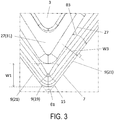
- the top surface 3 of the present embodiment includes a first breaker protrusion 27 and a second breaker protrusion 29.
- the first breaker protrusion 27 and the second breaker protrusion 29 are each separated from the top cutting edges 9.
- the first breaker protrusion 27 and the second breaker protrusion 29 each have the role of curling chips that have advanced thereto.
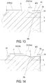
- first breaker protrusion 27 and the second breaker protrusion 29 include inclined surfaces 27a and 29a, respectively, that are inclined with ascending as a distance from the top cutting edges 9 increases. Additionally, bottom ends of these inclined surfaces 27a and 29a constitute the outer edges of the first breaker protrusion 27 and the second breaker protrusion 29.
- an angle formed in a cross-section orthogonal to the top cutting edge 9 between an imaginary plane S orthogonal to the central axis O1 and the inclined surface 27a constitutes an angle of inclination ⁇ 5 of the inclined surface 27a.
- an angle formed in a cross-section orthogonal to the top cutting edge 9 between the imaginary plane S orthogonal to the central axis O1 and the inclined surface 29a constitutes an angle of inclination ⁇ 6 of the inclined surface 29a.
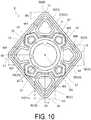
- the first breaker protrusion 27 and the second breaker protrusion 29 are each provided with a flat surface. Specifically, the first breaker protrusion 27 is provided with a flat first surface 31 on an upper end thereof. The second breaker protrusion 29 is provided with a flat second surface 33 on an upper end thereof. In cases where the top surface 3 is used as the seat in the holder, the first surface 31 and the second surface 33 function as surfaces that contact the holder. As such, the first surface 31 and the second surface 33 are positioned on the same plane.
- each of the first surface 31 and the second surface 33 is parallel with respect to the imaginary plane S orthogonal to the height direction. Additionally, a height from the imaginary plane S of each of the first surface 31 and the second surface 33 is uniform. Note that, the "height direction" mentioned above is a direction passing through the center of the top surface 3 and the center of the bottom surface 5 and, in the insert 1 of the present embodiment, matches the extending direction of the central axis O1 of the through-hole 13.
- the bottom surface 5 of the insert 1 of the present embodiment has protrusions of the same configuration as the first breaker protrusion 27 and the second breaker protrusion 29 of the top surface 3.
- a gap W1 between the first breaker protrusion 27 and the first corner cutting edge 19 is larger than a gap W2 between the second breaker protrusion 29 and the second corner cutting edge 23.
- the insert 1 can be seated in the holder at a location close to directly beneath the second corner cutting edge 23. Accordingly, the insert 1 can be stably secured in the holder.
- the thickness of the chips becomes thicker and less prone to deformation. As a result, it is necessary to secure a broad space for curling the chips.
- the gap W1 between the first breaker protrusion 27 and the first corner cutting edge 19 is secured and relatively large. As such, the possibility of the chips jamming in the vicinity of the first corner cutting edge 19 can be reduced.
- a gap W3 between the first breaker protrusion 27 and the first major cutting edge 21 becomes larger as a distance from the first corner cutting edge 19 increases.
- the possibility of the chips jamming in the vicinity of the first corner cutting edge 19 can be further reduced.
- the gap W3 between the first breaker protrusion 27 and the first major cutting edge 21 has the configuration described above, the chips will advance easily in a direction away from a bisecting line of the first corner cutting edge 19. As such, the possibility of the chips jamming in the vicinity of the first corner cutting edge 19 can be reduced.
- a gap W4 between the second breaker protrusion 29 and the second major cutting edge 25 becomes smaller as a distance from the second corner cutting edge 23 increases. As such, the possibility of the chips jamming can be further reduced. Specifically, in cases where machining is performed using the second corner cutting edge 23, the thickness of the chips is thin and, therefore, the flow of the chips is prone to becoming unstable.
- the gap W4 between the second breaker protrusion 29 and the second major cutting edge 25 has the configuration described above, the chips will advance easily in a direction toward a bisecting line of the second corner cutting edge 23. As such, it will be easier to divide the chips at an appropriate length. As a result, the possibility of the chips jamming can be reduced.
- good machining can be performed in cases where machining is performed using either of the first corner portion 15 with an acute angle and the second corner portion 17 with an obtuse angle.
- the gaps between the breaker protrusions and the cutting edges refer to distances between outer edges of the breaker protrusions and the cutting edges when viewing the insert 1 from directly above.
- the lower ends of the breaker protrusions partially constitute the outer peripheral edge of the breaker protrusions.
- the distances between the lower ends of the breaker protrusions and the cutting edges correspond to the gaps between the breaker protrusions and the cutting edges.
- the first major cutting edge 21 has a linear shape. Additionally, the lower end of the first breaker protrusion 27 has a linear shaped portion in a region facing the first major cutting edge 21. As such, when this portion is viewed from directly above, the gap W3 between the first breaker protrusion 27 and the first major cutting edge 21 becomes larger at a constant ratio as a distance from the first corner cutting edge 19 increases.
- the linear shaped portion described above of the lower end of the first breaker protrusion 27 is inclined with respect to the first major cutting edge 21 at the constant a1.
- the area of the first surface 31 can be widely maintained and, at the same time, space can be secured for allowing the chips produced by the first corner cutting edge 19 to flow well.
- an imaginary line formed by extending the linear shaped portion of the outer edge of the first breaker protrusion 27 described above and an imaginary line formed by extending the first major cutting edge 21 intersect at an angle ⁇ 3.
- the second major cutting edge 25 has a linear shape. Additionally, the lower end of the second breaker protrusion 29 has a linear shaped portion in a region facing the second major cutting edge 25. As such, when this portion is viewed from directly above, the gap W4 between the second breaker protrusion 29 and the second major cutting edge 25 becomes smaller at a constant ratio as a distance from the second corner cutting edge 23 increases.
- the linear shaped portion described above of the lower end of the second breaker protrusion 29 is inclined with respect to the second major cutting edge 25 at the constant a2.
- an imaginary line formed by extending the linear shaped portion of the outer edge of the second breaker protrusion 29 described above and an imaginary line formed by extending the second major cutting edge 25 intersect at an angle ⁇ 4.
- the angle ⁇ 3 formed by the outer edge of the first breaker protrusion 27 and the first major cutting edge 21 is larger than the angle ⁇ 4 formed by the outer edge of the second breaker protrusion 29 and the second major cutting edge 25. That is, the angle ⁇ 3 is larger than the angle ⁇ 4.
- the bottom surface 5 has the same configuration as the top surface 3 and the gap W1 is larger than the gap W2.
- the angle ⁇ 4 it is easier to bring the second corner cutting edge 23 closer to the second breaker protrusion 29 by configuring the angle ⁇ 4 to be relatively smaller. As a result, the gap W2 easily becomes smaller.
- a minimum value of the gap W3 between the first breaker protrusion 27 and the first major cutting edge 21 is greater than a minimum value of the gap W4 between the second breaker protrusion 29 and the second major cutting edge 25.
- the broad space for curling the chips can be secured by positioning the first breaker protrusion 27 and the second breaker protrusion 29 as described above.
- the top surface 3 in the present embodiment has a rake surface 35 provided along the top cutting edge 9.
- the rake surface 35 has a role of raking the chips that are cut by the top cutting edge 9.
- the chips of the work material flow over a surface of the rake surface 35.
- the rake surface 35 is inclined with a height from the bottom surface 5 being uniform or decreasing as a distance of the rake surface 35 from the top cutting edge 9 increases.
- the rake surface 35 is inclined with a distance to the bottom surface 5 decreasing as a distance to the through-hole 13 decreases.
- a rake angle which is the angle representing this inclination, is indicated by a maximum value of an angle formed by the rake surface 35 and a virtual plane S orthogonal to the central axis O1 in a cross section orthogonal to the top cutting edge 9.
- the rake surface 35 has a linear shape in the cross section parallel to the central axis O1.
- the insert 1 of the present embodiment includes a first rake surface 35a and a second rake surface 35b as the rake surface 35.
- the first rake surface 35a is located between the first breaker protrusion 27 and the first major cutting edge 21.
- the second rake surface 35b is located between the second breaker protrusion 29 and the second major cutting edge 25.
- a rake angle ⁇ 7 of the first rake surface 35a and a rake angle ⁇ 8 of the second rake surface 35b are the same.
- the top surface 3 of the present embodiment is a surface that includes the first breaker protrusion 27, the second breaker protrusion 29, the rake surface 35, and other components.
- an insert 1 of the present embodiment includes a top surface 3, a bottom surface 5, side surfaces 7, top cutting edges 9, bottom cutting edges 11, and a through-hole 13, the same as in the insert of the first embodiment.
- Examples of the material of the insert 1 include cemented carbide alloy, cermet, or the like.
- the top surface 3 of the present embodiment includes a first breaker protrusion 27, a second breaker protrusion 29, and a rake surface 35.
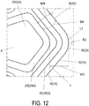
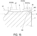
- the insert 1 of the present embodiment also includes a third breaker protrusion 37.
- the third breaker protrusion 37 is located between the first breaker protrusion 27 and the second breaker protrusion 29, and protrudes toward an edge of the top surface 3.
- the possibility of the other cutting edge being damaged can be reduced.
- the third breaker protrusion 37 serves as a barrier to the chip.
- the possibility of the second corner cutting edge 23 becoming damaged is reduced.
- the third breaker protrusion 37 serves as a barrier to the chip.
- a minimum value of a gap W5 between the third breaker protrusion 37 and the edge of the top surface is less than a minimum value of a gap W3 between the first breaker protrusion 27 and the first major cutting edge 21, and also less than a minimum value of a gap W4 between the second breaker protrusion 29 and the second major cutting edge 25.
- the chip can be more stably prevented from advancing in the third breaker protrusion 37.
- the third breaker protrusion 37 protrude up to the rake surface 35, as in the present embodiment.
- the third breaker protrusion 37 includes an inclined surface 37a inclined with ascending as a distance from the top cutting edge 9 increases.
- an angle of inclination ⁇ 9 of the inclined surface 37a in the third breaker protrusion 37 that is, a maximum value of a rise angle ⁇ 9 is greater than an angle of inclination ⁇ 5 of the inclined surface in the first breaker protrusion 27, that is, a maximum value of a rise angle ⁇ 5, and is also greater than an angle of inclination ⁇ 6 of the inclined surface in the second breaker protrusion 29, that is, a maximum value of a rise angle ⁇ 6.
- the chip that has advanced toward the third breaker protrusion 37 may easily overcome the third breaker protrusion 37.
- the maximum value of the rise angle of the third breaker protrusion 37 being configured to be a relatively large value, it may be difficult for the chip to overcome the third breaker protrusion 37. As such, the chip can be more stably prevented from advancing in the third breaker protrusion 37.
- angle of inclination ⁇ 9 of the inclined surface 37a is indicated by an angle formed by the inclined surface 37a and a virtual plane S orthogonal to the central axis O1 in a cross section orthogonal to the top cutting edge 9.
- the third breaker protrusion 37 is provided with a flat third surface 39 on an upper end thereof.
- the third surface 39 functions as a surface that contacts the holder.
- the third surface 39 is positioned on the same plane as the first surface 31 and the second surface 33.
- the cutting tool 101 in the present embodiment is provided with a holder 105 and the above-described cutting insert 1.
- the holder 105 includes an insert pocket 103 on a side of a front end.
- the cutting insert 1 is configured to be mounted to the insert pocket 103 with the top cutting edge or the bottom cutting edge protruding from the front end of the holder 105, as illustrated in FIG. 16 .
- the insert 1 is mounted, in the cutting tool 101 of the present embodiment, with the first corner cutting edge 19 protruding from the front end of the holder 105.
- the holder 105 forms a long and slender rod shape. Also, the front end side of the holder 105 is provided with one insert pocket 103.
- the insert pocket 103 is a portion to which the insert is mounted, and is opened to a front end surface of the holder 105. Here, the insert pocket 103 is also opened to a side surface of the holder 105, making it possible to easily mount the insert 1.
- the insert pocket 103 includes a seating face and a binding side face.
- the seating face is parallel to a bottom surface of the holder 105.
- the binding side face is inclined with respect to the seating face.
- the insert 1 is configured to be mounted to the insert pocket 103.
- the insert 1 is mounted with the top cutting edge or the bottom cutting edge protruding to the front end side of the holder 105.
- the insert 1 is mounted to the holder 105 using a fixing screw 107.
- the insert 1 is mounted to the holder 105 by inserting the fixing screw 107 into a through-hole in the insert 1, inserting a tip of this fixing screw 107 into a screw hole formed in the insert pocket 103, and screwing thread portions thereof.
- the holder 105 it is possible to use steel, cast iron, or the like. In particular, it is preferable to use steel with a high toughness in these members.
- the machined product is manufactured by machining a work material 201.
- the method for manufacturing a machined product in the present embodiment includes the following steps. Specifically the steps of:
- FIG. 17A the work material 201 is rotated about an axis O2, and the cutting tool 101 is brought relatively close to the work material 201.
- FIG. 17B the top cutting edge 9 of the cutting tool 101 is brought into contact with the work material 201, and the work material 201 is cut.
- FIG. 17C the cutting tool 101 is relatively moved away from the work material 201.
- the cutting tool 101 is brought close to the work material 201 by moving the cutting tool 101 in the X1 direction in a state where the axis O2 is fixed and the work material 201 is rotating. Furthermore, in FIG. 17B , the work material 201 is cut by bringing the top cutting edge 9 of the cutting insert into contact with the work material 201 that is rotating. Furthermore, in FIG. 17C , the cutting tool 101 is moved away from the work material 201 by moving the cutting tool 101 in the X2 direction in a state where the work material 201 is rotating.
- the cutting tool 101 is brought into contact with or separated from the work material 201 by moving the cutting tool 101.
- step (1) the work material 201 may be brought close to the cutting tool 101.
- step (3) the work material 201 may be moved away from the cutting tool 101.
- steps of bringing the top cutting edge 9 of the cutting insert 1 into contact with different positions of the work material 201 may be repeated by maintaining the rotating state of the cutting tool 201.
- representative examples of the material of the work material 201 include carbon steel, alloy steel, stainless steel, cast iron, non-ferrous metals, or the like.
Landscapes
- Engineering & Computer Science (AREA)
- Mechanical Engineering (AREA)
- Cutting Tools, Boring Holders, And Turrets (AREA)
- Milling Processes (AREA)
Claims (10)
- Un insert de coupe (1), comportant :une surface supérieure (3) présentant une forme polygonale en vue de dessus, et comprenant une première partie de coin (15) avec un angle aigu (θ1) et une deuxième partie de coin (17) avec un angle obtus (θ2),une surface inférieure (5),une surface latérale (7) située entre la surface supérieure (3) et la surface inférieure (5), etun bord de coupe supérieur (9) disposé le long d'une ligne de crête à une intersection entre la surface supérieure (3) et la surface latérale (7), et comprenant :un premier bord de coupe de coin (19) situé dans la première partie de coin (15),un premier bord de coupe principal (21) adjacent au premier bord de coupe de coin (19),un deuxième bord de coupe de coin (23) situé dans la deuxième partie de coin (17), etun deuxième bord de coupe principal (25) adjacent au deuxième bord de coupe de coin (23),dans lequel la surface supérieure (3) comprend en outre :une première saillie de rupture (27) faisant saillie vers la première partie de coin (15),et une deuxième saillie de rupture (29) faisant saillie vers la deuxième partie de coin (17),dans lequel un écart (W3) entre la première saillie de rupture (27) et le premier bord de coupe principal (21) devient plus grand à mesure qu'une distance depuis le premier bord de coupe de coin (19) augmente, et un écart (W4) entre la deuxième saillie de rupture (29) et le deuxième bord de coupe principal (25) devient plus petit à mesure qu'une distance depuis le deuxième bord de coupe de coin (23) augmente en vue de dessus, caractérisé en ce queun écart (W1) entre la première saillie de rupture (27) et le premier bord de coupe de coin (19) est supérieur à un écart (W2) entre la deuxième saillie de rupture (29) et le deuxième bord de coupe de coin (23) en vue de dessus.
- L'insert de coupe selon la revendication 1, dans lequell'écart (W3) entre la première saillie de rupture et le premier bord de coupe principal devient plus grand selon une proportion constante à mesure qu'une distance depuis le premier bord de coupe de coin augmente, et l'écart (W4) entre la deuxième saillie de rupture et le deuxième bord de coupe principal devient plus petit selon une proportion constante à mesure qu'une distance depuis le deuxième bord de coupe de coin augmente en une vue de dessus.
- L'insert de coupe selon la revendication 2, dans lequelun angle (θ3) formé par un bord supérieur de la première saillie de rupture et le premier bord de coupe principal est supérieur à un angle (θ4) formé par un bord extérieur de la deuxième saillie de rupture et le deuxième bord de coupe principal en vue de dessus.
- L'insert de coupe selon l'une quelconque des revendications 1 à 3, dans lequelune valeur minimale de l'écart (W3) entre la première saillie de rupture et le premier bord de coupe principal est supérieure à une valeur minimale de l'écart (W4) entre la deuxième saillie de rupture et le deuxième bord de coupe principal en vue de dessus.
- L'insert de coupe selon l'une quelconque des revendications 1 à 4, dans lequella surface supérieure comprend :une première face de coupe située entre la première saillie de rupture et le premier bord de coupe principal, etune deuxième face de coupe située entre la deuxième saillie de rupture et le deuxième bord de coupe principal, dans laquelle un angle de coupe (θ7) de la première face de coupe est égal à un angle de coupe (θ8) de la deuxième face de coupe.
- L'insert de coupe selon l'une quelconque des revendications 1 à 5, dans lequel :la surface supérieure comprend en outre une troisième saillie de rupture située entre la première saillie de rupture et la deuxième saillie de rupture et faisant saillie vers un bord de la surface supérieure.
- L'insert de coupe selon la revendication 6, dans lequel :une valeur minimale d'un écart (W5) entre la troisième saillie de rupture et le bord de la surface supérieure est inférieure à la valeur minimale de l'écart (W3) entre la première saillie de rupture et le premier bord de coupe principal, et est inférieure à la valeur minimale de l'écart (W4) entre la deuxième saillie de rupture et le deuxième bord de coupe principal en vue de dessus.
- L'insert de coupe selon la revendication 6 ou 7, dans lequel :une valeur maximale d'an angle de pente (θ9) de la troisième saillie de rupture est supérieure à une valeur maximale d'un angle de pente (θ5) de la première saillie de rupture, et est supérieure à une valeur maximale d'un angle de pente (θ6) de la deuxième saillie de rupture.
- Un outil de coupe, comportant :un support comprenant une poche d'insert sur un côté d'une extrémité avant de celui-ci, etl'insert de coupe selon l'une quelconque des revendications 1 à 8, configuré pour être monté à la poche d'insert avec le bord de coupe supérieur faisant saillie depuis l'extrémité avant du support.
- Un procédé de production d'un produit usiné, le procédé comprenant les étapes suivantes consistant à :faire tourner un matériel de travail,mettre le bord de coupe supérieur de l'outil de coupe selon la revendication 9 en contact avec le matériel de travail qui est tourné, etséparer l'outil de coupe du matériel de travail.
Applications Claiming Priority (2)
| Application Number | Priority Date | Filing Date | Title |
|---|---|---|---|
| JP2014065293 | 2014-03-27 | ||
| PCT/JP2015/059480 WO2015147214A1 (fr) | 2014-03-27 | 2015-03-26 | Plaquette de coupe, outil de coupe, et procédé pour fabriquer une pièce de coupe |
Publications (3)
| Publication Number | Publication Date |
|---|---|
| EP3124148A1 EP3124148A1 (fr) | 2017-02-01 |
| EP3124148A4 EP3124148A4 (fr) | 2017-11-22 |
| EP3124148B1 true EP3124148B1 (fr) | 2019-02-27 |
Family
ID=54195718
Family Applications (1)
| Application Number | Title | Priority Date | Filing Date |
|---|---|---|---|
| EP15768168.5A Active EP3124148B1 (fr) | 2014-03-27 | 2015-03-26 | Plaquette de coupe, outil de coupe, et procédé pour fabriquer un produit machiné |
Country Status (5)
| Country | Link |
|---|---|
| US (1) | US10166606B2 (fr) |
| EP (1) | EP3124148B1 (fr) |
| JP (1) | JP6190039B2 (fr) |
| CN (1) | CN106132605B (fr) |
| WO (1) | WO2015147214A1 (fr) |
Families Citing this family (10)
| Publication number | Priority date | Publication date | Assignee | Title |
|---|---|---|---|---|
| DE112017003869B4 (de) | 2016-08-03 | 2024-05-29 | Kyocera Corporation | Schneideinsatz, Schneidwerkzeug und Verfahren des Herstellens eines maschinell-bearbeiteten Produkts |
| CN110198800B (zh) * | 2017-01-30 | 2020-11-27 | 京瓷株式会社 | 切削刀片、钻头及使用该钻头的切削加工物的制造方法 |
| JP6708183B2 (ja) * | 2017-08-10 | 2020-06-10 | 株式会社タンガロイ | 切削インサート及び切削工具 |
| KR102386942B1 (ko) | 2017-08-23 | 2022-04-14 | 대구텍 유한책임회사 | 드릴용 절삭 인서트 |
| JP7168655B2 (ja) * | 2018-03-27 | 2022-11-09 | 京セラ株式会社 | 切削インサート、切削工具及び切削加工物の製造方法 |
| WO2019227319A1 (fr) * | 2018-05-29 | 2019-12-05 | 南通纺织丝绸产业技术研究院 | Film de polycaprolactone contenant du fluor et son procédé de préparation |
| DE112019003627T5 (de) * | 2018-07-18 | 2021-04-01 | Kyocera Corporation | Schneideinsatz, schneidwerkzeug und verfahren zur herstellung eines maschinell bearbeiteten produkts |
| CN109014258A (zh) * | 2018-09-10 | 2018-12-18 | 株洲华锐精密工具股份有限公司 | 一种用于钛合金半精加工的可转位车刀片 |
| CN113316494B (zh) * | 2019-10-16 | 2023-07-25 | 住友电工硬质合金株式会社 | 切削刀具 |
| CN114650892B (zh) * | 2019-11-13 | 2024-06-21 | 京瓷株式会社 | 切削刀片、切削工具以及切削加工物的制造方法 |
Family Cites Families (20)
| Publication number | Priority date | Publication date | Assignee | Title |
|---|---|---|---|---|
| US5141367A (en) * | 1990-12-18 | 1992-08-25 | Kennametal, Inc. | Ceramic cutting tool with chip control |
| JPH05177416A (ja) * | 1992-01-07 | 1993-07-20 | Gte Valenite Corp | チップ制御型切断刃インサート |
| SE509362C2 (sv) * | 1994-03-18 | 1999-01-18 | Sandvik Ab | Diamantbelagd kropp |
| DE19901456B4 (de) * | 1998-01-19 | 2009-07-09 | Mitsubishi Materials Corp. | Wendeschneidplatte |
| JP3812473B2 (ja) * | 2001-11-20 | 2006-08-23 | 三菱マテリアル株式会社 | スローアウェイチップ |
| JP4654962B2 (ja) * | 2001-11-20 | 2011-03-23 | 三菱マテリアル株式会社 | スローアウェイチップ |
| AT8433U1 (de) * | 2005-03-11 | 2006-08-15 | Ceratizit Austria Gmbh | Wendeschneidplatte |
| JP5028757B2 (ja) | 2005-06-28 | 2012-09-19 | 株式会社タンガロイ | スローアウェイチップ |
| JP4967721B2 (ja) * | 2007-03-07 | 2012-07-04 | 三菱マテリアル株式会社 | 切削インサート |
| DE112008002261B4 (de) * | 2007-08-31 | 2015-06-25 | Kyocera Corporation | Schneideinsatz, Schneidwerkzeug und Schneidverfahren |
| DE102008019955A1 (de) * | 2008-04-21 | 2009-10-22 | Kennametal Inc. | Werkzeughalter |
| JP2010042462A (ja) | 2008-08-11 | 2010-02-25 | Sumitomo Electric Hardmetal Corp | 旋削用チップ |
| AT11676U1 (de) * | 2009-10-02 | 2011-03-15 | Ceratizit Austria Gmbh | Schneideinsatz für ein schneidwerkzeug |
| KR101067156B1 (ko) * | 2009-12-07 | 2011-09-22 | 대구텍 유한회사 | 다기능 절삭 공구 및 그를 위한 공구 홀더 |
| CN201579436U (zh) * | 2009-12-28 | 2010-09-15 | 中硬金属切削(大连)有限公司 | 一种半精加工的双面槽型可转位数控车削刀片 |
| CN102844139B (zh) * | 2010-06-30 | 2013-10-16 | 京瓷株式会社 | 镶刀及切削工具、以及使用该切削工具的切削加工物的制造方法 |
| SE535166C2 (sv) * | 2010-08-25 | 2012-05-08 | Sandvik Intellectual Property | Dubbelsidigt, indexerbart svarvskär med spetsig spånvinkel |
| US8967920B2 (en) * | 2011-09-13 | 2015-03-03 | Iscar, Ltd. | Cutting insert and chip-control arrangement therefor |
| SE536295C2 (sv) * | 2011-09-23 | 2013-08-06 | Sandvik Intellectual Property | Månghörnigt svarvskär med förbättrad spånkontroll |
| DE102014102800A1 (de) * | 2013-03-04 | 2014-09-04 | Kennametal India Limited | Schneideinsatz mit assymetrischem Spanformer |
-
2015
- 2015-03-26 CN CN201580015387.0A patent/CN106132605B/zh active Active
- 2015-03-26 JP JP2016510507A patent/JP6190039B2/ja active Active
- 2015-03-26 EP EP15768168.5A patent/EP3124148B1/fr active Active
- 2015-03-26 WO PCT/JP2015/059480 patent/WO2015147214A1/fr not_active Ceased
- 2015-03-26 US US15/129,093 patent/US10166606B2/en active Active
Non-Patent Citations (1)
| Title |
|---|
| None * |
Also Published As
| Publication number | Publication date |
|---|---|
| WO2015147214A1 (fr) | 2015-10-01 |
| US10166606B2 (en) | 2019-01-01 |
| JPWO2015147214A1 (ja) | 2017-04-13 |
| US20170120342A1 (en) | 2017-05-04 |
| CN106132605B (zh) | 2018-04-06 |
| JP6190039B2 (ja) | 2017-08-30 |
| EP3124148A1 (fr) | 2017-02-01 |
| CN106132605A (zh) | 2016-11-16 |
| EP3124148A4 (fr) | 2017-11-22 |
Similar Documents
| Publication | Publication Date | Title |
|---|---|---|
| EP3124148B1 (fr) | Plaquette de coupe, outil de coupe, et procédé pour fabriquer un produit machiné | |
| EP3822011B1 (fr) | Insert de coupe, outil de coupe et procédé de fabrication d'un produit usiné | |
| US10099294B2 (en) | Cutting insert, cutting tool, and method for manufacturing machined product | |
| JP6356781B2 (ja) | 切削インサート、切削工具及び切削加工物の製造方法 | |
| EP2962795B1 (fr) | Plaquette de coupe, outil de coupe et procédé de fabrication d'une pièce de travail coupée | |
| EP3195962B1 (fr) | Plaquette de coupe, outil de coupe et procédé de fabrication pour objet coupé | |
| US20150075338A1 (en) | Cutting insert, cutting tool, and method of manufacturing machined product | |
| US10124426B2 (en) | Cutting insert, cutting tool, and method of manufacturing machined product | |
| US11027339B2 (en) | Cutting insert, cutting tool, and method of manufacturing machined product | |
| US20150165532A1 (en) | Cutting insert, cutting tool, and method of producing machined product | |
| US20150158089A1 (en) | Cutting insert, cutting tool, and method of producing machined product using them | |
| US10239125B2 (en) | Cutting insert, cutting tool, and method for manufacturing machined product using same | |
| US20190084060A1 (en) | Cutting insert, cutting tool, and method for manufacturing a cut workpiece | |
| EP3124143B1 (fr) | Plaquette de coupe, outil de coupe et procédé de fabrication de produit coupé | |
| US10576547B2 (en) | Cutting insert, cutting tool, and method for manufacturing machined product | |
| JP6462126B2 (ja) | 切削インサート、切削工具及びこれを用いた切削加工物の製造方法 | |
| WO2018021419A1 (fr) | Plaquette de coupe, outil de coupe et procédé de fabrication de pièce par découpe | |
| US11305358B2 (en) | Cutting insert, cutting tool, and method for manufacturing machined product | |
| CN114025902B (zh) | 切削刀片、切削刀具以及切削加工物的制造方法 | |
| JP6877921B2 (ja) | 切削インサート、切削工具及び切削加工物の製造方法 | |
| US20250222528A1 (en) | Cutting insert, cutting tool, and method for manufacturing machined product | |
| US11628504B2 (en) | Cutting insert, cutting tool, and method for manufacturing machined product |
Legal Events
| Date | Code | Title | Description |
|---|---|---|---|
| STAA | Information on the status of an ep patent application or granted ep patent |
Free format text: STATUS: THE INTERNATIONAL PUBLICATION HAS BEEN MADE |
|
| PUAI | Public reference made under article 153(3) epc to a published international application that has entered the european phase |
Free format text: ORIGINAL CODE: 0009012 |
|
| STAA | Information on the status of an ep patent application or granted ep patent |
Free format text: STATUS: REQUEST FOR EXAMINATION WAS MADE |
|
| 17P | Request for examination filed |
Effective date: 20160922 |
|
| AK | Designated contracting states |
Kind code of ref document: A1 Designated state(s): AL AT BE BG CH CY CZ DE DK EE ES FI FR GB GR HR HU IE IS IT LI LT LU LV MC MK MT NL NO PL PT RO RS SE SI SK SM TR |
|
| AX | Request for extension of the european patent |
Extension state: BA ME |
|
| DAV | Request for validation of the european patent (deleted) | ||
| DAX | Request for extension of the european patent (deleted) | ||
| REG | Reference to a national code |
Ref country code: DE Ref legal event code: R079 Ref document number: 602015025457 Country of ref document: DE Free format text: PREVIOUS MAIN CLASS: B23B0027220000 Ipc: B23B0027140000 |
|
| A4 | Supplementary search report drawn up and despatched |
Effective date: 20171020 |
|
| RIC1 | Information provided on ipc code assigned before grant |
Ipc: B23B 27/22 20060101ALI20171016BHEP Ipc: B23B 27/14 20060101AFI20171016BHEP |
|
| GRAP | Despatch of communication of intention to grant a patent |
Free format text: ORIGINAL CODE: EPIDOSNIGR1 |
|
| STAA | Information on the status of an ep patent application or granted ep patent |
Free format text: STATUS: GRANT OF PATENT IS INTENDED |
|
| INTG | Intention to grant announced |
Effective date: 20180911 |
|
| GRAS | Grant fee paid |
Free format text: ORIGINAL CODE: EPIDOSNIGR3 |
|
| GRAA | (expected) grant |
Free format text: ORIGINAL CODE: 0009210 |
|
| STAA | Information on the status of an ep patent application or granted ep patent |
Free format text: STATUS: THE PATENT HAS BEEN GRANTED |
|
| AK | Designated contracting states |
Kind code of ref document: B1 Designated state(s): AL AT BE BG CH CY CZ DE DK EE ES FI FR GB GR HR HU IE IS IT LI LT LU LV MC MK MT NL NO PL PT RO RS SE SI SK SM TR |
|
| REG | Reference to a national code |
Ref country code: GB Ref legal event code: FG4D |
|
| REG | Reference to a national code |
Ref country code: CH Ref legal event code: EP |
|
| REG | Reference to a national code |
Ref country code: AT Ref legal event code: REF Ref document number: 1100605 Country of ref document: AT Kind code of ref document: T Effective date: 20190315 |
|
| REG | Reference to a national code |
Ref country code: IE Ref legal event code: FG4D |
|
| REG | Reference to a national code |
Ref country code: DE Ref legal event code: R096 Ref document number: 602015025457 Country of ref document: DE |
|
| REG | Reference to a national code |
Ref country code: NL Ref legal event code: MP Effective date: 20190227 |
|
| REG | Reference to a national code |
Ref country code: LT Ref legal event code: MG4D |
|
| PG25 | Lapsed in a contracting state [announced via postgrant information from national office to epo] |
Ref country code: NO Free format text: LAPSE BECAUSE OF FAILURE TO SUBMIT A TRANSLATION OF THE DESCRIPTION OR TO PAY THE FEE WITHIN THE PRESCRIBED TIME-LIMIT Effective date: 20190527 Ref country code: PT Free format text: LAPSE BECAUSE OF FAILURE TO SUBMIT A TRANSLATION OF THE DESCRIPTION OR TO PAY THE FEE WITHIN THE PRESCRIBED TIME-LIMIT Effective date: 20190627 Ref country code: FI Free format text: LAPSE BECAUSE OF FAILURE TO SUBMIT A TRANSLATION OF THE DESCRIPTION OR TO PAY THE FEE WITHIN THE PRESCRIBED TIME-LIMIT Effective date: 20190227 Ref country code: SE Free format text: LAPSE BECAUSE OF FAILURE TO SUBMIT A TRANSLATION OF THE DESCRIPTION OR TO PAY THE FEE WITHIN THE PRESCRIBED TIME-LIMIT Effective date: 20190227 Ref country code: LT Free format text: LAPSE BECAUSE OF FAILURE TO SUBMIT A TRANSLATION OF THE DESCRIPTION OR TO PAY THE FEE WITHIN THE PRESCRIBED TIME-LIMIT Effective date: 20190227 |
|
| PG25 | Lapsed in a contracting state [announced via postgrant information from national office to epo] |
Ref country code: RS Free format text: LAPSE BECAUSE OF FAILURE TO SUBMIT A TRANSLATION OF THE DESCRIPTION OR TO PAY THE FEE WITHIN THE PRESCRIBED TIME-LIMIT Effective date: 20190227 Ref country code: HR Free format text: LAPSE BECAUSE OF FAILURE TO SUBMIT A TRANSLATION OF THE DESCRIPTION OR TO PAY THE FEE WITHIN THE PRESCRIBED TIME-LIMIT Effective date: 20190227 Ref country code: LV Free format text: LAPSE BECAUSE OF FAILURE TO SUBMIT A TRANSLATION OF THE DESCRIPTION OR TO PAY THE FEE WITHIN THE PRESCRIBED TIME-LIMIT Effective date: 20190227 Ref country code: GR Free format text: LAPSE BECAUSE OF FAILURE TO SUBMIT A TRANSLATION OF THE DESCRIPTION OR TO PAY THE FEE WITHIN THE PRESCRIBED TIME-LIMIT Effective date: 20190528 Ref country code: NL Free format text: LAPSE BECAUSE OF FAILURE TO SUBMIT A TRANSLATION OF THE DESCRIPTION OR TO PAY THE FEE WITHIN THE PRESCRIBED TIME-LIMIT Effective date: 20190227 Ref country code: IS Free format text: LAPSE BECAUSE OF FAILURE TO SUBMIT A TRANSLATION OF THE DESCRIPTION OR TO PAY THE FEE WITHIN THE PRESCRIBED TIME-LIMIT Effective date: 20190627 Ref country code: BG Free format text: LAPSE BECAUSE OF FAILURE TO SUBMIT A TRANSLATION OF THE DESCRIPTION OR TO PAY THE FEE WITHIN THE PRESCRIBED TIME-LIMIT Effective date: 20190527 |
|
| REG | Reference to a national code |
Ref country code: AT Ref legal event code: MK05 Ref document number: 1100605 Country of ref document: AT Kind code of ref document: T Effective date: 20190227 |
|
| PG25 | Lapsed in a contracting state [announced via postgrant information from national office to epo] |
Ref country code: IT Free format text: LAPSE BECAUSE OF FAILURE TO SUBMIT A TRANSLATION OF THE DESCRIPTION OR TO PAY THE FEE WITHIN THE PRESCRIBED TIME-LIMIT Effective date: 20190227 Ref country code: RO Free format text: LAPSE BECAUSE OF FAILURE TO SUBMIT A TRANSLATION OF THE DESCRIPTION OR TO PAY THE FEE WITHIN THE PRESCRIBED TIME-LIMIT Effective date: 20190227 Ref country code: DK Free format text: LAPSE BECAUSE OF FAILURE TO SUBMIT A TRANSLATION OF THE DESCRIPTION OR TO PAY THE FEE WITHIN THE PRESCRIBED TIME-LIMIT Effective date: 20190227 Ref country code: EE Free format text: LAPSE BECAUSE OF FAILURE TO SUBMIT A TRANSLATION OF THE DESCRIPTION OR TO PAY THE FEE WITHIN THE PRESCRIBED TIME-LIMIT Effective date: 20190227 Ref country code: AL Free format text: LAPSE BECAUSE OF FAILURE TO SUBMIT A TRANSLATION OF THE DESCRIPTION OR TO PAY THE FEE WITHIN THE PRESCRIBED TIME-LIMIT Effective date: 20190227 Ref country code: ES Free format text: LAPSE BECAUSE OF FAILURE TO SUBMIT A TRANSLATION OF THE DESCRIPTION OR TO PAY THE FEE WITHIN THE PRESCRIBED TIME-LIMIT Effective date: 20190227 Ref country code: CZ Free format text: LAPSE BECAUSE OF FAILURE TO SUBMIT A TRANSLATION OF THE DESCRIPTION OR TO PAY THE FEE WITHIN THE PRESCRIBED TIME-LIMIT Effective date: 20190227 Ref country code: SK Free format text: LAPSE BECAUSE OF FAILURE TO SUBMIT A TRANSLATION OF THE DESCRIPTION OR TO PAY THE FEE WITHIN THE PRESCRIBED TIME-LIMIT Effective date: 20190227 |
|
| REG | Reference to a national code |
Ref country code: CH Ref legal event code: PL |
|
| REG | Reference to a national code |
Ref country code: DE Ref legal event code: R097 Ref document number: 602015025457 Country of ref document: DE |
|
| PG25 | Lapsed in a contracting state [announced via postgrant information from national office to epo] |
Ref country code: PL Free format text: LAPSE BECAUSE OF FAILURE TO SUBMIT A TRANSLATION OF THE DESCRIPTION OR TO PAY THE FEE WITHIN THE PRESCRIBED TIME-LIMIT Effective date: 20190227 Ref country code: SM Free format text: LAPSE BECAUSE OF FAILURE TO SUBMIT A TRANSLATION OF THE DESCRIPTION OR TO PAY THE FEE WITHIN THE PRESCRIBED TIME-LIMIT Effective date: 20190227 Ref country code: LU Free format text: LAPSE BECAUSE OF NON-PAYMENT OF DUE FEES Effective date: 20190326 |
|
| REG | Reference to a national code |
Ref country code: BE Ref legal event code: MM Effective date: 20190331 |
|
| PG25 | Lapsed in a contracting state [announced via postgrant information from national office to epo] |
Ref country code: AT Free format text: LAPSE BECAUSE OF FAILURE TO SUBMIT A TRANSLATION OF THE DESCRIPTION OR TO PAY THE FEE WITHIN THE PRESCRIBED TIME-LIMIT Effective date: 20190227 Ref country code: MC Free format text: LAPSE BECAUSE OF FAILURE TO SUBMIT A TRANSLATION OF THE DESCRIPTION OR TO PAY THE FEE WITHIN THE PRESCRIBED TIME-LIMIT Effective date: 20190227 |
|
| PLBE | No opposition filed within time limit |
Free format text: ORIGINAL CODE: 0009261 |
|
| STAA | Information on the status of an ep patent application or granted ep patent |
Free format text: STATUS: NO OPPOSITION FILED WITHIN TIME LIMIT |
|
| GBPC | Gb: european patent ceased through non-payment of renewal fee |
Effective date: 20190527 |
|
| PG25 | Lapsed in a contracting state [announced via postgrant information from national office to epo] |
Ref country code: IE Free format text: LAPSE BECAUSE OF NON-PAYMENT OF DUE FEES Effective date: 20190326 Ref country code: CH Free format text: LAPSE BECAUSE OF NON-PAYMENT OF DUE FEES Effective date: 20190331 Ref country code: LI Free format text: LAPSE BECAUSE OF NON-PAYMENT OF DUE FEES Effective date: 20190331 |
|
| 26N | No opposition filed |
Effective date: 20191128 |
|
| PG25 | Lapsed in a contracting state [announced via postgrant information from national office to epo] |
Ref country code: BE Free format text: LAPSE BECAUSE OF NON-PAYMENT OF DUE FEES Effective date: 20190331 Ref country code: SI Free format text: LAPSE BECAUSE OF FAILURE TO SUBMIT A TRANSLATION OF THE DESCRIPTION OR TO PAY THE FEE WITHIN THE PRESCRIBED TIME-LIMIT Effective date: 20190227 Ref country code: FR Free format text: LAPSE BECAUSE OF NON-PAYMENT OF DUE FEES Effective date: 20190427 |
|
| PG25 | Lapsed in a contracting state [announced via postgrant information from national office to epo] |
Ref country code: TR Free format text: LAPSE BECAUSE OF FAILURE TO SUBMIT A TRANSLATION OF THE DESCRIPTION OR TO PAY THE FEE WITHIN THE PRESCRIBED TIME-LIMIT Effective date: 20190227 |
|
| PG25 | Lapsed in a contracting state [announced via postgrant information from national office to epo] |
Ref country code: GB Free format text: LAPSE BECAUSE OF NON-PAYMENT OF DUE FEES Effective date: 20190527 |
|
| PG25 | Lapsed in a contracting state [announced via postgrant information from national office to epo] |
Ref country code: MT Free format text: LAPSE BECAUSE OF NON-PAYMENT OF DUE FEES Effective date: 20190326 |
|
| PG25 | Lapsed in a contracting state [announced via postgrant information from national office to epo] |
Ref country code: CY Free format text: LAPSE BECAUSE OF FAILURE TO SUBMIT A TRANSLATION OF THE DESCRIPTION OR TO PAY THE FEE WITHIN THE PRESCRIBED TIME-LIMIT Effective date: 20190227 |
|
| PG25 | Lapsed in a contracting state [announced via postgrant information from national office to epo] |
Ref country code: HU Free format text: LAPSE BECAUSE OF FAILURE TO SUBMIT A TRANSLATION OF THE DESCRIPTION OR TO PAY THE FEE WITHIN THE PRESCRIBED TIME-LIMIT; INVALID AB INITIO Effective date: 20150326 |
|
| PG25 | Lapsed in a contracting state [announced via postgrant information from national office to epo] |
Ref country code: MK Free format text: LAPSE BECAUSE OF FAILURE TO SUBMIT A TRANSLATION OF THE DESCRIPTION OR TO PAY THE FEE WITHIN THE PRESCRIBED TIME-LIMIT Effective date: 20190227 |
|
| P01 | Opt-out of the competence of the unified patent court (upc) registered |
Effective date: 20230505 |
|
| PGFP | Annual fee paid to national office [announced via postgrant information from national office to epo] |
Ref country code: DE Payment date: 20260128 Year of fee payment: 12 |