EP3124377B1 - System und verfahren zur elektronischen propellerblattwinkelpositionsrückkopplung - Google Patents
System und verfahren zur elektronischen propellerblattwinkelpositionsrückkopplung Download PDFInfo
- Publication number
- EP3124377B1 EP3124377B1 EP16189338.3A EP16189338A EP3124377B1 EP 3124377 B1 EP3124377 B1 EP 3124377B1 EP 16189338 A EP16189338 A EP 16189338A EP 3124377 B1 EP3124377 B1 EP 3124377B1
- Authority
- EP
- European Patent Office
- Prior art keywords
- singularities
- sensor
- propeller
- singularity
- annular member
- Prior art date
- Legal status (The legal status is an assumption and is not a legal conclusion. Google has not performed a legal analysis and makes no representation as to the accuracy of the status listed.)
- Active
Links
Images

Classifications
-
- B—PERFORMING OPERATIONS; TRANSPORTING
- B64—AIRCRAFT; AVIATION; COSMONAUTICS
- B64C—AEROPLANES; HELICOPTERS
- B64C11/00—Propellers, e.g. of ducted type; Features common to propellers and rotors for rotorcraft
- B64C11/30—Blade pitch-changing mechanisms
- B64C11/301—Blade pitch-changing mechanisms characterised by blade position indicating means
-
- B—PERFORMING OPERATIONS; TRANSPORTING
- B64—AIRCRAFT; AVIATION; COSMONAUTICS
- B64D—EQUIPMENT FOR FITTING IN OR TO AIRCRAFT; FLIGHT SUITS; PARACHUTES; ARRANGEMENT OR MOUNTING OF POWER PLANTS OR PROPULSION TRANSMISSIONS IN AIRCRAFT
- B64D45/00—Aircraft indicators or protectors not otherwise provided for
-
- F—MECHANICAL ENGINEERING; LIGHTING; HEATING; WEAPONS; BLASTING
- F01—MACHINES OR ENGINES IN GENERAL; ENGINE PLANTS IN GENERAL; STEAM ENGINES
- F01D—NON-POSITIVE DISPLACEMENT MACHINES OR ENGINES, e.g. STEAM TURBINES
- F01D7/00—Rotors with blades adjustable in operation; Control thereof
-
- G—PHYSICS
- G01—MEASURING; TESTING
- G01P—MEASURING LINEAR OR ANGULAR SPEED, ACCELERATION, DECELERATION, OR SHOCK; INDICATING PRESENCE, ABSENCE, OR DIRECTION, OF MOVEMENT
- G01P3/00—Measuring linear or angular speed; Measuring differences of linear or angular speeds
- G01P3/42—Devices characterised by the use of electric or magnetic means
- G01P3/44—Devices characterised by the use of electric or magnetic means for measuring angular speed
- G01P3/48—Devices characterised by the use of electric or magnetic means for measuring angular speed by measuring frequency of generated current or voltage
- G01P3/481—Devices characterised by the use of electric or magnetic means for measuring angular speed by measuring frequency of generated current or voltage of pulse signals
- G01P3/487—Devices characterised by the use of electric or magnetic means for measuring angular speed by measuring frequency of generated current or voltage of pulse signals delivered by rotating magnets
-
- G—PHYSICS
- G01—MEASURING; TESTING
- G01P—MEASURING LINEAR OR ANGULAR SPEED, ACCELERATION, DECELERATION, OR SHOCK; INDICATING PRESENCE, ABSENCE, OR DIRECTION, OF MOVEMENT
- G01P3/00—Measuring linear or angular speed; Measuring differences of linear or angular speeds
- G01P3/42—Devices characterised by the use of electric or magnetic means
- G01P3/44—Devices characterised by the use of electric or magnetic means for measuring angular speed
- G01P3/48—Devices characterised by the use of electric or magnetic means for measuring angular speed by measuring frequency of generated current or voltage
- G01P3/481—Devices characterised by the use of electric or magnetic means for measuring angular speed by measuring frequency of generated current or voltage of pulse signals
- G01P3/488—Devices characterised by the use of electric or magnetic means for measuring angular speed by measuring frequency of generated current or voltage of pulse signals delivered by variable reluctance detectors
-
- B—PERFORMING OPERATIONS; TRANSPORTING
- B64—AIRCRAFT; AVIATION; COSMONAUTICS
- B64C—AEROPLANES; HELICOPTERS
- B64C11/00—Propellers, e.g. of ducted type; Features common to propellers and rotors for rotorcraft
- B64C11/02—Hub construction
- B64C11/04—Blade mountings
- B64C11/06—Blade mountings for variable-pitch blades
-
- G—PHYSICS
- G01—MEASURING; TESTING
- G01D—MEASURING NOT SPECIALLY ADAPTED FOR A SPECIFIC VARIABLE; ARRANGEMENTS FOR MEASURING TWO OR MORE VARIABLES NOT COVERED IN A SINGLE OTHER SUBCLASS; TARIFF METERING APPARATUS; MEASURING OR TESTING NOT OTHERWISE PROVIDED FOR
- G01D5/00—Mechanical means for transferring the output of a sensing member; Means for converting the output of a sensing member to another variable where the form or nature of the sensing member does not constrain the means for converting; Transducers not specially adapted for a specific variable
- G01D5/12—Mechanical means for transferring the output of a sensing member; Means for converting the output of a sensing member to another variable where the form or nature of the sensing member does not constrain the means for converting; Transducers not specially adapted for a specific variable using electric or magnetic means
- G01D5/14—Mechanical means for transferring the output of a sensing member; Means for converting the output of a sensing member to another variable where the form or nature of the sensing member does not constrain the means for converting; Transducers not specially adapted for a specific variable using electric or magnetic means influencing the magnitude of a current or voltage
- G01D5/142—Mechanical means for transferring the output of a sensing member; Means for converting the output of a sensing member to another variable where the form or nature of the sensing member does not constrain the means for converting; Transducers not specially adapted for a specific variable using electric or magnetic means influencing the magnitude of a current or voltage using Hall-effect devices
- G01D5/145—Mechanical means for transferring the output of a sensing member; Means for converting the output of a sensing member to another variable where the form or nature of the sensing member does not constrain the means for converting; Transducers not specially adapted for a specific variable using electric or magnetic means influencing the magnitude of a current or voltage using Hall-effect devices influenced by the relative movement between the Hall device and magnetic fields
-
- G—PHYSICS
- G01—MEASURING; TESTING
- G01D—MEASURING NOT SPECIALLY ADAPTED FOR A SPECIFIC VARIABLE; ARRANGEMENTS FOR MEASURING TWO OR MORE VARIABLES NOT COVERED IN A SINGLE OTHER SUBCLASS; TARIFF METERING APPARATUS; MEASURING OR TESTING NOT OTHERWISE PROVIDED FOR
- G01D5/00—Mechanical means for transferring the output of a sensing member; Means for converting the output of a sensing member to another variable where the form or nature of the sensing member does not constrain the means for converting; Transducers not specially adapted for a specific variable
- G01D5/12—Mechanical means for transferring the output of a sensing member; Means for converting the output of a sensing member to another variable where the form or nature of the sensing member does not constrain the means for converting; Transducers not specially adapted for a specific variable using electric or magnetic means
- G01D5/244—Mechanical means for transferring the output of a sensing member; Means for converting the output of a sensing member to another variable where the form or nature of the sensing member does not constrain the means for converting; Transducers not specially adapted for a specific variable using electric or magnetic means influencing characteristics of pulses or pulse trains; generating pulses or pulse trains
- G01D5/245—Mechanical means for transferring the output of a sensing member; Means for converting the output of a sensing member to another variable where the form or nature of the sensing member does not constrain the means for converting; Transducers not specially adapted for a specific variable using electric or magnetic means influencing characteristics of pulses or pulse trains; generating pulses or pulse trains using a variable number of pulses in a train
- G01D5/2451—Incremental encoders
Definitions
- the application relates generally to propeller feedback systems for gas turbine engines and, more particularly, to systems and methods for blade angle position feedback.
- GB 2 465 575 A discloses an aircraft propeller as set forth in the preamble of claim 1.
- GB 2 346 701 A discloses an apparatus for indicating pitch angle of a propeller blade.
- an aircraft propeller as recited in claim 1.
- the invention also provides a method for blade angle position feedback for an aircraft propeller as recited in claim 10.
- the at least one sensor adjacent the annular member, the at least one sensor configured for successively detecting a passage of each one of the at least two first singularities and the at least one second singularity as the annular member is rotated and axially displaced and for generating a sensor signal accordingly.
- the annular member and at least one sensor are configured for relative axial displacement between a first relative axial position and a second relative axial position, the first position corresponding to the first mode of operation and the second position corresponding to the second mode of operation.
- the system also comprises a detection unit connected to the at least one sensor for receiving the sensor signal therefrom, determining on the basis of the sensor signal a time interval elapsed between the passage of successive ones of the at least two first singularities and the at least one second singularity, and computing from the time interval a blade angle position for the plurality of blades.
- a method for blade angle position feedback for an aircraft propeller the propeller rotatable about an axis and comprising a plurality of blades each rotatable through a plurality of blade angles, the propeller having at least a first mode of operation where the plurality of blades are operated at a positive blade angle and a second mode of operation where the plurality of blades are operated at a negative blade angle.
- the method comprises receiving a sensor signal from at least one sensor fixedly mounted adjacent an annular member operatively connected to rotate with the propeller.
- the annular member comprises at least two circumferentially-spaced first singularities extending substantially parallel to the axis and at least one second singularity extending non-parallel to the first singularities.
- the at least one sensor is configured for successively detecting a passage of each one of the at least two first singularities and the at least one second singularity as the annular member is rotated and axially displaced and for generating a sensor signal accordingly.
- the annular member and at least one sensor are configured for relative axial displacement between a first relative axial position and a second relative axial position, the first position corresponding to the first mode of operation and the second position corresponding to the second mode of operation.
- the method further comprises determining on the basis of the sensor signal a time interval elapsed between the passage of successive ones of the at least two first singularities and the at least one second singularity, and computing from the time interval a blade angle position for the plurality of blades.
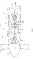
- Fig. 1 illustrates a gas turbine engine 10, of a type typically provided for use in subsonic flight, comprising an inlet 12, through which ambient air is propelled, a compressor section 14 for pressurizing the air, a combustor 16 in which the compressed air is mixed with fuel and ignited for generating an annular stream of hot combustion gases, and a turbine section 18 for extracting energy from the combustion gases.
- the turbine section 18 illustratively comprises a compressor turbine 20, which drives the compressor assembly and accessories, and at least one power or free turbine 22, which is independent from the compressor turbine 20 and rotatingly drives a rotor shaft 24 about a propeller shaft axis A through a reduction gearbox 26. Hot gases may then be evacuated through exhaust stubs 28.
- the gas generator (not shown) of the engine 10 illustratively comprises the compressor section 14, the combustor 16, and the turbine section 18.
- a rotor 30, in the form of a propeller through which ambient air is propelled, is hosted in a propeller hub 32.
- Rotor 30 may, for example, comprise a propeller of a fixed-wing aircraft or a main (or tail) rotor of a rotary-wing aircraft such as a helicopter.
- the rotor 30 may comprise a plurality of circumferentially-arranged blades (not shown) connected to a hub (not shown) by any suitable means and extending radially therefrom.
- the blades are also each rotatable about their own radial axes through a plurality of blade angles, which can be changed to achieve modes of operation, such as feather, full reverse, and forward thrust.
- the system 100 provides for accurate detection and measurement of propeller blade angle on propeller systems, such as the engine 10 of Fig. 1 .
- the system 100 may interface to existing mechanical interfaces of typical propeller systems to provide a variable mark/space digital detection for electronic determination of the propeller blade angle.
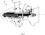
- the system 100 illustratively comprises a plurality of singularities as in 102 provided on an annular member 104 (referred to herein as a propeller beta feedback wheel) carried on the propeller 30.
- a propeller beta feedback wheel carried on the propeller 30.
- the beta feedback wheel 104 is supported for rotation with the propeller 30, which rotates about an axis A.
- the beta feedback wheel 104 is also supported for axial sliding movement along the axis A, e.g. by support members, such as a series of circumferentially spaced beta feedback rods 106 that extend along the axis A.
- a compression spring 108 surrounds an end portion of each rod 106 such that a force exerted by the compression springs 108 (e.g.
- the propeller 30 in response to shifting of the propeller's blades 110 to a reverse pitch position) causes axial movement of the rods 106, and accordingly of the feedback wheel 104, along axis A in the direction of arrow B.
- the propeller 30 comprises a plurality of angularly arranged blades as in 110 each rotatable about the axis A through a plurality of adjustable blade angles, the blade angle being the angle between the chord line (i.e. a line drawn between the leading and trailing edges of the blade) of the propeller blade section and a plane perpendicular to the axis of propeller rotation.
- the propeller 30 may be a reversing propeller 30 having a plurality of modes of operation, such as feather, full reverse, and forward thrust. In some modes of operations, such as feather, the blade angle is positive.
- the propeller 30 may be operated in a reverse mode where the blade angle is negative.
- the feedback wheel 104 is illustratively used to provide blade (or beta) angle position feedback.
- the plurality of singularities as in 102 rotate with the feedback wheel 104 about the axis of rotation A and their passage is detected by at least one sensor 112 provided in a fixed relationship relative to the rotating propeller components.
- the sensor 112 may be any sensor (e.g. a speed transducer) configured to continuously detect passage of the singularities as in 102 during rotation of the propeller 30.
- the sensor 112 is an electrically robust and environmentally sealed non-contact sensor suited for harsh environments and offering superior reliability.
- the sensor 112 may be any suitable inductive sensor having a varying reluctance or a Hall effect.
- the sensor 112 is implemented as a transducer comprising a coil wound around a permanent magnet (not shown).
- the singularities 102 A , 102 B , 102 C may then be made of a magnetically conductive material, e.g. a ferrous metal, to enable the sensor 112 to detect the passage thereof.
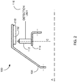
- the sensor 112 is illustratively mounted to a flange 114 of the propeller housing (not shown) so as to be positioned adjacent the plurality of singularities as in 102.
- the sensor 112 is illustratively secured to the propeller 30 so as to extend away from the flange 114 (and towards the singularities 102) along a direction C substantially transverse to the axis of rotation A.
- a single sensor 112 is mounted in close proximity to the beta feedback wheel 104 and the singularities 102.
- two (2) sensors as in 112 may be mounted in a diametrically opposite relationship relative to the singularities 102, which illustratively extend away from the feedback wheel 104 and towards the sensor(s) 112.
- several singularities 102 may be spaced equiangularly about the perimeter of the feedback wheel 104. Other embodiments may apply.
- a detection unit 116 is illustratively electrically connected to the sensor(s) 112 and configured to receive output signal(s) therefrom, the output signal(s) generated upon the sensor(s) 112 detecting the passage of a given singularity as in 102 adjacent thereto, as will be discussed further below.
- the detection unit 116 is illustratively part of the Engine Electronic Control (EEC, not shown) and is configured to provide, on the basis of the signal(s) received from the sensor(s) 112, a blade angle position feedback for the propeller (reference 30 in Fig. 3 ), as will be discussed further below.
- the detection unit 116 may comprise one or more computing devices including, but not limited to, a digital computer, a processor (e.g.
- the detection unit 116 may further determine from the received output signal(s) the rotational speed of the propeller 30 as well as achieve synchrophasing and synchronization. Other applications will be readily understood by a person skilled in the art.
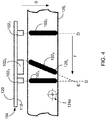
- the singularities 102 comprise a plurality of spaced protrusions or teeth mounted (using any suitable attachment means, such as screws, bolts, and the like) to an inner face 118 of the feedback wheel 104.
- a first set of teeth illustratively at least two first teeth as in 102 A and 102 C , and at least one second tooth, which is referred to herein as a detection tooth 102 B , are provided, with the detection tooth 102 B being positioned between two consecutive ones of the first teeth as in 102 A and 102 C .
- a total of three (3) teeth 102 A , 102 B , 102 C is provided about the perimeter of the feedback wheel 104, as illustrated.
- more than three (3) teeth may be provided.
- more than one detection tooth as in 102 B may be provided for propeller phase detection (e.g. to implement missing tooth detection, as discussed further below) and to maintain operation of the system.
- the number of teeth in turn drives the size of the digital counters provided in the detection unit (as discussed further below).
- Each first tooth as in 102 A or 102 C is illustratively positioned along a direction D, which is substantially parallel to the axis A.
- the detection tooth 102 B is positioned along a direction E angled to the direction D, such that the tooth 102 B is offset relative to the teeth 102 A and 102 C .
- a range of angles may be used to design the detection tooth 102 B .
- the angle between directions E and D may be selected based on optimization of development test data and may include compound angles, e.g. angles comprising a first component providing a radial component and a second component providing a tangential component.
- the angle between directions E and D is between 0.1 and 89.9 degrees.
- the angle is set to 45 degrees so as to maximize the signal change (as detected by the sensor 112 in Fig. 2 ) for a given axial movement of the propeller (reference 30 in Fig. 3 ) resulting from the offset of tooth 102 B relative to teeth 102 A and 102 C .
- Other embodiments may apply.
- each sensor 112 may be mounted to the flange 114 adjacent the inner face 118 of the feedback wheel 104, i.e. inside the feedback wheel 104.
- the teeth 102 A , 102 B , 102 C may be mounted to (e.g. extend away from) an outer face 120 of the beta feedback wheel 104 and each sensor 112 may accordingly be positioned adjacent the outer face 120, about a perimeter of the feedback wheel 104.
- the singularities may comprise slots (not shown) rather than teeth, with the slots being formed or otherwise machined in the feedback wheel 104 and made of a magnetically conductive material, e.g. a ferrous metal.
- the number of singularities as in 102 A , 102 B , 102 C of the beta feedback wheel 104 may be adjusted according to the desired application. For instance, the number of singularities as in 102 A , 102 B , 102 C may be increased to provide low speed detection frequency for the EEC.
- the feedback wheel 104 rotates (e.g. in the direction of arrow F) during rotation of the propeller (reference 30 in Fig. 3 ).
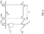
- the sensor 112 detects the passage of each one of the singularities 102 A , 102 B , 102 C and accordingly generates an output voltage signal (also referred to herein as a variable mark/space signal), illustrated by waveform 122 in Fig. 5 .
- an output voltage signal also referred to herein as a variable mark/space signal
- An increase in the sensor's output voltage signal 122 (e.g. a single pulse causing a positive voltage transition) is then produced.
- the given singularity e.g. singularity 102 A
- the pulse shape is inverted and the sensor's output voltage signal 122 is returned to zero.
- the sensor's output voltage signal 122 is received at the detection unit 116, which continuously monitors the signal to detect the positive transition of the voltage waveform. When such a positive transition is detected, the detection unit 116 accordingly determines that the increase in voltage corresponds to detection by the sensor 112 of passage of a singularity (e.g. singularity 102 A ).
- a digital counter (not shown), such as a free-running 20 MHz counter, provided in the detection unit 116 starts counting the number of digital clock cycles until the next singularity (e.g. singularity 102 B ) is detected by the sensor 112, i.e. until the next positive transition in the output voltage 122.
- the counter determines the number of clock cycles between detection of passage of the first teeth 102 A , 102 C and detection of passage of the detection tooth 102 B of the modified beta feedback wheel 104.
- the interval of time between the passage of the first tooth 102 A and the passage of the detection tooth 102 B is indicated as Tm while the interval of time between the passage of the detection tooth 102 B and the passage of the first tooth 102 C is indicated as Ts.
- the detected time intervals Tm and Ts are then stored in the memory for subsequent processing by the detection unit 116.
- the number of teeth as in 102 A , 102 B , 102 C limits the size and/or number of counters within the detection unit 116.
- the size and/or number of the digital counters may be increased to provide low speed detection frequency for the EEC, assuming a fixed digital timebase within the detection unit 116. It should be understood that slowing the fixed digital timebase may also achieve low speed detection frequency but penalizes system accuracy.
- the propeller 30 is a reversing (or reverse-pitch) propeller which may be operated in beta mode for ground reversing or taxis operation.
- the propeller blades (reference 110 in Fig. 3 ) may be moved toward reverse pitch, as discussed above, and a negative blade angle can be allowed to produce a reducing thrust in the aircraft.
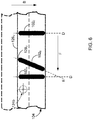
- the feedback wheel 104 begins moving axially forward (in the direction of arrow B in Fig. 3 ) at the low blade angle setting. Forward movement continues until reaching reverse pitch stop. At blade angles higher than the low blade angle setting, the feedback wheel 104 remains stationary.
- the sensor 112 is successively exposed to different sections of the singularities 102, the different sections being taken along the direction E.
- the sensor 112 is indeed in a first position 124a relative to the feedback wheel 104 prior to the propeller entering the reverse mode of operation (e.g. before the feedback wheel 104 begins axial movement).
- the sensor 112 is adjacent a lower edge 126 L of the feedback wheel 104 is exposed to and can accordingly detect the passage of the lower end portion 128 L of the angled tooth 102 B .
- the feedback wheel 104 is gradually displaced along axis A in the direction of arrow B.
- the feedback wheel 104 When the propeller is in the full reverse condition, the feedback wheel 104 has been fully axially displaced and reaches the position illustrated in solid lines in Fig. 6 (with the original position of the feedback wheel 104 being shown in dashed lines). As a result, the sensor 112 is in a second position 124b relative to the displaced feedback wheel 104. In this position 124b, the sensor 112 is adjacent to an upper edge 126 U of the feedback wheel 104 such that the sensor 112 is exposed to and can accordingly detect the passage of the upper end portion 128 U of the angled tooth 102 B .
- the lower end portion 128 L is positioned forward (when taken in the direction of rotation illustrated by arrow F) of the upper end portion 128 U .
- the sensor 112 detects the passing of the tooth 102 B (e.g. the lower end 128 L thereof) earlier (i.e. in less time) than when the feedback wheel 104 is fully displaced with the sensor 112 in position 124b relative to the feedback wheel 104 and the sensor 112 detects the passing of the tooth 102 B (e.g. the upper end 128 U thereof).
- the time taken by the sensor 112 to detect the passing of the tooth 102 B varies as the feedback wheel 104 is displaced axially in the direction of arrow B. Still, since the teeth 102 A , 102 C are not angled but all extend along the direction E, as the feedback wheel 104 moves, the sensor 112 detects passing of each one of the teeth 102 A , 102 C at the same time, regardless of whether the sensor is in position 124a or position 124b.
- the timeframes Tm and Ts are varied as the feedback wheel 104 moves axially along the propeller system and the position of the sensor 112 relative to the feedback wheel 104 varies.
- the section or area of the tooth 102 B observed by the sensor 112 is gradually displaced along the direction E of Fig. 4 and more rearward (relative to direction of arrow F) tooth sections are observed until the most rearward section, e.g. the upper end 128 U , is detected.
- the area of the tooth 102 B observed by the sensor 112 is gradually moved rearward (as illustrated by arrow G), i.e.
- the time interval Tm is increased and the time interval Ts decreased. This in turn alters the spacing relationship between Tm (timeframe between detection by sensor 112 of teeth 102 A and 102 B ) and Ts (timeframe between detection by sensor 112 of teeth 102 B and 102 C ).
- Beta position Ts ⁇ Tm / Ts + Tm
- the detection unit 116 can then apply equation (1) to compute the blade angle position for the propeller (reference 30 in Fig. 3 ) and accordingly the axial position of the propeller system.
- the detection unit 116 can further detect axial movement of the feedback wheel 104 by detecting a change in the spatial relationship between Ts and Tm. This could be done by comparing current values of Ts and Tm to previous values stored in memory and detecting the change in spatial relationship upon detecting a difference in the values.
- the detection unit 116 can electronically decode the sensor's output voltage signal to provide the propeller's rotational speed.
- the rotational speed can be computed on the basis of the sum of the timeframe values (Tm + Ts) and the number of singularities 102 A , 102 B , 102 C , using known computation methods.
- Propeller synchrophasing and synchronization for multi-engine (e.g. twin engine) aircrafts and other applications may further be implemented by removing one or more of the singularities 102 A , 102 B , 102 C from the beta feedback wheel 104 to permit missing tooth pulse detection capability in the engine control electronics. It should be understood that either one of the singularities 102, i.e.
- one of the first teeth as in 102 A , 102 C or one angled teeth as in 102 B may be removed from the feedback wheel 104 to perform missing tooth detection.
- the angled tooth 102 B may be removed such that a gap is created between successive first teeth 102 A .
- Detection of the missing tooth may then provide a special timing position signal.
- the timing position signal can then be used to keep the engines operating at the same revolutions per minute (RPM) and the propeller blades in phase with one another. As a result of such synchrophasing and synchronizing, noise and vibration can be reduced.
- Fig. 7 illustrates a method 200 for electronic beta feedback.
- the method 200 comprises detecting the passage of a first non-offset singularity at step 202.
- the next step 204 is then to count the clock cycles until the passage of an offset singularity is detected.
- the clock cycles until detection of the passage of a second non-offset singularity may then be counted at step 206.
- Detection may be performed using a suitable sensor, such as a sensor as in 112 arranged on a beta feedback wheel as discussed herein above with reference to Fig. 2 , with the non-offset and offset singularities arranged as discussed herein above with reference to Fig. 4 .
- the next step 208 may then be to compute the blade angle position on the basis of the counted clock cycles, e.g.
- the rotation speed of the propeller may also be computed at step 210 using knowledge of the counted clock cycles and the number of singularities and propeller synchrophasing and synchronization may also be performed at step 212 by applying missing tooth detection.
- the annular member may be stationary and the sensor may rotate.
- the sensor and annular member may be operative in connection with another suitable rotating component of the engine indicative of propeller rotation. Relative axial movement between sensor(s) and the annular member may be accomplished in any suitable fashion. Still other modifications which fall within the scope of the present invention will be apparent to those skilled in the art, in light of a review of this disclosure.
Landscapes
- Engineering & Computer Science (AREA)
- Physics & Mathematics (AREA)
- General Physics & Mathematics (AREA)
- Aviation & Aerospace Engineering (AREA)
- Mechanical Engineering (AREA)
- General Engineering & Computer Science (AREA)
- Measurement Of Length, Angles, Or The Like Using Electric Or Magnetic Means (AREA)
- Length Measuring Devices With Unspecified Measuring Means (AREA)
Claims (13)
- Flugzeugpropeller (30), wobei der Propeller (30) um eine Achse (A) drehbar ist, und umfassend eine Vielzahl von Blättern, die jeweils drehbar durch eine Vielzahl von Blattwinkeln sind, und ein Blattwinkelpositions-Rückkopplungssystem (100), wobei das Blattwinkelpositions-Rückkopplungssystem Folgendes umfasst:ein ringförmige Element (104), das operativ verbunden ist, um mit dem Propeller (30) zu drehen, das ringförmige Element (104) umfassend mindestens zwei in Umfangsrichtung beabstandete erste Singularitäten (102A, 102C), die sich im Wesentlichen parallel zu der Achse (A) erstrecken, und mindestens eine zweite Singularität (102B), die sich nicht parallel zu den ersten Singularitäten (102A, 102C) erstreckt;mindestens einen Sensor (112), der fest anliegend an dem ringförmigen Element (104) montiert ist, wobei der mindestens eine Sensor (112) konfiguriert ist, um nacheinander einen Vorbeilauf von jedem der mindestens zwei ersten Singularitäten (102A, 102C) und der mindestens einen zweite Singularität (102B) zu erfassen, während das ringförmige Element (104) gedreht und axial verschoben wird und um entsprechend ein Sensorsignal zu erzeugen, wobei das ringförmige Element (104) und der mindestens eine Sensor (112) für eine relative axiale Verschiebung zwischen einer ersten relativen axialen Position und einer zweiten relativen axialen Position konfiguriert sind; undeine Erfassungseinheit (116), die mit dem mindestens einen Sensor (112) verbunden ist, um das Sensorsignal davon zu empfangen, Bestimmen eines verstrichenen Zeitintervalls zwischen dem Vorbeilauf von aufeinanderfolgenden der mindestens zwei ersten Singularitäten (102A, 102C) und der mindestens einen zweiten Singularität (102B) auf der Basis des Sensorsignals, und Berechnen aus dem Zeitintervall einer Blattwinkelposition für die Vielzahl von Blättern, wobei die Erfassungseinheit (116) konfiguriert ist, um den Propeller (30) eines ersten Motors mit dem Propeller (30) von mindestens einem zweiten Motor auf der Basis des Sensorsignals zu synchronisieren, dadurch gekennzeichnet, dass nach Entfernen von dem ringförmigen Element (104) einer gegebenen einen der Singularitäten (102A, 102B, 102C) die Erfassungseinheit (116) konfiguriert ist, um auf der Basis des Sensorsignals ein Entfernen der gegebenen einen der Singularitäten (102A, 102B, 102C) zu erfassen; und dadurch, dass der Propeller (30) mindestens eine erste Betriebsart hat, wo die Vielzahl von Blättern mit einem positiven Blattwinkel betrieben wird, und eine zweite Betriebsart, wo die Vielzahl von Blättern mit einem negativen Blattwinkel betrieben wird, wobei die erste relative axiale Position der ersten Betriebsart entspricht, und die zweite relative axiale Position der zweiten Betriebsart entspricht.
- Flugzeugpropeller (30) nach Anspruch 1, wobei das ringförmige Element (104) für eine axiale Verschiebung relativ zu einem fest montierten mindestens einen Sensor (112) montiert ist.
- Flugzeugpropeller (30) nach Anspruch 1 oder 2, wobei jede der mindestens einen zweiten Singularität (102B) zwischen zwei aufeinanderfolgenden der mindestens zwei ersten Singularitäten (102A, 102C) positioniert ist.
- Flugzeugpropeller (30) nach einem der Ansprüche 1 bis 3, wobei die Erfassungseinheit (116) für ein Berechnen eines ersten Zeitintervalls Tm zwischen dem Vorbeilauf einer ersten der mindestens zwei ersten Singularitäten (102A, 102C) und dem Vorbeilauf einer ersten der mindestens einen zweiten Singularität (102B) ist, Berechnen eines zweiten Zeitintervalls Ts zwischen dem Vorbeilauf der ersten der mindestens einen zweiten Singularität (102B) und dem Vorbeilauf einer zweiten der mindestens zwei ersten Singularitäten (102A, 102C), wobei die erste der mindestens einen zweiten Singularität (102B) zwischen der ersten und der zweiten der mindestens zwei ersten Singularitäten (102A, 102C) positioniert ist, und Berechnen der Blattwinkelposition wie folgt: Blattwinkelposition = (Ts-Tm)/(Ts+Tm).
- Flugzeugpropeller (30) nach Anspruch 4, wobei das ringförmige Element (104) um die Achse (A) drehbar und axial ihrer entlang verschiebbar ist, um verschiedene Abschnitte der mindestens einen zweiten Singularität (102B) an den mindestens einen Sensor (112) auszusetzen, wobei das ringförmige Element (104), wenn es in der ersten Position ist, einen vorderen Abschnitt der mindestens einen zweiten Singularität (102B) an den mindestens einen Sensor (112) aussetzt, wenn es in der zweiten Position ist, einen hinteren Abschnitt der mindestens einen zweiten Singularität (102B) an den mindestens einen Sensor (112) aussetzt, und im Übergang zwischen der ersten und der zweiten Position aufeinanderfolgende Abschnitte der mindestens einen zweiten Singularität (102B) aussetzt, die zwischen dem vorderen und dem hinteren Abschnitt bereitgestellt sind.
- Flugzeugpropeller (30) nach Anspruch 5, wobei, während das ringförmige Element (104) zwischen der ersten und der zweiten Position gedreht und axial verschoben wird, eine Zeit, an der der mindestens eine Sensor (112) einen gegebenen der Abschnitte der mindestens einen zweiten Singularität (102B) erfasst, sich von einer Zeit unterscheidet, an der der mindestens eine Sensor (112) einen nachfolgenden der Abschnitte der mindestens einen zweiten Singularität (102B) erfasst, sodass das erste und das zweite Zeitintervall, die von der Erfassungseinheit (116) zusätzlich zur Erfassung eines ersten Vorbeilaufs der mindestens zwei ersten Singularitäten (102A, 102C) und der mindestens einen zweiten Singularität (102B) berechnet werden, sich von dem ersten und dem zweiten Zeitintervall unterscheidet, die von der Erfassungseinheit (116) zusätzlich zur Erkennung eines nachfolgenden Vorbeilaufs der mindestens zwei ersten Singularitäten (102A, 102C) und der mindestens einen zweiten Singularität (102B) berechnet werden.
- Flugzeugpropeller (30) nach einem der Ansprüche 4 bis 6, ferner umfassend einen Speicher mit darin gespeicherten daten, die eine Anzahl der mindestens zwei ersten Singularitäten (102A, 102C) und der mindestens einen zweiten Singularität (102B) angeben, die an dem ringförmigen Element (114) bereitgestellt sind, wobei die Erfassungseinheit (116) konfiguriert ist, um die Daten aus dem Speicher abzurufen, um eine Summe des ersten Zeitintervalls und des zweiten Zeitintervalls zu berechnen, und um eine Drehgeschwindigkeit des Propellers (30) auf der Basis der Anzahl von Singularitäten und der Summe zu bestimmen.
- Flugzeugpropeller (30) nach einem der Ansprüche 1 bis 7, wobei die Singularitäten (102A, 102B, 102C) eines der folgenden sind:an einer Innenseite des ringförmigen Elements (104), und wobei der mindestens eine Sensor (112) anliegend an der Innenseite montiert ist; undan einer Außenseite des ringförmigen Elements (104), und wobei der mindestens eine Sensor (112) anliegend an der Außenseite montiert ist.
- Flugzeugpropeller (30) nach einem der Ansprüche 1 bis 8, wobei die mindestens zwei ersten Singularitäten (102A, 102C) und die mindestens eine zweite Singularität (102B) ausgewählt sind aus einer Gruppe bestehend aus einem hervorstehenden Zahn, der sich weg von dem ringförmigen Element (104) und einem in dem ringförmigen Element (104) gebildeten Schlitz erstreckt.
- Flugzeugpropeller (30) nach einem der Ansprüche 1 bis 9, wobei der mindestens eine Sensor (112) einen ersten Sensor diametral gegenüber einem zweiten Sensor umfasst.
- Verfahren für Blattwinkelpositions-Rückkopplung für einen Flugzeugpropeller (30), wobei der Propeller (30) um eine Achse (A) drehbar ist und eine Vielzahl von Blättern umfasst, die jeweils drehbar durch eine Vielzahl von Blattwinkeln sind, der Propeller (30) mindestens eine erste Betriebsart hat, bei der die Vielzahl von Blättern mit einem positiven Blattwinkel betrieben werden, und eine zweite Betriebsart, bei der die Vielzahl von Blättern mit einem negativen Blattwinkel betrieben werden, wobei das Verfahren Folgendes umfasst:Empfangen eines Sensorsignals von mindestens einem Sensor (112), der fest anliegend an ein ringförmiges Element (104) befestigt ist und operativ verbunden ist, um mit dem Propeller (30) zu drehen, das ringförmige Element (104) umfassend mindestens zwei in Umfangsrichtung beabstandete erste Singularitäten (102A, 102CC), die sich im Wesentlichen parallel zu der Achse (A) erstrecken, und mindestens eine zweite Singularität (102B), die sich nicht parallel zu den ersten Singularitäten (102A, 102C) erstreckt, wobei der mindestens eine Sensor (112) konfiguriert ist, um nacheinander einen Vorbeilauf von jedem der mindestens zwei ersten Singularitäten (102A, 102C) und der mindestens einen zweite Singularität (102B) zu erfassen, während das ringförmige Element (104) gedreht und axial verschoben wird und um entsprechend ein Sensorsignal zu erzeugen, wobei das ringförmige Element (104) und der mindestens eine Sensor (112) für eine relative axiale Verschiebung zwischen einer ersten relativen axialen Position und einer zweiten relativen axialen Position konfiguriert sind, wobei die erste Position der ersten Betriebsart und die zweite Position der zweiten Betriebsart entspricht;Bestimmen eines verstrichenen Zeitintervalls zwischen dem Vorbeilauf von aufeinanderfolgenden der mindestens zwei ersten Singularitäten (102A, 102C) und der mindestens einen zweiten Singularität (102B) auf der Basis des Sensorsignals; undBerechnen aus dem Zeitintervall einer Blattwinkelposition für die Vielzahl von Blättern, ferner umfassend nach einem Entfernen von dem ringförmigen Element (104) einer gegebenen der Singularitäten (102A, 102B, 102C) ein Erfassen auf der Basis des Sensorsignals eines Entfernens der gegebenen der Singularitäten (102A, 102B, 102C) und Synchronisieren des Propellers (30) eines ersten Motors mit dem Propeller (30) von mindestens einem zweiten Motor auf der Basis des Sensorsignals.
- Verfahren nach Anspruch 11, wobei ein Bestimmen des Zeitintervalls ein Berechnen eines ersten Zeitintervalls Tm zwischen dem Vorbeilauf einer ersten der mindestens zwei ersten Singularitäten (102A, 102C) und dem Vorbeilauf einer ersten der mindestens einen zweiten Singularität (102B), und Berechnen eines zweiten Zeitintervalls Ts zwischen dem Vorbeilauf der ersten der mindestens einen zweiten Singularität (102B) und dem Vorbeilauf einer zweiten der mindestens zwei ersten Singularitäten (102A, 102C) umfasst, wobei die erste der mindestens einen zweiten Singularität (102B) zwischen der ersten und der zweiten der mindestens zwei ersten Singularitäten (102A, 102C) positioniert ist, und ferner wobei die Blattwinkelposition wie folgt berechnet wird: Blattwinkelposition = (Ts-Tm)/(Ts+Tm).
- Verfahren nach Anspruch 11 oder 12, ferner umfassend ein Abrufen von Daten aus einem Speicher, die eine Anzahl von Singularitäten (102A, 102B, 102C) angeben, Berechnen einer Summe des ersten Zeitintervalls und des zweiten Zeitintervalls, und Bestimmen einer Drehgeschwindigkeit des Propellers (30) auf der Basis der Anzahl von Singularitäten (102A, 102B, 102C) und der Summe.
Applications Claiming Priority (2)
| Application Number | Priority Date | Filing Date | Title |
|---|---|---|---|
| US201361907246P | 2013-11-21 | 2013-11-21 | |
| EP14194263.1A EP2876046B1 (de) | 2013-11-21 | 2014-11-21 | System und Verfahren zur elektronischen Propellerblattwinkelpositionsrückkopplung |
Related Parent Applications (1)
| Application Number | Title | Priority Date | Filing Date |
|---|---|---|---|
| EP14194263.1A Division EP2876046B1 (de) | 2013-11-21 | 2014-11-21 | System und Verfahren zur elektronischen Propellerblattwinkelpositionsrückkopplung |
Publications (2)
| Publication Number | Publication Date |
|---|---|
| EP3124377A1 EP3124377A1 (de) | 2017-02-01 |
| EP3124377B1 true EP3124377B1 (de) | 2018-06-13 |
Family
ID=52020949
Family Applications (2)
| Application Number | Title | Priority Date | Filing Date |
|---|---|---|---|
| EP16189338.3A Active EP3124377B1 (de) | 2013-11-21 | 2014-11-21 | System und verfahren zur elektronischen propellerblattwinkelpositionsrückkopplung |
| EP14194263.1A Active EP2876046B1 (de) | 2013-11-21 | 2014-11-21 | System und Verfahren zur elektronischen Propellerblattwinkelpositionsrückkopplung |
Family Applications After (1)
| Application Number | Title | Priority Date | Filing Date |
|---|---|---|---|
| EP14194263.1A Active EP2876046B1 (de) | 2013-11-21 | 2014-11-21 | System und Verfahren zur elektronischen Propellerblattwinkelpositionsrückkopplung |
Country Status (3)
| Country | Link |
|---|---|
| US (1) | US9821901B2 (de) |
| EP (2) | EP3124377B1 (de) |
| CA (1) | CA2871835C (de) |
Families Citing this family (43)
| Publication number | Priority date | Publication date | Assignee | Title |
|---|---|---|---|---|
| US10487682B2 (en) * | 2015-05-15 | 2019-11-26 | Pratt & Whitney Canada Corp. | Automated propeller feather testing |
| US10823061B2 (en) * | 2016-07-15 | 2020-11-03 | General Electric Company | Engine air inlet having a double-panel heated wall |
| US10486827B2 (en) * | 2016-08-17 | 2019-11-26 | Pratt & Whitney Canada Corp. | Apparatus and methods for aircraft propeller control |
| US10435140B2 (en) * | 2016-08-17 | 2019-10-08 | Pratt & Whitney Canada Corp. | System and method for electronic propeller blade angle position feedback with angled pairs of teeth |
| CN106741859A (zh) * | 2016-12-12 | 2017-05-31 | 惠阳航空螺旋桨有限责任公司 | 螺旋桨桨叶角度的时时监测装置 |
| EP3354561A1 (de) | 2017-01-30 | 2018-08-01 | Ge Avio S.r.l. | System und verfahren zur lokalisierung der segelwinkelstellung von propellerblättern |
| US10577078B2 (en) | 2017-04-24 | 2020-03-03 | General Electric Company | Systems and methods for electronic measurement of propeller blade angle |
| US10889367B2 (en) | 2017-04-24 | 2021-01-12 | Pratt & Whitney Canada Corp. | Feedback system for pitch-adjustable blades of aircraft bladed rotor |
| FR3075353B1 (fr) * | 2017-12-14 | 2020-05-29 | Safran Aircraft Engines | Mesure non intrusive du calage d'une pale |
| US20190234766A1 (en) * | 2018-01-26 | 2019-08-01 | Pratt & Whitney Canada Corp. | Magnetic sensor with bifilar windings |
| US10864979B2 (en) * | 2018-06-27 | 2020-12-15 | Pratt & Whitney Canada Corp. | System and method for propeller feedback ring position detection |
| US10745110B2 (en) | 2018-06-29 | 2020-08-18 | Pratt & Whitney Canada Corp. | Propeller blade synchrophasing using phonic wheel |
| US10801360B2 (en) * | 2018-06-29 | 2020-10-13 | Pratt & Whitney Canada Corp. | Phonic wheel with output voltage tuning |
| US10822105B2 (en) | 2018-07-04 | 2020-11-03 | Pratt & Whitney Canada Corp. | Method and system for controlling a crossing threshold used in determining rotational speed of a propeller |
| US11046422B2 (en) * | 2018-07-16 | 2021-06-29 | Pratt & Whitney Canada Corp. | Propeller blade angle feedback arrangement and method |
| US11279465B2 (en) * | 2018-07-16 | 2022-03-22 | Pratt & Whitney Canada Corp. | Propeller blade angle feedback arrangement and method |
| CN109443283B (zh) * | 2018-09-30 | 2020-09-04 | 长安大学 | 一种飞行器便携式自由间隙检测装置 |
| US11691748B2 (en) | 2018-10-15 | 2023-07-04 | Pratt & Whitney Canada Corp. | Reverse thrust in multi-engine propeller aircraft |
| US10850831B2 (en) * | 2018-12-21 | 2020-12-01 | Honeywell International Inc. | Propeller pitch control system for aircraft turboprop engines |
| US10829201B2 (en) * | 2019-03-20 | 2020-11-10 | Pratt & Whitney Canada Corp. | Blade angle position feedback system with extended markers |
| US11414175B2 (en) | 2019-04-01 | 2022-08-16 | Pratt & Whitney Canada Corp. | Method and system for operating an aircraft powerplant |
| US11643187B2 (en) | 2019-04-09 | 2023-05-09 | Pratt & Whitney Canada Corp. | Blade angle position feedback system with profiled marker terminations |
| US11554850B2 (en) | 2019-04-25 | 2023-01-17 | Pratt & Whitney Canada Corp. | Blade angle position feedback system with offset sensors |
| US11371825B2 (en) | 2019-05-31 | 2022-06-28 | Pratt & Whitney Canada Corp. | Feedback device with differing magnetic permeability zones |
| US11333020B2 (en) * | 2019-05-31 | 2022-05-17 | Pratt & Whitney Canada Corp. | Feedback device with non-axially aligned position markers |
| US11046423B2 (en) | 2019-07-18 | 2021-06-29 | Pratt & Whitney Canada Corp. | Blade angle position feedback system with magnetic shield |
| US11286038B2 (en) | 2019-09-03 | 2022-03-29 | Pratt & Whitney Canada Corp. | Pitch control assembly for an aircraft-bladed rotor |
| US11597502B2 (en) | 2019-09-05 | 2023-03-07 | Pratt & Whitney Canada Corp. | Signal amplification in blade angle position feedback system |
| US11365691B2 (en) | 2019-09-05 | 2022-06-21 | Pratt & Whitney Canada Corp. | Blade angle position feedback system with embedded markers |
| US11505307B2 (en) | 2019-10-21 | 2022-11-22 | Pratt & Whitney Canada Corp. | Phonic wheel and related system and method |
| US11428116B2 (en) | 2019-11-29 | 2022-08-30 | Pratt & Whitney Canada Corp. | System and method for measuring an axial position of a rotating component of an engine |
| CN111268159B (zh) * | 2019-12-08 | 2023-05-23 | 惠阳航空螺旋桨有限责任公司 | 一种螺旋桨变距限动结构 |
| US11420772B2 (en) | 2019-12-17 | 2022-08-23 | Pratt & Whitney Canada Corp. | System and method for determining an axial position of a feedback device |
| US11255264B2 (en) | 2020-02-25 | 2022-02-22 | General Electric Company | Frame for a heat engine |
| US11326519B2 (en) | 2020-02-25 | 2022-05-10 | General Electric Company | Frame for a heat engine |
| US11560843B2 (en) | 2020-02-25 | 2023-01-24 | General Electric Company | Frame for a heat engine |
| CN111272132B (zh) * | 2020-03-31 | 2021-06-29 | 中国航发动力股份有限公司 | 一种可调整流叶片旋转角度检测装置及检测方法 |
| US20220185451A1 (en) * | 2020-12-11 | 2022-06-16 | Pratt & Whitney Canada Corp. | Test rig and method for blade pitch measurement system |
| US11767769B2 (en) | 2020-12-11 | 2023-09-26 | Pratt & Whitney Canada Corp. | Method and system for testing a sensor of a propeller blade angle position feedback system |
| US20220363404A1 (en) * | 2021-05-14 | 2022-11-17 | Beta Air, Llc | Systems and methods for monitoring health of an electric vertical take-off and landing vehicle |
| FR3137756B1 (fr) * | 2022-07-05 | 2025-01-03 | Safran Aircraft Engines | Dispositif de mesure d’angle de calage et procédé de mesure d’angle de calage associé |
| US12473843B2 (en) * | 2023-02-13 | 2025-11-18 | Pratt & Whitney Canada Corp. | Hybrid electric propulsion system with pitch change mechanism operation |
| US12391362B2 (en) | 2023-04-18 | 2025-08-19 | Pratt & Whitney Canada Corp. | System and method for measuring an axial position of a rotating component |
Family Cites Families (26)
| Publication number | Priority date | Publication date | Assignee | Title |
|---|---|---|---|---|
| US4934825A (en) | 1987-12-22 | 1990-06-19 | United Technologies Corporation | Propeller phase control apparatus |
| GB2221306A (en) | 1988-07-29 | 1990-01-31 | Dowty Rotol Ltd | Assembly for determining the longitudinal displacement of a rotating shaft |
| US4948337A (en) | 1989-05-01 | 1990-08-14 | United Technologies Corporation | Aircraft engine propulsor blade pitch sensing |
| EP0436231B1 (de) * | 1989-12-30 | 1996-03-06 | Toyota Jidosha Kabushiki Kaisha | Blattverstellsteuerung für Propeller mit veränderbarer Steigung |
| JPH0524585A (ja) * | 1991-07-25 | 1993-02-02 | Toyota Motor Corp | 可変ピツチプロペラのピツチ制御装置 |
| US5284418A (en) * | 1991-07-29 | 1994-02-08 | Toyota Jidosha Kabushiki Kaisha | Electric pitch control apparatus for variable pitch propeller capable of controlling the pitch angle based instantaneous operational conditions of the propeller |
| US5174718A (en) | 1991-08-12 | 1992-12-29 | United Technologies Corporation | Blade pitch change control system |
| US5715162A (en) | 1992-10-13 | 1998-02-03 | United Technologies Corporation | Correlative filter for a synchrophaser |
| FR2754310B1 (fr) * | 1996-10-04 | 1998-11-13 | Renault Sport | Groupe motopropulseur pour avion et son procede de commande |
| US5997250A (en) * | 1997-01-09 | 1999-12-07 | Catercopters, Llc | Method and apparatus for controlling pitch of an aircraft propeller |
| US5865599A (en) | 1997-03-11 | 1999-02-02 | United Technologies Corporation | System and process for direct blade angle measurement in propulsion systems |
| JPH11255199A (ja) * | 1998-03-10 | 1999-09-21 | Toyota Motor Corp | 航空機の推力制御装置 |
| US6213713B1 (en) | 1998-12-31 | 2001-04-10 | United Technologies Corporation | Apparatus for indicating pitch angle of a propeller blade |
| US20040018914A1 (en) | 2002-07-29 | 2004-01-29 | Stolfus Joel D. | Linear position sensing employing two geartooth sensors, a helical gear and a spur gear |
| US8651811B2 (en) | 2005-11-16 | 2014-02-18 | Hamilton Sundstrand | Control logic for a propeller system |
| DE102006029057A1 (de) | 2006-06-24 | 2008-01-03 | Airbus Deutschland Gmbh | Verstellpropeller |
| US7281482B1 (en) * | 2006-09-25 | 2007-10-16 | The United States Of America Represented By The Secretary Of The Navy | Side thruster performance improvement with power optimization controller |
| US20100108806A1 (en) * | 2008-10-08 | 2010-05-06 | Searete Llc, A Limited Liability Corporation Of The State Of Delaware | Hybrid propulsive engine including at least one independently rotatable propeller/fan |
| US8465257B1 (en) * | 2008-10-31 | 2013-06-18 | Brp Us Inc. | Variable pitch propeller |
| GB2465575A (en) | 2008-11-21 | 2010-05-26 | Rolls Royce Plc | Displacement measurement / rotor blade pitch measurement arrangement |
| FR2943620B1 (fr) * | 2009-03-27 | 2012-08-17 | Eurocopter France | Procede et dispositif pour optimiser le point de fonctionnement d'helices propulsives disposees de part et d'autre du fuselage d'un giravion |
| US9272778B2 (en) * | 2009-06-04 | 2016-03-01 | Airbus Helicopters | Device for assisting in piloting hybrid helicopter, hybrid helicopter provided with such device, and method implemented by such device |
| FR2946322B1 (fr) * | 2009-06-04 | 2011-06-17 | Eurocopter France | Dispositif d'aide au pilotage d'un helicoptere hybride, helicoptere hybride muni d'un tel dispositif et procede mis en oeuvre par ledit dispositif |
| US8689538B2 (en) * | 2009-09-09 | 2014-04-08 | The Boeing Company | Ultra-efficient propulsor with an augmentor fan circumscribing a turbofan |
| US8464511B1 (en) | 2012-01-06 | 2013-06-18 | Hamilton Sundstrand Corporation | Magnetically coupled contra-rotating propulsion stages |
| US9512736B2 (en) | 2012-05-14 | 2016-12-06 | United Technologies Corporation | Monitoring one or more turbine engine rotor blades by correlating measurement data and reference data as a function of time |
-
2014
- 2014-11-18 US US14/546,252 patent/US9821901B2/en active Active
- 2014-11-19 CA CA2871835A patent/CA2871835C/en active Active
- 2014-11-21 EP EP16189338.3A patent/EP3124377B1/de active Active
- 2014-11-21 EP EP14194263.1A patent/EP2876046B1/de active Active
Non-Patent Citations (1)
| Title |
|---|
| None * |
Also Published As
| Publication number | Publication date |
|---|---|
| CA2871835C (en) | 2023-03-28 |
| EP2876046A1 (de) | 2015-05-27 |
| EP3124377A1 (de) | 2017-02-01 |
| CA2871835A1 (en) | 2015-05-21 |
| US20150139798A1 (en) | 2015-05-21 |
| EP2876046B1 (de) | 2016-10-05 |
| US9821901B2 (en) | 2017-11-21 |
Similar Documents
| Publication | Publication Date | Title |
|---|---|---|
| EP3124377B1 (de) | System und verfahren zur elektronischen propellerblattwinkelpositionsrückkopplung | |
| US12365443B2 (en) | Apparatus and methods for aircraft propeller control | |
| EP3284665B1 (de) | System und verfahren für elektronische propellerblattwinkelpositionsrückmeldung mit abgewinkelten paaren von zähnen | |
| EP3591409B1 (de) | Verfahren und system zum steuern einer überschreitungsschwelle zum bestimmen der drehzahl eines propellers | |
| EP3396304B1 (de) | Rückkopplungssystem für neigungsverstellbare blätter eines luftfahrzeugblattrotors | |
| CN110657030B (zh) | 用于对多发动机飞机进行同步定相的系统和方法 | |
| EP4276012A2 (de) | Blattwinkelpositionsrückkopplungssystem mit versatzsensoren | |
| EP4324750A2 (de) | Anordnung und verfahren zur propellerblattwinkelrückmeldung | |
| EP3838745A1 (de) | System und verfahren zur bestimmung einer axialen position einer rückkopplungsvorrichtung | |
| EP3712057B1 (de) | Schaufelwinkelpositionsrückmeldungssystem mit erweiterten markern | |
| EP4343284A2 (de) | Blattwinkelverstellsteuerungsanordnung für einen flugzeugrotor | |
| EP3766776B1 (de) | Blattwinkelpositionsrückkopplungssystem mit magnetischer abschirmung | |
| EP3722204A1 (de) | Blattwinkelpositionrückmeldesystem mit profilierten markierungsenden |
Legal Events
| Date | Code | Title | Description |
|---|---|---|---|
| PUAI | Public reference made under article 153(3) epc to a published international application that has entered the european phase |
Free format text: ORIGINAL CODE: 0009012 |
|
| STAA | Information on the status of an ep patent application or granted ep patent |
Free format text: STATUS: THE APPLICATION HAS BEEN PUBLISHED |
|
| AC | Divisional application: reference to earlier application |
Ref document number: 2876046 Country of ref document: EP Kind code of ref document: P |
|
| AK | Designated contracting states |
Kind code of ref document: A1 Designated state(s): AL AT BE BG CH CY CZ DE DK EE ES FI FR GB GR HR HU IE IS IT LI LT LU LV MC MK MT NL NO PL PT RO RS SE SI SK SM TR |
|
| STAA | Information on the status of an ep patent application or granted ep patent |
Free format text: STATUS: REQUEST FOR EXAMINATION WAS MADE |
|
| 17P | Request for examination filed |
Effective date: 20170731 |
|
| RBV | Designated contracting states (corrected) |
Designated state(s): AL AT BE BG CH CY CZ DE DK EE ES FI FR GB GR HR HU IE IS IT LI LT LU LV MC MK MT NL NO PL PT RO RS SE SI SK SM TR |
|
| GRAP | Despatch of communication of intention to grant a patent |
Free format text: ORIGINAL CODE: EPIDOSNIGR1 |
|
| STAA | Information on the status of an ep patent application or granted ep patent |
Free format text: STATUS: GRANT OF PATENT IS INTENDED |
|
| RIC1 | Information provided on ipc code assigned before grant |
Ipc: G01D 5/14 20060101ALN20171206BHEP Ipc: G01D 5/245 20060101ALN20171206BHEP Ipc: B64C 11/30 20060101AFI20171206BHEP Ipc: B64C 11/06 20060101ALN20171206BHEP Ipc: G01P 3/488 20060101ALI20171206BHEP Ipc: G01P 3/487 20060101ALI20171206BHEP |
|
| INTG | Intention to grant announced |
Effective date: 20171222 |
|
| GRAS | Grant fee paid |
Free format text: ORIGINAL CODE: EPIDOSNIGR3 |
|
| GRAA | (expected) grant |
Free format text: ORIGINAL CODE: 0009210 |
|
| STAA | Information on the status of an ep patent application or granted ep patent |
Free format text: STATUS: THE PATENT HAS BEEN GRANTED |
|
| AC | Divisional application: reference to earlier application |
Ref document number: 2876046 Country of ref document: EP Kind code of ref document: P |
|
| AK | Designated contracting states |
Kind code of ref document: B1 Designated state(s): AL AT BE BG CH CY CZ DE DK EE ES FI FR GB GR HR HU IE IS IT LI LT LU LV MC MK MT NL NO PL PT RO RS SE SI SK SM TR |
|
| REG | Reference to a national code |
Ref country code: GB Ref legal event code: FG4D |
|
| REG | Reference to a national code |
Ref country code: CH Ref legal event code: EP Ref country code: AT Ref legal event code: REF Ref document number: 1008224 Country of ref document: AT Kind code of ref document: T Effective date: 20180615 |
|
| REG | Reference to a national code |
Ref country code: IE Ref legal event code: FG4D |
|
| REG | Reference to a national code |
Ref country code: DE Ref legal event code: R096 Ref document number: 602014027195 Country of ref document: DE |
|
| REG | Reference to a national code |
Ref country code: NL Ref legal event code: MP Effective date: 20180613 |
|
| REG | Reference to a national code |
Ref country code: FR Ref legal event code: PLFP Year of fee payment: 5 |
|
| REG | Reference to a national code |
Ref country code: LT Ref legal event code: MG4D |
|
| PG25 | Lapsed in a contracting state [announced via postgrant information from national office to epo] |
Ref country code: SE Free format text: LAPSE BECAUSE OF FAILURE TO SUBMIT A TRANSLATION OF THE DESCRIPTION OR TO PAY THE FEE WITHIN THE PRESCRIBED TIME-LIMIT Effective date: 20180613 Ref country code: BG Free format text: LAPSE BECAUSE OF FAILURE TO SUBMIT A TRANSLATION OF THE DESCRIPTION OR TO PAY THE FEE WITHIN THE PRESCRIBED TIME-LIMIT Effective date: 20180913 Ref country code: FI Free format text: LAPSE BECAUSE OF FAILURE TO SUBMIT A TRANSLATION OF THE DESCRIPTION OR TO PAY THE FEE WITHIN THE PRESCRIBED TIME-LIMIT Effective date: 20180613 Ref country code: CY Free format text: LAPSE BECAUSE OF FAILURE TO SUBMIT A TRANSLATION OF THE DESCRIPTION OR TO PAY THE FEE WITHIN THE PRESCRIBED TIME-LIMIT Effective date: 20180613 Ref country code: NO Free format text: LAPSE BECAUSE OF FAILURE TO SUBMIT A TRANSLATION OF THE DESCRIPTION OR TO PAY THE FEE WITHIN THE PRESCRIBED TIME-LIMIT Effective date: 20180913 Ref country code: LT Free format text: LAPSE BECAUSE OF FAILURE TO SUBMIT A TRANSLATION OF THE DESCRIPTION OR TO PAY THE FEE WITHIN THE PRESCRIBED TIME-LIMIT Effective date: 20180613 Ref country code: ES Free format text: LAPSE BECAUSE OF FAILURE TO SUBMIT A TRANSLATION OF THE DESCRIPTION OR TO PAY THE FEE WITHIN THE PRESCRIBED TIME-LIMIT Effective date: 20180613 |
|
| PG25 | Lapsed in a contracting state [announced via postgrant information from national office to epo] |
Ref country code: GR Free format text: LAPSE BECAUSE OF FAILURE TO SUBMIT A TRANSLATION OF THE DESCRIPTION OR TO PAY THE FEE WITHIN THE PRESCRIBED TIME-LIMIT Effective date: 20180914 Ref country code: HR Free format text: LAPSE BECAUSE OF FAILURE TO SUBMIT A TRANSLATION OF THE DESCRIPTION OR TO PAY THE FEE WITHIN THE PRESCRIBED TIME-LIMIT Effective date: 20180613 Ref country code: LV Free format text: LAPSE BECAUSE OF FAILURE TO SUBMIT A TRANSLATION OF THE DESCRIPTION OR TO PAY THE FEE WITHIN THE PRESCRIBED TIME-LIMIT Effective date: 20180613 Ref country code: RS Free format text: LAPSE BECAUSE OF FAILURE TO SUBMIT A TRANSLATION OF THE DESCRIPTION OR TO PAY THE FEE WITHIN THE PRESCRIBED TIME-LIMIT Effective date: 20180613 |
|
| REG | Reference to a national code |
Ref country code: AT Ref legal event code: MK05 Ref document number: 1008224 Country of ref document: AT Kind code of ref document: T Effective date: 20180613 |
|
| PG25 | Lapsed in a contracting state [announced via postgrant information from national office to epo] |
Ref country code: NL Free format text: LAPSE BECAUSE OF FAILURE TO SUBMIT A TRANSLATION OF THE DESCRIPTION OR TO PAY THE FEE WITHIN THE PRESCRIBED TIME-LIMIT Effective date: 20180613 |
|
| PG25 | Lapsed in a contracting state [announced via postgrant information from national office to epo] |
Ref country code: RO Free format text: LAPSE BECAUSE OF FAILURE TO SUBMIT A TRANSLATION OF THE DESCRIPTION OR TO PAY THE FEE WITHIN THE PRESCRIBED TIME-LIMIT Effective date: 20180613 Ref country code: AT Free format text: LAPSE BECAUSE OF FAILURE TO SUBMIT A TRANSLATION OF THE DESCRIPTION OR TO PAY THE FEE WITHIN THE PRESCRIBED TIME-LIMIT Effective date: 20180613 Ref country code: EE Free format text: LAPSE BECAUSE OF FAILURE TO SUBMIT A TRANSLATION OF THE DESCRIPTION OR TO PAY THE FEE WITHIN THE PRESCRIBED TIME-LIMIT Effective date: 20180613 Ref country code: PL Free format text: LAPSE BECAUSE OF FAILURE TO SUBMIT A TRANSLATION OF THE DESCRIPTION OR TO PAY THE FEE WITHIN THE PRESCRIBED TIME-LIMIT Effective date: 20180613 Ref country code: IS Free format text: LAPSE BECAUSE OF FAILURE TO SUBMIT A TRANSLATION OF THE DESCRIPTION OR TO PAY THE FEE WITHIN THE PRESCRIBED TIME-LIMIT Effective date: 20181013 Ref country code: SK Free format text: LAPSE BECAUSE OF FAILURE TO SUBMIT A TRANSLATION OF THE DESCRIPTION OR TO PAY THE FEE WITHIN THE PRESCRIBED TIME-LIMIT Effective date: 20180613 |
|
| PG25 | Lapsed in a contracting state [announced via postgrant information from national office to epo] |
Ref country code: IT Free format text: LAPSE BECAUSE OF FAILURE TO SUBMIT A TRANSLATION OF THE DESCRIPTION OR TO PAY THE FEE WITHIN THE PRESCRIBED TIME-LIMIT Effective date: 20180613 Ref country code: SM Free format text: LAPSE BECAUSE OF FAILURE TO SUBMIT A TRANSLATION OF THE DESCRIPTION OR TO PAY THE FEE WITHIN THE PRESCRIBED TIME-LIMIT Effective date: 20180613 |
|
| REG | Reference to a national code |
Ref country code: DE Ref legal event code: R097 Ref document number: 602014027195 Country of ref document: DE |
|
| PLBE | No opposition filed within time limit |
Free format text: ORIGINAL CODE: 0009261 |
|
| STAA | Information on the status of an ep patent application or granted ep patent |
Free format text: STATUS: NO OPPOSITION FILED WITHIN TIME LIMIT |
|
| 26N | No opposition filed |
Effective date: 20190314 |
|
| PG25 | Lapsed in a contracting state [announced via postgrant information from national office to epo] |
Ref country code: DK Free format text: LAPSE BECAUSE OF FAILURE TO SUBMIT A TRANSLATION OF THE DESCRIPTION OR TO PAY THE FEE WITHIN THE PRESCRIBED TIME-LIMIT Effective date: 20180613 Ref country code: SI Free format text: LAPSE BECAUSE OF FAILURE TO SUBMIT A TRANSLATION OF THE DESCRIPTION OR TO PAY THE FEE WITHIN THE PRESCRIBED TIME-LIMIT Effective date: 20180613 |
|
| REG | Reference to a national code |
Ref country code: CH Ref legal event code: PL |
|
| PG25 | Lapsed in a contracting state [announced via postgrant information from national office to epo] |
Ref country code: MC Free format text: LAPSE BECAUSE OF FAILURE TO SUBMIT A TRANSLATION OF THE DESCRIPTION OR TO PAY THE FEE WITHIN THE PRESCRIBED TIME-LIMIT Effective date: 20180613 Ref country code: LU Free format text: LAPSE BECAUSE OF NON-PAYMENT OF DUE FEES Effective date: 20181121 |
|
| REG | Reference to a national code |
Ref country code: BE Ref legal event code: MM Effective date: 20181130 |
|
| REG | Reference to a national code |
Ref country code: IE Ref legal event code: MM4A |
|
| PG25 | Lapsed in a contracting state [announced via postgrant information from national office to epo] |
Ref country code: CH Free format text: LAPSE BECAUSE OF NON-PAYMENT OF DUE FEES Effective date: 20181130 Ref country code: LI Free format text: LAPSE BECAUSE OF NON-PAYMENT OF DUE FEES Effective date: 20181130 |
|
| PG25 | Lapsed in a contracting state [announced via postgrant information from national office to epo] |
Ref country code: IE Free format text: LAPSE BECAUSE OF NON-PAYMENT OF DUE FEES Effective date: 20181121 |
|
| PG25 | Lapsed in a contracting state [announced via postgrant information from national office to epo] |
Ref country code: AL Free format text: LAPSE BECAUSE OF FAILURE TO SUBMIT A TRANSLATION OF THE DESCRIPTION OR TO PAY THE FEE WITHIN THE PRESCRIBED TIME-LIMIT Effective date: 20180613 Ref country code: BE Free format text: LAPSE BECAUSE OF NON-PAYMENT OF DUE FEES Effective date: 20181130 |
|
| PG25 | Lapsed in a contracting state [announced via postgrant information from national office to epo] |
Ref country code: MT Free format text: LAPSE BECAUSE OF NON-PAYMENT OF DUE FEES Effective date: 20181121 |
|
| PG25 | Lapsed in a contracting state [announced via postgrant information from national office to epo] |
Ref country code: TR Free format text: LAPSE BECAUSE OF FAILURE TO SUBMIT A TRANSLATION OF THE DESCRIPTION OR TO PAY THE FEE WITHIN THE PRESCRIBED TIME-LIMIT Effective date: 20180613 |
|
| PG25 | Lapsed in a contracting state [announced via postgrant information from national office to epo] |
Ref country code: PT Free format text: LAPSE BECAUSE OF FAILURE TO SUBMIT A TRANSLATION OF THE DESCRIPTION OR TO PAY THE FEE WITHIN THE PRESCRIBED TIME-LIMIT Effective date: 20180613 |
|
| PG25 | Lapsed in a contracting state [announced via postgrant information from national office to epo] |
Ref country code: HU Free format text: LAPSE BECAUSE OF FAILURE TO SUBMIT A TRANSLATION OF THE DESCRIPTION OR TO PAY THE FEE WITHIN THE PRESCRIBED TIME-LIMIT; INVALID AB INITIO Effective date: 20141121 Ref country code: MK Free format text: LAPSE BECAUSE OF NON-PAYMENT OF DUE FEES Effective date: 20180613 |
|
| P01 | Opt-out of the competence of the unified patent court (upc) registered |
Effective date: 20230530 |
|
| PGFP | Annual fee paid to national office [announced via postgrant information from national office to epo] |
Ref country code: DE Payment date: 20251022 Year of fee payment: 12 |
|
| PGFP | Annual fee paid to national office [announced via postgrant information from national office to epo] |
Ref country code: GB Payment date: 20251023 Year of fee payment: 12 |
|
| PGFP | Annual fee paid to national office [announced via postgrant information from national office to epo] |
Ref country code: FR Payment date: 20251023 Year of fee payment: 12 |
|
| PGFP | Annual fee paid to national office [announced via postgrant information from national office to epo] |
Ref country code: CZ Payment date: 20251104 Year of fee payment: 12 |