EP3124385B1 - Stromsicherheitssystem - Google Patents
Stromsicherheitssystem Download PDFInfo
- Publication number
- EP3124385B1 EP3124385B1 EP16180840.7A EP16180840A EP3124385B1 EP 3124385 B1 EP3124385 B1 EP 3124385B1 EP 16180840 A EP16180840 A EP 16180840A EP 3124385 B1 EP3124385 B1 EP 3124385B1
- Authority
- EP
- European Patent Office
- Prior art keywords
- power
- rotorcraft
- indicator
- hover
- power required
- Prior art date
- Legal status (The legal status is an assumption and is not a legal conclusion. Google has not performed a legal analysis and makes no representation as to the accuracy of the status listed.)
- Active
Links
Images


Classifications
-
- G—PHYSICS
- G01—MEASURING; TESTING
- G01C—MEASURING DISTANCES, LEVELS OR BEARINGS; SURVEYING; NAVIGATION; GYROSCOPIC INSTRUMENTS; PHOTOGRAMMETRY OR VIDEOGRAMMETRY
- G01C23/00—Combined instruments indicating more than one navigational value, e.g. for aircraft; Combined measuring devices for measuring two or more variables of movement, e.g. distance, speed or acceleration
-
- B—PERFORMING OPERATIONS; TRANSPORTING
- B64—AIRCRAFT; AVIATION; COSMONAUTICS
- B64C—AEROPLANES; HELICOPTERS
- B64C27/00—Rotorcraft; Rotors peculiar thereto
- B64C27/04—Helicopters
-
- B—PERFORMING OPERATIONS; TRANSPORTING
- B60—VEHICLES IN GENERAL
- B60C—VEHICLE TYRES; TYRE INFLATION; TYRE CHANGING; CONNECTING VALVES TO INFLATABLE ELASTIC BODIES IN GENERAL; DEVICES OR ARRANGEMENTS RELATED TO TYRES
- B60C1/00—Tyres characterised by the chemical composition or the physical arrangement or mixture of the composition
-
- B—PERFORMING OPERATIONS; TRANSPORTING
- B60—VEHICLES IN GENERAL
- B60Q—ARRANGEMENT OF SIGNALLING OR LIGHTING DEVICES, THE MOUNTING OR SUPPORTING THEREOF OR CIRCUITS THEREFOR, FOR VEHICLES IN GENERAL
- B60Q1/00—Arrangement of optical signalling or lighting devices, the mounting or supporting thereof or circuits therefor
-
- B—PERFORMING OPERATIONS; TRANSPORTING
- B64—AIRCRAFT; AVIATION; COSMONAUTICS
- B64D—EQUIPMENT FOR FITTING IN OR TO AIRCRAFT; FLIGHT SUITS; PARACHUTES; ARRANGEMENT OR MOUNTING OF POWER PLANTS OR PROPULSION TRANSMISSIONS IN AIRCRAFT
- B64D43/00—Arrangements or adaptations of instruments
-
- B—PERFORMING OPERATIONS; TRANSPORTING
- B64—AIRCRAFT; AVIATION; COSMONAUTICS
- B64D—EQUIPMENT FOR FITTING IN OR TO AIRCRAFT; FLIGHT SUITS; PARACHUTES; ARRANGEMENT OR MOUNTING OF POWER PLANTS OR PROPULSION TRANSMISSIONS IN AIRCRAFT
- B64D45/00—Aircraft indicators or protectors not otherwise provided for
-
- G—PHYSICS
- G01—MEASURING; TESTING
- G01D—MEASURING NOT SPECIALLY ADAPTED FOR A SPECIFIC VARIABLE; ARRANGEMENTS FOR MEASURING TWO OR MORE VARIABLES NOT COVERED IN A SINGLE OTHER SUBCLASS; TARIFF METERING APPARATUS; MEASURING OR TESTING NOT OTHERWISE PROVIDED FOR
- G01D7/00—Indicating measured values
- G01D7/02—Indicating value of two or more variables simultaneously
-
- B—PERFORMING OPERATIONS; TRANSPORTING
- B64—AIRCRAFT; AVIATION; COSMONAUTICS
- B64C—AEROPLANES; HELICOPTERS
- B64C27/00—Rotorcraft; Rotors peculiar thereto
-
- B—PERFORMING OPERATIONS; TRANSPORTING
- B64—AIRCRAFT; AVIATION; COSMONAUTICS
- B64C—AEROPLANES; HELICOPTERS
- B64C27/00—Rotorcraft; Rotors peculiar thereto
- B64C27/006—Safety devices
-
- B—PERFORMING OPERATIONS; TRANSPORTING
- B64—AIRCRAFT; AVIATION; COSMONAUTICS
- B64C—AEROPLANES; HELICOPTERS
- B64C27/00—Rotorcraft; Rotors peculiar thereto
- B64C27/52—Tilting of rotor bodily relative to fuselage
-
- B—PERFORMING OPERATIONS; TRANSPORTING
- B64—AIRCRAFT; AVIATION; COSMONAUTICS
- B64C—AEROPLANES; HELICOPTERS
- B64C29/00—Aircraft capable of landing or taking-off vertically, e.g. vertical take-off and landing [VTOL] aircraft
-
- B—PERFORMING OPERATIONS; TRANSPORTING
- B64—AIRCRAFT; AVIATION; COSMONAUTICS
- B64U—UNMANNED AERIAL VEHICLES [UAV]; EQUIPMENT THEREFOR
- B64U30/00—Means for producing lift; Empennages; Arrangements thereof
- B64U30/20—Rotors; Rotor supports
-
- G—PHYSICS
- G05—CONTROLLING; REGULATING
- G05D—SYSTEMS FOR CONTROLLING OR REGULATING NON-ELECTRIC VARIABLES
- G05D17/00—Control of torque; Control of mechanical power
- G05D17/02—Control of torque; Control of mechanical power characterised by the use of electric means
Definitions
- the system of the present application relates to a flight instrument for an aircraft.
- the system of the present application relates to a power safety instrument for a rotorcraft.
- the power required to operate a rotorcraft may substantially change during the flight path of the rotorcraft.
- a rotorcraft typically requires substantially more power during a hover, compared to when the rotorcraft is traveling forward at a moderate airspeed. For example, as the rotorcraft is slowed to a landing, the increased power requirement at hover can consume all the power that the engine(s) have available (particularly with a heavy aircraft at a hot temperature and high altitude environment) causing loss of rotor rpm, an uncontrolled descent, and possibly a crash landing. Furthermore, the exact power required during hover is affected by a variety of variables, such as pressure altitude and air temperature.
- a pilot will make pre-flight calculations to predict if the rotorcraft will have adequate power available to make an approach to hover.
- the pilot will typically make these pre-flight calculations by collecting information from several sources.
- the calculations may include an estimate of the power required by the aircraft to fly at hover at a specific location.
- Another calculation may include an estimate of the power available by the aircraft at hover at the specific location.
- the power available and power required calculations are then compared to in order to predict sufficient power margin.
- the aforementioned power available and power required calculations are performed by the pilot on the ground in consultation with relevant performance charts in the rotorcraft flight manual. If the expected flight involves performing a hover landing at a landing site that is different than the departure site, then the pilot must make educated guesses regarding certain conditions at the time of landing. For example, the pilot will typically make an educated guess in predicting the approximate weight of the rotorcraft at the time of landing. In addition, the pilot will make an educated guess regarding the predicted air temperature and pressure altitude at the landing site. Each of these variables can be difficult to accurately predict.
- pilots There are many potential error opportunities due to the pilot having to read one or more charts, as well as make predictions regarding future flight conditions and atmospheric conditions. Furthermore, pilots typically are very conservative in order to allocate margin for any calculation errors. As a result, many rotorcraft are not fully utilized as pilots protect themselves and passengers from small but consequential errors and in-flight changes in the predicted variables (aircraft weight, outside air temperature, and pressure altitude). For example, a rotorcraft may make two separate flights transporting passengers from a departure site to a destination site when in fact the rotorcraft was fully capable of performing the task in a single flight. Such underutilization of rotorcraft cost rotorcraft operators an enormous amount of time and money over the life of a rotorcraft.
- Rotorcraft 101 having a power safety system 301 is illustrated.
- Rotorcraft 101 has a fuselage 105 and rotor system 103.
- Rotor system 103 includes a plurality of rotor blades driven by a rotor mast and at least one engine.
- the engine(s) is a turbine engine; however, other engines may be used.
- Rotor system 103 is configured to provide propulsive forces for flying in at least a hover mode and a forward flight mode.
- Rotorcraft 101 includes a plurality sensors 309 configured to conduct and record a variety of measurements, such as a fuel gauge, cargo hook load cell, air temperature gauge, altimeter, engine torque gauge, gas producer speed gauge, gas temperature gauge, engine bleed air indicator, main rotor mast torque sensor, fuel flow gauge, and generator load gauge, to name a few.
- Rotorcraft 101 also includes a cockpit 107 for housing a power safety instrument 303 of power safety system 301. It should be appreciated that cockpit 107 may any of a variety of cockpit designs, including a "glass cockpit" design in which one or more instruments (such as power safety instrument 303) are digitized and graphically displayed on a screen.
- rotorcraft 101 may be any aircraft capable of performing a vertical take-off, a vertical landing, or hover.
- rotorcraft 101 may be a helicopter, a tiltrotor, a tilt-wing aircraft, a hybrid aircraft, or a vertically landing jet aircraft, to name a few.
- Rotorcraft 101 may also be an unmanned aircraft.
- An embodiment of power safety system 301 designed for an unmanned aircraft is preferably configured to provide the power safety instrument 303 information to a remote operator of the aircraft through telemetry, or the like. If the unmanned aircraft does not require a remote operator, then the power safety instrument 303 information may be processed directly by the aircraft system responsible for flying the unmanned aircraft.
- Power safety system 301 preferably includes a power safety instrument 303, a calculation unit 307, at least one sensor 309, and at least one data input device 319.
- Power safety instrument 303 is configured for installation in cockpit 107 of rotorcraft 101.
- Power safety instrument 303 includes a power gauge 315 visibly portrayed on a display 305.
- Power gauge 315 preferably includes a power required (PR) indicator 311, a power available (PA) indicator 313, and a power usage needle 317.
- Power gauge 315 includes numbers 1 through 14, along with respective hatch marks, which are non-dimensional and are provided for reference only.
- Power safety system 301 includes a plurality of sensors, such as sensors 309 on rotorcraft 101, which are schematically represented as sensors 309 in Figure 3 . Sensors 309 are configured to sense various parameters.
- a data input device 319 is configured for manual entry of data. Data input device 319 may be a variety of hardware devices, such as a keyboard, a numeric keypad, twist knob, or a touch screen portion on display 305, to name a few examples.
- a calculation unit 307 is configured to process data provided by sensors 309 and data input device 319, as discussed further herein. Calculation unit 307 may be any processor capable of storing and processing a data for communicating to the pilot via power safety instrument 303.
- Power safety instrument 303 conveniently displays power required (PR) via PR indicator 311, power available (PA) via PA indicator 313, and power usage via power usage needle 317, all instantaneously calculated and updated.
- PR power required
- PA power available
- power usage via power usage needle 317, all instantaneously calculated and updated.
- the pilot of the rotorcraft is oriented as to how much power margin will be available as he brings the rotorcraft into a hover landing.
- power margin is the difference between PA and PR to operate at a hover, as visually depicted by PA indicator 313 and PR indicator 311, respectively.
- power safety instrument 303 may take on a wide variety of configurations. Outputs from power safety instrument 303 may be communicated to the pilot in a variety of methods, including visually, audible, and/or through a sensory touch system such as a vibration cue, to name a few. Furthermore, even though PR indicator 311 and PA indicator 313 are depicted as triangular shapes, each indicator 311 and 313 may be configured in a wide variety of shapes and colors. Similarly, power safety instrument 303 may take on a wide variety of configurations. Features of power safety instrument 303 may be integrated into other instruments within cockpit 107.
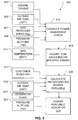
- calculation unit 307 calculates instantaneous power required (PR) in a PR calculation 401.
- PR is visually depicted to the pilot with PR indicator 311 on power gauge 315.
- PR calculation 401 includes a step 403 for calculating the take-off weight of rotorcraft 101.
- the pilot simply calculates the take-off weight of rotorcraft 101 by adding the fuel weight, passenger/cargo weight, and any other weight contributing articles. The pilot then inputs the rotorcraft take-off weight via data input device 319.
- a landing gear sensor automatically calculates the take-off weight and sends the data to calculation unit 307.
- PR calculation 401 is configured so that if the pilot does not enter a rotorcraft weight at take-off, then the rotorcraft's maximum gross weight is used as the default.
- Power safety system 301 is configured to communicate a message on display 305 reminding the pilot to enter and/or verify rotorcraft weight prior to take-off. For example, if a pilot briefly lands rotorcraft 101 to take-on two additional passengers without shutting down, then a weight-on-gear-sensor informs power safety system 301 that the rotorcraft has landed, thereby instigating a message on display 305 for the pilot to enter the new rotorcraft weight prior to take-off.
- a step 405 includes accounting for any change of in the weight of fuel in rotorcraft 101. For example, as the rotorcraft burns fuel during operation, step 405 includes accounting for changing the current rotorcraft weight in accordance with the amount of fuel consumed. The weight of the burned fuel may be calculated by various means, such as a fuel flow measuring device, or by simply accounting for changes in the fuel tank gauge.
- a step 407 includes accounting for changes in a cargo hook load. Some rotorcraft may include a cargo hook for supporting external loads. As such, a load cell device may be used to measure changes in the cargo hook load. Other sensors and devices may be used to account for changes to the rotorcraft weight during operation.
- step 406 includes accounting for any other changes to the weight of the rotorcraft.
- step 406 includes the pilot manually inputting any known change to the weight of the rotorcraft. For example, if the pilot knows he has just lost 500 pounds during flight (paratroopers, cargo drop, etc.), then step 406 includes the pilot accounting for the weight change with an entry with data input device 319.
- Step 406 also includes automatically accounting for any changes to the rotorcraft weight when such a weight changing activity is measured or accounted for by any sensor 309.
- a step 409 represents the real time weight of the rotorcraft during operation, after accounting for weight changes during operation of rotorcraft 101. As the weight of the rotorcraft decreases, the power required to operate the rotorcraft at hover also decreases. If the weight of the rotorcraft increases during operation (via cargo hook for example), then the power required to operate the rotorcraft at hover also increases.
- a step 411 includes continuously measuring outside air temperature (OAT) with an OAT probe, or other temperature measuring device.
- OAT affects the power required to operate the rotorcraft at a hover. For example, generally air at a higher OAT is less dense than air at a lower OAT, for a given altitude.
- the PR to operate the rotorcraft at hover is a function of OAT.
- OAT may influence PR due to main rotor blade tip Mach effects.
- the effect of OAT on PR is preferably determined using a look-up table in calculation unit 307.
- rotorcraft specific performance data correlating OAT to PR is stored in a look-up table data format within calculation unit 307, or other data storage device operably associated with calculation unit 307.
- OAT measured data may be used to calculate PR using rotorcraft performance equations.
- a step 413 includes continuously calculating the pressure altitude (Hp), which is the air pressure at a particular altitude.
- Hp affects the power required to operate the rotorcraft at a hover in part because air at a higher pressure is more compressed and denser, than air at a lower pressure.
- the PR to operate the rotorcraft at hover is a function of Hp.
- the effect of Hp on PR is preferably determined using a look-up table in calculation unit 307.
- rotorcraft specific performance data correlating Hp to PR is stored in a look-up table data format within calculation unit 307, or other data storage device operably associated with calculation unit 307.
- Hp measured data may be used to calculate PR using rotorcraft performance equations.
- wind speed may be measured at a hover site.
- the measured wind speed data can be communicated to the pilot for manual entry via data input device 319.
- instrumentation at a landing site may measure wind speed and communicate that to the pilot via VHF radio communication.
- the pilot may enter the wind speed data via data input device 319.
- a real-time outside air velocity measured relative to the rotorcraft, may be determined by a low air velocity sensor on the rotorcraft, the outside air velocity data being automatically sent to calculation unit 307.
- the pilot may input the outside air velocity data into calculation unit 307.
- the effect of outside air velocity on PR is calculated in calculation unit 307.
- System 301 may be configured such that outside air velocity data is used in the calculation of PR only if the outside air velocity exceeds a minimum threshold. For example, a minimum threshold of a 10 knot outside air velocity may be used.
- a step 421 includes processing the data recorded in steps 409, 411, and 413 using rotorcraft hover performance data to derive real-time PR in a step 423.
- Hover performance data is stored in calculation unit 307.
- PR may be derived for at least an in-ground effect (IGE) hover or out-of-ground effect (OGE) hover.
- IGE in-ground effect
- OGE out-of-ground effect
- IGE hover includes a rotorcraft hover performed at a certain distance to the ground.
- the IGE distance is typically defined by a rotorcraft manufacturer as a hover where the landing gear is a within a certain distance to the ground. IGE hover requires less power than OGE due to ground effect influences associated with the downwash of the rotor blades causing a high pressure area between the rotor blades and the ground.
- the power safety instrument 303 includes a toggle or other input device so that the pilot may dictate that the PR be calculated based upon IGE or OGE. Alternatively, IGE or OGE may be automatically determined by one or more sensors 309 on the rotorcraft 101. It should be appreciated that certain landing site conditions may negate ground effect influences upon hover, such as hovering above long grass or water. As such, system 301 is configured so that the pilot can dictate PR to be calculated based upon IGE or OGE.
- power safety instrument 303 may be configured to graphically communicate to the pilot that PR indicator 311 is being calculated based on IGE hover or OGE hover.
- PR indicator 311 may have a "I" character associated with PR indicator 311 to communicate to the pilot that PR is currently being calculated based upon a IGE hover.
- PR indicator 311 may have an "O" character associated with PR indicator 311 to communicate to the pilot that PR is currently being calculated based upon an OGE hover.
- power safety system 301 is configured to default to OGE since it requires more power to perform an OGE hover than an IGE hover. As such, if the rotorcraft has enough power to perform an OGE hover, then it has enough power to perform an IGE hover.
- An example of an IGE hover is taking off or landing at a helipad.
- An example of an OGE hover is a logging rotorcraft hovering above a tree line waiting for ground personnel to connect a sling load of lumber, the hovering distance being such that PR is calculated using OGE.
- Rotorcraft hover performance data is typically supplied by the rotorcraft manufacturer in a graphic chart format.
- Power safety system 301 preferably includes the mathematical relationships of the rotorcraft hover performance data in electronic format so that a computer processor in calculation unit 307 may calculate PR based upon the real time data collection in steps 409, 411, and 413.
- Step 423 represents the real time calculation of PR.
- the real time calculation of PR is graphical displayed on power safety instrument 303 via PR indicator 311.
- a step 415 includes a weight-altitude-temperature (WAT) calculation.
- the WAT calculation is compared to a WAT limit associated with the rotorcraft.
- the WAT limit of the rotorcraft represents an aircraft limitation at a certain combination of aircraft weight, altitude, and OAT.
- Step 415 includes calculating the WAT calculation by analyzing the real time data acquired in steps 409, 411, and 413. If the WAT calculation is below the rotorcraft WAT limit, then the WAT calculation does not produce a limitation, as depicted in step 419. However, if the WAT calculation is equal to or above the rotorcraft WAT limit, then the WAT calculation does produce a limitation, as depicted in step 417.
- PR indicator 311 changes size, shape, or color so that the pilot knows that if he or she attempts to perform a hover at the current weight/altitude/OAT, then the WAT limit will be exceeded, possibly causing loss of aircraft control during the attempt to perform the hover.
- the aforementioned transformation of PR indicator 311 prevents the pilot from incorrectly thinking it is safe to perform a hover, take-off, or landing, even though power safety instrument 303 may depict sufficient margin between PA indicator 313 and PR indicator 311.
- calculation unit 307 calculates instantaneous power available (PA) in a PA calculation 501.
- PA is visually depicted to the pilot with PA indicator 313 on power gauge 315.
- PA calculation 501 includes a step 513 for conducting a power assurance check of the engine(s) of rotorcraft 101.
- Conducting a power assurance check in step 513 includes acquiring data from one or more sensors 309 in order to evaluate the health and performance of the engine.
- a power assurance check may be conducted to verify the engine is able to meet minimum requirements.
- the power assurance check may be conducted to quantity performance of the engine.
- rotorcraft engine(s) are initially delivered above "min-spec", meaning the performance of the engine provides more power available than is stated in the rotorcraft specification and power available charts. For example, if an engine is 6% above min-spec, then the engine has approximately 6% more power available than a min-spec engine, at the same ambient conditions. However, unless the pilot is able to account for the 6% above min-spec power, the pilot isn't able to confidently take advantage of the above min-spec power available during flight operations. It should also be appreciated that engine performance may degrade over time, thus it is important for the pilot to be able to account for engine degradation in order to continue safe operation of the rotorcraft.
- a step 503 includes measuring the torque produced by the engine in the rotorcraft.
- a step 505 includes measuring the OAT which affects the power produced by the engine.
- a step 507 includes measuring the gas producer speed (Ng) of the engine.
- a step 509 includes measuring the pressure altitude (Hp), which affects the power produced by the engine.
- a step 511 includes measuring the gas temperature (MGT), which affects the power produced by the engine. It should be appreciated that any combination of measurements may be taken in order to conduct the power assurance check in step 513, including measurements other than depicted in steps 503, 505, 507, 509, and 511.
- the power assurance check of step 513 is performed periodically, such as in a hover or forward flight procedure.
- the power assurance check of step 513 may also be performed during a pre-flight procedure.
- the power assurance check of step 513 may be conducted by the pilot, or it may occur autonomously without requiring pilot interaction.
- calculation unit 307 records a rolling average of the most recent power assurance checks.
- the result of the ten most recent power assurance checks may be averaged to derive a power assurance calculation.
- the power assurance check of step 513 may simply provide a pass/fail result, a passing result meaning that the engine meets the requirements of a min-spec engine.
- a step 515 includes interpreting the power assurance data from step 513 in order to determine the performance of the engine in terms of a percentage above or below min-spec.
- power assurance data from step 513 is compared with min-spec engine power, thus arriving at percentage above or below min-spec power.
- the power assurance check from step 513 only provides a pass/fail determination, such that step 515 includes determining a percentage above or below min-spec engine based upon an input from the pilot. For example, if the pilot knows the rotorcraft has a +10% engine (10% above min-spec), then the pilot enters that into power safety system 301 via data input device 319.
- step 515 may be autonomously performed by calculation unit 307, or manually entered by the pilot.
- step 515 also includes accounting for any rotorcraft propulsion configuration which may affect engine performance.
- an air inlet configuration on the rotorcraft may increase or decrease power available.
- an air inlet configuration may include a standard inlet, a particle separator inlet, inlet barrier filter, and snow baffles, to name a few.
- a particular inlet configuration may correlate to particular performance data to be used in the calculation of PA in step 525. Therefore, step 515 includes the ability for the pilot to enter information, with data input device 319, regarding a configuration (such as air inlet configuration) that in turn may dictate particular performance data used in the calculation of PA by calculation unit 307.
- a step 525 includes calculating instantaneous PA based upon the above/below min-spec engine determination from step 515, as well as a plurality of instantaneous measurements from sensors 309.
- a step 517 includes measuring engine bleed air being drawn from the engine. The measurement of engine bleed air usage may include simply determining if the engine bleed air switch is on or off. Alternatively, the measurement of engine bleed air may include taking one or more measurements to quantify an amount of bleed air being drawn from the engine. Engine bleed air acts as a drain on engine PA, as such, if engine bleed air is turned off, then PA increases.
- a step 519 includes measuring OAT, which has an effect on PA.
- a step 521 includes measuring the generator load on the engine, which affects PA.
- a step 523 includes measuring the Hp, which similar to OAT, has an effect on PA. It should be appreciated that any combination of measurements may be taken in order to conduct the PA calculation in step 525, including measurements other than depicted in steps 517, 519, 521, and 523.
- the instantaneous calculation of PA in step 525 is graphical displayed on power safety instrument 303 via PA indicator 313.
- the PA calculated in step 525 is limited by any rotorcraft limitation.
- PA is limited by a transmission torque limit.
- PA indicator 313 preferably does not exceed the transmission torque limit. Therefore, the pilot can trust that the position of PA indicator 313 is the absolute PA.
- PA indicator 313 includes a graphic to communicate to the pilot that the PA indicator 313 position is being limited by the transmission torque limit, or other rotorcraft limitation. For example, if the PA indicator 313 is being limited by the transmission torque limit, then "T" is displayed in the PA indicator 313.
- PA indicator 313 is not restricted by the transmission torque limit, or other rotorcraft limitation.
- step 525 may also be configured to process data in order to calculate PA for an emergency landing maneuver upon the loss of an engine.
- PA indicator 313 may be configured to represent the PA for the rotorcraft to perform an emergency landing maneuver in a one-engine-inoperable (OEI) condition.
- OEI one-engine-inoperable
- the pilot is able to look at power safety instrument 303 and determine if there is sufficient margin between the PR indicator 311 and PA indicator 313 in order to perform an emergency landing maneuver at the current atmosphere conditions and rotorcraft configuration with OEI.
- power gauge 315 may be configured so that PA indicator 313 visually forecast the PA at certain engine levels. For example, if an engine is only able to operate 30 seconds at an extremely high level, then the PA indicator 313 may visually communicate that the PA indicator position will decrease after the 30 second time period expires. The operable engine may then be able to run at a decreased level for two minutes after the expiration of the 30 second time limit. Therefore, the PA indicator 313 would move accordingly, then visually communicate that the current PA indicator position is valid for the next two minutes. This process may continue if the engine is operating at a PA that is sustainable.
- Such a feature of system 301 allows the pilot to quickly ascertain margin between PR and PA during an OEI condition for an multi-engine rotorcraft.
- power safety system 301 provides for efficient and safe operation of rotorcraft 101.
- power safety system 301 orients the pilot in real-time so that the pilot can quickly and accurately ascertain whether a hover landing or take-off is achievable.
- power safety system 301 continuously displays PR and PA at the current rotorcraft location so that the pilot, by observing the positions of PR indicator 311 and PA indicator 313, may ascertain whether it is safe to perform a hover at any time during the flight.
- Power safety system 301 also provides the ability of the pilot to make changes to the weight of the aircraft in order to produce sufficient margin between PR and PA to achieve the hover.
- a non-limiting example is the pilot burning fuel for an extra 30 minutes for the sole reason of reducing aircraft weight. Because PR and PA are calculated in real-time, the pilot is able to burn just enough surplus fuel as required to result in sufficient margin between PR and PA for the desired hover.
- the following non-limiting simplified flight scenario is provided to illustrate power safety system 301 in operation.
- a rotorcraft pilot is tasked with performing a search- and-rescue (SAR) mission for a mountain climber.
- the pilot only has a general idea of the area where the mountain climber may be located. Because the pilot does not know the future hover location, the pilot is unable to make an accurate pre-flight calculation regarding whether the rotorcraft is able to perform a hover at the unknown location.
- the rotorcraft is equipped with power safety system 301. After, the pilot locates the mountain climber and a landing area, the pilot simply flies over the hover site while maintaining a sufficient forward speed. Power safety system 301 records and processes data necessary to calculate PA and PR to perform a hover at the site.
- the pilot may also enter the mountain climber's weight into power safety system 301 via data input device 319.
- the pilot looks at power safety instrument 303 and ascertains that there is sufficient margin between PR indicator 311 and PA indicator 313 to perform the hover.
- the pilot then slows the rotorcraft to a hover and safely performs the hover at the hover site.
- Power safety system 301 is preferably configured to operate in a flight planning mode, in addition to real-time flight mode. Flight planning mode allows the pilot to predict PA and PR at a future hover location. Power safety system 301 may be operated in flight planning mode either pre-flight or during a flight. When power safety system 301 is being operated in a flight planning mode during a flight, power safety instrument 303 preferably communicates to the pilot that power safety system 301 is being operated in a flight planning mode so that the pilot does not mistake the positions of PR indicator 311 and PA indicator 313 as being real-time flight positions. Flight planning mode operation of power safety system 301 involves the pilot manually entering a predicted rotorcraft weight, pressure altitude (Hp), and outside air temperature (OAT), at the desired hover location.
- Hp pressure altitude
- OAT outside air temperature
- OAT and Hp may be substituted with a density altitude measurement.
- the pilot may be made aware of hover site conditions through wireless communication, such as VHF radio, from instrumentation at a landing site.
- Hp and OAT at the desired hover site may be automatically communicated to power safety system 301 via wireless data transfer, such as telemetry or the like.
- power safety system 301 may automatically acquire the Hp and OAT data such that the pilot only has to enter a predicted aircraft weight.
- Operation of power safety system 301 in flight planning mode prevents pilot errors associated with trying to read small paper charts.
- operation of power safety system 301 in flight planning mode allows the rotorcraft to be more fully utilized by performing the calculations of PA and PR to a high level of accuracy.
- the flight planning mode is also configured for determining a maximum allowable weight of the rotorcraft while having sufficient margin between PA and PR at hover. In such a situation, the pilot enters a desirable amount of margin between PA and PR, and enters the necessary data.
- System 301 calculates a maximum weight of the rotorcraft and displays that amount to the pilot on display 305.
- margin between the PA and PR may be communicated to the pilot in terms of weight margin.
- display 305 may include a graphic of margin between PA and PR quantified in terms of weight margin, the weight margin being the extra amount of weight the rotorcraft could be carrying while still having sufficient PA to meet the PR to hover.
- Certain pilots may desire to comprehend margin between PA and PR in terms of weight, instead of visually observing a distance between PR indicator 311 and PA indicator 313.
- the system of the present application provides significant advantages, including: (1) providing a pilot real-time data during rotorcraft operation for deciding whether it is safe to perform a hover; (2) allowing a pilot to maximize rotorcraft payload; (3) allowing a pilot to operate a rotorcraft without having to perform pre-flight hover calculations; (4) allowing a pilot to determine a hover site while operating the rotorcraft; (5) providing a flight planning tool that accurately calculates predicted power available and power required for a predicted hover; (6) providing a tool that safely determines an amount of weight a rotorcraft can carry while still having sufficient margin between PR and PA at the hover site, (7) reducing potential for pilot error; and (8) improving efficiency and safety of the rotorcraft.
Landscapes
- Engineering & Computer Science (AREA)
- Aviation & Aerospace Engineering (AREA)
- Mechanical Engineering (AREA)
- Physics & Mathematics (AREA)
- General Physics & Mathematics (AREA)
- Radar, Positioning & Navigation (AREA)
- Remote Sensing (AREA)
- Testing Of Devices, Machine Parts, Or Other Structures Thereof (AREA)
- Arrangements For Transmission Of Measured Signals (AREA)
Claims (11)
- Verfahren zum Bereitstellen von Leistungsinformationen in einem Drehflügler, wobei der Drehflügler eine Leistungsquelle aufweist und das Verfahren Folgendes umfasst:Berechnen einer erforderlichen Echtzeitleistung durch eine Berechnungseinheit, was Folgendes umfasst:Aufzeichnen von Daten, die einer Variablen zugeordnet sind, wobei die Variable mindestens eine der folgenden ist:ein Echtzeit-Gewicht des Drehflüglers, eine Echtzeit-Außenlufttemperatur, eine Echtzeit-Druckhöhe;unter Standardbedingungen, Verarbeiten der Daten unter Verwendung von Schwebeleistungsfähigkeitsinformationen basierend auf Leistungsfähigkeitsdaten außerhalb des Bodeneffekts (OGE-Leistungsfähigkeitsdaten); undErmöglichen, dass ein Anwender der Berechnungseinheit befehlen kann, die Daten unter Verwendung von Schwebeleistungsfähigkeitsinformationen basierend auf Leistungsfähigkeitsdaten bei Bodeneffekt (IGE-Leistungsfähigkeitsdaten) zu verarbeiten;Berechnen einer verfügbaren Echtzeit-Leistung, was umfasst:Durchführen einer Leistungssicherungsprüfung, die zu Leistungssicherungsdaten führt;Bestimmen eines Betrags, um den die Leistungsquelle über oder unter Minimalspezifikationskriterien liegt;Aufzeichnen von Informationen, die einer Messung einer Variablen zugeordnet sind, die die verfügbare Leistung beeinflusst; undVerarbeiten der Informationen unter Verwendung von Leistungsquellen-Leistungsfähigkeitsinformationen;Ausrichten eines Anzeigers für erforderliche Leistung auf einem Leistungssicherheitsinstrument, wobei die Position des Anzeigers für erforderliche Leistung von der Berechnung der erforderlichen Leistung abhängt; undAusrichtung eines Anzeigers für verfügbare Leistung auf einem Leistungssicherheitsinstrument, wobei die Position des für verfügbare Leistung von der Berechnung der verfügbaren Leistung abhängig ist.
- Verfahren nach Anspruch 1, das ferner Folgendes umfasst:Ausrichten einer Leistungsnutzungsnadel auf dem Leistungssicherheitsinstrument, wobei eine Position der Leistungsnutzungsnadel die Leistung, die aktuell durch den Drehflügler genutzt wird, angibt.
- Verfahren nach Anspruch 1, wobei das Ausrichten eines Anzeigers für verfügbare Leistung basierend darauf, dass die erforderliche Leistung über einer WAT-Grenze liegt, eingeschränkt ist.
- Verfahren nach Anspruch 1, wobei die Messung mindestens einen der folgenden Parameter betrifft: einen aktuellen Triebwerks-Zapfluftverbrauch, eine aktuelle Außenlufttemperatur, einen Generatorlastbetrag und eine aktuelle Druckhöhe.
- Leistungssicherheitssystem, das dazu ausgelegt ist, Leistungsinformationen in einem Drehflügler bereitzustellen, wobei der Drehflügler ein Triebwerk umfasst und das Leistungssicherheitssystem Folgendes umfasst:ein Leistungssicherheitsinstrument, das Folgendes umfasst:einen Anzeiger für erforderliche Leistung, der auf einer Anzeige angeordnet ist, wobei der Anzeiger für erforderliche Leistung dazu ausgelegt ist, eine Leistung zu vermitteln, die erforderlich ist, um den Drehflügler in einem Schwebeflugmodus zu betreiben;einen Anzeiger für verfügbare Leistung, der auf einer Anzeige angeordnet ist, wobei der Anzeiger für verfügbare Leistung dazu ausgelegt ist, eine Leistung zu vermitteln, die während des Schwebeflugmodus aus der Leistungsquelle in dem Drehflügler verfügbar ist;mindestens einen Sensor, der dazu ausgelegt ist, mindestens eine Variable zu messen, die eine Auswirkung auf die erforderliche Leistung und die verfügbare Leistung hat;mindestens eine Dateneingabevorrichtung; undeine Berechnungseinheit zum Berechnen der Leistung, die erforderlich ist, um den Drehflügler in einem Schwebeflugmodus zu betreiben, wobei die Berechnungseinheit dazu ausgelegt ist, die erforderliche Leistung basierend auf Leistungsfähigkeitsdaten außerhalb des Bodeneffekts (OGE-Leistungsfähigkeitsdaten) zu berechnen;wobei die Dateneingabevorrichtung dazu ausgelegt ist, es einem Anwender zu ermöglichen, der Berechnungseinheit zu befehlen, Leistungsfähigkeitsdaten bei Bodeneffekt (IGE-Leistungsfähigkeitsdaten) zum Berechnen der Leistung, die erforderlich ist, um das Flugzeug in dem Schwebeflugmodus zu betreiben, zu verwenden.
- Leistungssicherheitssystem nach Anspruch 5, wobei die erforderliche Leistung basierend auf einer Messung mehrerer Variablen zu einem Zeitpunkt berechnet wird, wobei der Anzeiger für erforderliche Leistung dazu ausgelegt ist, grafisch den Betrag an Leistung anzuzeigen, die erforderlich ist, um den Schwebeflugmodus ungefähr zu dem gleichen Zeitpunkt durchzuführen.
- Leistungssicherheitssystem nach Anspruch 5, wobei die verfügbare Leistung basierend auf einer Messung mehrerer Variablen zu einem Zeitpunkt berechnet wird, wobei der Anzeiger für verfügbare Leistung dazu ausgelegt ist, grafisch den Betrag an Leistung anzuzeigen, die verfügbar ist, um den Schwebeflugmodus ungefähr zu dem gleichen Zeitpunkt durchzuführen.
- Leistungssicherheitssystem nach Anspruch 5, wobei das Leistungssicherheitsinstrument dazu ausgelegt ist, in einem Flugplanungsmodus derart zu arbeiten, dass eine Position des Anzeigers für erforderliche Leistung eine vorhergesagte Leistung darstellt, die erforderlich ist, damit der Drehflügler ein vorhergesagtes Schwebemanöver durchführt, und eine Position des Anzeigers für verfügbare Leistung eine vorhergesagte Leistung darstellt, die in dem Drehflügler während des vorhergesagten Schwebemanövers aus der Leistungsquelle verfügbar ist.
- Leistungssicherheitssystem nach Anspruch 5, wobei eine Spanne zwischen einer ersten Position des Anzeigers für erforderliche Leistung und einer zweiten Position des Anzeigers für verfügbare Leistung eine überschüssige Leistung darstellt, die verfügbar ist, um den Schwebeflugmodus durchzuführen.
- Leistungssicherheitssystem nach Anspruch 5, wobei eine Position des Anzeigers für erforderliche Leistung durch eine WAT-Grenze eingeschränkt ist.
- Leistungssicherheitssystem nach Anspruch 5, wobei eine Position des Anzeigers für verfügbare Leistung durch eine Übertragungsdrehmomentgrenze eingeschränkt ist.
Priority Applications (2)
| Application Number | Priority Date | Filing Date | Title |
|---|---|---|---|
| EP17191651.3A EP3309079B1 (de) | 2010-12-22 | 2010-12-22 | Leistungssicherheitsinstrumentsystem |
| EP16180840.7A EP3124385B1 (de) | 2010-12-22 | 2010-12-22 | Stromsicherheitssystem |
Applications Claiming Priority (4)
| Application Number | Priority Date | Filing Date | Title |
|---|---|---|---|
| EP15174684.9A EP2985226B1 (de) | 2010-12-22 | 2010-12-22 | Leistungssicherheitsinstrument |
| PCT/US2010/061701 WO2012087303A1 (en) | 2010-12-22 | 2010-12-22 | Power safety instrument system |
| EP16180840.7A EP3124385B1 (de) | 2010-12-22 | 2010-12-22 | Stromsicherheitssystem |
| EP10861026.2A EP2635874B1 (de) | 2010-12-22 | 2010-12-22 | Leistungssicherheitsinstrument |
Related Parent Applications (3)
| Application Number | Title | Priority Date | Filing Date |
|---|---|---|---|
| EP15174684.9A Division EP2985226B1 (de) | 2010-12-22 | 2010-12-22 | Leistungssicherheitsinstrument |
| EP15174684.9A Division-Into EP2985226B1 (de) | 2010-12-22 | 2010-12-22 | Leistungssicherheitsinstrument |
| EP10861026.2A Division EP2635874B1 (de) | 2010-12-22 | 2010-12-22 | Leistungssicherheitsinstrument |
Related Child Applications (2)
| Application Number | Title | Priority Date | Filing Date |
|---|---|---|---|
| EP17191651.3A Division-Into EP3309079B1 (de) | 2010-12-22 | 2010-12-22 | Leistungssicherheitsinstrumentsystem |
| EP17191651.3A Division EP3309079B1 (de) | 2010-12-22 | 2010-12-22 | Leistungssicherheitsinstrumentsystem |
Publications (2)
| Publication Number | Publication Date |
|---|---|
| EP3124385A1 EP3124385A1 (de) | 2017-02-01 |
| EP3124385B1 true EP3124385B1 (de) | 2017-10-25 |
Family
ID=46314281
Family Applications (4)
| Application Number | Title | Priority Date | Filing Date |
|---|---|---|---|
| EP17191651.3A Active EP3309079B1 (de) | 2010-12-22 | 2010-12-22 | Leistungssicherheitsinstrumentsystem |
| EP16180840.7A Active EP3124385B1 (de) | 2010-12-22 | 2010-12-22 | Stromsicherheitssystem |
| EP10861026.2A Active EP2635874B1 (de) | 2010-12-22 | 2010-12-22 | Leistungssicherheitsinstrument |
| EP15174684.9A Active EP2985226B1 (de) | 2010-12-22 | 2010-12-22 | Leistungssicherheitsinstrument |
Family Applications Before (1)
| Application Number | Title | Priority Date | Filing Date |
|---|---|---|---|
| EP17191651.3A Active EP3309079B1 (de) | 2010-12-22 | 2010-12-22 | Leistungssicherheitsinstrumentsystem |
Family Applications After (2)
| Application Number | Title | Priority Date | Filing Date |
|---|---|---|---|
| EP10861026.2A Active EP2635874B1 (de) | 2010-12-22 | 2010-12-22 | Leistungssicherheitsinstrument |
| EP15174684.9A Active EP2985226B1 (de) | 2010-12-22 | 2010-12-22 | Leistungssicherheitsinstrument |
Country Status (5)
| Country | Link |
|---|---|
| US (4) | US9035802B2 (de) |
| EP (4) | EP3309079B1 (de) |
| CN (1) | CN103270390B (de) |
| CA (1) | CA2820001C (de) |
| WO (1) | WO2012087303A1 (de) |
Families Citing this family (27)
| Publication number | Priority date | Publication date | Assignee | Title |
|---|---|---|---|---|
| US8626363B2 (en) * | 2007-02-08 | 2014-01-07 | Bell Helicopter Textron Inc. | Aircraft feathering, flapping and rotor loads indicator |
| CA2820001C (en) * | 2010-12-22 | 2016-06-07 | Bell Helicopter Textron Inc. | Power safety instrument system |
| US8825237B2 (en) | 2012-04-26 | 2014-09-02 | Bell Helicopter Textron Inc. | System and method for economic usage of an aircraft |
| US9767701B2 (en) | 2014-06-26 | 2017-09-19 | Amazon Technologies, Inc. | Ground effect based surface sensing in automated aerial vehicles |
| US9547990B2 (en) | 2014-08-21 | 2017-01-17 | Honeywell International Inc. | Rotary-wing aircraft emergency landing control |
| US20170267338A1 (en) | 2014-10-01 | 2017-09-21 | Sikorsky Aircraft Corporation | Acoustic signature variation of aircraft utilizing a clutch |
| US9731837B2 (en) | 2015-02-17 | 2017-08-15 | Honeywell International Inc. | Servo transparency warning system and method |
| US10766631B2 (en) * | 2015-05-27 | 2020-09-08 | Textron Innovations Inc. | Multiple power assurance check procedure for aircraft with an engine inlet barrier filter installed |
| DE102015214319A1 (de) * | 2015-07-29 | 2017-02-02 | Robert Bosch Gmbh | Vorrichtung und Verfahren zum Eingeben und Anzeigen von Werten sowie entsprechendes System |
| US9828087B2 (en) | 2016-01-27 | 2017-11-28 | Honeywell International Inc. | Systems and methods for ground effect ceiling limit display |
| US10223846B2 (en) * | 2016-10-10 | 2019-03-05 | General Electric Company | Aerial vehicle engine health prediction |
| US10977880B2 (en) * | 2017-05-31 | 2021-04-13 | General Electric Company | Hover time remaining for an aircraft |
| EP3477261B1 (de) * | 2017-10-26 | 2020-02-26 | Bell Helicopter Textron Inc. | Fluginstrumentwarnanzeige |
| US11085321B2 (en) | 2018-01-30 | 2021-08-10 | Honeywell International Inc. | Bleed air compensated continuous power assurance analysis system and method |
| US10173787B1 (en) | 2018-02-12 | 2019-01-08 | Bell Helicopter Textron Inc. | Rotor speed indication systems for rotorcraft |
| US10640230B2 (en) * | 2018-04-04 | 2020-05-05 | Jurgen R. Ihns | Cockpit pressurization and oxygen warning system |
| FR3084057B1 (fr) | 2018-07-17 | 2020-06-19 | Airbus Helicopters | Procede et dispositif de determination predictive de parametres caractaristiques du fonctionnement d'un aeronef a voilure tournante pour la realisation d'une manoeuvre predeterminee |
| US10933980B2 (en) * | 2018-08-03 | 2021-03-02 | Bell Helicopter Textron Inc. | Peak power use with pilot monitoring |
| US11202683B2 (en) | 2019-02-22 | 2021-12-21 | Auris Health, Inc. | Surgical platform with motorized arms for adjustable arm supports |
| FR3095196B1 (fr) * | 2019-04-17 | 2021-12-03 | Airbus Helicopters | Procédé et dispositif pour estimer la santé d’une installation motrice d’un aéronef pourvu d’au moins un moteur et d’un filtre colmatable filtrant de l’air en amont du moteur |
| US11663863B2 (en) * | 2019-06-07 | 2023-05-30 | Pratt & Whitney Canada Corp. | Methods and systems for operating a rotorcraft |
| US11577828B2 (en) * | 2020-04-30 | 2023-02-14 | Lockheed Martin Corporation | Power display for compound aircraft using shared engine torque |
| USD940193S1 (en) | 2020-04-30 | 2022-01-04 | Lockheed Martin Corporation | Flight display screen or portion thereof including a power indicator icon |
| USD1117211S1 (en) * | 2020-09-04 | 2026-03-10 | Teledyne Flir Defense, Inc. | Display screen or portion thereof with graphical user interface |
| CA3194388A1 (en) | 2022-03-30 | 2023-09-30 | Taiga Motors Inc. | Power indicator for electric vehicle |
| US12208917B2 (en) | 2022-06-28 | 2025-01-28 | Beta Air, Llc | Transition gauge for electric aircraft |
| CN115743574A (zh) * | 2022-11-17 | 2023-03-07 | 中国直升机设计研究所 | 一种直升机发动机功率限制系统 |
Family Cites Families (18)
| Publication number | Priority date | Publication date | Assignee | Title |
|---|---|---|---|---|
| US3616691A (en) * | 1969-03-26 | 1971-11-02 | Bendix Corp | Mission capability indicating system |
| US3754440A (en) * | 1972-08-16 | 1973-08-28 | Us Navy | Helicopter lift margin determining system |
| US4034605A (en) * | 1975-09-26 | 1977-07-12 | Pacer Systems Inc. | Maneuver margin presenting |
| US4736331A (en) * | 1982-05-26 | 1988-04-05 | United Technologies Corporation | Helicopter power available to hover indicator |
| CA1331812C (en) * | 1988-02-24 | 1994-08-30 | Bruce E. Hamilton | Aircraft helmet pointing angle display symbology |
| US5150117A (en) * | 1991-04-22 | 1992-09-22 | United Technologies Corporation | Power management symbology display system |
| FR2749545B1 (fr) * | 1996-06-07 | 1998-08-07 | Eurocopter France | Indicateur de pilotage pour aeronef |
| US7212942B2 (en) * | 2003-06-10 | 2007-05-01 | Precision Innovations Llc | Power available and limitation indicator for use with an aircraft engine |
| US7072772B2 (en) | 2003-06-12 | 2006-07-04 | Predicant Bioscience, Inc. | Method and apparatus for modeling mass spectrometer lineshapes |
| US7975465B2 (en) * | 2003-10-27 | 2011-07-12 | United Technologies Corporation | Hybrid engine accessory power system |
| US7414544B2 (en) * | 2005-01-28 | 2008-08-19 | Bell Helicopter Textron, Inc. | Power situation indicator |
| FR2888638B1 (fr) * | 2005-07-18 | 2007-09-28 | Airbus Sas | Indicateur de pilotage pour un aeronef, destine a fournir un parametre de puissance d'au moins un turbopropulseur dudit aeronef |
| CN1782353A (zh) * | 2005-09-08 | 2006-06-07 | 辛宪武 | 燃料供给监测系统 |
| US7679529B2 (en) * | 2006-12-07 | 2010-03-16 | The Boeing Company | Method and apparatus for indicating operational state of aircraft engine |
| US9091545B2 (en) | 2007-11-27 | 2015-07-28 | Florida Institute For Human And Machine Cognition, Inc. | Motion-resolving hover display |
| US7801695B2 (en) * | 2008-12-23 | 2010-09-21 | Honeywell International Inc. | Operations support systems and methods with model-based torque estimates |
| CA2820001C (en) * | 2010-12-22 | 2016-06-07 | Bell Helicopter Textron Inc. | Power safety instrument system |
| US20150130644A1 (en) * | 2013-11-13 | 2015-05-14 | Taylor L. Kiel | Lighting systems for landing in a degraded visual environment |
-
2010
- 2010-12-22 CA CA2820001A patent/CA2820001C/en active Active
- 2010-12-22 EP EP17191651.3A patent/EP3309079B1/de active Active
- 2010-12-22 WO PCT/US2010/061701 patent/WO2012087303A1/en not_active Ceased
- 2010-12-22 EP EP16180840.7A patent/EP3124385B1/de active Active
- 2010-12-22 CN CN201080070916.4A patent/CN103270390B/zh not_active Expired - Fee Related
- 2010-12-22 US US13/641,325 patent/US9035802B2/en active Active
- 2010-12-22 EP EP10861026.2A patent/EP2635874B1/de active Active
- 2010-12-22 EP EP15174684.9A patent/EP2985226B1/de active Active
-
2015
- 2015-05-18 US US14/715,236 patent/US9352849B2/en active Active
-
2016
- 2016-05-31 US US15/168,356 patent/US9663243B2/en active Active
-
2017
- 2017-05-30 US US15/608,696 patent/US10145708B2/en active Active
Non-Patent Citations (1)
| Title |
|---|
| None * |
Also Published As
| Publication number | Publication date |
|---|---|
| US20130120165A1 (en) | 2013-05-16 |
| CN103270390B (zh) | 2016-09-28 |
| CA2820001C (en) | 2016-06-07 |
| EP3309079A1 (de) | 2018-04-18 |
| US20160272342A1 (en) | 2016-09-22 |
| CA2820001A1 (en) | 2012-06-28 |
| WO2012087303A1 (en) | 2012-06-28 |
| EP2635874A1 (de) | 2013-09-11 |
| CN103270390A (zh) | 2013-08-28 |
| EP2985226A1 (de) | 2016-02-17 |
| EP2985226B1 (de) | 2016-11-09 |
| EP2635874A4 (de) | 2014-06-25 |
| EP3309079B1 (de) | 2019-08-07 |
| US10145708B2 (en) | 2018-12-04 |
| US20170307401A1 (en) | 2017-10-26 |
| US9035802B2 (en) | 2015-05-19 |
| US9352849B2 (en) | 2016-05-31 |
| EP3124385A1 (de) | 2017-02-01 |
| US9663243B2 (en) | 2017-05-30 |
| EP2635874B1 (de) | 2015-07-01 |
| US20150321769A1 (en) | 2015-11-12 |
Similar Documents
| Publication | Publication Date | Title |
|---|---|---|
| US10145708B2 (en) | Power safety instrument system | |
| US7031812B1 (en) | System and method for monitoring aircraft engine health and determining engine power available, and applications thereof | |
| EP2461142B1 (de) | Verfahren und System zur Berechnung des Abfluggewichts eines Flugzeugs | |
| US9536358B2 (en) | Method and a device for determining and optimizing parameters that are characteristic of the operation of a rotary wing aircraft | |
| US10545047B2 (en) | Method of estimating the instantaneous mass of a rotary wing aircraft | |
| CN108883824A (zh) | 飞行器的数据的获取、处理及飞行状况监控的方法及系统 | |
| WO2005120954A9 (en) | System and method for monitoring aircraft engine health and determining engine power available, and applications thereof | |
| EP4190698B1 (de) | Steuereinheit und anzeigevorrichtung für ein schwebefähiges flugzeug oder für ein flugsimulationssystem eines solchen flugzeugs und entsprechendes verfahren zur unterstützung bei der durchführung eines manövers | |
| CN115477018B (zh) | 通过从电动力设备提供机械动力来辅助在高空驾驶旋翼飞行器的方法 | |
| US7143003B2 (en) | Pilot indicator for predicting changes in the monitoring parameters of a gas turbine engine | |
| RU2631557C1 (ru) | Способ определения в полете изгибных напряжений на валу несущего винта вертолета с торсионной втулкой несущего винта | |
| Mantay et al. | Helicopter response to an airplane's trailing vortex | |
| Deiler et al. | Longitudinal Trim Analysis for Aircraft Icing From the SENS4ICE European Flight Test Campaign | |
| Buckanin et al. | Rotor system evaluation. Phase 1 | |
| de Paula et al. | Development of New Flight Test Techniques for Helicopter Air to Air Refueling Qualification Process | |
| Vorst et al. | Korean-Dutch Cooperation for the KA32 Helicopter Training Simulator Flight Mechanics Model Development | |
| Faulkner et al. | Handling qualities and flight performance: implications of the | |
| Vorst et al. | Flight mechanics model development for a ka32 training simulator | |
| Picasso et al. | Airworthiness and Flight Characteristics Test. Part 2. YAH-64 Advanced Attack Helicopter | |
| Dominick et al. | Fuel Conservation Evaluation of US Army Helicopters. Part 6. Performance Calculator Evaluation | |
| Dalton et al. | Exploratory Study of the Operational Conditions of Bell Model 205A-1 in USFS Service |
Legal Events
| Date | Code | Title | Description |
|---|---|---|---|
| PUAI | Public reference made under article 153(3) epc to a published international application that has entered the european phase |
Free format text: ORIGINAL CODE: 0009012 |
|
| 17P | Request for examination filed |
Effective date: 20160722 |
|
| AC | Divisional application: reference to earlier application |
Ref document number: 2985226 Country of ref document: EP Kind code of ref document: P Ref document number: 2635874 Country of ref document: EP Kind code of ref document: P |
|
| AK | Designated contracting states |
Kind code of ref document: A1 Designated state(s): AL AT BE BG CH CY CZ DE DK EE ES FI FR GB GR HR HU IE IS IT LI LT LU LV MC MK MT NL NO PL PT RO RS SE SI SK SM TR |
|
| GRAP | Despatch of communication of intention to grant a patent |
Free format text: ORIGINAL CODE: EPIDOSNIGR1 |
|
| INTG | Intention to grant announced |
Effective date: 20170614 |
|
| RIN1 | Information on inventor provided before grant (corrected) |
Inventor name: MCCOLLOUGH, JAMES Inventor name: OLTHETEN, ERIK Inventor name: LAPPOS, NICHOLAS |
|
| GRAJ | Information related to disapproval of communication of intention to grant by the applicant or resumption of examination proceedings by the epo deleted |
Free format text: ORIGINAL CODE: EPIDOSDIGR1 |
|
| GRAS | Grant fee paid |
Free format text: ORIGINAL CODE: EPIDOSNIGR3 |
|
| GRAA | (expected) grant |
Free format text: ORIGINAL CODE: 0009210 |
|
| INTC | Intention to grant announced (deleted) | ||
| AC | Divisional application: reference to earlier application |
Ref document number: 2985226 Country of ref document: EP Kind code of ref document: P Ref document number: 2635874 Country of ref document: EP Kind code of ref document: P |
|
| AK | Designated contracting states |
Kind code of ref document: B1 Designated state(s): AL AT BE BG CH CY CZ DE DK EE ES FI FR GB GR HR HU IE IS IT LI LT LU LV MC MK MT NL NO PL PT RO RS SE SI SK SM TR |
|
| REG | Reference to a national code |
Ref country code: GB Ref legal event code: FG4D |
|
| REG | Reference to a national code |
Ref country code: CH Ref legal event code: EP |
|
| REG | Reference to a national code |
Ref country code: AT Ref legal event code: REF Ref document number: 939661 Country of ref document: AT Kind code of ref document: T Effective date: 20171115 |
|
| REG | Reference to a national code |
Ref country code: IE Ref legal event code: FG4D |
|
| REG | Reference to a national code |
Ref country code: DE Ref legal event code: R096 Ref document number: 602010046314 Country of ref document: DE |
|
| REG | Reference to a national code |
Ref country code: FR Ref legal event code: PLFP Year of fee payment: 8 |
|
| REG | Reference to a national code |
Ref country code: NL Ref legal event code: MP Effective date: 20171025 |
|
| REG | Reference to a national code |
Ref country code: LT Ref legal event code: MG4D |
|
| REG | Reference to a national code |
Ref country code: AT Ref legal event code: MK05 Ref document number: 939661 Country of ref document: AT Kind code of ref document: T Effective date: 20171025 |
|
| PG25 | Lapsed in a contracting state [announced via postgrant information from national office to epo] |
Ref country code: NL Free format text: LAPSE BECAUSE OF FAILURE TO SUBMIT A TRANSLATION OF THE DESCRIPTION OR TO PAY THE FEE WITHIN THE PRESCRIBED TIME-LIMIT Effective date: 20171025 |
|
| PG25 | Lapsed in a contracting state [announced via postgrant information from national office to epo] |
Ref country code: ES Free format text: LAPSE BECAUSE OF FAILURE TO SUBMIT A TRANSLATION OF THE DESCRIPTION OR TO PAY THE FEE WITHIN THE PRESCRIBED TIME-LIMIT Effective date: 20171025 Ref country code: SE Free format text: LAPSE BECAUSE OF FAILURE TO SUBMIT A TRANSLATION OF THE DESCRIPTION OR TO PAY THE FEE WITHIN THE PRESCRIBED TIME-LIMIT Effective date: 20171025 Ref country code: NO Free format text: LAPSE BECAUSE OF FAILURE TO SUBMIT A TRANSLATION OF THE DESCRIPTION OR TO PAY THE FEE WITHIN THE PRESCRIBED TIME-LIMIT Effective date: 20180125 Ref country code: FI Free format text: LAPSE BECAUSE OF FAILURE TO SUBMIT A TRANSLATION OF THE DESCRIPTION OR TO PAY THE FEE WITHIN THE PRESCRIBED TIME-LIMIT Effective date: 20171025 Ref country code: LT Free format text: LAPSE BECAUSE OF FAILURE TO SUBMIT A TRANSLATION OF THE DESCRIPTION OR TO PAY THE FEE WITHIN THE PRESCRIBED TIME-LIMIT Effective date: 20171025 |
|
| PG25 | Lapsed in a contracting state [announced via postgrant information from national office to epo] |
Ref country code: BG Free format text: LAPSE BECAUSE OF FAILURE TO SUBMIT A TRANSLATION OF THE DESCRIPTION OR TO PAY THE FEE WITHIN THE PRESCRIBED TIME-LIMIT Effective date: 20180125 Ref country code: RS Free format text: LAPSE BECAUSE OF FAILURE TO SUBMIT A TRANSLATION OF THE DESCRIPTION OR TO PAY THE FEE WITHIN THE PRESCRIBED TIME-LIMIT Effective date: 20171025 Ref country code: IS Free format text: LAPSE BECAUSE OF FAILURE TO SUBMIT A TRANSLATION OF THE DESCRIPTION OR TO PAY THE FEE WITHIN THE PRESCRIBED TIME-LIMIT Effective date: 20180225 Ref country code: AT Free format text: LAPSE BECAUSE OF FAILURE TO SUBMIT A TRANSLATION OF THE DESCRIPTION OR TO PAY THE FEE WITHIN THE PRESCRIBED TIME-LIMIT Effective date: 20171025 Ref country code: GR Free format text: LAPSE BECAUSE OF FAILURE TO SUBMIT A TRANSLATION OF THE DESCRIPTION OR TO PAY THE FEE WITHIN THE PRESCRIBED TIME-LIMIT Effective date: 20180126 Ref country code: HR Free format text: LAPSE BECAUSE OF FAILURE TO SUBMIT A TRANSLATION OF THE DESCRIPTION OR TO PAY THE FEE WITHIN THE PRESCRIBED TIME-LIMIT Effective date: 20171025 Ref country code: LV Free format text: LAPSE BECAUSE OF FAILURE TO SUBMIT A TRANSLATION OF THE DESCRIPTION OR TO PAY THE FEE WITHIN THE PRESCRIBED TIME-LIMIT Effective date: 20171025 |
|
| REG | Reference to a national code |
Ref country code: DE Ref legal event code: R097 Ref document number: 602010046314 Country of ref document: DE |
|
| PG25 | Lapsed in a contracting state [announced via postgrant information from national office to epo] |
Ref country code: CZ Free format text: LAPSE BECAUSE OF FAILURE TO SUBMIT A TRANSLATION OF THE DESCRIPTION OR TO PAY THE FEE WITHIN THE PRESCRIBED TIME-LIMIT Effective date: 20171025 Ref country code: DK Free format text: LAPSE BECAUSE OF FAILURE TO SUBMIT A TRANSLATION OF THE DESCRIPTION OR TO PAY THE FEE WITHIN THE PRESCRIBED TIME-LIMIT Effective date: 20171025 Ref country code: CY Free format text: LAPSE BECAUSE OF FAILURE TO SUBMIT A TRANSLATION OF THE DESCRIPTION OR TO PAY THE FEE WITHIN THE PRESCRIBED TIME-LIMIT Effective date: 20171025 Ref country code: EE Free format text: LAPSE BECAUSE OF FAILURE TO SUBMIT A TRANSLATION OF THE DESCRIPTION OR TO PAY THE FEE WITHIN THE PRESCRIBED TIME-LIMIT Effective date: 20171025 Ref country code: SK Free format text: LAPSE BECAUSE OF FAILURE TO SUBMIT A TRANSLATION OF THE DESCRIPTION OR TO PAY THE FEE WITHIN THE PRESCRIBED TIME-LIMIT Effective date: 20171025 |
|
| REG | Reference to a national code |
Ref country code: CH Ref legal event code: PL |
|
| PG25 | Lapsed in a contracting state [announced via postgrant information from national office to epo] |
Ref country code: RO Free format text: LAPSE BECAUSE OF FAILURE TO SUBMIT A TRANSLATION OF THE DESCRIPTION OR TO PAY THE FEE WITHIN THE PRESCRIBED TIME-LIMIT Effective date: 20171025 Ref country code: SM Free format text: LAPSE BECAUSE OF FAILURE TO SUBMIT A TRANSLATION OF THE DESCRIPTION OR TO PAY THE FEE WITHIN THE PRESCRIBED TIME-LIMIT Effective date: 20171025 Ref country code: PL Free format text: LAPSE BECAUSE OF FAILURE TO SUBMIT A TRANSLATION OF THE DESCRIPTION OR TO PAY THE FEE WITHIN THE PRESCRIBED TIME-LIMIT Effective date: 20171025 |
|
| PLBE | No opposition filed within time limit |
Free format text: ORIGINAL CODE: 0009261 |
|
| STAA | Information on the status of an ep patent application or granted ep patent |
Free format text: STATUS: NO OPPOSITION FILED WITHIN TIME LIMIT |
|
| REG | Reference to a national code |
Ref country code: IE Ref legal event code: MM4A |
|
| PG25 | Lapsed in a contracting state [announced via postgrant information from national office to epo] |
Ref country code: LU Free format text: LAPSE BECAUSE OF NON-PAYMENT OF DUE FEES Effective date: 20171222 Ref country code: MT Free format text: LAPSE BECAUSE OF NON-PAYMENT OF DUE FEES Effective date: 20171222 |
|
| 26N | No opposition filed |
Effective date: 20180726 |
|
| REG | Reference to a national code |
Ref country code: BE Ref legal event code: MM Effective date: 20171231 |
|
| PG25 | Lapsed in a contracting state [announced via postgrant information from national office to epo] |
Ref country code: IE Free format text: LAPSE BECAUSE OF NON-PAYMENT OF DUE FEES Effective date: 20171222 |
|
| PG25 | Lapsed in a contracting state [announced via postgrant information from national office to epo] |
Ref country code: CH Free format text: LAPSE BECAUSE OF NON-PAYMENT OF DUE FEES Effective date: 20171231 Ref country code: BE Free format text: LAPSE BECAUSE OF NON-PAYMENT OF DUE FEES Effective date: 20171231 Ref country code: LI Free format text: LAPSE BECAUSE OF NON-PAYMENT OF DUE FEES Effective date: 20171231 |
|
| PG25 | Lapsed in a contracting state [announced via postgrant information from national office to epo] |
Ref country code: MC Free format text: LAPSE BECAUSE OF FAILURE TO SUBMIT A TRANSLATION OF THE DESCRIPTION OR TO PAY THE FEE WITHIN THE PRESCRIBED TIME-LIMIT Effective date: 20171025 Ref country code: HU Free format text: LAPSE BECAUSE OF FAILURE TO SUBMIT A TRANSLATION OF THE DESCRIPTION OR TO PAY THE FEE WITHIN THE PRESCRIBED TIME-LIMIT; INVALID AB INITIO Effective date: 20101222 |
|
| PG25 | Lapsed in a contracting state [announced via postgrant information from national office to epo] |
Ref country code: SI Free format text: LAPSE BECAUSE OF FAILURE TO SUBMIT A TRANSLATION OF THE DESCRIPTION OR TO PAY THE FEE WITHIN THE PRESCRIBED TIME-LIMIT Effective date: 20171025 |
|
| PG25 | Lapsed in a contracting state [announced via postgrant information from national office to epo] |
Ref country code: MK Free format text: LAPSE BECAUSE OF FAILURE TO SUBMIT A TRANSLATION OF THE DESCRIPTION OR TO PAY THE FEE WITHIN THE PRESCRIBED TIME-LIMIT Effective date: 20171025 |
|
| PG25 | Lapsed in a contracting state [announced via postgrant information from national office to epo] |
Ref country code: TR Free format text: LAPSE BECAUSE OF FAILURE TO SUBMIT A TRANSLATION OF THE DESCRIPTION OR TO PAY THE FEE WITHIN THE PRESCRIBED TIME-LIMIT Effective date: 20171025 |
|
| PG25 | Lapsed in a contracting state [announced via postgrant information from national office to epo] |
Ref country code: PT Free format text: LAPSE BECAUSE OF FAILURE TO SUBMIT A TRANSLATION OF THE DESCRIPTION OR TO PAY THE FEE WITHIN THE PRESCRIBED TIME-LIMIT Effective date: 20171025 |
|
| PG25 | Lapsed in a contracting state [announced via postgrant information from national office to epo] |
Ref country code: AL Free format text: LAPSE BECAUSE OF FAILURE TO SUBMIT A TRANSLATION OF THE DESCRIPTION OR TO PAY THE FEE WITHIN THE PRESCRIBED TIME-LIMIT Effective date: 20171025 |
|
| P01 | Opt-out of the competence of the unified patent court (upc) registered |
Effective date: 20230602 |
|
| PGFP | Annual fee paid to national office [announced via postgrant information from national office to epo] |
Ref country code: GB Payment date: 20251229 Year of fee payment: 16 |
|
| PGFP | Annual fee paid to national office [announced via postgrant information from national office to epo] |
Ref country code: IT Payment date: 20251219 Year of fee payment: 16 |
|
| PGFP | Annual fee paid to national office [announced via postgrant information from national office to epo] |
Ref country code: FR Payment date: 20251226 Year of fee payment: 16 |
|
| PGFP | Annual fee paid to national office [announced via postgrant information from national office to epo] |
Ref country code: DE Payment date: 20251229 Year of fee payment: 16 |