EP3124655A1 - Anpassbare haltevorrichtung für substrate, die insbesondere chemisch oder elektrochemisch behandelt werden sollen - Google Patents
Anpassbare haltevorrichtung für substrate, die insbesondere chemisch oder elektrochemisch behandelt werden sollen Download PDFInfo
- Publication number
- EP3124655A1 EP3124655A1 EP16180805.0A EP16180805A EP3124655A1 EP 3124655 A1 EP3124655 A1 EP 3124655A1 EP 16180805 A EP16180805 A EP 16180805A EP 3124655 A1 EP3124655 A1 EP 3124655A1
- Authority
- EP
- European Patent Office
- Prior art keywords
- substrate
- seal
- inflatable
- support
- opening
- Prior art date
- Legal status (The legal status is an assumption and is not a legal conclusion. Google has not performed a legal analysis and makes no representation as to the accuracy of the status listed.)
- Granted
Links
Images


Classifications
-
- C—CHEMISTRY; METALLURGY
- C25—ELECTROLYTIC OR ELECTROPHORETIC PROCESSES; APPARATUS THEREFOR
- C25D—PROCESSES FOR THE ELECTROLYTIC OR ELECTROPHORETIC PRODUCTION OF COATINGS; ELECTROFORMING; APPARATUS THEREFOR
- C25D17/00—Constructional parts, or assemblies thereof, of cells for electrolytic coating
- C25D17/001—Apparatus specially adapted for electrolytic coating of wafers, e.g. semiconductors or solar cells
-
- C—CHEMISTRY; METALLURGY
- C25—ELECTROLYTIC OR ELECTROPHORETIC PROCESSES; APPARATUS THEREFOR
- C25D—PROCESSES FOR THE ELECTROLYTIC OR ELECTROPHORETIC PRODUCTION OF COATINGS; ELECTROFORMING; APPARATUS THEREFOR
- C25D17/00—Constructional parts, or assemblies thereof, of cells for electrolytic coating
- C25D17/004—Sealing devices
-
- C—CHEMISTRY; METALLURGY
- C25—ELECTROLYTIC OR ELECTROPHORETIC PROCESSES; APPARATUS THEREFOR
- C25D—PROCESSES FOR THE ELECTROLYTIC OR ELECTROPHORETIC PRODUCTION OF COATINGS; ELECTROFORMING; APPARATUS THEREFOR
- C25D17/00—Constructional parts, or assemblies thereof, of cells for electrolytic coating
- C25D17/06—Suspending or supporting devices for articles to be coated
-
- H—ELECTRICITY
- H10—SEMICONDUCTOR DEVICES; ELECTRIC SOLID-STATE DEVICES NOT OTHERWISE PROVIDED FOR
- H10P—GENERIC PROCESSES OR APPARATUS FOR THE MANUFACTURE OR TREATMENT OF DEVICES COVERED BY CLASS H10
- H10P72/00—Handling or holding of wafers, substrates or devices during manufacture or treatment thereof
- H10P72/04—Apparatus for manufacture or treatment
- H10P72/0441—Apparatus for sealing, encapsulating, glassing, decapsulating or the like
-
- H—ELECTRICITY
- H10—SEMICONDUCTOR DEVICES; ELECTRIC SOLID-STATE DEVICES NOT OTHERWISE PROVIDED FOR
- H10P—GENERIC PROCESSES OR APPARATUS FOR THE MANUFACTURE OR TREATMENT OF DEVICES COVERED BY CLASS H10
- H10P72/00—Handling or holding of wafers, substrates or devices during manufacture or treatment thereof
- H10P72/70—Handling or holding of wafers, substrates or devices during manufacture or treatment thereof for supporting or gripping
- H10P72/76—Handling or holding of wafers, substrates or devices during manufacture or treatment thereof for supporting or gripping using mechanical means, e.g. clamps or pinches
- H10P72/7604—Handling or holding of wafers, substrates or devices during manufacture or treatment thereof for supporting or gripping using mechanical means, e.g. clamps or pinches the wafers being placed on a susceptor, stage or support
- H10P72/7606—Handling or holding of wafers, substrates or devices during manufacture or treatment thereof for supporting or gripping using mechanical means, e.g. clamps or pinches the wafers being placed on a susceptor, stage or support characterised by edge clamping, e.g. clamping ring
Definitions
- the invention particularly relates to the field of chemical and electrochemical treatment of substrates for etching or material deposition.
- the invention relates more particularly to a support device for one or more conductive or semiconductor substrates and intended to undergo electrochemical treatment, the support device comprising peripheral sealing means.
- the electrochemical treatment is commonly used in the structuring of conductive or semiconducting surfaces for many applications, particularly in the field of microelectronics, or relating to the manufacture of sensors, electrodes, filter membranes, microdiffusers, optical reflectors or thermal, thermal or electrical insulation supports etc ...
- a known technique for performing an electrochemical treatment is to place the substrate to be treated in an electrolyte bath comprising an electrode placed at a distance from the substrate, the substrate being intended to constitute a second electrode.
- the electrode and the substrate are connected to two respective opposite polarities, the substrate forming anode or cathode depending on whether it is respectively a removal or deposition of material.
- Another known technique consists in placing the substrate between two separate electrolyte baths each comprising an electrode placed at a distance from the substrate, the circulation of the electrolysis current between the two electrodes being forced through the substrate. A seal between the two baths and between the two opposite faces of the substrate is then imperative.
- the device for implementing a treatment method by electrolytic bath comprises a frame having a cavity filled with an electrolytic solution, a wafer holder that accommodates the substrate to be treated, named platelet, and which is disposed in the electrolyte solution.
- the wafer holder hosting the substrate in place it delimits two baths in the electrolytic solution (the two baths may contain the same solution or two different solutions), which should also be sealed one compared to each other.
- sealing means are provided between the wafer holder and the frame.
- sealing means are provided within the wafer holder and arranged to circumscribe the surfaces of the two faces of the wafer, in particular the face of the wafer to be treated chemically or electro-chemically.
- the wafer holder and the various wafer holder / frame and holder / wafer / substrate thus have the role of separating the two electrolytic solutions and being able to polarize differently the two opposite faces of the substrate.
- most wafer holders are generally composed of two removable parts that sandwich the wafer. Each portion internally has a flat surface surrounding a central opening.
- the openings of the two parts of the wafer holder are intended to be placed opposite and delimit the surface of the area of the wafer to be treated, the periphery of the wafer being taken integrally sandwiched over a small distance possible (some millimeters or less if possible) so as to minimize the untreated surface of the wafer.
- Peripheral sealing means are housed in a groove of the wafer holder. When the two parts of the wafer holder are closed on the wafer, the sealing means are thus compressed against the two opposite faces of the substrate to be treated and according to its peripheral contour, thus ensuring a seal between the two opposite faces of the wafer.
- the European patent application EP0597428 proposes sealing means capable of deforming under the effect of a gas introduced into said means so as to adjust the bearing surface of the sealing means against the edge of the substrate by advantageously limiting at least the recovery of the surface to be treated.
- the object of the invention is therefore to propose a new substrate support device to be processed, in particular electro-chemically, provided with sealing means, which is improved with respect to the device of the aforementioned document, proves to be simple and fast to implement. in particular allowing a quick and easy assembly of several sizes and shapes of substrates, which guarantees a firm hold of the substrate to be carried and an effective sealing while maximizing the surface to be treated of the substrate and which ensures a quick and effortless disassembly of the substrate. substrate.
- the wall seal is non-inflatable.
- the inflatable deformable element cooperates with the seal wall being able to transmit compression forces for its clamp against the substrate.
- the wall seal is passive by undergoing the compressive forces of the inflatable deformable element. These compressive forces are transmitted in the direction of the seal that transmits them in turn transversely to the edge of the frame of the support towards the opening housing the substrate, that is to say that for a walled frame by As an annular example, the compressive forces are radial and directed towards the center of the opening.
- the compression seal compressed by the deformable element is able to transmit compressive forces against the edge of the substrate, in planes parallel to the plane faces of the substrate.
- the present invention is distinguished from the prior art by the presence of an inflatable deformable element from compressing the seal of application in contact with the substrate. This cooperation offers additional advantages, as opposed to direct pneumatic compression by a single deforming seal.
- the clamping is ensured by the pneumatic pressurization of the "tubeless" type gasket (English expression commonly used in French to designate a hollow chamber gasket without a tube), which does not allow not its easy replacement to adapt to different forms of substrates, unlike the use of the independent seal of the inflatable element of the present invention.
- the use of an independent inflatable element, said inflatable element comprising a closed chamber avoids any risk of infiltration of electrolyte or electrolyte vapor into the pneumatic circuit irrespective of the clamping position or the rest of the seal of application, unlike a compressive tightening of a gasket applied directly pushed by a gas.
- This embodiment of the invention in which an inflatable element acts on a non-inflatable wall gasket, makes it easier to control the homogeneity of the tightening around the entire periphery of the substrate without any risk of damaging it, especially with regard to the size of the wall. compression forces and the distribution of these forces.
- the wall seal is easily removable without disassembling the support.
- the inflatable element comprises a hollow chamber capable of being filled with pressurized fluid for the expansion of said element.
- the device may comprise, preferably in the same support, several openings each intended to accommodate a substrate to be treated, each opening being provided at the periphery with a housing comprising a seal for applying to a substrate, the device comprising at least one inflatable deformable element able to cooperate by compression around each seal, preferably the element inflatable being also housed in said support.
- the openings in the support delimit frames that each accommodate a substrate.
- the substrate will be held by its seal when the inflatable deformable element will exert its compression.
- an opening of the support is delimited by a frame whose edge has over its entire periphery, a groove housing the seal which is adapted to transmit compression forces exerted by the inflatable deformable element, direction transverse to the edge of the frame of the support and directed towards the opening.
- Compression of the application joints by the deformable elements in the expanded state ensures the maintenance of the substrates, while the release of the pressure (by inflation stop or by depressurization) in the inflatable elements causes the simultaneous release. of the plurality of substrates by retracting said inflatable elements.
- the plurality of openings are arranged in a single plane, the housings being arranged next to each other in a single support.
- An opening of the support delimits a frame whose edge has a groove housing a seal, the inner edge of the seal (intended to face the substrate) having a profile corresponding to the geometric shape of the periphery of the substrate.
- the gasket is advantageously monobloc, that is to say, configured in one piece, in one part.
- the inflatable deformable element is unique for a plurality of wall seals and has a shape and length adapted to run integrally around each wall seal while a plurality of seals are provided.
- applique is provided for a plurality of openings.
- the device comprises several inflatable deformable elements, with an inflatable deformable element associated with each gasket.
- the deformable element is deformable by pneumatic pressurization / depressurization. It is able to exert a tightening by expansion.
- the inflatable deformable member is made of an impervious and elastic material, and is of the type of inflatable seal with a closed chamber or of an inflatable hose type, so that said inflatable element is intended to cooperate hermetically with the compressive appliqué seal.
- the volume of the housing accommodating the inflatable element is adapted, in particular is such that the inflatable element has a smaller volume than the volume of the housing when the inflatable element is not biased to cause compression of the gasket. 'applied.
- the inflatable element has a volume lower than the volume of the housing when no pneumatic pressure is applied in the chamber of said inflatable element, so that the pneumatic overpressure of the chamber of said inflatable member causes an expansion of volume of said element and a compression setting the wall seal.
- the inflatable element has a smaller volume than the volume of the cavity when a depressurization is performed in the chamber of said inflatable element, so that a re-atmospheric pressure inside of said chamber causes an expansion of volume of said element and a compression of the seal applied.
- the deformable element is intended to cooperate with a compression / depressurization system, preferably a pneumatic system, which provides a tightening / loosening (pneumatic) guaranteeing rapid assembly / disassembly of the substrate of its frame / support and a maintaining a firm and reliable position of the substrate, while ensuring the desired seal.
- a compression / depressurization system preferably a pneumatic system, which provides a tightening / loosening (pneumatic) guaranteeing rapid assembly / disassembly of the substrate of its frame / support and a maintaining a firm and reliable position of the substrate, while ensuring the desired seal.
- the inflatable deformable element is for example a hollow seal of the closed unit section type and provided with an exhaust orifice, or of the open-line type and comprising two free ends, the exhaust orifice or the free ends being adapted to be connected to means for pressurizing or pneumatic depressurization.
- Each opening is adapted to receive a substrate by bringing the substrate flat in the general plane of the opening (by feeding in a direction substantially transverse to the opening plane), and by applying the edge of the substrate at the joint of the applies, the substrate being abutted against clamping means integral with the support or the seal, and the wedging means being arranged in an offset plane and parallel to the opening.
- the supply of the substrate and its arrangement are therefore very simple without the need to open the support in two or dissociate the two-part application seal, as in the prior art to introduce the substrate by its slice coplanairement to the joint in the manner of a guillotine insertion.
- an additional advantage is to be able to arrange the support both vertically and horizontally.
- the support is horizontal, the substrate is brought by being deposited by gravity on the wedging means, the seal directly surrounding the substrate as for a vertical support.
- the device thus comprises stalling means which are intended to ensure that the substrate is held in position coplanarly with the application seal by applying at least one face of the substrate against said stalling means, before the clamping by the deformation of the deformable element.
- the wedging means of the present invention are integral (of the body) of the support.
- the wedging means may also be integral with the gasket, itself intended to conform to the edge of the substrate, via a suitable profile.
- the profile of the wall seal may comprise a recess or a projecting lip allowing a direct insertion flat parallel to the plane of opening of the support and a setting of the substrate in the plane of the opening of the support, which does not allow the support of the prior art.
- the association of the wafer with the support (wafer holder), therefore the assembly / disassembly, is much simpler than in the prior art where it is necessary to disassemble the wafer holder which consists of several parts to be abutted to sandwich the wafer.
- the support does not necessarily have to be disassembled because, because it forms a frame and the seal is made at the edge of the wafer (the substrate), the wafer is associated with housing directly in this frame.
- each aperture forms a frame in the same manner as above for accommodating a substrate.
- each means of wedging a substrate at an opening is adjustable relative to the plane of the opening, that is to say in a direction perpendicular to the plane of the opening, and or adjustable parallel to the plane of the opening (and therefore with respect to the distance from the substrate), as a function of the dimensions of the substrate, the substrate being intended to be perfectly parallel to the plane of the opening which accommodates it or to be inclined relative to the opening and the wall joint.
- each calibration pin is able to be adjusted separately.
- the substrate is intended to be arranged parallel to the plane of the opening.
- the pins are set at different depths, the substrate is inclined with respect to the plane of the opening.
- the inclination of the substrate in the present invention is not realized with respect to the frame but advantageously with respect to the joint of applique.
- the inclination of the substrate with respect to the applied joint is of the order of degree, which makes it possible to vary the degree of overlap of the surface of the edge of the substrate by the joint between a minimum value and a maximum value. It is thus possible to treat the wafer of the substrate in a single operation, minimizing the extent of the treated edge surface at a point on the periphery of the substrate and maximizing it on the diametrically opposite side, while ensuring perfect sealing. .
- the inclination of a wafer of one or two degrees, or even less will make it possible to discover and thus treat a larger fraction of the surface of the slice of the wafer at the local level where the seal overlaps not that part of the song of the wafer.
- the part of the song at its diametrically opposite point will be more covered by the joint.
- the inclination of the wafer will play an essential role in the smooth running of the detachment of the porous layer by promoting in particular the initiation of the detachment on the side where the porosification of the song was the most important.
- the interest is to reduce the risk of inadvertent detachment of the porous layer on the rest of the periphery of the wafer before the initiation of the detachment itself.
- the term "rest position" relative to the seal is understood to mean the position for which no compressive force is exerted against the substrate, and by “clamping position” the position in which the applied seal via the deformable member exerts a compressive force so as to firmly hold the substrate in its support and seal between the two opposite faces of the substrate.
- Each gasket is therefore intended to cooperate by strapping around its substrate and ensure clamping forces against its edge.
- Each gasket is able to deform to ensure cooperation with its substrate by compression.
- Each gasket has a profile and a hardness such that it is intended to ensure a tight contact over the entire contour of the wafer of the substrate, in the clamping position.
- the profile and hardness of the backing gasket are particularly adapted so that the overlap preferably corresponds to about 90 to 100% of the thickness of the wafer when the wafer is inserted without inclination.
- a silicon wafer has a thickness generally between 200 microns and 1 mm or more, with diameters between 50 mm (2 inches) and 450 mm (18 inches).
- the profile (the perimeter and the shape) of the wall seal is adapted to the periphery of the substrate, namely the length and the geometric shape of the perimeter of the substrate to be carried.
- the seal may apply on the periphery of its edge intended to be applied against the substrate asperities or concavities perfectly defined to fill a particular relief in the thickness the edge of the substrate.
- This will for example be the case for the treatment of a silicon wafer with a diameter greater than or equal to 200 mm, which most often has a notch (called notch) serving as a locating means for ideally positioning said wafer in its subsequent use.
- the wall joint will have a lug of complementary shape to the notch so that it can be introduced easily intimate and can be removed just as quickly and easily.
- the (or each) gasket may also have blind recesses on its lateral faces transversely to the sealing edge of the gasket. These recesses are blind and therefore in no way depending on the thickness of the seal to maintain a flexible separation membrane and thus preserve the seal between the two opposite faces of the substrate when it is in place.
- the recesses are intended to channel the compressive forces in the thicker conserved regions of the joint and thus to increase locally the amplitude of the displacement travel from the inner edge of the seal to the substrate.
- the applied seal intended to be applied directly against the substrate has a unitary body with a closed perimeter.
- the wall seal has a profile and hardness adapted to conform to the edge of the substrate.
- the pneumatic pressure or the depressurization applied in the inflatable element can be controlled dynamically so that the seal of application, combined with its profile, exerts on the edge of the substrate an appropriate compression to guarantee sealing without compressing the substrate too much, otherwise damaging it.
- the vacuum applied in the chamber of the inflatable element may be partially maintained so as to control the expansion of the chamber of the inflatable element and thus to avoid excessive compression of the wall seal.
- the clamping position will be reached by releasing the vacuum to atmospheric pressure.
- the pressure or the depressurization exerted by the pneumatic system can thus be controlled and readjusted in case of drift of the electrolytic treatment conditions, due for example to a deformation of the substrate or even to an increase in the residual leakage current at the level of the joint interface / substrate.
- care must be taken to release the stress exerted by the inflatable deformable element and thus to release the pressure exerted by the seal of application.
- it will be possible firstly to act on the compression of the seal applied to further increase the intimate contact clamping of the seal on the substrate.
- the device gives the opportunity to control the quality of the seal and to limit the possible deformation of the plates by acting on the pressure applied inside the chamber of the inflatable element during the treatment.
- the device of the invention may further comprise at least one guiding and adaptation frame (at the rate of one per opening) to oppose the transverse deformations of a seal of application that has become too wide to guide without bending the compressive forces towards a substrate of too small size.
- Each guiding frame makes it possible, while keeping the same support and the same inflatable deformable element (s), to adapt to different families of substrates with specific sizes and / or shapes. As such, these guiding frames also serve as adapters to the dimensions of the substrates.
- Each guide frame is coplanar with the opening and cooperates with it by extending the receiving housing of the seal applied to cooperate with a substrate (and narrowing the size of the opening), said receiving housing being always facing the cavity of the support housing the inflatable deformable element.
- the device comprises at least one guide frame formed preferably by the combination of two half-frames and cooperating with an opening, said guide frame comprising a receiving housing to house the part of the joint applying means for cooperating with a substrate, said receiving housing facing the support receiving housing housing the other part of the seal intended to be in contact with the inflatable element, preferably said frame guide comprising means for wedging the substrate.
- the support device also has the advantage of being able to adapt to any type of shape and dimension of substrate by associating different pairs of seal and guide frame.
- the inflatable deformable element and the wall seal are removable relative to the support so as to be able to change them, for example when they are worn, and to be able to adapt the size and shape of the wall seal to each wall profile. substrate to be treated.
- the housing accommodating the wall seal further accommodates the inflatable element, said housing comprising walls constituting abutments with respect to the expansion of the inflatable element, said stops being intended to limit the compression exerted on the applied gasket positioned opposite.
- the support comprises at least one cavity in which is housed at least one inflatable deformable element, and at least one groove opening on one side on said cavity and on the opposite side on at least one opening intended to receive a substrate, the groove forming the housing housing a wall seal.
- the inflatable element in the state of rest occupies only part of the cavity, thus providing a space allowing the seal of application to partially take place in said space of the cavity.
- the space further allows the inflatable member when inflated to distribute the compressive forces against the outer edge of the press seal to be squeezed, and the walls of the cavity serve as a kind of expansion stops. inflatable element thus promoting its expansion towards the seal applied as said above.
- the volume of the cavity in which the inflatable deformable element expands during a pressurization may differ locally on the outline of the frame in order to adapt the expansion volume of said element and cause a stroke of movement of the seal applied to the substrate which will differ locally.
- This is another way of adapting to the specificities of the periphery of the substrates, for example at (x) flat surface (s) of a silicon wafer. Each gasket in contact with its substrate thus perfectly matches the profile of the substrate.
- the housing accommodating the inflatable element locally has a larger volume on the side of the seal than on the opposite side so that it causes a greater expansion of the inflatable element towards said seal applied and therefore a greater displacement of the applied seal towards the substrate.
- the expansion of the inflatable deformable element squeezes the applied joints towards the substrates.
- the walls of the grooves leading to the cavities serve as reception and guiding housing for the application joints which are not likely to flex or bend when they come into contact with the substrates.
- Each gasket then firmly encloses its associated substrate with forces parallel to the plane of the substrate or quasi-parallel when the substrate is inclined.
- guide means may be reported externally on the support, to extend the walls of the groove and to contain a wider application seal, to clamp a smaller size substrate. There is thus no need to modify the support with regard to the inflatable deformable element internal to the support.
- the attached guide frame consists for example of an opening, in a removable frame, which is associated around an opening so as to reduce its size and extend the walls of the groove hosting the seal. applies and opening on the opening.
- Each frame guide is supported on the support, and is associated with it being held by screwing or by any other means of removable attachment.
- Each guiding frame will normally be adapted to meet the use of slightly different sizes of seam families so that the seam does not flex when squeezed and clamped against the wafer of the substrate.
- the housings comprising grooves and cavities for accommodating the inflatable deformable elements and the application joints comprise walls serving as stops as well as walls for guiding the compressive deformation of the application joints.
- the invention also relates to an assembly comprising the support device of the aforementioned invention and a pneumatic pressurization / depressurization system which is associated with the inflatable deformable element or elements, in particular the assembly comprising means for controlling pneumatic pressurization or depressurization, leakage failures and / or deformations of substrates detected during the treatment.
- the inflatable deformable element comprises at least one chamber that is adapted to receive a fluid / to empty a fluid from the pressurization / depressurization system, causing the deformation of the chamber.
- the device of the invention can be indifferently arranged vertically or horizontally and thus adapt to the type of frame.
- the support device is in particular used to support one or more substrates, of the silicon wafer type, to be treated, in particular electrochemically structuring on at least one of their two plane faces.
- substrates of the silicon wafer type
- electrochemically structuring on at least one of their two plane faces.
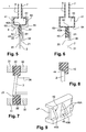
- the support device 1 illustrated on the Figures 1 to 6 is intended to support a substrate 2, such as a silicon wafer, to be treated electro-chemically, in particular electrolytically.
- the substrate 2 is plane.
- the substrate has two main faces 20 and 21 parallel and opposite and a peripheral edge 22 connecting the two faces.
- the edge may be straight or curved with outwardly facing convexity in the opposite direction to the center of the substrate.
- the support device 1 comprises a support 3 which is intended, when the substrate 2 is associated with it, to form a sealed barrier between two electrolytic baths 10 and 11 so as to hermetically isolate the opposite faces 20 and 21 of the substrate, the bath contact with one of the faces of the substrate not to be in contact with the opposite face of the substrate in contact with the other bath.
- the support device comprises sealing means 4 which are associated with the support 3 and are intended to cooperate with the substrate 2.
- the support 3 comprises additional sealing means 5 arranged on at least one external side of said support which is intended to bear against the frame 12.
- a peripheral housing is preferably provided in the outer face 34 of the frame 30 to insert therein the additional sealing means 5.
- the support 3 is pressed against the frame 12 with the additional sealing means 5 in interface, and this by any appropriate pressure means acting on said support 3 according to a force perpendicular to the plane of the substrate 2.
- This arrangement of the additional sealing means 5 is a non-limiting example. They may alternatively be arranged on the outer edge of the support 3 which will be provided to carry one or more substrates.
- the support 3 has a main body in the form of a frame 30, here of circular shape but which could be of different geometry such as rectangular, square, or other.
- the support 3 comprises the sealing means 4 formed of an applied seal 40, and an inflatable deformable element 41 associated with the seal and intended to transmit compressive forces to the seal applied for its clamping against the substrate 2 when it is housed in the frame 30.
- the frame 30 may be one-piece or preferably, as illustrated, formed of two half-frames 31 and 32 fixed to each other removably, which makes it easier to arrange the sealing means 4 in this context and to change them later if necessary.
- the joint plane of the two half-frames is located in a median plane to the frame parallel to the general surfaces of the substrate to be carried.
- the closure / assembly means are adapted to withstand the pressure forces exerted by the inflatable element 41 on the inner walls of the half-frames during clamping of the wafer.
- the frame 30 comprises two opposite and parallel outer faces 33 and 34, an outer edge 35, and an edge or inner wall 36.
- the opening 37 extends in a general plane parallel to the two faces 33 and 34 of the frame, in particular in the median plane joining the two half-frames.
- the substrate 2 is housed in this opening 37 so that its two opposite faces 20 and 21 are parallel or substantially parallel to the general plane of the opening.
- the substrate can be mounted slightly inclined with respect to the plane of the opening 37.
- the seal between the two opposite faces 20 and 21 of the substrate 2 is formed by the seal of application 40 which cooperates with the edge 22 of said substrate.
- the wall seal 40 is associated with the inner wall (inner edge) 36 of the frame 30. It is more particularly accommodated in a housing 6 formed in said wall 36.
- the housing 6 is adapted to the size and shape of the gasket 40 and the inflatable element 41 adapted to cooperate with the gasket 40.
- the housing 6 has a groove or groove which extends over the entire periphery of the internal song 36 of the frame.
- the housing 6 comprises, opposite Figures 4 to 6 , a cavity 60 formed in the thickness of the frame and a radial groove 61.
- the groove 61 extends the cavity 60 narrower and in the general plane of the opening, to open on said opening 37.
- the sealing ring 40 encircles the opening 37. It forms, at least for its portion intended to be in contact with the wafer 22 of the substrate, a closed continuous line.
- the inflatable element 41 is in the form of a closed deformable hose of the hollow seal type provided with an internal chamber 43, and provided with a flexible connector 7 or in the form of an open deformable hose, with elastic properties and preferably resistance to aggression electrolytes similar to those of the seal application.
- the inflatable element 41 has at least one deformable portion under the application of a force by pressurizing or depressurizing the chamber 43.
- the substrate 2 Before pressurization or after depressurization of the inflatable element 41, the substrate 2 is disposed at the level of the opening of the frame 30 such that a clearance exists between the wafer 22 of the substrate and the seal applied to apply against said wafer.
- the wall seal 40 may be solid ( Figures 5 and 6 ), being closed on itself by being hollow (internal cavity closed), or even full and endowed with recesses ( figure 9 ). It has at least one part which is of solid surface to apply continuously against the substrate.
- the wall seal 40 has a closed section to form a peripheral closed line corresponding to the external geometrical shape of the substrate.
- the inflatable element 41 is able to expand, to deform to compress the seal of application 40.
- the inflatable deformable element 41 can exert compressive forces on the seal of application 40, namely a so-called pressurization mode and a depressurization mode.
- the inflatable element 41 In pressurization mode, when no pneumatic pressure is applied to the inflatable element 41, the latter is not expanded, and the gasket 40 closest to the substrate has an inner section (a diameter for one annular shape) larger than the section (the diameter) of the substrate, for effortlessly positioning the substrate in the opening 37 of the frame 30.
- said element 41 When said element 41 is inflated, it compresses the outer edge of the seal 40 to transmit compression to its opposite side so as to press against the slice 22 of the substrate and marry it.
- the wall seal 40 then perfectly encloses the substrate and squeezes its slice 22, as illustrated on the figure 6 .
- the inflatable element 41 In so-called depressurization mode, the inflatable element 41 is initially inflated and expanded, and rests on the seal applied while there is no substrate. To insert the substrate 22 in the opening 37, this is only possible by depressurizing the chamber 43 of the inflatable element 41. In contracting, said element 41 releases the compression that it exerts on the seal of applique 40, which in turn retracts. The wall seal 40 then retracts sufficiently so that its inner perimeter becomes larger than that of the substrate so as to set up the substrate. The return to the atmospheric pressure in the chamber 43 again causes the expansion of the inflatable element 41, which in turn generates the compression of the seal of application 40 and the tightening of the substrate.
- This embodiment of the invention makes it easier to control the homogeneity of the clamping around the entire periphery of the substrate without risk of damaging it, particularly with regard to the size of the compression forces and the distribution of these forces.
- the frame 30 is formed of two half-frames 31 and 32. It is not necessary to open the frame, that is to say to separate the two half-frames, to associate the seal of applies 40 to the frame, the seal can be directly introduced into the groove 61.
- the inner edge of the gasket 40 intended to be in compression against the substrate as well as the compression forces, are adapted to completely cover the profile of the wafer 22 of the substrate ( figure 6 ), or partially as in reference 23 of the figure 7 showing an arrangement of the inclined substrate.
- the stops for positioning the substrate correctly in the plane of the opening could correspond to specific portions of the wall seal.
- the wall seal 40 is profiled comprising a recess 44 forming on the one hand a coplanar volume at the receiving opening of the substrate and on the other hand an abutment against which the substrate 2 rests for its positioning at flat to hold the substrate in the plane of the opening before the clamping operation.
- the inflatable deformable element 41 is of the seal type and comprises an annular inner chamber 43 extending over the entire perimeter of said deformable element.
- a fluid under pressure preferably air
- Pneumatic pressure values applied depend on the hardness of the materials used to manufacture the deformable element. The pressure is for example a few bars.
- depressurization mode the expansion of the inflatable element occurs during its re-atmospheric pressure. The rate of compression exerted by the inflatable element then depends on the hardness of the material used and the amplitude of the prestress initially applied to the inflatable element to introduce it into the cavity 60.
- the device of the invention comprises Figures 1 to 6 ) at least one gas supply connector 7 cooperating with the deformable element 41, and passing through the frame 30 via a pipe 8.
- the connector 7 is connected, from a termination, to the chamber 43 of the seal, and at the level of its opposite end is intended to be connected to a pneumatic system 70.
- the housing 6 of the frame accommodating the inflatable deformable element 41, in particular the cavity 60 housing the inflatable deformable element 41, has a space defined by walls, which is adapted to the increase in volume of the inflatable element and to the main direction of deformation to impose the seal applied 40, that is to say radially towards the opening 37 to exert push forces mainly against said seal applied to the substrate direction.
- the entire perimeter of cavity 60 ( Figures 5 and 6 ) of the frame 30 communicates advantageously with the radial groove 61 at a narrowing 62 formed by the walls 63 and 64 transverse to the faces 33 and 34 of the frame 30 of the support 3 and coplanar or substantially coplanar with the outer edge 40A of the seal 40 applies against which the inflatable deformable element 41 is pressed.
- These transverse walls 63 and 64 constitute abutments for the expansion of the inflatable deformable element, thus making it possible to effectively fix a limit of maximum stress applicable on the wall seal.
- these stops 63 and 64 ensure that the seal of application 40, and therefore the substrate, undergo a constant stress.
- the inflatable element 41 does not compress the seal of application 40, said seal does not come to grip the substrate 2.
- the substrate 2 is then temporarily maintained at the level of the opening 37 thanks to the wedging means 38 ( Figures 1 to 4 ) provided on the inner periphery of the frame or else resting on the recess 44 of the seal of application 40 by a suitable profile ( figure 8 ).
- the inflatable element 41 does not compress the wall seal 40, the hermeticity between the two baths 10 and 11 is not ensured, neither between the substrate 2 and the wall seal 40, nor between the and the inflatable member 41 and ni between the inflatable member 41 and the frame 30.
- the hermeticity between the two baths is ensured at all levels between the frame 30 and the inflatable element 41, the inflatable element 41 and the seal of application 40 and the applied joint 40 and the substrate 2.
- the figure 9 illustrates a partial view of a variant of the gasket 40 having in its thickness blind recesses (not through) 45 (the recesses being hollowed in the direction perpendicular to its longitudinal extension).
- the seal remains solid at the level of its opposite outer edges intended to be in contact with the substrate and the inflatable element 41.
- the shape, the depth and the judicious location of these recesses are intended to promote the displacement of the seal of applied in direction of the substrate.
- the reduction in the volume of deformable material of the seal makes it possible to reduce the amount of energy to be stored in order to reach a given displacement amplitude. At constant energy, the seal provided with these recesses will increase its travel towards the substrate.
- the solid portions 45A between two recesses 45 preferably have a triangular shape, one vertex of the triangle is placed on the side of the portion intended to be applied against the substrate while the base opposite of the triangle is substantially parallel to the outer edge of the seal, so as to channel and conduct the forces in the material between the recesses and deform the seal with an increased amplitude of movement radially against the substrate, concentrating the compression forces towards the tip of the triangles.
- the bottom 45B of the recesses 45 forms a tight membrane ensuring the hermeticity between the baths 10 and 11 during clamping of the substrate.
- the figure 10a illustrates a device 1 of the invention having several openings 37, here two, each of them being provided with a separate inflatable deformable element 41, for housing and treating several substrates concomitantly.
- Each opening 37 is delimited by a frame having a groove hosting a seal of apply 40.
- Setting means 38 are provided to maintain in position before clamping the substrate to be treated.
- the figure 10b shows an exploded view of the figure 8 .
- the support 3 formed of two assembled half-frames 31 and 32 delimiting two frames 30 for two openings 37, and a seal of application 40 and an inflatable element 41 by opening.
- the device of the invention has the advantage of easily adapting to all types of shapes and dimensions of a substrate by associating on the one hand with each opening 37, an additional frame 39 said guiding associated with the support 3, and secondly a wider application seal 40 adapted to the shape of the guide frame and the shape of the substrate.
- the function of the guide frame 39 is to reduce the size / shape of the opening 37 in order to adapt it to the size / shape of the substrate 2 without having to modify either the support 3 or the inflatable element 41.
- Another function of the frame 39 is to guide the radial movement of the gasket 40 without lateral deformation of said gasket.
- the guiding frame 39 is for example formed of two half-frames 39A and 39B removably associated by fixing means 3A to the support 3 on either side of each opening 37.
- the adaptation frame 39 is attached against the initial frame 30 of the support 3 which comprises the inflatable element 41.
- the adaptation frame 39 has on the one hand an external shape 39C adapted to cooperate with the support 3, and on the other hand, an internal form 39D of shape adapted to the geometry of the substrate to be accommodated. On the Figures 9 to 11 this internal form 39D is circular.
- the half-frame 39A opposite that bearing the wedging elements 38, is beveled so as to facilitate the flow of the electrolyte and the evacuation of gaseous emissions that may occur on the surface of the substrate.
- the adapter frame 39 has an outer circular shape 39C to cooperate with the frame 30 and a rectangular inner shape 39D to cooperate with a corresponding rectangular shape of the substrate.
- the adaptation frame 39 composed of the two half-frames 39A and 39B, forms a receiving housing 39E for the seal of application 40.
- the receiving housing 39E is located in the extension of the groove 61 of the support 3; its walls serve to maintain and guide the applying seal 40 so that, upon expansion of the inflatable member 41, the compressive forces transmitted by the seam seal 40 are directed toward the opening 37.
- the seal of application 40 has a shape and dimensions adapted to, firstly be housed in the groove 61 of the support 3 and in the housing 39E of the frame 39, and secondly cooperate with the profile of the periphery of the substrate .
- the gasket 40 comprises a lug 40A for cooperating with a female shape of the "notch" type of a silicon wafer.
- the device 1 may comprise in its internal structure a deformable element 41 associated with each gasket 40, as illustrated in FIG. figure 10a .
- the device comprises a single deformable element 41 of flexible hose type which has a length adapted to surround each seal of application 40.
- the inflatable element 41 is no longer an inflatable seal with closed section, but follows a continuous line since a first pipe 8A, snaking around each gasket, until it comes out of the outlet 3 of the support via a second pipe 8B.
- each gasket 40 has a locally adapted profile, here in the form of spout 46, for sealing the space formed at the inlet and outlet junction of the pipe at a point of each opening of the frame for housing a substrate 2.
- the inflatable element 41 is tightened to encircle each opening without being able to join at right angles. Expansion of the inflatable member 41 (regardless of the pressurization / depressurization mode) causes compression of the seals and the nip of each of the nozzles 46, thereby sealing.
- the sum of the compressive forces exerted on a spout 46 contributes to deforming the applied seal towards the substrate 2, thus ensuring a perfect seal between the support 3 and the inflatable element 41, as well as between the element inflatable 41 and the seals 40 and between the seals 40 and the substrates 2.
- the support device of the invention for a substrate to be processed makes it possible, by the general shape in the frame of the support body, the presence of sealing means on the inner periphery of the frame, the adaptation sealing means to expand, in particular under the effect of a pneumatic pressure or pressure release, to mount / dismount the substrate to this support in a rapid manner, repeated for industrial application, and to provide an effective seal between the two opposite surfaces of the substrate while maximizing the surface to be treated of the substrate.
- the wall seal is thus deformable in turn, which allows a controlled cooperation with the substrate according to the edge of the latter, so as to limit the area of overlap of the gasket to the edge of the substrate, thus maximizing the area suitable for treatment.
- the device of the invention in particular the support, is usable for several forms of substrates, only is to manufacture a specific application seal to each geometry of the substrate and possibly a guide frame when the seal applies becomes too wide.
- This support device accepts sets of guide frames and additional wall seals intended to adapt the support to any type of substrate shape and size to be treated.
- the device of the invention can process several substrates at a time.
Landscapes
- Chemical & Material Sciences (AREA)
- Engineering & Computer Science (AREA)
- Chemical Kinetics & Catalysis (AREA)
- Electrochemistry (AREA)
- Materials Engineering (AREA)
- Metallurgy (AREA)
- Organic Chemistry (AREA)
- Life Sciences & Earth Sciences (AREA)
- Sustainable Development (AREA)
- Container, Conveyance, Adherence, Positioning, Of Wafer (AREA)
Applications Claiming Priority (1)
| Application Number | Priority Date | Filing Date | Title |
|---|---|---|---|
| FR1557373A FR3039563B1 (fr) | 2015-07-31 | 2015-07-31 | Dispositif de support adaptable pour substrats a traiter notamment par voie chimique ou electrochimique |
Publications (2)
| Publication Number | Publication Date |
|---|---|
| EP3124655A1 true EP3124655A1 (de) | 2017-02-01 |
| EP3124655B1 EP3124655B1 (de) | 2018-09-12 |
Family
ID=54291478
Family Applications (1)
| Application Number | Title | Priority Date | Filing Date |
|---|---|---|---|
| EP16180805.0A Active EP3124655B1 (de) | 2015-07-31 | 2016-07-22 | Anpassbare haltevorrichtung für substrate, die insbesondere chemisch oder elektrochemisch behandelt werden sollen |
Country Status (2)
| Country | Link |
|---|---|
| EP (1) | EP3124655B1 (de) |
| FR (1) | FR3039563B1 (de) |
Cited By (1)
| Publication number | Priority date | Publication date | Assignee | Title |
|---|---|---|---|---|
| CN119666994A (zh) * | 2025-02-20 | 2025-03-21 | 津上智造智能科技江苏有限公司 | 水浸式超声扫描显微镜晶圆检测用承载装置 |
Families Citing this family (1)
| Publication number | Priority date | Publication date | Assignee | Title |
|---|---|---|---|---|
| US20240376629A1 (en) * | 2021-09-27 | 2024-11-14 | Socpra Sciences Et Genie S.E.C. | Wafer receiver, electrochemical porosification apparatus and method using same |
Citations (3)
| Publication number | Priority date | Publication date | Assignee | Title |
|---|---|---|---|---|
| FR2315028A1 (fr) * | 1975-06-17 | 1977-01-14 | Quadrimetal Offset | Organes de prehension gonflables |
| EP0597428A1 (de) | 1992-11-09 | 1994-05-18 | Canon Kabushiki Kaisha | Anodisierungsapparat mit einer Trägervorrichtung für das zu behandelnde Substrat |
| US20060103830A1 (en) * | 2004-11-18 | 2006-05-18 | International Business Machines Corporation | Method and apparatus for immersion lithography |
-
2015
- 2015-07-31 FR FR1557373A patent/FR3039563B1/fr not_active Expired - Fee Related
-
2016
- 2016-07-22 EP EP16180805.0A patent/EP3124655B1/de active Active
Patent Citations (3)
| Publication number | Priority date | Publication date | Assignee | Title |
|---|---|---|---|---|
| FR2315028A1 (fr) * | 1975-06-17 | 1977-01-14 | Quadrimetal Offset | Organes de prehension gonflables |
| EP0597428A1 (de) | 1992-11-09 | 1994-05-18 | Canon Kabushiki Kaisha | Anodisierungsapparat mit einer Trägervorrichtung für das zu behandelnde Substrat |
| US20060103830A1 (en) * | 2004-11-18 | 2006-05-18 | International Business Machines Corporation | Method and apparatus for immersion lithography |
Cited By (2)
| Publication number | Priority date | Publication date | Assignee | Title |
|---|---|---|---|---|
| CN119666994A (zh) * | 2025-02-20 | 2025-03-21 | 津上智造智能科技江苏有限公司 | 水浸式超声扫描显微镜晶圆检测用承载装置 |
| CN119666994B (zh) * | 2025-02-20 | 2025-06-03 | 津上智造智能科技江苏有限公司 | 水浸式超声扫描显微镜晶圆检测用承载装置 |
Also Published As
| Publication number | Publication date |
|---|---|
| FR3039563B1 (fr) | 2017-08-25 |
| FR3039563A1 (fr) | 2017-02-03 |
| EP3124655B1 (de) | 2018-09-12 |
Similar Documents
| Publication | Publication Date | Title |
|---|---|---|
| EP1694178B1 (de) | Lippendichtung für ein kochgerät und mit der dichtung versehenes kochgerät | |
| WO1989005209A1 (fr) | Procede de soudage au moyen d'un faisceau laser, notamment applicable au soudage de pieces en verre | |
| EP3124655B1 (de) | Anpassbare haltevorrichtung für substrate, die insbesondere chemisch oder elektrochemisch behandelt werden sollen | |
| FR2570160A1 (fr) | Dispositif de raccordement de canalisations, empechant une separation desdites canalisations | |
| FR2576535A1 (fr) | Element de serrage | |
| EP2071216A1 (de) | Superplastische Dichtungsfuge, insbesondere für System mit elektrochemischen Zellen | |
| EP0821996A1 (de) | Flüssigkeitsbehandlungsmodul mit steifer Membran und Gebrauchsverfahren desselben | |
| FR3039564A1 (fr) | Dispositif de support pour substrat a traiter notamment par voie chimique ou electrochimique | |
| EP2236864B1 (de) | Metalllippendichtung und mit einer solchen Dichtung ausgestattete Maschine | |
| EP2084435B1 (de) | Doppeldichtung für eine maschine zur plasmabehandlung von behältern | |
| FR2999460A1 (fr) | Procede d'assemblage par sertissage magnetique | |
| EP0238431A1 (de) | Verbindungsvorrichtung zwischen Rohren mit einem Einschiessbaren und einem aufnehmenden Teil | |
| EP0030905A2 (de) | Vorrichtung zur abdichtenden Befestigung halbdurchlässiger Membranen auf Halteplatten von Trennapparaten | |
| WO2003078144A1 (fr) | Procede pour l'obtention d'une lentille optique ainsi que joint et dispositif pour sa mise en oeuvre | |
| EP3541545B1 (de) | Verfahren zur elektrohydraulischen formung und zugehörige vorrichtung | |
| EP3240650B1 (de) | Elektrohydraulische formvorrichtung | |
| FR2670051A1 (fr) | Procede et dispositif de fabrication d'un support d'electrolyte solide et support d'electrolyte solide obtenu par ce procede. | |
| FR2673383A1 (fr) | Dispositif de filtration des elements solides contenus dans un liquide. | |
| WO2020165538A1 (fr) | Procédé de formage hybride et dispositif de formage correspondant | |
| EP3068485A1 (de) | Durchführungsvorrichtung, insbesondere für ein medizinisches implantatsystem und herstellungsverfahren | |
| EP3181732B1 (de) | Zelle für eine chemische reaktion mit geringen volumen | |
| EP0267095B1 (de) | Dichtende Drehkupplung for Hochdruckmedium | |
| FR2759106A1 (fr) | Procede de realisation simultanee de deux parois en beton separees par un espace vide | |
| FR2678997A1 (fr) | Joint d'etancheite a ame metallique et garnitures en graphite expanse. | |
| WO1997028395A1 (fr) | Procede de raccordement etanche |
Legal Events
| Date | Code | Title | Description |
|---|---|---|---|
| PUAI | Public reference made under article 153(3) epc to a published international application that has entered the european phase |
Free format text: ORIGINAL CODE: 0009012 |
|
| STAA | Information on the status of an ep patent application or granted ep patent |
Free format text: STATUS: THE APPLICATION HAS BEEN PUBLISHED |
|
| AK | Designated contracting states |
Kind code of ref document: A1 Designated state(s): AL AT BE BG CH CY CZ DE DK EE ES FI FR GB GR HR HU IE IS IT LI LT LU LV MC MK MT NL NO PL PT RO RS SE SI SK SM TR |
|
| AX | Request for extension of the european patent |
Extension state: BA ME |
|
| STAA | Information on the status of an ep patent application or granted ep patent |
Free format text: STATUS: REQUEST FOR EXAMINATION WAS MADE |
|
| 17P | Request for examination filed |
Effective date: 20170725 |
|
| RBV | Designated contracting states (corrected) |
Designated state(s): AL AT BE BG CH CY CZ DE DK EE ES FI FR GB GR HR HU IE IS IT LI LT LU LV MC MK MT NL NO PL PT RO RS SE SI SK SM TR |
|
| GRAP | Despatch of communication of intention to grant a patent |
Free format text: ORIGINAL CODE: EPIDOSNIGR1 |
|
| STAA | Information on the status of an ep patent application or granted ep patent |
Free format text: STATUS: GRANT OF PATENT IS INTENDED |
|
| INTG | Intention to grant announced |
Effective date: 20171215 |
|
| GRAS | Grant fee paid |
Free format text: ORIGINAL CODE: EPIDOSNIGR3 |
|
| GRAA | (expected) grant |
Free format text: ORIGINAL CODE: 0009210 |
|
| STAA | Information on the status of an ep patent application or granted ep patent |
Free format text: STATUS: THE PATENT HAS BEEN GRANTED |
|
| AK | Designated contracting states |
Kind code of ref document: B1 Designated state(s): AL AT BE BG CH CY CZ DE DK EE ES FI FR GB GR HR HU IE IS IT LI LT LU LV MC MK MT NL NO PL PT RO RS SE SI SK SM TR |
|
| REG | Reference to a national code |
Ref country code: GB Ref legal event code: FG4D Free format text: NOT ENGLISH |
|
| REG | Reference to a national code |
Ref country code: CH Ref legal event code: EP |
|
| REG | Reference to a national code |
Ref country code: IE Ref legal event code: FG4D Free format text: LANGUAGE OF EP DOCUMENT: FRENCH |
|
| REG | Reference to a national code |
Ref country code: DE Ref legal event code: R096 Ref document number: 602016003084 Country of ref document: DE |
|
| REG | Reference to a national code |
Ref country code: AT Ref legal event code: REF Ref document number: 999651 Country of ref document: AT Kind code of ref document: T Effective date: 20180615 |
|
| REG | Reference to a national code |
Ref country code: FR Ref legal event code: PLFP Year of fee payment: 3 |
|
| PUAC | Information related to the publication of a b1 document modified or deleted |
Free format text: ORIGINAL CODE: 0009299EPPU |
|
| STAA | Information on the status of an ep patent application or granted ep patent |
Free format text: STATUS: GRANT OF PATENT IS INTENDED |
|
| REG | Reference to a national code |
Ref country code: CH Ref legal event code: PK Free format text: LA DELIVRANCE DU BREVET A ETE REVOQUEE PAR L'OEB. |
|
| GRAA | (expected) grant |
Free format text: ORIGINAL CODE: 0009210 |
|
| STAA | Information on the status of an ep patent application or granted ep patent |
Free format text: STATUS: THE PATENT HAS BEEN GRANTED |
|
| DB1 | Publication of patent cancelled |
Effective date: 20180720 |
|
| RAP1 | Party data changed (applicant data changed or rights of an application transferred) |
Owner name: SILIMIXT |
|
| AK | Designated contracting states |
Kind code of ref document: B1 Designated state(s): AL AT BE BG CH CY CZ DE DK EE ES FI FR GB GR HR HU IE IS IT LI LT LU LV MC MK MT NL NO PL PT RO RS SE SI SK SM TR |
|
| REG | Reference to a national code |
Ref country code: LU Ref legal event code: HK Effective date: 20180815 |
|
| REG | Reference to a national code |
Ref country code: DE Ref legal event code: R107 Ref document number: 602016003084 Country of ref document: DE |
|
| REG | Reference to a national code |
Ref country code: DE Ref legal event code: R096 Ref document number: 602016003084 Country of ref document: DE |
|
| REG | Reference to a national code |
Ref country code: AT Ref legal event code: REF Ref document number: 999651 Country of ref document: AT Kind code of ref document: T Effective date: 20181015 |
|
| REG | Reference to a national code |
Ref country code: CH Ref legal event code: EP Ref country code: CH Ref legal event code: PK Free format text: LA DELIVRANCE DU 16.05.2018 A ETE REVOQUEE PAR L'OEB |
|
| REG | Reference to a national code |
Ref country code: NL Ref legal event code: MP Effective date: 20180912 |
|
| REG | Reference to a national code |
Ref country code: LT Ref legal event code: MG4D |
|
| PG25 | Lapsed in a contracting state [announced via postgrant information from national office to epo] |
Ref country code: BG Free format text: LAPSE BECAUSE OF FAILURE TO SUBMIT A TRANSLATION OF THE DESCRIPTION OR TO PAY THE FEE WITHIN THE PRESCRIBED TIME-LIMIT Effective date: 20181212 Ref country code: RS Free format text: LAPSE BECAUSE OF FAILURE TO SUBMIT A TRANSLATION OF THE DESCRIPTION OR TO PAY THE FEE WITHIN THE PRESCRIBED TIME-LIMIT Effective date: 20180912 Ref country code: LT Free format text: LAPSE BECAUSE OF FAILURE TO SUBMIT A TRANSLATION OF THE DESCRIPTION OR TO PAY THE FEE WITHIN THE PRESCRIBED TIME-LIMIT Effective date: 20180912 Ref country code: NO Free format text: LAPSE BECAUSE OF FAILURE TO SUBMIT A TRANSLATION OF THE DESCRIPTION OR TO PAY THE FEE WITHIN THE PRESCRIBED TIME-LIMIT Effective date: 20181212 Ref country code: FI Free format text: LAPSE BECAUSE OF FAILURE TO SUBMIT A TRANSLATION OF THE DESCRIPTION OR TO PAY THE FEE WITHIN THE PRESCRIBED TIME-LIMIT Effective date: 20180912 |
|
| PG25 | Lapsed in a contracting state [announced via postgrant information from national office to epo] |
Ref country code: AL Free format text: LAPSE BECAUSE OF FAILURE TO SUBMIT A TRANSLATION OF THE DESCRIPTION OR TO PAY THE FEE WITHIN THE PRESCRIBED TIME-LIMIT Effective date: 20180912 Ref country code: HR Free format text: LAPSE BECAUSE OF FAILURE TO SUBMIT A TRANSLATION OF THE DESCRIPTION OR TO PAY THE FEE WITHIN THE PRESCRIBED TIME-LIMIT Effective date: 20180912 |
|
| PG25 | Lapsed in a contracting state [announced via postgrant information from national office to epo] |
Ref country code: NL Free format text: LAPSE BECAUSE OF FAILURE TO SUBMIT A TRANSLATION OF THE DESCRIPTION OR TO PAY THE FEE WITHIN THE PRESCRIBED TIME-LIMIT Effective date: 20180912 Ref country code: EE Free format text: LAPSE BECAUSE OF FAILURE TO SUBMIT A TRANSLATION OF THE DESCRIPTION OR TO PAY THE FEE WITHIN THE PRESCRIBED TIME-LIMIT Effective date: 20180912 Ref country code: IT Free format text: LAPSE BECAUSE OF FAILURE TO SUBMIT A TRANSLATION OF THE DESCRIPTION OR TO PAY THE FEE WITHIN THE PRESCRIBED TIME-LIMIT Effective date: 20180912 Ref country code: RO Free format text: LAPSE BECAUSE OF FAILURE TO SUBMIT A TRANSLATION OF THE DESCRIPTION OR TO PAY THE FEE WITHIN THE PRESCRIBED TIME-LIMIT Effective date: 20180912 Ref country code: ES Free format text: LAPSE BECAUSE OF FAILURE TO SUBMIT A TRANSLATION OF THE DESCRIPTION OR TO PAY THE FEE WITHIN THE PRESCRIBED TIME-LIMIT Effective date: 20180912 Ref country code: CZ Free format text: LAPSE BECAUSE OF FAILURE TO SUBMIT A TRANSLATION OF THE DESCRIPTION OR TO PAY THE FEE WITHIN THE PRESCRIBED TIME-LIMIT Effective date: 20180912 |
|
| PG25 | Lapsed in a contracting state [announced via postgrant information from national office to epo] |
Ref country code: SM Free format text: LAPSE BECAUSE OF FAILURE TO SUBMIT A TRANSLATION OF THE DESCRIPTION OR TO PAY THE FEE WITHIN THE PRESCRIBED TIME-LIMIT Effective date: 20180912 Ref country code: SK Free format text: LAPSE BECAUSE OF FAILURE TO SUBMIT A TRANSLATION OF THE DESCRIPTION OR TO PAY THE FEE WITHIN THE PRESCRIBED TIME-LIMIT Effective date: 20180912 |
|
| REG | Reference to a national code |
Ref country code: DE Ref legal event code: R097 Ref document number: 602016003084 Country of ref document: DE |
|
| PLBE | No opposition filed within time limit |
Free format text: ORIGINAL CODE: 0009261 |
|
| STAA | Information on the status of an ep patent application or granted ep patent |
Free format text: STATUS: NO OPPOSITION FILED WITHIN TIME LIMIT |
|
| PG25 | Lapsed in a contracting state [announced via postgrant information from national office to epo] |
Ref country code: DK Free format text: LAPSE BECAUSE OF FAILURE TO SUBMIT A TRANSLATION OF THE DESCRIPTION OR TO PAY THE FEE WITHIN THE PRESCRIBED TIME-LIMIT Effective date: 20180912 Ref country code: MC Free format text: LAPSE BECAUSE OF FAILURE TO SUBMIT A TRANSLATION OF THE DESCRIPTION OR TO PAY THE FEE WITHIN THE PRESCRIBED TIME-LIMIT Effective date: 20180912 |
|
| 26N | No opposition filed |
Effective date: 20190613 |
|
| PG25 | Lapsed in a contracting state [announced via postgrant information from national office to epo] |
Ref country code: SI Free format text: LAPSE BECAUSE OF FAILURE TO SUBMIT A TRANSLATION OF THE DESCRIPTION OR TO PAY THE FEE WITHIN THE PRESCRIBED TIME-LIMIT Effective date: 20180912 |
|
| REG | Reference to a national code |
Ref country code: AT Ref legal event code: MK05 Ref document number: 999651 Country of ref document: AT Kind code of ref document: T Effective date: 20180912 |
|
| PG25 | Lapsed in a contracting state [announced via postgrant information from national office to epo] |
Ref country code: AT Free format text: LAPSE BECAUSE OF FAILURE TO SUBMIT A TRANSLATION OF THE DESCRIPTION OR TO PAY THE FEE WITHIN THE PRESCRIBED TIME-LIMIT Effective date: 20180912 |
|
| REG | Reference to a national code |
Ref country code: DE Ref legal event code: R119 Ref document number: 602016003084 Country of ref document: DE |
|
| REG | Reference to a national code |
Ref country code: CH Ref legal event code: PL |
|
| PG25 | Lapsed in a contracting state [announced via postgrant information from national office to epo] |
Ref country code: TR Free format text: LAPSE BECAUSE OF FAILURE TO SUBMIT A TRANSLATION OF THE DESCRIPTION OR TO PAY THE FEE WITHIN THE PRESCRIBED TIME-LIMIT Effective date: 20180912 |
|
| REG | Reference to a national code |
Ref country code: BE Ref legal event code: MM Effective date: 20190731 |
|
| PG25 | Lapsed in a contracting state [announced via postgrant information from national office to epo] |
Ref country code: DE Free format text: LAPSE BECAUSE OF NON-PAYMENT OF DUE FEES Effective date: 20200201 |
|
| PG25 | Lapsed in a contracting state [announced via postgrant information from national office to epo] |
Ref country code: BE Free format text: LAPSE BECAUSE OF NON-PAYMENT OF DUE FEES Effective date: 20190731 Ref country code: LU Free format text: LAPSE BECAUSE OF NON-PAYMENT OF DUE FEES Effective date: 20190722 Ref country code: LI Free format text: LAPSE BECAUSE OF NON-PAYMENT OF DUE FEES Effective date: 20190731 Ref country code: CH Free format text: LAPSE BECAUSE OF NON-PAYMENT OF DUE FEES Effective date: 20190731 |
|
| PG25 | Lapsed in a contracting state [announced via postgrant information from national office to epo] |
Ref country code: IE Free format text: LAPSE BECAUSE OF NON-PAYMENT OF DUE FEES Effective date: 20190722 |
|
| GBPC | Gb: european patent ceased through non-payment of renewal fee |
Effective date: 20200722 |
|
| PG25 | Lapsed in a contracting state [announced via postgrant information from national office to epo] |
Ref country code: LV Free format text: LAPSE BECAUSE OF NON-PAYMENT OF DUE FEES Effective date: 20180912 Ref country code: GB Free format text: LAPSE BECAUSE OF NON-PAYMENT OF DUE FEES Effective date: 20200722 |
|
| PG25 | Lapsed in a contracting state [announced via postgrant information from national office to epo] |
Ref country code: CY Free format text: LAPSE BECAUSE OF FAILURE TO SUBMIT A TRANSLATION OF THE DESCRIPTION OR TO PAY THE FEE WITHIN THE PRESCRIBED TIME-LIMIT Effective date: 20180912 |
|
| PG25 | Lapsed in a contracting state [announced via postgrant information from national office to epo] |
Ref country code: GR Free format text: LAPSE BECAUSE OF FAILURE TO SUBMIT A TRANSLATION OF THE DESCRIPTION OR TO PAY THE FEE WITHIN THE PRESCRIBED TIME-LIMIT Effective date: 20180912 Ref country code: SE Free format text: LAPSE BECAUSE OF NON-PAYMENT OF DUE FEES Effective date: 20180926 Ref country code: IS Free format text: LAPSE BECAUSE OF FAILURE TO SUBMIT A TRANSLATION OF THE DESCRIPTION OR TO PAY THE FEE WITHIN THE PRESCRIBED TIME-LIMIT Effective date: 20190112 |
|
| PG25 | Lapsed in a contracting state [announced via postgrant information from national office to epo] |
Ref country code: MT Free format text: LAPSE BECAUSE OF FAILURE TO SUBMIT A TRANSLATION OF THE DESCRIPTION OR TO PAY THE FEE WITHIN THE PRESCRIBED TIME-LIMIT Effective date: 20180912 Ref country code: HU Free format text: LAPSE BECAUSE OF FAILURE TO SUBMIT A TRANSLATION OF THE DESCRIPTION OR TO PAY THE FEE WITHIN THE PRESCRIBED TIME-LIMIT; INVALID AB INITIO Effective date: 20160722 |
|
| PG25 | Lapsed in a contracting state [announced via postgrant information from national office to epo] |
Ref country code: MK Free format text: LAPSE BECAUSE OF FAILURE TO SUBMIT A TRANSLATION OF THE DESCRIPTION OR TO PAY THE FEE WITHIN THE PRESCRIBED TIME-LIMIT Effective date: 20180912 |
|
| PG25 | Lapsed in a contracting state [announced via postgrant information from national office to epo] |
Ref country code: PT Free format text: LAPSE BECAUSE OF FAILURE TO SUBMIT A TRANSLATION OF THE DESCRIPTION OR TO PAY THE FEE WITHIN THE PRESCRIBED TIME-LIMIT Effective date: 20180912 |
|
| PG25 | Lapsed in a contracting state [announced via postgrant information from national office to epo] |
Ref country code: PL Free format text: LAPSE BECAUSE OF FAILURE TO SUBMIT A TRANSLATION OF THE DESCRIPTION OR TO PAY THE FEE WITHIN THE PRESCRIBED TIME-LIMIT Effective date: 20180912 |
|
| PGFP | Annual fee paid to national office [announced via postgrant information from national office to epo] |
Ref country code: FR Payment date: 20251128 Year of fee payment: 10 |