EP3124731A1 - Fenêtres - Google Patents
Fenêtres Download PDFInfo
- Publication number
- EP3124731A1 EP3124731A1 EP16275108.5A EP16275108A EP3124731A1 EP 3124731 A1 EP3124731 A1 EP 3124731A1 EP 16275108 A EP16275108 A EP 16275108A EP 3124731 A1 EP3124731 A1 EP 3124731A1
- Authority
- EP
- European Patent Office
- Prior art keywords
- frame
- sash
- window
- lock
- frame element
- Prior art date
- Legal status (The legal status is an assumption and is not a legal conclusion. Google has not performed a legal analysis and makes no representation as to the accuracy of the status listed.)
- Withdrawn
Links
- 239000000463 material Substances 0.000 claims description 13
- 229920002430 Fibre-reinforced plastic Polymers 0.000 claims description 12
- 239000011151 fibre-reinforced plastic Substances 0.000 claims description 12
- 229920003023 plastic Polymers 0.000 claims description 6
- 239000004033 plastic Substances 0.000 claims description 6
- 239000002023 wood Substances 0.000 claims description 5
- 229920001187 thermosetting polymer Polymers 0.000 claims description 4
- 230000009286 beneficial effect Effects 0.000 description 7
- 239000000853 adhesive Substances 0.000 description 6
- 230000001070 adhesive effect Effects 0.000 description 6
- 230000007613 environmental effect Effects 0.000 description 4
- 239000004411 aluminium Substances 0.000 description 3
- 229910052782 aluminium Inorganic materials 0.000 description 3
- XAGFODPZIPBFFR-UHFFFAOYSA-N aluminium Chemical compound [Al] XAGFODPZIPBFFR-UHFFFAOYSA-N 0.000 description 3
- 230000008901 benefit Effects 0.000 description 3
- 238000012856 packing Methods 0.000 description 3
- XEEYBQQBJWHFJM-UHFFFAOYSA-N Iron Chemical compound [Fe] XEEYBQQBJWHFJM-UHFFFAOYSA-N 0.000 description 2
- 238000010276 construction Methods 0.000 description 2
- 229910052751 metal Inorganic materials 0.000 description 2
- 239000002184 metal Substances 0.000 description 2
- 230000000717 retained effect Effects 0.000 description 2
- 239000007787 solid Substances 0.000 description 2
- 229910000831 Steel Inorganic materials 0.000 description 1
- 230000004075 alteration Effects 0.000 description 1
- 238000004140 cleaning Methods 0.000 description 1
- 150000001875 compounds Chemical class 0.000 description 1
- 230000000694 effects Effects 0.000 description 1
- 210000003195 fascia Anatomy 0.000 description 1
- -1 for example Polymers 0.000 description 1
- 239000011521 glass Substances 0.000 description 1
- 239000011121 hardwood Substances 0.000 description 1
- 229910052742 iron Inorganic materials 0.000 description 1
- 230000002093 peripheral effect Effects 0.000 description 1
- 230000000704 physical effect Effects 0.000 description 1
- 229920000642 polymer Polymers 0.000 description 1
- 230000001681 protective effect Effects 0.000 description 1
- 230000002787 reinforcement Effects 0.000 description 1
- 239000011347 resin Substances 0.000 description 1
- 229920005989 resin Polymers 0.000 description 1
- 230000002441 reversible effect Effects 0.000 description 1
- 238000004513 sizing Methods 0.000 description 1
- 239000011122 softwood Substances 0.000 description 1
- 239000010959 steel Substances 0.000 description 1
- 230000000007 visual effect Effects 0.000 description 1
Images



Classifications
-
- E—FIXED CONSTRUCTIONS
- E06—DOORS, WINDOWS, SHUTTERS, OR ROLLER BLINDS IN GENERAL; LADDERS
- E06B—FIXED OR MOVABLE CLOSURES FOR OPENINGS IN BUILDINGS, VEHICLES, FENCES OR LIKE ENCLOSURES IN GENERAL, e.g. DOORS, WINDOWS, BLINDS, GATES
- E06B1/00—Border constructions of openings in walls, floors, or ceilings; Frames to be rigidly mounted in such openings
- E06B1/04—Frames for doors, windows, or the like to be fixed in openings
- E06B1/32—Frames composed of parts made of different materials
-
- E—FIXED CONSTRUCTIONS
- E06—DOORS, WINDOWS, SHUTTERS, OR ROLLER BLINDS IN GENERAL; LADDERS
- E06B—FIXED OR MOVABLE CLOSURES FOR OPENINGS IN BUILDINGS, VEHICLES, FENCES OR LIKE ENCLOSURES IN GENERAL, e.g. DOORS, WINDOWS, BLINDS, GATES
- E06B3/00—Window sashes, door leaves, or like elements for closing wall or like openings; Layout of fixed or moving closures, e.g. windows in wall or like openings; Features of rigidly-mounted outer frames relating to the mounting of wing frames
- E06B3/32—Arrangements of wings characterised by the manner of movement; Arrangements of movable wings in openings; Features of wings or frames relating solely to the manner of movement of the wing
- E06B3/34—Arrangements of wings characterised by the manner of movement; Arrangements of movable wings in openings; Features of wings or frames relating solely to the manner of movement of the wing with only one kind of movement
- E06B3/38—Arrangements of wings characterised by the manner of movement; Arrangements of movable wings in openings; Features of wings or frames relating solely to the manner of movement of the wing with only one kind of movement with a horizontal axis of rotation at the top or bottom of the opening
-
- E—FIXED CONSTRUCTIONS
- E06—DOORS, WINDOWS, SHUTTERS, OR ROLLER BLINDS IN GENERAL; LADDERS
- E06B—FIXED OR MOVABLE CLOSURES FOR OPENINGS IN BUILDINGS, VEHICLES, FENCES OR LIKE ENCLOSURES IN GENERAL, e.g. DOORS, WINDOWS, BLINDS, GATES
- E06B3/00—Window sashes, door leaves, or like elements for closing wall or like openings; Layout of fixed or moving closures, e.g. windows in wall or like openings; Features of rigidly-mounted outer frames relating to the mounting of wing frames
- E06B3/04—Wing frames not characterised by the manner of movement
- E06B3/26—Compound frames, i.e. one frame within or behind another
-
- E—FIXED CONSTRUCTIONS
- E06—DOORS, WINDOWS, SHUTTERS, OR ROLLER BLINDS IN GENERAL; LADDERS
- E06B—FIXED OR MOVABLE CLOSURES FOR OPENINGS IN BUILDINGS, VEHICLES, FENCES OR LIKE ENCLOSURES IN GENERAL, e.g. DOORS, WINDOWS, BLINDS, GATES
- E06B3/00—Window sashes, door leaves, or like elements for closing wall or like openings; Layout of fixed or moving closures, e.g. windows in wall or like openings; Features of rigidly-mounted outer frames relating to the mounting of wing frames
- E06B3/54—Fixing of glass panes or like plates
- E06B3/58—Fixing of glass panes or like plates by means of borders, cleats, or the like
- E06B3/5807—Fixing of glass panes or like plates by means of borders, cleats, or the like not adjustable
- E06B3/5821—Fixing of glass panes or like plates by means of borders, cleats, or the like not adjustable hooked on or in the frame member, fixed by clips or otherwise elastically fixed
-
- E—FIXED CONSTRUCTIONS
- E06—DOORS, WINDOWS, SHUTTERS, OR ROLLER BLINDS IN GENERAL; LADDERS
- E06B—FIXED OR MOVABLE CLOSURES FOR OPENINGS IN BUILDINGS, VEHICLES, FENCES OR LIKE ENCLOSURES IN GENERAL, e.g. DOORS, WINDOWS, BLINDS, GATES
- E06B7/00—Special arrangements or measures in connection with doors or windows
- E06B7/16—Sealing arrangements on wings or parts co-operating with the wings
- E06B7/22—Sealing arrangements on wings or parts co-operating with the wings by means of elastic edgings, e.g. elastic rubber tubes; by means of resilient edgings, e.g. felt or plush strips, resilient metal strips
- E06B7/23—Plastic, sponge rubber, or like strips or tubes
- E06B7/2305—Plastic, sponge rubber, or like strips or tubes with an integrally formed part for fixing the edging
- E06B7/2307—Plastic, sponge rubber, or like strips or tubes with an integrally formed part for fixing the edging with a single sealing-line or -plane between the wing and the part co-operating with the wing
- E06B7/2309—Plastic, sponge rubber, or like strips or tubes with an integrally formed part for fixing the edging with a single sealing-line or -plane between the wing and the part co-operating with the wing with a hollow sealing part
-
- E—FIXED CONSTRUCTIONS
- E06—DOORS, WINDOWS, SHUTTERS, OR ROLLER BLINDS IN GENERAL; LADDERS
- E06B—FIXED OR MOVABLE CLOSURES FOR OPENINGS IN BUILDINGS, VEHICLES, FENCES OR LIKE ENCLOSURES IN GENERAL, e.g. DOORS, WINDOWS, BLINDS, GATES
- E06B3/00—Window sashes, door leaves, or like elements for closing wall or like openings; Layout of fixed or moving closures, e.g. windows in wall or like openings; Features of rigidly-mounted outer frames relating to the mounting of wing frames
- E06B3/04—Wing frames not characterised by the manner of movement
- E06B3/26—Compound frames, i.e. one frame within or behind another
- E06B3/2605—Compound frames, i.e. one frame within or behind another with frames permanently mounted behind or within each other, each provided with a pane or screen
- E06B2003/2625—Compound frames, i.e. one frame within or behind another with frames permanently mounted behind or within each other, each provided with a pane or screen with different frames made from different materials
-
- E—FIXED CONSTRUCTIONS
- E06—DOORS, WINDOWS, SHUTTERS, OR ROLLER BLINDS IN GENERAL; LADDERS
- E06B—FIXED OR MOVABLE CLOSURES FOR OPENINGS IN BUILDINGS, VEHICLES, FENCES OR LIKE ENCLOSURES IN GENERAL, e.g. DOORS, WINDOWS, BLINDS, GATES
- E06B3/00—Window sashes, door leaves, or like elements for closing wall or like openings; Layout of fixed or moving closures, e.g. windows in wall or like openings; Features of rigidly-mounted outer frames relating to the mounting of wing frames
- E06B3/04—Wing frames not characterised by the manner of movement
- E06B3/263—Frames with special provision for insulation
- E06B2003/26349—Details of insulating strips
- E06B2003/26387—Performing extra functions
- E06B2003/2639—Provisions for fittings, e.g. locks or hinges
Definitions
- This invention relates generally to a window and more particularly to windows for use in buildings and fixed structures.
- windows comprise a frame and a sash.
- the frame which is permanently attached to the building or other structure, provides the aperture in which the sash is fixedly or movably located.
- the sash holds the glazing.
- window frames and sashes have been formed of wood (timber) or metal (iron, steel, aluminium). It is also known to use other materials such as plastics.
- plastics have become the material of choice because they can be mass fabricated and are cheap.
- PVC is extruded into hollow lengths or sections which are secured together to provide both the frame and the sash. Because of the nature of PVC, the sections are typically large and internal reinforcement (for example metal sections) may be used to impart upon a PVC section (and hence the so-formed window) the necessary rigidity. Because the sections are large, the visible area of the window is reduced and the area available for glazing is less than is often offered by traditional systems.
- a first aspect of the invention provides a window having a frame and a sash for receiving glazing, the frame comprising a first frame element permanently joined to a second frame element, the sash having a first sash element for receiving a glazing unit and a second sash element for securing the glazing unit to the first sash element, the sash being movably attached to the frame and having a first lock element wherein, in use, and with the sash closed with respect to the frame the first lock element engages a second lock element which extends through both the first frame part and the second frame part.
- the first lock element is a lock keep and second lock element is the lock body or mechanism.
- Having the lock body in the frame is beneficial because it allows the sash components to be smaller than would otherwise be required and also allows a larger and/or more robust and/or more complex lock to be used. Locating the lock body in the frame may increase security.
- the first frame element and the second frame element may be formed from the same or different materials.
- the first frame element may be visible from and face a first side of the window and the second frame element may be visible from and face a second side of the window.
- a second aspect of the invention provides a window having a frame and a sash for receiving glazing, the frame comprising a first frame element permanently joined to a second frame element, the sash having a first sash element for receiving a glazing unit and a second sash element for securing the glazing unit to the first sash element, the first frame element and the second frame element being formed from different materials, the first frame element being visible from and facing a first side of the window and the second frame element being visible from and facing a second side of the window.
- the sash may be movably secured to the frame.
- the sash may carry a first lock element wherein, in use, and with the sash closed with respect to the frame the first lock element engages a second lock element which extends through the frame, and preferably through both the first frame element and the second frame element.
- first and second frame element rather than a single unitary body, the choice of materials available to the fabricator and/or designer is wide. This means that aesthetics, cost and, for example, physical and/or thermal performance can be optimised according to location, climate, need and desire.
- the first frame element may be formed from wood or timber.
- the second frame element may be formed from plastics material, for example a thermoset polymer.
- the second frame element may comprise fibre reinforced polymer (FRP).
- FRP fibre reinforced polymer
- the second frame element may be a pultruded part. If the second side of the window is or corresponds to the outside of a structure or building the use of polymers, for example, thermoset polymers, and in particular FRP, e.g . pultruded sections, is beneficial because of the excellent environmental stability and, in the case of thermoset polymers, a low coefficient of thermal expansion.
- the use of timber may be beneficial because of the physical properties and/or aesthetic qualities of timber and/or because of the different cost bases of timber products, for example variety of different types of timber (e.g . formed from hardwood or softwood).
- the timber may be a pressure treated and/or laminated timber structure. If laminated, the timber may be laminated with a fascia material, for example to provide a preferred visual look.
- timber may be beneficial because it allows for robust lock components to be securely housed within the frame. It may be further beneficial because the lock does not intrude beyond the sight line, i.e. above the frame.
- the first and second frame elements are preferably joined so as to define an aperture-facing or abutting surface, the aperture abutting surface being planar.
- the aperture abutting surface is preferably defined by the first frame element and the second frame element together.
- Both the first frame element and the second frame element may be formed as solid components, rather than as hollow sections. This helps with rigidity and/or in providing a low sightline.
- the first frame element and the second frame element may house lock components for securing the sash to the frame in use.
- the window comprises a slam lock or automatic dead latch, that being a lock which automatically locks when the sash is brought into closing relations with the frame.
- the first sash element preferably carries a handle for manipulating the sash.
- a further aspect of the invention provides a window having a frame and a sash, the frame being formed from a first and second frame element, both being formed of different materials, the sash being hingedly connected to the frame, the window having an exterior sight line of less than 60 mm and a U value of less than 1.15 Wm -2 K -1 .
- the window may have an exterior sight line of less than 60 mm and/or a U value of from 0.5 to 1.15 Wm -2 K -1 , for example of from 0.5 to 0.8 Wm -2 K -1 or from 1.0 to 1.15 Wm -2 K -1 , the former range preferably being in relation to a triple-glazed window and the latter range preferably being in relation to a double glazed window.
- a window 1 having a frame 2, which is to be (or is) mounted in an aperture of a building or structure (not shown).
- the frame holds a sash 3 which retains glazing 4.
- the window 1 comprises two opening sashes 3o and one fixed sash 3f.
- Other configurations of window 1 are possible, for example a single window 1 having an opening or closed sash, double window and so on.
- Each opening sash 3o is top hung so as to pivotally open by rotation about a hinge and is connected to the frame 4 via a side mounted friction hinge FH to allow the sash 3o to pivot and slide away from the top edge 2t of the frame 2.
- Other hinge arrangements may also be deployed, for example the sash 3o may be bottom hung or side hung or the window 1 may be partly or fully reversible to facilitate cleaning of windows 1 located at height.
- Figure 2 provides a sectional view through a window 1 of Figure 1 at the bottom edge 2b of the frame 2 of the window 1 for one of the opening sashes 3o.
- Each of the frame 2, sash 3 and glazing 4 of the window 1 is shown.
- the glazing 4 is a double-glazing sealed unit.
- the sash 3 carries a handle 5.
- the sash 3 and frame 2 each carry elements of a lock 6 and the frame 2 carries a lock release lever 7.
- the lock release lever may be incorporated in the handle 5, or may be absent or provided elsewhere.
- the frame 2 comprises a first frame element 2a and a second frame element 2b secured together.
- the two frame elements 2a, 2b together provide a wall surface 2c defining a plane PL.
- the first frame element 2a is a solid elongate body, usually formed of wood.
- the first frame element 2a has an interior facing surface 20 and an opposite surface 21. Extending between the room facing surface 20 and the exterior facing surface 21 is a wall facing surface 22, forming part of the wall surface 2c and an opposite surface 23.
- the exterior facing surface 21 comprises a first lip portion 21a and a second lip portion 21 b each extending away from the interior facing surface 20 and defining therebetween a rebate 23.
- the first lip portion 21 a extends beyond the second lip portion 21 b.
- Extending into the first frame element 2a on at least one of the sides of the window 1 (and typically the bottom edge 2ii) from the exterior facing surface 21 is a rebate 24 (see Figure 2 ).
- the rebate 24 communicates, on said at least one side of the window 1, with a blind aperture 25 extending into the body from the opposite surface 23.
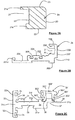
- the second frame element 2b which is preferably formed as a pultruded length of FRP, is shown in Figure 2B and is a substantially "J" shaped member having a leg part 201 and a foot part 202 extending from the leg part 201.
- the leg part 201 has a wall facing surface 203 which forms a part of the wall surface 2c.
- the obverse face 204 of the leg part 201 has plural elongate rebates 205 for accepting weather seals WS 1 , WS 2 .
- the leg part 201 Towards a distal end 201 d of the leg part 201, the leg part 201 thins to define an elongate slot 206, for receiving, where appropriate or desired, a part of a hinge H, for example friction hinge FH, to facilitate the opening and closing of the window 1.
- the foot part 202 comprises an interior facing surface 207 and an exterior facing surface 208. Extending away from the interior facing surface 207 is a return 209 which, together with the obverse face 204 of the leg part 201 defines an elongate rebate 211. Each of the return 209 and obverse face 204 carry facing abutment lips AL. An elongate cut-out 210 is provided at the connecting corner of the leg part 201 and foot part 202.
- the interior facing surface 207 of the foot part 202 abuts the opposite surface 23 of the first frame element 2a such that the second lip portion 21 b extends into the cut-out 210 and the first lip portion 21 aligns with the return 209, the lip portions 21 a, 21 b of the first frame element 2a thereby embracing the foot portion 202 of the second frame element 2b.
- the two frame elements 2a, 2b may be joined together by way of adhesives, screws, and/or other fasteners.
- the first lip portion 21 a obscures the view of the return 209 of the second frame element 2b.
- FIG. 2C there is shown a sash 3' configured to receive a triple glazing unit (not shown).
- the difference between the sash 3 of Figure 2 and the sash 3' of Figure 3 is the second sash element 3b and 3b', advantageously the first sash element 3a being identical in both cases.
- the first sash element 3a which may be formed from pultruded FRP, has an elongate limb 31 extending in a plane parallel to the wall surface 2c and having a wall surface facing side 31w and an obverse, glazing facing side 31g.
- the elongate limb 31 further comprises, at a distal end 31 d, a pair of orthogonal webs, 32a, 32b extending in opposite directions and providing an exterior surface 33.
- the glazing facing surface 31g being disposed between a channel 31c proximate one of the webs 32a and an abutment face 31f.
- the abutment face 31f will typically support a packer element.
- Each of the orthogonal webs 32a, 32b has, on a face obverse 34 to the exterior surface 33, an elongate slot 35 for carrying in each a weather seal WS 3 , WS 4 (see Figure 2 ).
- the proximal end 31 p of the elongate limb 31 has a pair of rebates 36 for receiving feet 303 of the second sash element 3b' (or indeed second sash element 3b as seen in Figure 2 ).
- the proximal end 31 p of the second sash element 3a also comprises an elongate cut-out 37. Between the distal and proximal ends 31 d, 31 p there is provided a slot 38 extending into the elongate limb 31 from the wall facing side 31w.
- the second sash element 3b' which may be formed from plastics material (e.g. PVC), wood of similar design or aluminium, preferably PVC, comprises a pair of facing legs 301', interconnected by a roof portion 302'.
- the second sash element 3b' may be formed from pultruded FRP although we have surprisingly found that pultruded FRP may make the section too stiff for some embodiments, for example embodiments where the window 1 is less than 600mm long.
- Each of the legs 301' terminate in a foot 303' for receipt in the rebates 36 of the first sash element 3a.
- the feet 303' snap fit in the rebates 36.
- An interior facing surface of the second sash element 3b' may comprise a decorative return 307'.
- the exterior facing surface of the second sash element 3b' may carry a rebate 303' for receipt of a weather seal WS 5 (see Figure 2 ).
- the second sash element 3b' is configured to allow receipt of a triple glazing unit in a window 1' of the invention.
- an extension 301e (as shown in Figure 2 ) it is a trivial matter to configure the window 1 for receipt of a double glazing unit.
- this realises the opportunity for glazing upgrades or changes as may be required, and also ensures that the minimum of components need be changed when making such an alteration.
- first frame element 2a and second frame element 2b are secured together and joined to form a peripheral frame 2 for receipt in an aperture, for example in a wall.
- the lengths are mitred or part-mitred (or alternatively not mitred) and joined together by adhesives and/or physical fixings.
- the so-formed frame 2 is configured for the first frame element 2a to provide the room facing portion of the frame 2 and for the second frame element 2b to provide the exterior-facing portion of the frame 2.
- the interior facing surface 207 of the foot part 202 of the second frame element 2b abuts the opposite surface 23 of the first frame element 2a such that the second lip portion 21 b extends into the cut-out 210 and the first lip portion 21 aligns with the return 209, the lip portions 21 a, 21 b of the first frame element 2a thereby embracing the foot portion 202 of the second frame element 2b.
- the two frame elements 2a, 2b may be joined together by way of adhesives, screws, and/or other fasteners.
- the first lip portion 21 a obscures the view of the return 209 of the second frame element 2b from the room facing side of the window 1.
- Weather seals WS 1 , WS 2 are located in rebates 205 around the entire internal-facing periphery of the frame 2.
- first sash element 3a Lengths of first sash element 3a are then secured together to form a framework as part of the sash 3.
- the pultruded lengths are mitred or part mitred (or alternatively not mitred) and joined together using adhesives, physical fixings and/or corner pieces.
- Weather seals WS 3 , WS 4 are located in rebates 35 around the entire periphery of the framework.
- a typical friction hinge HF can be used. This hinged joining may be performed by locating and securing a first part of the friction hinge FH in the rebate 206 of the second frame element 2b and a second part of the friction hinge FH in a facing rebate 38 of the first sash element 3a.
- the hinge parts of each friction hinge FH will engage side portions of the frame 2 and sash 3, rather than along the top side 2t or bottom side 2b.
- Figure 2 shows a friction hinge FH engaged within the respective rebates 206, 38.
- the frame 2 and hinged first sash element 3a may now be secured within a wall aperture using securing or adhesive compounds as are known in the art. Additionally or alternatively the frame 2 can be secured in place using physical fixings (nail, screws or so on).
- Glazing of the window 1 may take place either before or after the frame 2 is secured within an aperture.
- a glazing unit 4 (typically either a double glazed unit GU, Figure 2 , or triple glazed unit) is located within the sash framework.
- Packing (P, Figure 2 ) may be provided to ensure that the glazing unit 4 is appropriately located on the glazing facing surface 31 g of the first sash element 3a, and which packing P may be aligned by abutment with the abutment face 31f.
- a handle 5 is provided on the edge of the sash 3 opposite the pivot axis. As shown the handle 5 is secured to the sash 3 using a bracket B. In the alternative, the handle 5 may be located at any appropriate location.
- the window 1 comprises a lock 6, and preferably a slam lock (that being a lock which locks fast upon being closed and which requires further operation to disengage the same).
- the barrel 6a of the lock 6 is held within aperture 24 of the first frame element 2a and in elongate rebate 211 of the second frame element 2b with abutment lips AL providing an abutment surface for the lock barrel 6a.
- the locking component 6b is retained within the cut-out 37 of the first sash element 3a and may be retained by fasteners and/or may be held in place, at least in part, by the bracket B.
- the window 1 comprises a lock release lever 7 to release the lock 6 once the window 1 has been closed and the lock 6 has engaged.
- the lock release lever 7 may be of a different form or may be located elsewhere, such as within or on the handle 5.
- the frame 2 By fabricating the frame 2 in two parts it is possible to provide different internal and external finishes, thereby enabling the internal and external characteristics of the window to be matched to likely environmental conditions. Moreover, the use of FRP and timber allows the window components to be strong, thereby reducing the physical bulk of the frame 2 and sash 3 components. Indeed, we have found that the exterior sight line ESL of the window 1, as seen in Figure 3 may be less than 60 mm and can be less than 55 mm, that the interior sight line ISL may be less than 50 mm and can be less than 45 mm and the depth D of the window 1 can be less than 140 mm and may be less than 135 mm for a triple glazed window. A low sight line is beneficial because it allows more natural light into a room. This can have positive environmental effects in, say, cloudy or dim conditions because the use of artificial lighting may be reduced. A low sight line is also of benefit environmentally because a larger glass area improves the U value of the window 1.
- the window 1 is strong it facilitates security and allows robust locking components to be deployed.
- the lock body or mechanism 6 By locating the lock body or mechanism 6 in the frame 2, and specifically extending through the first frame element 2a and second frame element 2b, and by sizing the frame 2 appropriately, larger and more robust locks can be deployed than would otherwise be available, Because the lock mechanism is located or locatable in the frame 2 the sash 3 can be made smaller.
- the internal beading of the window 1 means that glazing 4 can be replaced or upgraded easily and from the inside of a building. This increases security and/or is of particular importance when the windows 1 are installed at elevated positions, for example in tower blocks or other multi-storey buildings because it obviates the need for lifting apparatus to access the window 1.
- the use of pultruded FRP on the exterior facing surfaces of the window 1 ensures a durability, excellent thermal performance and a long lifetime. Moreover, it can also be fabricated to provide Class 0 or Class 1 fire resistance (for example by choosing appropriate resin systems).
- the use of pultruded sections is also beneficial because thin walled pultrusion can be used to generate fine features, such as the weather seal rebates.
- the provision of five weather seals WS 1-5 ensures that the window 1 has excellent thermal performance.
- Our tests show that the U value of the windows 1 of the invention is as follows: Window Type U Value / Wm -L K -1 Centre Pane Value Window of Invention Double Glazed 1.0 1.0 - 1.15 (e.g. 1.08) Triple Glazed 0.5 0.5 - 0.8 (e.g. 0.65)
- windows of the invention can be fabricated as openable windows (e.g. Figure 2 ) and closed.
- Figure 4 shows a second frame element 2b' for use with a closed window 1. This can be deployed together with the first frame element 2a, as disclosed above.
- the second frame element 2b' which may be formed from timber or formed as a pultruded length of FRP, is shown in Figure 4 and is a substantially "J" shaped member having a leg part 201' and a foot part 202' extending from the leg part 201'.
- the leg part 201' has a wall facing surface 203' which forms a part of the wall surface 2c'.
- the obverse face 204' of the leg part 201' receives, in use, a first sash element 3a, as described previously.
- a distal end 201d' of the leg part 201' provides the exterior facing portion of the frame element.
- the distal end 201 d' may be treated to ensure that the timber is environmentally robust.
- a protective component can be secured to and/or over the distal end 201 d' to provide protection or the entire part 2b' may be treated to improve environmental protection.
- the foot part 202' comprises an interior facing surface 207' which abuts the opposite surface 23 of the first frame element 2a such that the second lip portion 21 b extends into a cut-out 210' and the first lip portion 21 aligns with an upper surface 209, the lip portions 21 a, 21 b of the first frame element 2a thereby embracing the foot portion 202' of the second frame element 2b.
- the two frame elements 2a, 2b' may be joined together by way of adhesives, screws, and/or other fasteners.
- the second frame element 2b' will be used along the bottom edge 2b of the window 1.
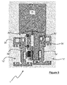
- FIG. 5 there is shown a window 1', similar to that shown in Figure 1 , in the region of a pillar PI between an opening window 1o' and a non-opening window 1c' (in both cases the glazing has been removed to improve visibility of the Figure).
- the opening window 1o' is shown as being slightly ajar.
- the first frame element 2a has been replaced by a pillar member PI which supports both a second frame element 2b' for the opening window 1o' and a second frame element 2b' for the non-opening window 1c'.
- the second frame elements 2b' support a first and second sash element 3a', 3b'
- the first of the second frame elements 2b' supports a sash element 3a' hingedly to facilitate and allow opening of the window 1o'
- the second frame elements 2b' supports a sash element 3a' fixedly to prevent the sash element 3a' from opening.
- a window of the invention 100 which is a variation of the window of Figure 2 (like numerals are used but with a prefix 6 for identification purposes.
- FIG. 6 Each of a frame 62, sash 63 and glazing 64 of the window 100 is shown in Figure 6 .
- the sash 63 carries a handle 65 secured thereto by a bracket B.
- the sash 63 and frame 62 each carry elements of a lock 66 and the frame 62 carries a lock release lever 67.
- the lock release lever may be incorporated into the handle 65, or may be absent or provided elsewhere.
- the frame 62 comprises a first frame element 62a and a second frame element 62b secured together, for example in the manner described above in respect to the embodiment shown in Figure 2 .
- the two frame elements 62a, 62b together provide a wall surface 62c defining a plane PL.
- the so-formed frame 62 is configured for the first frame element 62a to provide the room facing portion of the frame 62 and for the second frame element 62b to provide the exterior-facing portion of the frame 62.
- the sash 63 comprises a first sash element 63a and a second sash element 63b.
- the second sash element 63b includes an optional extension 6310e configured so that the first and second sash elements 63a, 63b may allow receipt of a double glazing unit GU.
- the window 100 comprises an opening sash 63o. Other configurations of window 100 are possible, for example multiple opening sashes 63o and/or one or more closed or fixed sashes.
- the sash 63 and frame 62 are joined together by way of hinges, for example friction hinges FH.
- Packing P may be provided to ensure that the glazing unit 4 is appropriately located on the glazing facing surface of the first sash element 3a.
- Weather seal WS 61 is located in a rebate around the entire internal-facing periphery of the frame 62.
- Weather seals WS 63 , WS 64 are located in rebates around the entire periphery of the framework.
- a weather seal WS65 may be received within a rebate in the exterior facing surface of the second sash element 3b.
- the lock 66 comprises a barrel held within aperture 624 of the first frame element 62a and in a rebate (not shown) of the second frame element 62b.
- the first frame element 62a further comprises a blind aperture 625 which communicates with aperture 624 and extends into the body of the first frame element 62a from the surface opposite to that into which aperture 624 extends.
- the principal difference between the embodiment shown in Figure 2 and that shown in Figure 6 is the location of one of the weather seals (WS 2 in Figure 2 and WS 62 in Figure 6 ).
- the weather seal WS 62 has been moved such that it bears between second sash element 63b and frame 62. This, surprisingly, helps with the opening of the window in some embodiments whilst not affecting the thermal performance.
- the window 100 shown in Figure 6 may be assembled as described above in respect of the embodiment shown in Figure 2 .
- Figure 7 shows a window 61' in the region of a pillar PI', having an opening sash 610' and a fixed sash 61c'.
- the opening sash 610' is identical to that shown in Figure 6 with the second weather seal WS 62 ' located between the pillar PI' and the second sash element 63b'.
- the opening sash 610' comprises a second frame element 62b'.
- the fixed sash 61 c' may comprise, as a second frame element 62b", a wooden member or a plastics member.
- the second frame elements 62b', 62b" support the first and second sash element 63a', 63b'.
- the first of the second frame elements 62b' supports a sash element 63a' hingedly to facility and allow opening of the window.
- the second of the second frame elements 62b" supports a sash element 63a' fixedly to prevent opening of the window.
- the window 1 of the invention provides a robust window which can have an extremely long life, which providing excellent performance. Moreover the window 1 can be secure and can be adapted to provide plural aesthetic finishes whilst not compromising performance.
Landscapes
- Engineering & Computer Science (AREA)
- Civil Engineering (AREA)
- Structural Engineering (AREA)
- Wing Frames And Configurations (AREA)
- Door And Window Frames Mounted To Openings (AREA)
Applications Claiming Priority (1)
| Application Number | Priority Date | Filing Date | Title |
|---|---|---|---|
| GBGB1513341.6A GB201513341D0 (en) | 2015-07-29 | 2015-07-29 | Windows |
Publications (1)
| Publication Number | Publication Date |
|---|---|
| EP3124731A1 true EP3124731A1 (fr) | 2017-02-01 |
Family
ID=54106781
Family Applications (1)
| Application Number | Title | Priority Date | Filing Date |
|---|---|---|---|
| EP16275108.5A Withdrawn EP3124731A1 (fr) | 2015-07-29 | 2016-07-29 | Fenêtres |
Country Status (2)
| Country | Link |
|---|---|
| EP (1) | EP3124731A1 (fr) |
| GB (2) | GB201513341D0 (fr) |
Cited By (1)
| Publication number | Priority date | Publication date | Assignee | Title |
|---|---|---|---|---|
| CN106948717A (zh) * | 2017-04-01 | 2017-07-14 | 浙江瑞明节能科技股份有限公司 | 一种铝木复合金刚网一体式外开窗 |
Citations (3)
| Publication number | Priority date | Publication date | Assignee | Title |
|---|---|---|---|---|
| GB1514666A (en) * | 1975-09-18 | 1978-06-21 | Superseal Corp | Window assemblies |
| DE202008015176U1 (de) * | 2008-11-15 | 2009-02-19 | Espeter, Reiner | Zarge für eine Tür |
| WO2010117345A2 (fr) * | 2009-04-09 | 2010-10-14 | Ahmet Cihat Esen | Portes et fenetres en bois a l'interieur et pvc a l'exterieur |
Family Cites Families (2)
| Publication number | Priority date | Publication date | Assignee | Title |
|---|---|---|---|---|
| DE2819916C3 (de) * | 1978-05-06 | 1980-10-16 | Wieland-Werke Ag, 7900 Ulm | Feststehender Metallrahmen für horizontal bewegbare Schiebefenster oder Schiebetüren |
| CN202131890U (zh) * | 2010-11-29 | 2012-02-01 | 欧创塑料建材(浙江)有限公司 | 复合式节能窗 |
-
2015
- 2015-07-29 GB GBGB1513341.6A patent/GB201513341D0/en not_active Ceased
-
2016
- 2016-07-29 GB GB1613099.9A patent/GB2542684A/en not_active Withdrawn
- 2016-07-29 EP EP16275108.5A patent/EP3124731A1/fr not_active Withdrawn
Patent Citations (3)
| Publication number | Priority date | Publication date | Assignee | Title |
|---|---|---|---|---|
| GB1514666A (en) * | 1975-09-18 | 1978-06-21 | Superseal Corp | Window assemblies |
| DE202008015176U1 (de) * | 2008-11-15 | 2009-02-19 | Espeter, Reiner | Zarge für eine Tür |
| WO2010117345A2 (fr) * | 2009-04-09 | 2010-10-14 | Ahmet Cihat Esen | Portes et fenetres en bois a l'interieur et pvc a l'exterieur |
Cited By (1)
| Publication number | Priority date | Publication date | Assignee | Title |
|---|---|---|---|---|
| CN106948717A (zh) * | 2017-04-01 | 2017-07-14 | 浙江瑞明节能科技股份有限公司 | 一种铝木复合金刚网一体式外开窗 |
Also Published As
| Publication number | Publication date |
|---|---|
| GB201513341D0 (en) | 2015-09-09 |
| GB2542684A (en) | 2017-03-29 |
| GB201613099D0 (en) | 2016-09-14 |
Similar Documents
| Publication | Publication Date | Title |
|---|---|---|
| US8561365B2 (en) | Versatile hybrid window system | |
| US6367201B1 (en) | Width adaptable threshold assembly | |
| US20110047881A1 (en) | Window assembly | |
| US11619090B1 (en) | Composite fenestration assembly | |
| US20120031023A1 (en) | Frame construction for a fenestration | |
| US6263626B1 (en) | Window and door sash with interior wood covering | |
| US7836643B2 (en) | Window | |
| US7765741B2 (en) | Movable light latch | |
| EP3124731A1 (fr) | Fenêtres | |
| AT502544A2 (de) | Fenster mit abdeckblende, abdeckblende, verwendung einer abdeckblende und system für fenster oder türen | |
| US11634941B2 (en) | Window/shutter/door for outdoor settings | |
| EP2105569A1 (fr) | Ensemble de fenêtre | |
| US20090301005A1 (en) | Composite structure for window sash, door frame, and the like | |
| US8359795B2 (en) | Window cladding | |
| EP2975206B1 (fr) | Profil renforcé pour cadres de châssis et ensemble de profils pour cadres de châssis et de fenêtre | |
| CN224187421U (zh) | 一种窄边式门窗结构及门窗 | |
| US20230193687A1 (en) | Coastal weather window and door system with interior mounting assembly | |
| AU2006228089B2 (en) | Window sash and window assembly | |
| EP1640547A1 (fr) | Procédé de fixation d'un élément de couverture à un cadre de fenêtre et élément de couverture | |
| EP3740640B1 (fr) | Battant sans cadre avec profilé en u | |
| EP1643069A2 (fr) | Cadre pour fenêtres, portes-fenêtres et similaires | |
| WO2004027194A1 (fr) | Structure de fenetre ou de porte dans laquelle une cavite est menagee entre le chassis et le cadre principal | |
| AU2023216872A1 (en) | Closure framing system | |
| US20080005968A1 (en) | Shutter assembly | |
| CN106978960A (zh) | 一种横梁立柱连接幕墙用提升推拉门 |
Legal Events
| Date | Code | Title | Description |
|---|---|---|---|
| PUAI | Public reference made under article 153(3) epc to a published international application that has entered the european phase |
Free format text: ORIGINAL CODE: 0009012 |
|
| AK | Designated contracting states |
Kind code of ref document: A1 Designated state(s): AL AT BE BG CH CY CZ DE DK EE ES FI FR GB GR HR HU IE IS IT LI LT LU LV MC MK MT NL NO PL PT RO RS SE SI SK SM TR |
|
| AX | Request for extension of the european patent |
Extension state: BA ME |
|
| STAA | Information on the status of an ep patent application or granted ep patent |
Free format text: STATUS: THE APPLICATION IS DEEMED TO BE WITHDRAWN |
|
| 18D | Application deemed to be withdrawn |
Effective date: 20170802 |