EP3124745B1 - Turbomaschinenkomponente mit filmgekühlter wand - Google Patents
Turbomaschinenkomponente mit filmgekühlter wand Download PDFInfo
- Publication number
- EP3124745B1 EP3124745B1 EP15178849.4A EP15178849A EP3124745B1 EP 3124745 B1 EP3124745 B1 EP 3124745B1 EP 15178849 A EP15178849 A EP 15178849A EP 3124745 B1 EP3124745 B1 EP 3124745B1
- Authority
- EP
- European Patent Office
- Prior art keywords
- coolant
- coolant discharge
- wall
- duct
- discharge duct
- Prior art date
- Legal status (The legal status is an assumption and is not a legal conclusion. Google has not performed a legal analysis and makes no representation as to the accuracy of the status listed.)
- Active
Links
Images


Classifications
-
- F—MECHANICAL ENGINEERING; LIGHTING; HEATING; WEAPONS; BLASTING
- F01—MACHINES OR ENGINES IN GENERAL; ENGINE PLANTS IN GENERAL; STEAM ENGINES
- F01D—NON-POSITIVE DISPLACEMENT MACHINES OR ENGINES, e.g. STEAM TURBINES
- F01D5/00—Blades; Blade-carrying members; Heating, heat-insulating, cooling or antivibration means on the blades or the members
- F01D5/12—Blades
- F01D5/14—Form or construction
- F01D5/18—Hollow blades, i.e. blades with cooling or heating channels or cavities; Heating, heat-insulating or cooling means on blades
- F01D5/187—Convection cooling
-
- F—MECHANICAL ENGINEERING; LIGHTING; HEATING; WEAPONS; BLASTING
- F01—MACHINES OR ENGINES IN GENERAL; ENGINE PLANTS IN GENERAL; STEAM ENGINES
- F01D—NON-POSITIVE DISPLACEMENT MACHINES OR ENGINES, e.g. STEAM TURBINES
- F01D5/00—Blades; Blade-carrying members; Heating, heat-insulating, cooling or antivibration means on the blades or the members
- F01D5/12—Blades
- F01D5/14—Form or construction
- F01D5/18—Hollow blades, i.e. blades with cooling or heating channels or cavities; Heating, heat-insulating or cooling means on blades
- F01D5/186—Film cooling
-
- F—MECHANICAL ENGINEERING; LIGHTING; HEATING; WEAPONS; BLASTING
- F01—MACHINES OR ENGINES IN GENERAL; ENGINE PLANTS IN GENERAL; STEAM ENGINES
- F01D—NON-POSITIVE DISPLACEMENT MACHINES OR ENGINES, e.g. STEAM TURBINES
- F01D25/00—Component parts, details, or accessories, not provided for in, or of interest apart from, other groups
- F01D25/08—Cooling; Heating; Heat-insulation
- F01D25/12—Cooling
-
- F—MECHANICAL ENGINEERING; LIGHTING; HEATING; WEAPONS; BLASTING
- F01—MACHINES OR ENGINES IN GENERAL; ENGINE PLANTS IN GENERAL; STEAM ENGINES
- F01D—NON-POSITIVE DISPLACEMENT MACHINES OR ENGINES, e.g. STEAM TURBINES
- F01D5/00—Blades; Blade-carrying members; Heating, heat-insulating, cooling or antivibration means on the blades or the members
- F01D5/12—Blades
- F01D5/14—Form or construction
- F01D5/18—Hollow blades, i.e. blades with cooling or heating channels or cavities; Heating, heat-insulating or cooling means on blades
- F01D5/182—Transpiration cooling
- F01D5/183—Blade walls being porous
-
- F—MECHANICAL ENGINEERING; LIGHTING; HEATING; WEAPONS; BLASTING
- F01—MACHINES OR ENGINES IN GENERAL; ENGINE PLANTS IN GENERAL; STEAM ENGINES
- F01D—NON-POSITIVE DISPLACEMENT MACHINES OR ENGINES, e.g. STEAM TURBINES
- F01D5/00—Blades; Blade-carrying members; Heating, heat-insulating, cooling or antivibration means on the blades or the members
- F01D5/12—Blades
- F01D5/14—Form or construction
- F01D5/18—Hollow blades, i.e. blades with cooling or heating channels or cavities; Heating, heat-insulating or cooling means on blades
- F01D5/185—Liquid cooling
-
- F—MECHANICAL ENGINEERING; LIGHTING; HEATING; WEAPONS; BLASTING
- F01—MACHINES OR ENGINES IN GENERAL; ENGINE PLANTS IN GENERAL; STEAM ENGINES
- F01D—NON-POSITIVE DISPLACEMENT MACHINES OR ENGINES, e.g. STEAM TURBINES
- F01D9/00—Stators
- F01D9/02—Nozzles; Nozzle boxes; Stator blades; Guide conduits, e.g. individual nozzles
-
- F—MECHANICAL ENGINEERING; LIGHTING; HEATING; WEAPONS; BLASTING
- F05—INDEXING SCHEMES RELATING TO ENGINES OR PUMPS IN VARIOUS SUBCLASSES OF CLASSES F01-F04
- F05D—INDEXING SCHEME FOR ASPECTS RELATING TO NON-POSITIVE-DISPLACEMENT MACHINES OR ENGINES, GAS-TURBINES OR JET-PROPULSION PLANTS
- F05D2220/00—Application
- F05D2220/30—Application in turbines
- F05D2220/32—Application in turbines in gas turbines
-
- F—MECHANICAL ENGINEERING; LIGHTING; HEATING; WEAPONS; BLASTING
- F05—INDEXING SCHEMES RELATING TO ENGINES OR PUMPS IN VARIOUS SUBCLASSES OF CLASSES F01-F04
- F05D—INDEXING SCHEME FOR ASPECTS RELATING TO NON-POSITIVE-DISPLACEMENT MACHINES OR ENGINES, GAS-TURBINES OR JET-PROPULSION PLANTS
- F05D2240/00—Components
- F05D2240/80—Platforms for stationary or moving blades
- F05D2240/81—Cooled platforms
-
- F—MECHANICAL ENGINEERING; LIGHTING; HEATING; WEAPONS; BLASTING
- F05—INDEXING SCHEMES RELATING TO ENGINES OR PUMPS IN VARIOUS SUBCLASSES OF CLASSES F01-F04
- F05D—INDEXING SCHEME FOR ASPECTS RELATING TO NON-POSITIVE-DISPLACEMENT MACHINES OR ENGINES, GAS-TURBINES OR JET-PROPULSION PLANTS
- F05D2260/00—Function
- F05D2260/20—Heat transfer, e.g. cooling
-
- F—MECHANICAL ENGINEERING; LIGHTING; HEATING; WEAPONS; BLASTING
- F05—INDEXING SCHEMES RELATING TO ENGINES OR PUMPS IN VARIOUS SUBCLASSES OF CLASSES F01-F04
- F05D—INDEXING SCHEME FOR ASPECTS RELATING TO NON-POSITIVE-DISPLACEMENT MACHINES OR ENGINES, GAS-TURBINES OR JET-PROPULSION PLANTS
- F05D2260/00—Function
- F05D2260/20—Heat transfer, e.g. cooling
- F05D2260/202—Heat transfer, e.g. cooling by film cooling
-
- F—MECHANICAL ENGINEERING; LIGHTING; HEATING; WEAPONS; BLASTING
- F05—INDEXING SCHEMES RELATING TO ENGINES OR PUMPS IN VARIOUS SUBCLASSES OF CLASSES F01-F04
- F05D—INDEXING SCHEME FOR ASPECTS RELATING TO NON-POSITIVE-DISPLACEMENT MACHINES OR ENGINES, GAS-TURBINES OR JET-PROPULSION PLANTS
- F05D2260/00—Function
- F05D2260/20—Heat transfer, e.g. cooling
- F05D2260/204—Heat transfer, e.g. cooling by the use of microcircuits
-
- F—MECHANICAL ENGINEERING; LIGHTING; HEATING; WEAPONS; BLASTING
- F05—INDEXING SCHEMES RELATING TO ENGINES OR PUMPS IN VARIOUS SUBCLASSES OF CLASSES F01-F04
- F05D—INDEXING SCHEME FOR ASPECTS RELATING TO NON-POSITIVE-DISPLACEMENT MACHINES OR ENGINES, GAS-TURBINES OR JET-PROPULSION PLANTS
- F05D2260/00—Function
- F05D2260/20—Heat transfer, e.g. cooling
- F05D2260/231—Preventing heat transfer
Definitions
- the present disclosure relates to a turbo-engine component as set forth in claim 1.
- a layer of relatively cooler fluid is provided flowing along the surfaces of the components which are exposed to a hot working fluid flow.
- ducts are provided in walls of the component opening out on a hot gas exposed surface of hot gas exposed walls of the component (see for example AT 404160 , US 8,851,848 or US 8,591,191 ). Said ducts are inclined with respect to a normal of the hot gas exposed surface, or hot gas side surface, of the wall.
- the ducts are in particular inclined into the main direction of the working fluid flowing along the component such as to discharge the film cooling fluid with a velocity component parallel to that of the working fluid, and tangential to the hot gas exposed surface, such that said layer of film cooling fluid is provided.
- the cooling effect becomes the more uniform the more uniform the distribution of cooling fluid on the hot gas exposed surface is.
- the distribution becomes more uniform as more holes are used.
- US 2001/0016162 (as also EP 2143882 , US 5,392,515 or EP2540972 ) proposes non-penetrating coolant discharge ducts which are in fluid communication with a coolant supply path provided inside the wall.
- the coolant supply path comprises a near wall cooling duct.
- counterflow convective cooling is effected.
- Temperature distribution on the hot gas exposed surface of the turbo-engine component thus is rendered more uniform.
- US 7,766,618 proposes to provide the coolant discharge ducts as slots with a slot longitudinal direction extending across the main working fluid flow direction.
- the coolant discharge ducts are shaped as blind cavities and are closed towards a coolant side of the wall.
- a multitude of coolant discharge ducts join at the hot gas exposed surface in order to provide a common coolant discharge slot with a longitudinal axis oriented across the flow direction of a main working fluid flow.
- it is expected to achieve a coolant flow dispersed over the hot gas exposed surface across the main working fluid flow direction.
- the coolant discharge ducts join immediately adjacent the hot gas exposed surface, still a largely non-uniform coolant distribution on the hot gas side surface is supposed.
- improved cooling of the component is to be achieved.
- effective use of the coolant is to be provided for.
- a more uniform cooling of and in turn temperature distribution in a hot gas exposed wall of a turbo-engine component shall be achieved.
- the distribution of coolant on a hot gas exposed surface and across a main working fluid flow direction shall be improved.
- the film cooling features shall be provided such as to maintain sufficient material such as not to compromise the structural integrity of the component.
- a turbo-engine component comprising a wall, the wall comprising a hot gas side surface and a coolant side surface, wherein at least one coolant discharge duct is provided in said wall and opening out onto the hot gas side surface at a coolant discharge opening.
- a coolant flow direction of the coolant discharge duct is defined from the interior of the coolant discharge duct towards the discharge opening.
- the coolant discharge duct is delimited by a delimiting surface thereof, provided as an inner surface of the wall.
- the coolant discharge duct has a first cross sectional direction and a second cross sectional direction. In particular, the first and second cross sectional directions may be perpendicular to each other.
- cross sectional directions are oriented across and in particular at least essentially perpendicular to the coolant flow direction as defined above. It will be appreciated, that further in particular said cross sectional directions may span up a flow cross section of the coolant discharge duct.
- the coolant discharge duct is a blind cavity and is closed towards the coolant side surface.
- a dimension of the coolant discharge duct measured across the coolant discharge duct and in the first cross sectional direction decreases in the coolant flow direction.
- the coolant discharge duct tapers when considering the dimension of the coolant discharge duct measured across the coolant discharge duct in the first cross sectional direction.
- Said contouring of the coolant discharge duct flow cross section for the coolant to be discharged provides for the capability to influence the flow field of the discharged coolant. Such, for instance, a more homogenous distribution of the coolant discharge flow on a hot gas exposed surface of the component may be achieved.
- a dimension of the coolant discharge duct measured across the coolant discharge duct and in the first cross sectional direction decreases in the coolant flow direction
- a dimension of the coolant discharge duct measured across the coolant discharge duct and in the second cross sectional direction increases in the coolant flow direction.
- the coolant discharge duct tapers when considering the dimension of the coolant discharge duct measured across the coolant discharge duct in the first cross sectional direction, and widens when considering the dimension of the coolant discharge duct measured across the coolant discharge duct and in the second cross sectional direction.
- the flow field of the coolant discharged therefrom onto the hot gas side surface may be adjusted.
- the contouring of the coolant discharge duct may be chosen such that the flow is evenly distributed over the wider dimension of the duct at the discharge location on the hot gas side surface.
- the contouring may be chosen such that an even velocity distribution of the discharged coolant upon exit from the coolant discharge duct is achieved along the second cross sectional direction.
- the tapering geometry of the coolant discharge duct in the first direction in turn serves to adjust the mean velocity of the coolant emanating from the coolant discharge duct while it widens in the second direction.
- Said cooperating tapering of the coolant discharge duct in one cross sectional direction and widening in another cross sectional direction may serve to adjust the flow cross section accordingly.
- Providing the coolant supply duct as a blind cavity, not completely penetrating the wall, may serve to improve mechanical strength and preserve structural integrity of the component and in turn to enhance service lifetime. Due to the fact that the coolant discharge channel is non-penetrating, which is in the frame of this document to be understood as not entirely penetrating the wall from the hot gas side surface to the coolant side surface, sufficient material is preserved even with comparatively large cross section coolant discharge ducts. Moreover, by virtue of shaping the coolant discharge duct such that its dimension increases along one cross sectional direction while decreasing in another cross sectional direction, the reduction of the material strength may not be locally concentrated, which would result in peak stresses, but may be distributed over a larger volume.
- the coolant discharge duct may be shaped such that the flow cross section provided by the coolant discharge duct for the flow of the coolant to be discharged decreases in the coolant flow direction.
- the coolant discharge duct cross sectional flow area for the coolant flow tapers. The coolant flow is accelerated in the coolant discharge duct. Flow separation of the coolant discharge flow from the contoured delimiting surfaces of the coolant discharge duct may thus be effectively avoided.
- the first cross sectional direction extends in a main working fluid flow direction on the hot gas side of the wall.
- the component is intended for a specific use, and thus the main working fluid flow direction is a well-defined orientation of the component, and/or a hot gas exposed wall thereof, respectively.
- the component may for instance be, but not limited to, a blade, vane, airfoil, platform, heat shield and the like, having an aerodynamic shape and/or fixation means which relate to the intended main working fluid flow direction in a unique manner.
- the coolant discharge opening is a slot with a longitudinal extent of the slot being provided along the second cross sectional direction.
- the slot may be straight or curved.
- the coolant is discharged through the slot, in the form of a thin layer of coolant emanating from the slot and extending along the second cross sectional direction.
- said layer of emanating coolant is provided across the main working fluid flow direction and thus results in a more homogeneous coolant layer across the main working fluid flow direction.
- the coolant discharge duct may be slanted or, in another aspect, may be inclined with respect to a normal of the hot gas side surface at a first angle.
- the coolant flow direction accordingly has a directional component oriented tangentially to the hot gas side surface of the wall, supporting film cooling as lined out above.
- the coolant discharged from the coolant discharge duct accordingly has a velocity component oriented parallel to the hot gas side surface of the wall.
- a direction of the coolant discharge duct may be defined by an axis thereof.
- an orientation of delimiting surfaces of the coolant discharge duct may be said to define said orientation and in turn said inclination.
- a mean orientation of the delimiting surfaces of the coolant discharge duct may be said to define said orientation and in turn said inclination.
- a lateral delimiting surface of the coolant discharge duct accordingly comprises a first surface section disposed towards the hot gas side surface of the wall and a second surface section disposed towards the coolant side surface of the wall.
- the inclination may in certain embodiments be provided in a plane defined by the first cross sectional direction and said normal. It may then be said that said first angle is located in a plane defined by the first cross sectional direction and the normal.
- the coolant discharge opening is a slot with the long side of the slot being oriented along the second cross sectional direction of the coolant discharge duct
- a coolant layer is discharged with a plain surface of the layer being slanted towards the hot gas side surface, further supporting film cooling.
- said inclination may be directed downstream a main working fluid flow direction of the component along the coolant flow direction. It may then be said that said first angle is located in a plane defined by the main working fluid flow direction and the normal. It may in this case, in another point of view, be said that an orientation of the coolant discharge duct along or tangential to the hot gas side surface, or, the direction into which a coolant discharge duct is slanted, defines the main working fluid flow direction.
- the coolant discharged from the coolant discharge duct in this embodiment is slanted towards the downstream direction of the main working fluid flow direction. That is, the discharged coolant flow is oriented at least with a velocity component thereof in parallel with the main working fluid flow direction.
- the coolant discharge opening is provided as a slot, with the long side of the slot oriented across the main working fluid flow direction, a layer of coolant is effectively dispersed across the main working fluid flow direction.
- the first delimiting surface section of the coolant discharge duct is disposed towards the hot gas side surface of the wall, and upstream with respect to the main working fluid flow direction, while a second delimiting surface section is disposed towards the coolant side surface of the wall and downstream with respect to the main working fluid flow direction.
- the coolant discharge duct is delimited by a delimiting surface, the delimiting surface comprising a first surface section disposed towards the hot gas side surface and a second surface section disposed towards the coolant side surface, wherein at least one of the first and second surface sections comprises a flat surface section.
- Said embodiment supports and facilitates providing a slot-shaped coolant discharge opening.
- the component further comprises a coolant supply path provided in the wall and in fluid communication with the coolant discharge duct, wherein the coolant supply path joins the coolant discharge duct at a lateral delimiting surface of the coolant discharge duct and at a nonzero angle.
- coolant can be supplied to the coolant discharge duct, while providing the coolant supply duct closed towards the coolant side of the wall.
- coolant flowing out from the coolant supply path and into the coolant discharge duct may be discharged from the coolant supply path and into the coolant discharge duct such as to effect impingement cooling of an opposed delimiting surface section.
- the nonzero angle may be at least approximately 90 degrees, and may be in particular 70 degrees or larger, related to the surface at which the coolant supply path joins the coolant discharge duct, or related to the coolant discharge direction.
- the coolant supply path may join the coolant discharge duct through an opening provided in a lateral delimiting surface section of the coolant discharge duct disposed on a downstream side with respect to a main working fluid flow direction. This supports impingement cooling of a surface section of the coolant discharge duct disposed upstream with respect to the main working fluid flow direction. More specifically, the coolant supply path may join the coolant discharge duct at a certain distance from the blind end, or upstream end with respect to the coolant discharge flow direction of the coolant discharge duct. This enables the impingement cooling free jet emanating from the coolant supply path and into the coolant discharge duct to more uniformly disseminate over a surface on which it impinges.
- a coolant supply opening, or a nozzle, through which the coolant supply path joins the coolant discharge duct has a size in the coolant flow direction, or, in specific embodiments, a diameter.
- a lower or upstream edge of said coolant supply opening is spaced from a blind or upstream end of the coolant discharge duct by a distance, which is in certain embodiments larger than or equal to 50% of said coolant supply opening size or diameter, and in still further embodiments larger than or equal to 70% of said coolant supply opening size or diameter.
- a center of the coolant supply opening when seen along the coolant flow direction, is spaced apart from the blind or upstream end of the coolant discharge duct by a distance which is larger than or equal to said coolant supply opening size or diameter, and is more particularly larger than or equal to 1.2 times said coolant supply opening size or diameter. Impingement cooling effectiveness is improved.
- the coolant supply path joins the coolant discharge duct through an opening provided in a lateral delimiting surface section thereof disposed towards the coolant side surface of the wall.
- impingement cooling of a lateral delimiting surface of the coolant discharge duct disposed towards the hot gas side surface of the wall is supported.
- Adjacent said hot gas side disposed surface section of the surface delimiting the coolant discharge duct only a small wall thickness may be present between the delimiting surface of the coolant discharge duct and the hot gas side surface.
- said wall section may not fully benefit from the film cooling layer emanating from the coolant discharge duct, if it is located at an upstream location with respect to the main working fluid flow. This wall section may thus be particularly vulnerable to heat intake from the working fluid flow.
- a remedy for this situation is provided according to the present disclosure in providing the junction of the coolant supply path and the coolant discharge duct at a lateral delimiting surface of the coolant discharge duct which is disposed towards the coolant side surface, thus discharging the coolant supply flow from the coolant supply path, and directing the coolant supply flow onto said surface section of the coolant discharge duct which is disposed towards the hot gas side surface of the wall. Thus impingement cooling of the respective wall section is affected.
- a means for providing a free jet emanating from the coolant supply path and into the coolant discharge duct is provided.
- Said means is in particular provided as a flow accelerating section of the coolant supply path provided at or adjacent to the junction of the coolant supply path and the coolant discharge duct. In accelerating the coolant supply flow prior to or upon entry into the coolant discharge duct, a high impulse jet is generated across the coolant discharge duct which impinges on a opposed delimiting surface section of the coolant discharge duct and effectively effects impingement cooling.
- the flow accelerating section may be shaped as a nozzle provided at the junction of the coolant supply path and the coolant discharge duct.
- the coolant supply path may be provided as a duct having a first flow cross section which tapers to a throat having a smaller cross section at or adjacent to the junction of the coolant supply path and the coolant discharge duct.
- junction of the coolant supply path and the coolant supply duct may be provided such as to provide a free jet emanating from the free jet generating means in a jet direction having at least one of a velocity component oriented from the coolant side surface of the wall and towards the hot gas side surface of the wall, and/or oriented upstream the main working fluid flow direction.
- the coolant supply path may be in fluid communication with a coolant supply volume provided adjacent the coolant side surface of the wall such as to provide a coolant flow from said supply volume to the coolant discharge duct.
- the coolant supply path comprises a near wall cooling duct running inside the wall along a lengthwise extent of the wall.
- a lengthwise extent of the wall is in this respect will be understood as extending between and along, or essentially aligned with, the hot gas side surface of the wall and the coolant side surface of the wall. In certain aspects it may be understood as parallel to at least one of the hot gas side surface and the coolant side surface. In specific aspects it may be understood as extending at least essentially parallel to the main working fluid flow direction.
- the near wall cooling duct extends from a first end thereof to a second end thereof, wherein a means for providing a free jet, as in particular embodiments a nozzle, or, more generally, a flow acceleration means, is disposed adjacent the second end of the near wall cooling duct.
- the first end of the near wall cooling duct is disposed downstream of the second end of the near wall cooling duct with respect to the main working fluid flow direction.
- convective counterflow near wall cooling is effected before the coolant supply flow is discharged from the coolant supply path into the coolant discharge duct.
- the near wall cooling duct in further embodiments, runs at least essentially in parallel to the hot gas side surface.
- the internal surfaces of the near wall cooling duct may be shaped such as to improve heat transfer between the surfaces of the near wall cooling duct and the coolant supply flow therethrough, and/or may be equipped with elements enhancing heat transfer.
- any means known to the skilled person which intensify heat transfer between the surfaces delimiting the near wall cooling duct and the coolant flow therethrough may be applied, such as, but not limited to, posts connecting opposed surfaces, the delimiting surfaces of the near wall cooling duct may be undulating, and so forth.
- turbulence generating elements are provided within the near wall cooling duct and on a delimiting surface thereof.
- a coolant inflow duct is provided extending between the coolant side surface of the wall and the near wall cooling duct, and joins the near wall cooling duct at a sidewall thereof, wherein the junction is provided at or adjacent the first end of the near wall cooling duct, and is in particular provided on a side of the near wall cooling duct disposed towards the coolant side surface of the wall.
- a free jet generating means similar to that described above at or adjacent to the junction of the coolant supply path and the coolant discharge duct, is disposed adjacent to or at the junction of the coolant inflow duct and the near wall cooling duct.
- the free jet impinges on an opposed delimiting surface section of the near wall cooling duct which is disposed towards the hot gas side surface.
- a wall section of the component at this surface section may be disposed comparatively far downstream the coolant discharge location on the hot gas side surface, again related to the main working fluid flow direction, and may thus be subject to comparatively high thermal loading.
- an extent of the near wall cooling duct across and along the main working fluid flow direction may be chosen larger than a cross sectional extent in a direction between the coolant side surface and the hot gas side surface.
- the turbo-engine component as herein disclosed may comprise two or more coolant discharge ducts of the kind disclosed above provided in a wall of the turbo-engine component, wherein said at least two coolant discharge ducts are each provided with a coolant discharge opening provided towards the hot gas side surface of the wall.
- Each of said coolant discharge openings has a cross section, wherein said cross section exhibits a first extent in a first direction being smaller than a second extent in a second direction.
- the coolant discharge openings are arranged such that short edges of two neighboring coolant discharge openings are disposed adjacent each other. A distance between adjacent short edges of neighboring coolant discharge openings may be substantially smaller than the - longer - extent of each coolant discharge opening in the second direction.
- Said distance between two adjacent short edges may be 50% or less, 40% or less, 30% or less, 20% or less, and in particular 10% or less of the extent of each of the adjacent coolant discharge openings in the second direction.
- the respective coolant discharge ducts may be inclined in the first direction of the coolant discharge openings. Further, the coolant discharge ducts may be slanted downstream the main working fluid flow direction.
- the coolant discharge openings may be aligned with each other along the second direction. That is, in other words, a row of, in particular slot-shaped, coolant discharge openings are provided on the hot gas side surface of the wall, with the long extents of the coolant discharge openings being at least substantially aligned with each other. In other embodiments, however, the coolant discharge openings may be arranged such as to form a zig-zag, or in an undulating manner. As will be appreciated, by virtue of said arrangement of coolant discharge openings, a multitude of coolant layers or sheets are discharged from on the hot gas side surface, wherein each layer or sheet extends across the first cross sectional direction.
- the coolant discharge ducts are aligned with the first cross sectional direction along the main working fluid flow direction, and the coolant discharge ducts are inclined such that the coolant is discharged with a velocity component directed downstream the main working fluid flow direction.
- the coolant is thus effectively dispersed across the main working fluid flow direction and downstream the coolant discharge openings on the hot gas side surface of the wall, thus providing for superior film cooling effectiveness and efficiency.
- a multitude of arrangements of adjacent coolant discharge openings may be provided and staggered in the first direction and/or in the main working fluid flow direction.
- At least two coolant discharge openings adjoin each other at short edges thereof such as to provide a common coolant discharge opening of said at least two coolant discharge ducts.
- certain embodiments of the disclosed subject matter may require complex duct geometries to be provided inside the wall of the component. Said ducts may not or may only expensively be manufactured by chip removing methods.
- the component may be thus in particular be obtained by high precision casting.
- the component may be obtained by additive production methods, such as, but not limited to, selective laser melting or selective electron beam melting.
- gas turbine engine comprising a turbo-engine component as described above.
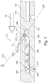
- Figure 1 shows an embodiment of a wall 100 of a turbo-engine component.
- the wall 100 comprises a hot gas side surface 110 and a coolant side surface 120.
- the hot gas side surface 110 is intended, when the component is installed in a turbo-engine, and the turbo-engine is operated, to be exposed to a working fluid flow 50.
- the component is in particular intended to be installed in the turbo-engine such that the working fluid flow flows along the hot gas side surface 110 of the component wall 100 in a main working fluid flow direction indicated by the arrow at 50, into a main working fluid flow downstream direction. It is to this extent possible to define an upstream and a downstream direction of the component, or the wall 100, respectively, related to the main working fluid flow direction.
- the working fluid flow 50 may be present at elevated temperatures, for instance in an expansion turbine of a gas turbine engine.
- components installed in the first stages of such an expansion turbine thus require cooling.
- a coolant discharge duct 210 is provided in the wall 100. Coolant discharge duct 210 is delimited by a delimiting surface provided inside the wall 100. An axis 213 of the coolant discharge duct is inclined with respect to a normal 111 of the hot gas side surface 110 at an angle a, and is slanted towards the downstream direction of the working fluid main flow when considering an orientation of the coolant discharge duct 210 from inside the wall to a discharge opening provided on the hot gas side surface.
- a first section 211 of the delimiting surface and a second section 212 of the delimiting surface are inclined with respect to the normal, and slanted towards a downstream orientation of the main working fluid flow direction.
- wall 100 may be curved, and consequently the hot gas side surface 110 may be curved.
- a local normal at a location where the fluid discharge duct opens out onto the hot gas side surface that is, a discharge location, will be applied for the definition of said normal, or said inclination, respectively.
- a coolant discharge flow 350 is discharged from coolant discharge duct 210 through a coolant discharge opening provided on the hot gas side surface and is provided as a coolant layer flowing over the hot gas side surface 110, thus on the one hand removing heat from the component, or the component wall 100, respectively, and furthermore separating the hot gas side surface of the wall from the main working fluid flow 50. Due to the inclination of the coolant discharge duct 210, first surface section 211 is disposed towards the hot gas side surface, and second surface section 212 is disposed towards the coolant side surface of the wall 100, or the component, respectively.
- the first section 211 of the delimiting surface is disposed upstream while the second section 212 of the delimiting surface is disposed downstream, in each case related to the main working fluid flow direction.
- the coolant discharge duct is provided as a blind cavity inside the wall 100, not completely penetrating the wall from the hot gas side surface to the coolant side surface. It is closed towards the coolant side surface 120 of the wall.
- a coolant supply path is provided, comprising a coolant inflow duct 230 and a near wall cooling duct 220.
- a multitude of coolant inflow ducts may typically be provided in fluid communication with a near wall cooling duct, and in a row extending across the width of the near wall cooling duct.
- Near wall cooling duct 220 is disposed inside the wall 100 and runs along a lengthwise extent of the wall as defined by the main working fluid flow direction in this particular embodiment.
- the near wall cooling duct may be arranged to run at least essentially parallel to the hot gas side surface 110 of the wall 100.
- the coolant inflow duct extends from the coolant side surface 120 of the wall. It joins the near wall cooling duct at a lateral surface of the near wall cooling duct, and near a first end of the near wall cooling duct.
- Said first end is a downstream end of the near wall cooling duct with respect to the main working fluid flow direction. It is an upstream end of the near wall cooling duct with respect to the near wall coolant flow direction.
- the near wall cooling duct 220 extends within the wall from the first end to a second end, wherein the second end is disposed upstream the first end with respect to the main working fluid flow direction.
- a nozzle 250 is provided adjacent the second end of the near wall cooling duct, and joins the coolant discharge duct 210 at a lateral surface thereof, namely at second or downstream surface section 212 which is disposed towards the coolant side 120 of the wall.
- the coolant supply path joins the coolant discharge duct at a nonzero angle, and in this particular embodiment at least essentially at a right angle.
- Coolant inflow duct 230 opens out onto the coolant side surface 120.
- the coolant supply path is in fluid communication with a coolant supply volume 150 provided adjacent the coolant side surface 120 of the wall 100.
- the coolant supply flow flows from the coolant supply volume 150 and into coolant inflow duct 230.
- a nozzle 240 is provided at a junction with the near wall cooling duct 220. Said nozzle is not essential for the teaching of the present disclosure, but is a well-conceivable embodiment.
- a coolant free jet 320 enters near wall cooling duct 220 and effects impingement cooling of a part of a delimiting surface of the near wall cooling duct which is disposed towards the hot gas side surface of the wall and is thus exposed to heat intake from the working fluid flow 50, although said heat intake is reduced by coolant flow 350 flowing over the hot gas side surface.
- the coolant supply flow further flows through near wall cooling duct 220 as near wall cooling flow 330 in a direction oriented from the first end of the near wall cooling duct to the second end of the near wall cooling duct.
- the flow direction of near wall cooling flow 330 is oriented against the main working fluid flow direction 50. Thus, counterflow cooling of the wall is effected.
- protruding elements 225 are arranged on said delimiting surface, and act as turbulators.
- the turbulators enlarge the surface area which participates in heat transfer.
- Other means known to the skilled person which intensify heat transfer between the surfaces delimiting the near wall cooling duct and the coolant flow therethrough may be present instead of, or in addition to, the protrusions, such as, but not limited to, posts connecting opposed surfaces, the delimiting surfaces of the near wall cooling duct may be undulating, and so forth.
- Near wall coolant flow 330 then is discharged from the coolant supply path through nozzle 250 as a free jet 340 and into coolant discharge duct 210.
- Free jet 340 impinges on the first surface section 211 of a delimiting surface which delimits the coolant discharge duct and effects impingement cooling of said surface, and accordingly a related section of the wall 100.
- the coolant discharged into coolant discharge duct 210 through free jet 340 is subsequently discharged as coolant discharge flow 350 at the hot gas side surface 110 of the wall 100, and forms a film cooling flow as described above.
- nozzle 250 joins the coolant discharge duct 210 at a certain distance from the blind end, or upstream end with respect to the coolant discharge flow direction, of the coolant discharge duct 210. This will be lined out in more detail in connection with figure 2 . This enables free jet 340 to more uniformly disseminate over first section 211 of the delimiting surface of the coolant discharge duct. Likewise, and for the same reason, it is noted that coolant inflow duct 230, or nozzle 240, respectively joins the near wall cooling duct 220 at a certain distance from the first, blind end of the near wall cooling duct 220.
- the flow of coolant before it is discharged through coolant discharge duct 210, serves to cool an extended area of the wall 100.
- cooling is applied to surface areas of coolant ducts which are disposed towards the hot gas side surface 110, and thus to sections of the wall 100 which are exposed to a major heat intake from the working fluid flow 50. It will further be appreciated that the cooling becomes effective over a considerable longitudinal extent of the wall along the main working fluid flow direction.
- a further coolant inflow duct and near wall cooling duct may be provided adjacent the coolant discharge duct 210, and upstream thereof, with respect to the main working fluid flow direction, and may in a manner not shown in the present depiction, but which is apparent to the skilled person, be in fluid communication with a further coolant discharge duct.
- essentially the entire extent of the wall 100 may be provided with cooling features, and a more homogeneous temperature distribution within the wall 100 may be achieved.
- effective cooling of a portion of the wall 100 bearing the first section of the coolant discharge duct delimiting surface and where a low material thickness is provided is effected due to impingement cooling of said coolant discharge duct delimiting surface section.
- Figure 2 shows a sectional view along A-A in figure 1 in a first embodiment. While it is visible in connection with figure 1 that the fluid discharge duct 210 converges when considering an orientation of the coolant discharge duct from within the wall towards the discharge opening 214 provided on the hot gas side surface 110 of the wall 100 in a longitudinal section of the wall, in this cross-sectional aspect the coolant discharge duct diverges when considering the same orientation.
- a coolant discharge opening 214 assumes the shape of a slot, with the longitudinal orientation of the slot extending across the direction of the working fluid flow 50. Coolant discharge flow 350 thus is provided as a layer of coolant extending across the main working fluid flow direction.
- Coolant supply path joins the coolant discharge duct through coolant supply opening 251 provided on the second delimiting surface section 212 of the coolant discharge duct.
- Coolant discharge opening 251 has a size D in the coolant flow direction, or, in this specific instance, a diameter D.
- a lower or upstream edge is spaced from the blind or upstream end of the coolant discharge duct by a distance I, which is in certain embodiments larger than or equal to 50% of the size D, and in still further embodiments larger than or equal to 70% of the size D.
- a center of the coolant supply opening 251 when seen along the coolant flow direction, is spaced apart from the blind or upstream end of the coolant discharge duct by a distance L which is larger than or equal to D, and is more particularly larger than or equal to 1.2 D.
- Figure 3 shows a sectional view along A-A in figure 1 in a second embodiment.
- a cross-sectional view of the component, or the wall 100, respectively is shown, providing a plan view on second sections 212 of surfaces which delimit coolant discharge ducts.
- Individual coolant discharge ducts are arranged adjacent each other in a direction across the main working fluid flow direction 50.
- the individual coolant discharge ducts are shaped in this cross-sectional view, and are arranged, such that they join each other at the hot gas side surface 110 of the wall 100.
- One common coolant discharge slot 214 is provided on the hot gas side surface 110 for the coolant discharge ducts arranged in one cross-section of the wall.
- a largely homogeneous layer of discharged coolant 350 is provided on the hot gas side surface 110.
- Coolant is supplied to the coolant discharge ducts through individual coolant supply openings 251 in the second section of the delimiting surface of a respective coolant discharge duct.
- a nozzle is provided in the coolant supply path upstream the coolant supply openings 251, wherein upstream in this instance relates to the direction of the coolant supply flow, such as to accelerate the coolant supply flow before it enters a coolant discharge duct, and to discharge the coolant supply flow as a free jet into the coolant discharge ducts.
- the free jets discharged from coolant supply openings 251 are provided for impingement cooling of a first section of a delimiting surface of a coolant discharge duct which is arranged opposite surface section 212, and which delimits the coolant discharge duct towards the hot gas side surface of the wall. While said first delimiting surface section is not visible in the present cross-sectional view, it has been lined out in detail in connection with figure 1 .
- Figure 4 depicts the plan view onto the hot gas side surface 110 of an exemplary embodiment of a turbo-engine component as herein described.
- a multitude of slot-shaped coolant discharge openings 214 is arranged along a zig-zag line.
- the coolant discharge openings are arranged with short edges of two neighboring coolant discharge slots being disposed adjacent each other.
- the coolant discharge ducts which are provided inside the wall are indicated by dashed lines.
- Figure 5 depicts a plan view onto the hot gas side surface 110 of a further exemplary embodiment of a turbo-engine component as herein described, and already mentioned in connection with figure 3 .
- a multitude of coolant discharge ducts are arranged.
- the coolant discharge ducts terminate towards the hot gas side surface 110 in slot-shaped coolant discharge openings 214.
- a long extent of the slots is provided across the main working fluid flow direction.
- the coolant discharge openings 214 of the individual coolant discharge ducts adjoin each other at short edges thereof, and thus form a common coolant discharge opening 215 on the hot gas side surface 110.
- the sectional view indicated at B-B in figure 5 is shown in figure 6 .
- Coolant discharge duct 210 terminates at coolant discharge opening 214 thereof below the hot gas side surface 110, and joins the common coolant discharge duct 215.
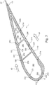
- FIG. 7 An exemplary embodiment of a turbine airfoil 1 is shown in figure 7 , as an embodiment of a turbo-engine component according to the present disclosure.
- the airfoil 1 comprises a leading edge 11 and a trailing edge12.
- a suction side and a pressure side are arranged between the leading edge and the trailing edge.
- a working fluid flow 50 flows around the airfoil, from the leading edge to the trailing edge, and along the pressure side and the section side.
- a trailing edge coolant slot 13 is provided at the trailing edge in a known manner.
- a wall 100 of the airfoil encloses coolant supply volumes 150 provided inside the airfoil, and being delimited by coolant side surfaces 120 of the wall 100.
- a hot gas side surface 110 of the wall is exposed to the working fluid flow 50.
- the wall 100 is equipped with a multitude of coolant discharge ducts (without reference numbers in this figure) which open out onto the hot gas side surface at coolant discharge openings 214.
- Each coolant discharge duct is in fluid communication with either a counterflow near wall cooling channel 220, or a parallel flow near wall cooling duct 221.
- Each near wall cooling duct is in fluid communication with a coolant supply volume 150 through a coolant inflow duct 230.
Landscapes
- Engineering & Computer Science (AREA)
- Mechanical Engineering (AREA)
- General Engineering & Computer Science (AREA)
- Turbine Rotor Nozzle Sealing (AREA)
Claims (12)
- Turbomaschinenbauteil (1), umfassend eine Wand (100), wobei die Wand (100) eine Heißgasseitenfläche (110) und eine Kühlmittelseitenfläche (120) umfasst, in der Wand (100) mindestens ein Kühlmittelauslasskanal (210) vorgesehen ist, der sich an einer Kühlmittelauslassöffnung (214) zu der Heißgasseitenfläche (110) öffnet, eine Kühlmittelströmungsrichtung vom Inneren des Kühlmittelauslasskanals (210) in Richtung der Auslassöffnung (214) begrenzt wird, der Kühlmittelauslasskanal (210) überdies durch eine innerhalb der Wand (100) vorgesehene Begrenzungsfläche begrenzt wird, der Kühlmittelauslasskanal (210) eine erste Querschnittsrichtung und eine zweite Querschnittsrichtung aufweist, der Kühlmittelauslasskanal (210) ein Blindhohlraum ist, der zu der Kühlmittelseitenfläche (120) hin geschlossen ist, und sich eine Abmessung des Kühlmittelauslasskanals (210), in der ersten Querschnittsrichtung gemessen, in Kühlmittelströmungsrichtung verringert;
wobei das Bauteil (1) zudem einen in der Wand (100) vorgesehenen und in Fluidverbindung mit dem Kühlmittelauslasskanal (210) stehenden Kühlmittelzuführungsweg umfasst, der sich an einer seitlichen Begrenzungsfläche des Kühlmittelauslasskanals (210) in einem Winkel ungleich null mit diesem verbindet; wobei der Kühlmittelzuführungsweg einen wandnahen Kühlkanal (220, 221) umfasst, der im Inneren der Wand (100) entlang einer Längsausdehnung der Wand (100) verläuft; wobei sich der wandnahe Kühlkanal (220, 221) von einem ersten Ende zu einem zweiten Ende erstreckt und das zweite Ende in Richtung des Kühlmittelauslasskanals (210) angeordnet ist; wobei das Bauteil dadurch gekennzeichnet ist, dass benachbart zu dem zweiten Ende des wandnahen Kühlkanals (220, 221) eine Strömungsbeschleunigungsvorrichtung (250) vorgesehen ist, welche die Fluidverbindung zwischen dem zweiten Ende und dem Kühlmittelauslasskanal (210) herstellt. - Turbomaschinenbauteil (1) nach dem vorstehenden Anspruch 1, dadurch gekennzeichnet, dass eine in der zweiten Querschnittsrichtung gemessene Abmessung des Kühlmittelauslasskanals in Kühlmittelströmungsrichtung zunimmt.
- Turbomaschinenbauteil (1) nach einem der vorstehenden Ansprüche, dadurch gekennzeichnet, dass sich ein durch den Kühlmittelauslasskanal (210) gebildeter Strömungsquerschnitt in Kühlmittelströmungsrichtung verringert.
- Turbomaschinenbauteil (1) nach einem der vorstehenden Ansprüche, dadurch gekennzeichnet, dass die Kühlmittelauslassöffnung (214) ein Spalt ist, wobei eine Längsausdehnung des Spalts entlang der zweiten Querschnittsrichtung verläuft.
- Turbomaschinenbauteil (1) nach einem der vorstehenden Ansprüche, dadurch gekennzeichnet, dass der Kühlmittelauslasskanal (210) in Bezug auf eine Senkrechte (111) der Heißgasseitenfläche in einem ersten Winkel (a) geneigt ist, wobei die Neigung in einer Ebene gebildet wird, die durch die erste Querschnittsrichtung und die Senkrechte (111) begrenzt wird, so dass die seitliche Begrenzungsfläche des Kühlmittelauslasskanals einen ersten Flächenabschnitt (211) umfasst, der in Richtung der Heißgasseitenfläche (110) der Wand (100) angeordnet ist, und einen zweiten Flächenabschnitt (212), der in Richtung der Kühlmittelseitenfläche (120) der Wand (100) angeordnet ist.
- Turbomaschinenbauteil (1) nach einem der vorstehenden Ansprüche, dadurch gekennzeichnet, dass der Kühlmittelauslasskanal (210) in Bezug auf eine Senkrechte (111) der Heißgasseitenfläche (110) in einem ersten Winkel (a) geneigt ist, wobei die Neigung, aus der Kühlmittelströmungsrichtung gesehen, in Bezug auf eine Hauptströmungsrichtung des Arbeitsfluids (50) des Bauteils (1) stromabwärts gerichtet ist.
- Turbomaschinenbauteil (1) nach einem der vorstehenden Ansprüche, dadurch gekennzeichnet, dass der Kühlmittelauslasskanal (210) durch eine Begrenzungsfläche begrenzt wird, die einen zu der Heißgasseitenfläche (110) hin gerichteten ersten Flächenabschnitt (211) und einen zu der Kühlmittelseitenfläche (120) hin gerichteten zweiten Flächenabschnitt (212) aufweist, wobei mindestens der erste (211) oder der zweite (212) Flächenabschnitt einen flachen Flächenabschnitt umfasst.
- Turbomaschinenbauteil (1) nach einem der vorstehenden Ansprüche, dadurch gekennzeichnet, das die Strömungsbeschleunigungsvorrichtung (250) einen freien Strahl (340) bewirkt, der von dem Kühlmittelzuführweg ausströmt.
- Turbomaschinenbauteil (1) nach einem der vorstehenden Ansprüche, dadurch gekennzeichnet, dass sich der Kühlmittelzuführweg durch eine Öffnung (251), die in einem seitlichen Begrenzungsflächenabschnitt (212) in Richtung der Kühlmittelseitenfläche (120) der Wand (100) vorgesehen ist, mit dem Kühlmittelauslasskanal (210) verbindet.
- Turbomaschinenbauteil (1) nach einem der vorstehenden Ansprüche, dadurch gekennzeichnet, dass ein Kühlmittelzuströmkanal (230) vorgesehen ist, der sich von der Kühlmittelseitenfläche (120) der Wand (100) zu dem wandnahen Kühlkanal (220, 221) erstreckt und an einer Seitenwand des wandnahen Kühlkanals (220, 221) mit diesem verbindet, wobei die Verbindungsstelle benachbart zu dem ersten Ende des wandnahen Kühlkanals (220, 221) auf einer Seite des wandnahen Kühlkanals (220, 221) angeordnet ist, die sich in Richtung der Kühlmittelseitenfläche (120) der Wand (100) befindet.
- Turbomaschinenbauteil (1) nach einem der vorstehenden Ansprüche, dadurch gekennzeichnet, dass mindestens zwei Kühlmittelauslasskanäle (210) vorgesehen sind, die jeweils eine Kühlmittelauslassöffnung (214) in Richtung der Heißgasseitenfläche (110) aufweisen, wobei jede der Kühlmittelauslassöffnungen (214) einen Querschnitt aufweist, der in einer ersten Richtung eine erste Ausdehnung aufweist, die kleiner ist als eine zweite Ausdehnung in einer zweiten Richtung, wobei die Kühlmitteauslassöffnungen (214) so angeordnet sind, dass kurze Kanten von zwei benachbarten Kühlmittelauslassöffnungen (214) nebeneinander angeordnet sind.
- Turbomaschinenbauteil (1) nach dem vorstehenden Anspruch, dadurch gekennzeichnet, dass die Kühlmittelauslassöffnungen (214) an ihren kurzen Kanten jeweils aneinander liegen, so dass sie eine gemeinsame Kühlmittelauslassöffnung (215) der mindestens zwei Kühlmittelauslasskanäle (210) bilden.
Priority Applications (5)
| Application Number | Priority Date | Filing Date | Title |
|---|---|---|---|
| EP15178849.4A EP3124745B1 (de) | 2015-07-29 | 2015-07-29 | Turbomaschinenkomponente mit filmgekühlter wand |
| KR1020160096602A KR20170015234A (ko) | 2015-07-29 | 2016-07-29 | 터보-엔진 부품 |
| JP2016150004A JP2017040256A (ja) | 2015-07-29 | 2016-07-29 | ターボエンジン構成部品 |
| CN201610610156.0A CN106437863B (zh) | 2015-07-29 | 2016-07-29 | 涡轮发动机部件 |
| US15/223,102 US10655474B2 (en) | 2015-07-29 | 2016-07-29 | Turbo-engine component having outer wall discharge openings |
Applications Claiming Priority (1)
| Application Number | Priority Date | Filing Date | Title |
|---|---|---|---|
| EP15178849.4A EP3124745B1 (de) | 2015-07-29 | 2015-07-29 | Turbomaschinenkomponente mit filmgekühlter wand |
Publications (2)
| Publication Number | Publication Date |
|---|---|
| EP3124745A1 EP3124745A1 (de) | 2017-02-01 |
| EP3124745B1 true EP3124745B1 (de) | 2018-03-28 |
Family
ID=53773283
Family Applications (1)
| Application Number | Title | Priority Date | Filing Date |
|---|---|---|---|
| EP15178849.4A Active EP3124745B1 (de) | 2015-07-29 | 2015-07-29 | Turbomaschinenkomponente mit filmgekühlter wand |
Country Status (5)
| Country | Link |
|---|---|
| US (1) | US10655474B2 (de) |
| EP (1) | EP3124745B1 (de) |
| JP (1) | JP2017040256A (de) |
| KR (1) | KR20170015234A (de) |
| CN (1) | CN106437863B (de) |
Cited By (1)
| Publication number | Priority date | Publication date | Assignee | Title |
|---|---|---|---|---|
| US11486259B1 (en) | 2021-11-05 | 2022-11-01 | General Electric Company | Component with cooling passage for a turbine engine |
Families Citing this family (15)
| Publication number | Priority date | Publication date | Assignee | Title |
|---|---|---|---|---|
| EP3124746B1 (de) * | 2015-07-29 | 2018-12-26 | Ansaldo Energia IP UK Limited | Verfahren zur kühlung einer turbomaschinenkomponente und turbomaschinenkomponente |
| US10533749B2 (en) * | 2015-10-27 | 2020-01-14 | Pratt & Whitney Cananda Corp. | Effusion cooling holes |
| US10871075B2 (en) | 2015-10-27 | 2020-12-22 | Pratt & Whitney Canada Corp. | Cooling passages in a turbine component |
| US10605093B2 (en) * | 2016-07-12 | 2020-03-31 | General Electric Company | Heat transfer device and related turbine airfoil |
| US20190218917A1 (en) * | 2018-01-17 | 2019-07-18 | General Electric Company | Engine component with set of cooling holes |
| US10724381B2 (en) * | 2018-03-06 | 2020-07-28 | Raytheon Technologies Corporation | Cooling passage with structural rib and film cooling slot |
| US11499433B2 (en) | 2018-12-18 | 2022-11-15 | General Electric Company | Turbine engine component and method of cooling |
| US11566527B2 (en) | 2018-12-18 | 2023-01-31 | General Electric Company | Turbine engine airfoil and method of cooling |
| US11352889B2 (en) | 2018-12-18 | 2022-06-07 | General Electric Company | Airfoil tip rail and method of cooling |
| US11174736B2 (en) | 2018-12-18 | 2021-11-16 | General Electric Company | Method of forming an additively manufactured component |
| US10767492B2 (en) | 2018-12-18 | 2020-09-08 | General Electric Company | Turbine engine airfoil |
| US10844728B2 (en) | 2019-04-17 | 2020-11-24 | General Electric Company | Turbine engine airfoil with a trailing edge |
| GB202105026D0 (en) | 2021-04-08 | 2021-05-26 | Siemens Energy Global Gmbh & Co Kg | Aerofoil and method |
| US11859511B2 (en) * | 2021-11-05 | 2024-01-02 | Rolls-Royce North American Technologies Inc. | Co and counter flow heat exchanger |
| KR102953259B1 (ko) | 2023-12-26 | 2026-04-17 | 두산에너빌리티 주식회사 | 에어포일 및 이를 포함하는 가스 터빈 |
Family Cites Families (20)
| Publication number | Priority date | Publication date | Assignee | Title |
|---|---|---|---|---|
| US4726735A (en) * | 1985-12-23 | 1988-02-23 | United Technologies Corporation | Film cooling slot with metered flow |
| US5405242A (en) * | 1990-07-09 | 1995-04-11 | United Technologies Corporation | Cooled vane |
| AT404160B (de) * | 1994-06-15 | 1998-09-25 | Inst Thermische Turbomaschinen | Hohle gasturbinenschaufel und verfahren zur aussen-film-kühlung derselben |
| GB9821639D0 (en) * | 1998-10-06 | 1998-11-25 | Rolls Royce Plc | Coolant passages for gas turbine components |
| DE10001109B4 (de) | 2000-01-13 | 2012-01-19 | Alstom Technology Ltd. | Gekühlte Schaufel für eine Gasturbine |
| GB2402715B (en) | 2003-06-10 | 2006-06-14 | Rolls Royce Plc | Gas turbine aerofoil |
| US7334992B2 (en) * | 2005-05-31 | 2008-02-26 | United Technologies Corporation | Turbine blade cooling system |
| US7766618B1 (en) | 2007-06-21 | 2010-08-03 | Florida Turbine Technologies, Inc. | Turbine vane endwall with cascading film cooling diffusion slots |
| US8594191B2 (en) | 2008-01-03 | 2013-11-26 | Broadcom Corporation | Video processing system and transcoder for use with layered video coding and methods for use therewith |
| US20100008759A1 (en) | 2008-07-10 | 2010-01-14 | General Electric Company | Methods and apparatuses for providing film cooling to turbine components |
| US8057182B2 (en) | 2008-11-21 | 2011-11-15 | General Electric Company | Metered cooling slots for turbine blades |
| US8591191B1 (en) * | 2010-11-22 | 2013-11-26 | Florida Turbine Technologies, Inc. | Film cooling hole for turbine airfoil |
| CH705185A1 (de) | 2011-06-29 | 2012-12-31 | Alstom Technology Ltd | Schaufel für eine Gasturbine sowie Verfahren zum Herstellen einer solchen Schaufel. |
| US8851848B1 (en) * | 2012-02-20 | 2014-10-07 | Florida Turbine Technologies, Inc. | Turbine blade with showerhead film cooling slots |
| US9296039B2 (en) | 2012-04-24 | 2016-03-29 | United Technologies Corporation | Gas turbine engine airfoil impingement cooling |
| US10100646B2 (en) * | 2012-08-03 | 2018-10-16 | United Technologies Corporation | Gas turbine engine component cooling circuit |
| CN103046967A (zh) | 2012-12-27 | 2013-04-17 | 中国燃气涡轮研究院 | 一种涡轮气冷叶片 |
| US9874110B2 (en) * | 2013-03-07 | 2018-01-23 | Rolls-Royce North American Technologies Inc. | Cooled gas turbine engine component |
| US10030525B2 (en) * | 2015-03-18 | 2018-07-24 | General Electric Company | Turbine engine component with diffuser holes |
| EP3124746B1 (de) * | 2015-07-29 | 2018-12-26 | Ansaldo Energia IP UK Limited | Verfahren zur kühlung einer turbomaschinenkomponente und turbomaschinenkomponente |
-
2015
- 2015-07-29 EP EP15178849.4A patent/EP3124745B1/de active Active
-
2016
- 2016-07-29 KR KR1020160096602A patent/KR20170015234A/ko not_active Withdrawn
- 2016-07-29 CN CN201610610156.0A patent/CN106437863B/zh active Active
- 2016-07-29 JP JP2016150004A patent/JP2017040256A/ja active Pending
- 2016-07-29 US US15/223,102 patent/US10655474B2/en active Active
Non-Patent Citations (1)
| Title |
|---|
| None * |
Cited By (1)
| Publication number | Priority date | Publication date | Assignee | Title |
|---|---|---|---|---|
| US11486259B1 (en) | 2021-11-05 | 2022-11-01 | General Electric Company | Component with cooling passage for a turbine engine |
Also Published As
| Publication number | Publication date |
|---|---|
| JP2017040256A (ja) | 2017-02-23 |
| CN106437863A (zh) | 2017-02-22 |
| CN106437863B (zh) | 2020-11-03 |
| EP3124745A1 (de) | 2017-02-01 |
| US20170030200A1 (en) | 2017-02-02 |
| KR20170015234A (ko) | 2017-02-08 |
| US10655474B2 (en) | 2020-05-19 |
Similar Documents
| Publication | Publication Date | Title |
|---|---|---|
| US10655474B2 (en) | Turbo-engine component having outer wall discharge openings | |
| EP3124746B1 (de) | Verfahren zur kühlung einer turbomaschinenkomponente und turbomaschinenkomponente | |
| EP0971095B1 (de) | Kühlbare Schaufel für Gasturbinen | |
| US8858176B1 (en) | Turbine airfoil with leading edge cooling | |
| US8714926B2 (en) | Turbine component cooling channel mesh with intersection chambers | |
| US8864469B1 (en) | Turbine rotor blade with super cooling | |
| US6607355B2 (en) | Turbine airfoil with enhanced heat transfer | |
| US8128366B2 (en) | Counter-vortex film cooling hole design | |
| US7997868B1 (en) | Film cooling hole for turbine airfoil | |
| US8246307B2 (en) | Blade for a rotor | |
| US9151173B2 (en) | Use of multi-faceted impingement openings for increasing heat transfer characteristics on gas turbine components | |
| JP5295540B2 (ja) | タービンシュラウドアセンブリの優先配分復熱式フィルム冷却を容易にするシステム | |
| CN101535602B (zh) | 涡轮叶片 | |
| US8764394B2 (en) | Component cooling channel | |
| US8613597B1 (en) | Turbine blade with trailing edge cooling | |
| EP2911815B1 (de) | Gusskern für eine kühlanordnung eines gasturbinenbauteils | |
| JP6407276B2 (ja) | 鋳造された山形配列によって強化された表面に角度づけられたインピンジメントを使用する後縁冷却を含むガスタービンエンジン構成部品 | |
| KR20060043297A (ko) | 터빈 에어 포일용 미세 회로 냉각 | |
| JP2004308658A (ja) | エーロフォイルの冷却方法とその装置 | |
| US20090126335A1 (en) | Cooling structure | |
| KR20050018594A (ko) | 터빈 블레이드용 마이크로회로 냉각 | |
| CA3020297C (en) | TURBINE SHIELD COOLING | |
| US7311498B2 (en) | Microcircuit cooling for blades | |
| US7967568B2 (en) | Gas turbine component with reduced cooling air requirement | |
| US8794906B1 (en) | Turbine stator vane with endwall cooling |
Legal Events
| Date | Code | Title | Description |
|---|---|---|---|
| PUAI | Public reference made under article 153(3) epc to a published international application that has entered the european phase |
Free format text: ORIGINAL CODE: 0009012 |
|
| AK | Designated contracting states |
Kind code of ref document: A1 Designated state(s): AL AT BE BG CH CY CZ DE DK EE ES FI FR GB GR HR HU IE IS IT LI LT LU LV MC MK MT NL NO PL PT RO RS SE SI SK SM TR |
|
| AX | Request for extension of the european patent |
Extension state: BA ME |
|
| RAP1 | Party data changed (applicant data changed or rights of an application transferred) |
Owner name: ANSALDO ENERGIA IP UK LIMITED |
|
| 17P | Request for examination filed |
Effective date: 20170801 |
|
| RBV | Designated contracting states (corrected) |
Designated state(s): AL AT BE BG CH CY CZ DE DK EE ES FI FR GB GR HR HU IE IS IT LI LT LU LV MC MK MT NL NO PL PT RO RS SE SI SK SM TR |
|
| RIC1 | Information provided on ipc code assigned before grant |
Ipc: F01D 5/18 20060101AFI20170831BHEP |
|
| GRAP | Despatch of communication of intention to grant a patent |
Free format text: ORIGINAL CODE: EPIDOSNIGR1 |
|
| INTG | Intention to grant announced |
Effective date: 20171018 |
|
| GRAS | Grant fee paid |
Free format text: ORIGINAL CODE: EPIDOSNIGR3 |
|
| GRAA | (expected) grant |
Free format text: ORIGINAL CODE: 0009210 |
|
| AK | Designated contracting states |
Kind code of ref document: B1 Designated state(s): AL AT BE BG CH CY CZ DE DK EE ES FI FR GB GR HR HU IE IS IT LI LT LU LV MC MK MT NL NO PL PT RO RS SE SI SK SM TR |
|
| REG | Reference to a national code |
Ref country code: GB Ref legal event code: FG4D |
|
| REG | Reference to a national code |
Ref country code: CH Ref legal event code: EP |
|
| REG | Reference to a national code |
Ref country code: AT Ref legal event code: REF Ref document number: 983639 Country of ref document: AT Kind code of ref document: T Effective date: 20180415 |
|
| REG | Reference to a national code |
Ref country code: IE Ref legal event code: FG4D |
|
| REG | Reference to a national code |
Ref country code: DE Ref legal event code: R096 Ref document number: 602015009253 Country of ref document: DE |
|
| PG25 | Lapsed in a contracting state [announced via postgrant information from national office to epo] |
Ref country code: LT Free format text: LAPSE BECAUSE OF FAILURE TO SUBMIT A TRANSLATION OF THE DESCRIPTION OR TO PAY THE FEE WITHIN THE PRESCRIBED TIME-LIMIT Effective date: 20180328 Ref country code: HR Free format text: LAPSE BECAUSE OF FAILURE TO SUBMIT A TRANSLATION OF THE DESCRIPTION OR TO PAY THE FEE WITHIN THE PRESCRIBED TIME-LIMIT Effective date: 20180328 Ref country code: NO Free format text: LAPSE BECAUSE OF FAILURE TO SUBMIT A TRANSLATION OF THE DESCRIPTION OR TO PAY THE FEE WITHIN THE PRESCRIBED TIME-LIMIT Effective date: 20180628 Ref country code: FI Free format text: LAPSE BECAUSE OF FAILURE TO SUBMIT A TRANSLATION OF THE DESCRIPTION OR TO PAY THE FEE WITHIN THE PRESCRIBED TIME-LIMIT Effective date: 20180328 |
|
| REG | Reference to a national code |
Ref country code: NL Ref legal event code: MP Effective date: 20180328 |
|
| REG | Reference to a national code |
Ref country code: LT Ref legal event code: MG4D |
|
| PG25 | Lapsed in a contracting state [announced via postgrant information from national office to epo] |
Ref country code: RS Free format text: LAPSE BECAUSE OF FAILURE TO SUBMIT A TRANSLATION OF THE DESCRIPTION OR TO PAY THE FEE WITHIN THE PRESCRIBED TIME-LIMIT Effective date: 20180328 Ref country code: SE Free format text: LAPSE BECAUSE OF FAILURE TO SUBMIT A TRANSLATION OF THE DESCRIPTION OR TO PAY THE FEE WITHIN THE PRESCRIBED TIME-LIMIT Effective date: 20180328 Ref country code: LV Free format text: LAPSE BECAUSE OF FAILURE TO SUBMIT A TRANSLATION OF THE DESCRIPTION OR TO PAY THE FEE WITHIN THE PRESCRIBED TIME-LIMIT Effective date: 20180328 Ref country code: GR Free format text: LAPSE BECAUSE OF FAILURE TO SUBMIT A TRANSLATION OF THE DESCRIPTION OR TO PAY THE FEE WITHIN THE PRESCRIBED TIME-LIMIT Effective date: 20180629 Ref country code: BG Free format text: LAPSE BECAUSE OF FAILURE TO SUBMIT A TRANSLATION OF THE DESCRIPTION OR TO PAY THE FEE WITHIN THE PRESCRIBED TIME-LIMIT Effective date: 20180628 |
|
| PG25 | Lapsed in a contracting state [announced via postgrant information from national office to epo] |
Ref country code: ES Free format text: LAPSE BECAUSE OF FAILURE TO SUBMIT A TRANSLATION OF THE DESCRIPTION OR TO PAY THE FEE WITHIN THE PRESCRIBED TIME-LIMIT Effective date: 20180328 Ref country code: PL Free format text: LAPSE BECAUSE OF FAILURE TO SUBMIT A TRANSLATION OF THE DESCRIPTION OR TO PAY THE FEE WITHIN THE PRESCRIBED TIME-LIMIT Effective date: 20180328 Ref country code: AL Free format text: LAPSE BECAUSE OF FAILURE TO SUBMIT A TRANSLATION OF THE DESCRIPTION OR TO PAY THE FEE WITHIN THE PRESCRIBED TIME-LIMIT Effective date: 20180328 Ref country code: NL Free format text: LAPSE BECAUSE OF FAILURE TO SUBMIT A TRANSLATION OF THE DESCRIPTION OR TO PAY THE FEE WITHIN THE PRESCRIBED TIME-LIMIT Effective date: 20180328 Ref country code: EE Free format text: LAPSE BECAUSE OF FAILURE TO SUBMIT A TRANSLATION OF THE DESCRIPTION OR TO PAY THE FEE WITHIN THE PRESCRIBED TIME-LIMIT Effective date: 20180328 Ref country code: RO Free format text: LAPSE BECAUSE OF FAILURE TO SUBMIT A TRANSLATION OF THE DESCRIPTION OR TO PAY THE FEE WITHIN THE PRESCRIBED TIME-LIMIT Effective date: 20180328 |
|
| PG25 | Lapsed in a contracting state [announced via postgrant information from national office to epo] |
Ref country code: SK Free format text: LAPSE BECAUSE OF FAILURE TO SUBMIT A TRANSLATION OF THE DESCRIPTION OR TO PAY THE FEE WITHIN THE PRESCRIBED TIME-LIMIT Effective date: 20180328 Ref country code: SM Free format text: LAPSE BECAUSE OF FAILURE TO SUBMIT A TRANSLATION OF THE DESCRIPTION OR TO PAY THE FEE WITHIN THE PRESCRIBED TIME-LIMIT Effective date: 20180328 Ref country code: CZ Free format text: LAPSE BECAUSE OF FAILURE TO SUBMIT A TRANSLATION OF THE DESCRIPTION OR TO PAY THE FEE WITHIN THE PRESCRIBED TIME-LIMIT Effective date: 20180328 |
|
| REG | Reference to a national code |
Ref country code: AT Ref legal event code: MK05 Ref document number: 983639 Country of ref document: AT Kind code of ref document: T Effective date: 20180328 |
|
| PG25 | Lapsed in a contracting state [announced via postgrant information from national office to epo] |
Ref country code: PT Free format text: LAPSE BECAUSE OF FAILURE TO SUBMIT A TRANSLATION OF THE DESCRIPTION OR TO PAY THE FEE WITHIN THE PRESCRIBED TIME-LIMIT Effective date: 20180730 |
|
| REG | Reference to a national code |
Ref country code: DE Ref legal event code: R097 Ref document number: 602015009253 Country of ref document: DE |
|
| PG25 | Lapsed in a contracting state [announced via postgrant information from national office to epo] |
Ref country code: AT Free format text: LAPSE BECAUSE OF FAILURE TO SUBMIT A TRANSLATION OF THE DESCRIPTION OR TO PAY THE FEE WITHIN THE PRESCRIBED TIME-LIMIT Effective date: 20180328 Ref country code: DK Free format text: LAPSE BECAUSE OF FAILURE TO SUBMIT A TRANSLATION OF THE DESCRIPTION OR TO PAY THE FEE WITHIN THE PRESCRIBED TIME-LIMIT Effective date: 20180328 |
|
| PLBE | No opposition filed within time limit |
Free format text: ORIGINAL CODE: 0009261 |
|
| STAA | Information on the status of an ep patent application or granted ep patent |
Free format text: STATUS: NO OPPOSITION FILED WITHIN TIME LIMIT |
|
| REG | Reference to a national code |
Ref country code: CH Ref legal event code: PL |
|
| 26N | No opposition filed |
Effective date: 20190103 |
|
| PG25 | Lapsed in a contracting state [announced via postgrant information from national office to epo] |
Ref country code: MC Free format text: LAPSE BECAUSE OF FAILURE TO SUBMIT A TRANSLATION OF THE DESCRIPTION OR TO PAY THE FEE WITHIN THE PRESCRIBED TIME-LIMIT Effective date: 20180328 Ref country code: LU Free format text: LAPSE BECAUSE OF NON-PAYMENT OF DUE FEES Effective date: 20180729 |
|
| REG | Reference to a national code |
Ref country code: BE Ref legal event code: MM Effective date: 20180731 |
|
| PG25 | Lapsed in a contracting state [announced via postgrant information from national office to epo] |
Ref country code: LI Free format text: LAPSE BECAUSE OF NON-PAYMENT OF DUE FEES Effective date: 20180731 Ref country code: CH Free format text: LAPSE BECAUSE OF NON-PAYMENT OF DUE FEES Effective date: 20180731 Ref country code: FR Free format text: LAPSE BECAUSE OF NON-PAYMENT OF DUE FEES Effective date: 20180731 |
|
| REG | Reference to a national code |
Ref country code: IE Ref legal event code: MM4A |
|
| PG25 | Lapsed in a contracting state [announced via postgrant information from national office to epo] |
Ref country code: BE Free format text: LAPSE BECAUSE OF NON-PAYMENT OF DUE FEES Effective date: 20180731 Ref country code: SI Free format text: LAPSE BECAUSE OF FAILURE TO SUBMIT A TRANSLATION OF THE DESCRIPTION OR TO PAY THE FEE WITHIN THE PRESCRIBED TIME-LIMIT Effective date: 20180328 |
|
| PG25 | Lapsed in a contracting state [announced via postgrant information from national office to epo] |
Ref country code: IE Free format text: LAPSE BECAUSE OF NON-PAYMENT OF DUE FEES Effective date: 20180729 |
|
| PG25 | Lapsed in a contracting state [announced via postgrant information from national office to epo] |
Ref country code: MT Free format text: LAPSE BECAUSE OF NON-PAYMENT OF DUE FEES Effective date: 20180729 |
|
| PG25 | Lapsed in a contracting state [announced via postgrant information from national office to epo] |
Ref country code: TR Free format text: LAPSE BECAUSE OF FAILURE TO SUBMIT A TRANSLATION OF THE DESCRIPTION OR TO PAY THE FEE WITHIN THE PRESCRIBED TIME-LIMIT Effective date: 20180328 |
|
| PG25 | Lapsed in a contracting state [announced via postgrant information from national office to epo] |
Ref country code: CY Free format text: LAPSE BECAUSE OF FAILURE TO SUBMIT A TRANSLATION OF THE DESCRIPTION OR TO PAY THE FEE WITHIN THE PRESCRIBED TIME-LIMIT Effective date: 20180328 Ref country code: HU Free format text: LAPSE BECAUSE OF FAILURE TO SUBMIT A TRANSLATION OF THE DESCRIPTION OR TO PAY THE FEE WITHIN THE PRESCRIBED TIME-LIMIT; INVALID AB INITIO Effective date: 20150729 Ref country code: MK Free format text: LAPSE BECAUSE OF NON-PAYMENT OF DUE FEES Effective date: 20180328 |
|
| PG25 | Lapsed in a contracting state [announced via postgrant information from national office to epo] |
Ref country code: IS Free format text: LAPSE BECAUSE OF FAILURE TO SUBMIT A TRANSLATION OF THE DESCRIPTION OR TO PAY THE FEE WITHIN THE PRESCRIBED TIME-LIMIT Effective date: 20180728 |
|
| P01 | Opt-out of the competence of the unified patent court (upc) registered |
Effective date: 20240430 |
|
| PGFP | Annual fee paid to national office [announced via postgrant information from national office to epo] |
Ref country code: DE Payment date: 20250722 Year of fee payment: 11 |
|
| PGFP | Annual fee paid to national office [announced via postgrant information from national office to epo] |
Ref country code: IT Payment date: 20250731 Year of fee payment: 11 |
|
| PGFP | Annual fee paid to national office [announced via postgrant information from national office to epo] |
Ref country code: GB Payment date: 20250724 Year of fee payment: 11 |