EP3124754A1 - Joint proche d'un trajet d'écoulement pour turbomachine - Google Patents
Joint proche d'un trajet d'écoulement pour turbomachine Download PDFInfo
- Publication number
- EP3124754A1 EP3124754A1 EP16179870.7A EP16179870A EP3124754A1 EP 3124754 A1 EP3124754 A1 EP 3124754A1 EP 16179870 A EP16179870 A EP 16179870A EP 3124754 A1 EP3124754 A1 EP 3124754A1
- Authority
- EP
- European Patent Office
- Prior art keywords
- flow path
- seal element
- element assembly
- seal
- near flow
- Prior art date
- Legal status (The legal status is an assumption and is not a legal conclusion. Google has not performed a legal analysis and makes no representation as to the accuracy of the status listed.)
- Withdrawn
Links
- 239000000463 material Substances 0.000 claims description 30
- 238000000034 method Methods 0.000 claims description 18
- 230000013011 mating Effects 0.000 claims description 17
- 229910045601 alloy Inorganic materials 0.000 claims description 9
- 239000000956 alloy Substances 0.000 claims description 9
- 239000011153 ceramic matrix composite Substances 0.000 claims description 8
- 238000003754 machining Methods 0.000 claims description 7
- 239000011248 coating agent Substances 0.000 claims description 6
- 238000000576 coating method Methods 0.000 claims description 6
- 229910001011 CMSX-4 Inorganic materials 0.000 claims description 5
- 238000005553 drilling Methods 0.000 claims description 5
- 238000000227 grinding Methods 0.000 claims description 5
- 238000000465 moulding Methods 0.000 claims description 5
- 239000002245 particle Substances 0.000 claims description 5
- 229920002134 Carboxymethyl cellulose Polymers 0.000 claims description 4
- 235000010948 carboxy methyl cellulose Nutrition 0.000 claims description 4
- 229920006184 cellulose methylcellulose Polymers 0.000 claims description 4
- 238000012710 chemistry, manufacturing and control Methods 0.000 claims description 4
- 229910001220 stainless steel Inorganic materials 0.000 claims description 4
- 229910000601 superalloy Inorganic materials 0.000 claims description 3
- 229910000531 Co alloy Inorganic materials 0.000 claims description 2
- 239000007789 gas Substances 0.000 description 10
- HBMJWWWQQXIZIP-UHFFFAOYSA-N silicon carbide Chemical compound [Si+]#[C-] HBMJWWWQQXIZIP-UHFFFAOYSA-N 0.000 description 6
- PNEYBMLMFCGWSK-UHFFFAOYSA-N aluminium oxide Inorganic materials [O-2].[O-2].[O-2].[Al+3].[Al+3] PNEYBMLMFCGWSK-UHFFFAOYSA-N 0.000 description 4
- 239000000835 fiber Substances 0.000 description 4
- 229910010271 silicon carbide Inorganic materials 0.000 description 4
- 229910052582 BN Inorganic materials 0.000 description 2
- PZNSFCLAULLKQX-UHFFFAOYSA-N Boron nitride Chemical compound N#B PZNSFCLAULLKQX-UHFFFAOYSA-N 0.000 description 2
- 229910000990 Ni alloy Inorganic materials 0.000 description 2
- 238000002485 combustion reaction Methods 0.000 description 2
- 239000002131 composite material Substances 0.000 description 2
- 239000011224 oxide ceramic Substances 0.000 description 2
- 229910052574 oxide ceramic Inorganic materials 0.000 description 2
- 230000007704 transition Effects 0.000 description 2
- 238000011144 upstream manufacturing Methods 0.000 description 2
- 230000002411 adverse Effects 0.000 description 1
- 238000001816 cooling Methods 0.000 description 1
- 238000010586 diagram Methods 0.000 description 1
- 238000004519 manufacturing process Methods 0.000 description 1
- 238000012986 modification Methods 0.000 description 1
- 230000004048 modification Effects 0.000 description 1
- 230000002028 premature Effects 0.000 description 1
- 230000001902 propagating effect Effects 0.000 description 1
- 239000000126 substance Substances 0.000 description 1
Images


Classifications
-
- F—MECHANICAL ENGINEERING; LIGHTING; HEATING; WEAPONS; BLASTING
- F01—MACHINES OR ENGINES IN GENERAL; ENGINE PLANTS IN GENERAL; STEAM ENGINES
- F01D—NON-POSITIVE DISPLACEMENT MACHINES OR ENGINES, e.g. STEAM TURBINES
- F01D11/00—Preventing or minimising internal leakage of working-fluid, e.g. between stages
- F01D11/08—Preventing or minimising internal leakage of working-fluid, e.g. between stages for sealing space between rotor blade tips and stator
-
- F—MECHANICAL ENGINEERING; LIGHTING; HEATING; WEAPONS; BLASTING
- F01—MACHINES OR ENGINES IN GENERAL; ENGINE PLANTS IN GENERAL; STEAM ENGINES
- F01D—NON-POSITIVE DISPLACEMENT MACHINES OR ENGINES, e.g. STEAM TURBINES
- F01D11/00—Preventing or minimising internal leakage of working-fluid, e.g. between stages
- F01D11/001—Preventing or minimising internal leakage of working-fluid, e.g. between stages for sealing space between stator blade and rotor
-
- F—MECHANICAL ENGINEERING; LIGHTING; HEATING; WEAPONS; BLASTING
- F16—ENGINEERING ELEMENTS AND UNITS; GENERAL MEASURES FOR PRODUCING AND MAINTAINING EFFECTIVE FUNCTIONING OF MACHINES OR INSTALLATIONS; THERMAL INSULATION IN GENERAL
- F16J—PISTONS; CYLINDERS; SEALINGS
- F16J15/00—Sealings
- F16J15/16—Sealings between relatively-moving surfaces
- F16J15/34—Sealings between relatively-moving surfaces with slip-ring pressed against a more or less radial face on one member
- F16J15/3436—Pressing means
- F16J15/3456—Pressing means without external means for pressing the ring against the face, e.g. slip-ring with a resilient lip
-
- F—MECHANICAL ENGINEERING; LIGHTING; HEATING; WEAPONS; BLASTING
- F05—INDEXING SCHEMES RELATING TO ENGINES OR PUMPS IN VARIOUS SUBCLASSES OF CLASSES F01-F04
- F05D—INDEXING SCHEME FOR ASPECTS RELATING TO NON-POSITIVE-DISPLACEMENT MACHINES OR ENGINES, GAS-TURBINES OR JET-PROPULSION PLANTS
- F05D2220/00—Application
- F05D2220/30—Application in turbines
-
- F—MECHANICAL ENGINEERING; LIGHTING; HEATING; WEAPONS; BLASTING
- F05—INDEXING SCHEMES RELATING TO ENGINES OR PUMPS IN VARIOUS SUBCLASSES OF CLASSES F01-F04
- F05D—INDEXING SCHEME FOR ASPECTS RELATING TO NON-POSITIVE-DISPLACEMENT MACHINES OR ENGINES, GAS-TURBINES OR JET-PROPULSION PLANTS
- F05D2230/00—Manufacture
- F05D2230/10—Manufacture by removing material
-
- F—MECHANICAL ENGINEERING; LIGHTING; HEATING; WEAPONS; BLASTING
- F05—INDEXING SCHEMES RELATING TO ENGINES OR PUMPS IN VARIOUS SUBCLASSES OF CLASSES F01-F04
- F05D—INDEXING SCHEME FOR ASPECTS RELATING TO NON-POSITIVE-DISPLACEMENT MACHINES OR ENGINES, GAS-TURBINES OR JET-PROPULSION PLANTS
- F05D2230/00—Manufacture
- F05D2230/80—Repairing, retrofitting or upgrading methods
-
- F—MECHANICAL ENGINEERING; LIGHTING; HEATING; WEAPONS; BLASTING
- F05—INDEXING SCHEMES RELATING TO ENGINES OR PUMPS IN VARIOUS SUBCLASSES OF CLASSES F01-F04
- F05D—INDEXING SCHEME FOR ASPECTS RELATING TO NON-POSITIVE-DISPLACEMENT MACHINES OR ENGINES, GAS-TURBINES OR JET-PROPULSION PLANTS
- F05D2240/00—Components
- F05D2240/20—Rotors
- F05D2240/30—Characteristics of rotor blades, i.e. of any element transforming dynamic fluid energy to or from rotational energy and being attached to a rotor
- F05D2240/307—Characteristics of rotor blades, i.e. of any element transforming dynamic fluid energy to or from rotational energy and being attached to a rotor related to the tip of a rotor blade
-
- F—MECHANICAL ENGINEERING; LIGHTING; HEATING; WEAPONS; BLASTING
- F05—INDEXING SCHEMES RELATING TO ENGINES OR PUMPS IN VARIOUS SUBCLASSES OF CLASSES F01-F04
- F05D—INDEXING SCHEME FOR ASPECTS RELATING TO NON-POSITIVE-DISPLACEMENT MACHINES OR ENGINES, GAS-TURBINES OR JET-PROPULSION PLANTS
- F05D2300/00—Materials; Properties thereof
- F05D2300/10—Metals, alloys or intermetallic compounds
- F05D2300/17—Alloys
- F05D2300/171—Steel alloys
-
- F—MECHANICAL ENGINEERING; LIGHTING; HEATING; WEAPONS; BLASTING
- F05—INDEXING SCHEMES RELATING TO ENGINES OR PUMPS IN VARIOUS SUBCLASSES OF CLASSES F01-F04
- F05D—INDEXING SCHEME FOR ASPECTS RELATING TO NON-POSITIVE-DISPLACEMENT MACHINES OR ENGINES, GAS-TURBINES OR JET-PROPULSION PLANTS
- F05D2300/00—Materials; Properties thereof
- F05D2300/10—Metals, alloys or intermetallic compounds
- F05D2300/17—Alloys
- F05D2300/175—Superalloys
-
- F—MECHANICAL ENGINEERING; LIGHTING; HEATING; WEAPONS; BLASTING
- F05—INDEXING SCHEMES RELATING TO ENGINES OR PUMPS IN VARIOUS SUBCLASSES OF CLASSES F01-F04
- F05D—INDEXING SCHEME FOR ASPECTS RELATING TO NON-POSITIVE-DISPLACEMENT MACHINES OR ENGINES, GAS-TURBINES OR JET-PROPULSION PLANTS
- F05D2300/00—Materials; Properties thereof
- F05D2300/60—Properties or characteristics given to material by treatment or manufacturing
- F05D2300/603—Composites; e.g. fibre-reinforced
- F05D2300/6033—Ceramic matrix composites [CMC]
-
- Y—GENERAL TAGGING OF NEW TECHNOLOGICAL DEVELOPMENTS; GENERAL TAGGING OF CROSS-SECTIONAL TECHNOLOGIES SPANNING OVER SEVERAL SECTIONS OF THE IPC; TECHNICAL SUBJECTS COVERED BY FORMER USPC CROSS-REFERENCE ART COLLECTIONS [XRACs] AND DIGESTS
- Y02—TECHNOLOGIES OR APPLICATIONS FOR MITIGATION OR ADAPTATION AGAINST CLIMATE CHANGE
- Y02T—CLIMATE CHANGE MITIGATION TECHNOLOGIES RELATED TO TRANSPORTATION
- Y02T50/00—Aeronautics or air transport
- Y02T50/60—Efficient propulsion technologies, e.g. for aircraft
Definitions
- the present invention relates generally to the art of turbomachines, and, more specifically, to a near flow path seal for a turbomachine and method of repairing the near flow path seal.
- Turbomachines include a casing that houses a turbine.
- the turbine includes a plurality of blades or buckets that extend along a gas path.
- the buckets are supported by a number of turbine rotors that define a plurality of turbine stages.
- a combustor assembly generates hot gases that are passed through a transition piece toward the plurality of turbine stages.
- gases at a lower temperature flow from a compressor toward a wheelspace of the turbine.
- the lower temperature gases provide cooling for the rotors as well as other internal components of the turbine.
- the turbine includes near flow path seals that are arranged between adjacent rotors. The near flow path seals are configured to fit closely adjacent the rotors or buckets to reduce leakage from the gas path into the wheelspace.
- Near flow path seals typically include seal elements, also referred to as teeth, that are in rotational contact with a stator positioned between adjacent buckets.
- the stator includes a honeycomb region typically composed of a nickel alloy, which is in rotational contact with seal elements of the near flow path seals, which are also typically composed of a nickel alloy.
- the chemical affinity between seal elements and honeycomb enables galling to take place and results in cracks propagating from tips of the seal elements in premature failures.
- the present invention is directed to a near flow path seal member for a turbomachine including a seal body having a first end portion extending to a second end portion having a dovetail member.
- the first end portion includes a third end and a fourth end having a surface extending therebetween and facing away from the dovetail member.
- the surface having a longitudinal axis extends between the third end and the fourth end.
- a recess formed in the surface has a geometry to receive a seal element assembly having a base extending to at least one seal element. The seal element assembly is selectively installable or removable from the recess.
- the present invention is also directed to a method of repairing a near flow path seal member in an installed position of a turbomachine, including providing a seal body having a first end portion extending to a second end portion having a dovetail member.
- the first end portion includes a third end and a fourth end defining a surface extending therebetween and facing away from the dovetail member.
- the surface has a longitudinal axis extending between the third end and the fourth end.
- a recess formed in the surface has a geometry to receive a seal element assembly having a base extending to at least one seal element.
- the seal element assembly has been previously installed.
- the method further includes removing the seal element assembly and installing another seal element assembly.
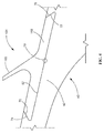
- Turbomachine 2 includes a compressor portion 4 operatively connected to a turbine portion 6.
- a combustor assembly 8 is fluidly connected to compressor portion 4 and turbine portion 6.
- Combustor assembly 8 is formed from a plurality of circumferentially spaced combustors, one of which is indicated at 10. Of course, it should be understood that combustor assembly 8 could include other arrangements of combustors.
- Compressor portion 4 is also linked to turbine portion 6 through a common compressor/turbine shaft 12.
- Combustor assembly 8 delivers products of combustion through a transition piece (not shown) to a gas path 18 in turbine portion 6. The products of combustion expand through turbine portion 6, for example, power a generator, to a pump, an aircraft or the like.
- turbine portion 6 includes a number of stages, one of which is shown at 20.
- Stage 20 includes a plurality of stators or nozzles, one of which is indicated at 24, and a plurality of buckets or blades, one of which is indicated at 26, mounted to a rotor wheel (not shown).
- another plurality of blades or buckets, one of which is indicated at 28 is arranged upstream of nozzle 24.
- Buckets 28 form part of an upstream stage in turbine portion 6.
- Turbomachine 2 is also shown to include a plurality of near flow path seal members, one of which is indicated at 30 arranged between buckets 26 and 28 and below nozzle 24.
- Near flow path seal members 30 are mounted to shaft 12 through a seal member rotor 32. Near flow path seal members 30 are configured to prevent an exchange of gases between gas path 18 and a wheelspace 34 of turbomachine 2. At this point it should be understood that turbomachine 2 includes additional near flow path seal members (not shown) arranged between adjacent stages (also not shown) of turbine portion 6.
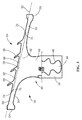
- Near flow path seal member 30 includes a body or seal body 40, including a first end portion 42 that extends to a second end portion 44 through a neck or intermediate portion 46. Second end portion 44 includes a dove tail member 48. Dove tail member 48 provides an interface between near flow path seal member 30 and seal member rotor 32.
- FIG. 3 shows first end portion 42 of near flow path seal member 30 includes a first arm member 50 and an opposed second arm member 52 that are each cantilevered from first end portion 42 of seal body 40.
- First arm member 50 extends to a third end 54 and second arm member 52 extends to a trailing or fourth end 56.
- First end portion 42 has a surface 58 extending between third end 54 and fourth end 56 and facing away from dove tail member 48.
- Surface 58 has a longitudinal axis 60 extending between third end 54 and fourth end 56.
- a recess 62 is formed in surface 58 having a geometry to receive a seal element assembly 64 having a base 66 extending to at least one seal element 68.
- seal element assembly 64 is selectively installable or removable from recess 62.
- Seal element 68 may have a thickness of between about 0.07 inch and about 2.50 inch, between about 0.07 inch and about 1.5 inch, between about 0.1 inch and about 0.75 inch, between about 0.1 inch and about 0.50 inch, about 0.1 inch, or any suitable range or sub-range thereof.
- seal element assembly 64 can be manufactured by a machining process, such as with lathes, mills, routers, grinders or other suitable machining process, reducing the cost associated with manufacturing a near flow path seal member.
- seal element assembly 64 and seal body 40 may be composed of different materials.
- seal element assembly 64 is composed of the group consisting of cobalt-base alloys, such as L-605, HS-188, FSX-414, nickel-base alloys such as R108, GTD-262, GTD-141+, GTD-141, GTD-111, Rene N2, IN-718, IN-725, IN-706, IN-901, IN-925, Hast-X, IN-625, stainless steels, such as 3XX series and 4XX series may be utilized depending on the ambient temperature in the turbine, ceramic matrix composites ("CMCs"), such as SiC fiber reinforced SiC composites and Alumina fiber reinforced oxide ceramic composites, coating materials overlying the seal element assembly, such as CM-64, Stellite-6, T-800, alumina, silicon carbide, boron nitride and capable of preventing galling when placed in contact with the seal body, or combinations thereof.
- CMCs ceramic matrix composites
- seal body 40 is composed of the group consisting of superalloys, including cobalt-base alloys, such as L-605, HS-188, FSX-414, nickel-base alloys such as R108, GTD-262, GTD-141+, GTD-141, GTD-111, Rene N2, IN-718, IN-725, IN-706, IN-901, IN-925, Hast-X, IN-625, stainless steels, such as 3XX series and 4XX series may be utilized depending on the ambient temperature in the turbine, ceramic matrix composites (“CMCs”), such as SiC fiber reinforced SiC composites and Alumina fiber reinforced oxide ceramic composites, coating materials, such as Stellite-6, LOB1800G, Alumazite, Alumina, Silicon Carbide and Boron Nitride overlying recess 62 and capable of preventing galling and fretting when placed in contact with base 66 of seal element assembly 64, or combinations thereof.
- cobalt-base alloys such as L-605, HS-188,
- seal element assembly 64 material selection can be increased to include non-weld-repairable alloys, such as Rene'-108 (MAR M-247 or CM-247), Rene'-142, Rene'-N2, Rene'-N6, Rene'-195, GTD-444, GTD-111, PWA-1480, CMSX-4 that may have greater than about 30 percent by volume of gamma prime particles in their microstructure.
- non-weld-repairable alloys such as Rene'-108 (MAR M-247 or CM-247), Rene'-142, Rene'-N2, Rene'-N6, Rene'-195, GTD-444, GTD-111, PWA-1480, CMSX-4 that may have greater than about 30 percent by volume of gamma prime particles in their microstructure.
- the geometry of recess 62 is a slot having opposed ends 70, 72 having mating features permitting a slidable engagement/disengagement with base 66 of seal element assembly 64.
- ends 70, 72 of recess 62 define mating features such as ends 70, 72 being inwardly directed toward each other to permit slidable engagement with corresponding ends 74, 76 of base 66 of seal element assembly 64.
- recess 62 defines mating features such as ends 70, 72 being serrated to permit slidable engagement with corresponding ends 74, 76 of base 66 of seal element assembly 64.
- a direction of slidable engagement/disengagement is substantially normal to longitudinal axis 60.
- sealing features is intended to include any portion along surface 58 of first end portion 42 in contact with base 66 of seal element assembly 64.
- slidable engagement includes deforming a portion of the mating features, as indicated by deformed region 78, in at least one of recess 62 and base 66 of seal element assembly 64 subsequent to installing seal element assembly 64.
- slidable disengagement includes removal of deformed portion 78 of the mating features formed in at least one of recess 62 and base 66 of seal element assembly 64 subsequent to disengaging seal element assembly 64 and base 66 of seal element assembly 64 subsequent to disengaging seal element assembly 64.
- removal of deformed portion 78 is achieved by drilling, grinding or other suitable operation usable to remove material from one or more of seal element assembly 64 and seal body 40.
- FIG. 4 shows an exemplary embodiment of seal element assembly 164 having a base 166 and one seal element 168, similar to seal element assembly 64.
- FIG. 5 shows the exemplary embodiment of seal element assembly 264 having a base 266 and a pair of seal elements 268, similar to seal element assembly 64.
- FIG. 5 shows the exemplary embodiment of seal element assembly 364 having a base 366 and a pair of seal elements 368, similar to seal element assembly 64. It is to be understood, such as shown in FIG. 5 , that more than one seal element assembly (e.g., 264 and 364) may be used with nearflow path seal members.
- more than one seal element assembly e.g., 264 and 364 may be used with nearflow path seal members.
- seal element assembly may include one or more seal elements.
- FIG. 6 is a flow chart that illustrates a method of repairing a near flow path seal member in an installed position of a turbomachine, although other methods may be used.
- the initial step 100 of the process typically includes removing seal element assembly 64 ( FIG. 3 ).
- Step 100 of removing seal element assembly 64 includes removing deformed portion 78 from mating surfaces formed in at least one of recess 62 ( FIG. 3 ) and base 66 of seal element assembly 64 ( FIG. 3 ), such as by drilling, grinding or other suitable material removal process.
- Step 100 further includes removing seal element assembly 64 ( FIG.
- seal element assembly 64 is manufactured by a machining process, such as with lathes, mills, routers, grinders or other suitable machining process.
- Step 102 of installing another seal element 64 includes application of sufficient force to seal element assembly 64 to slidably move seat element assembly 64 relative to recess 62 until seal element assembly 64 has been installed in near flow path seal member 30 in turbomachine 2.
- Step 102 further includes deforming a portion of the mating features, as indicated by deformed region 78 ( FIG. 3 ), in at least one of recess 62 and base 66 of seal element assembly 64 subsequent to installing seal element assembly 64.
Landscapes
- Engineering & Computer Science (AREA)
- General Engineering & Computer Science (AREA)
- Mechanical Engineering (AREA)
- Turbine Rotor Nozzle Sealing (AREA)
- Sealing Using Fluids, Sealing Without Contact, And Removal Of Oil (AREA)
Applications Claiming Priority (1)
| Application Number | Priority Date | Filing Date | Title |
|---|---|---|---|
| US14/812,568 US20170030212A1 (en) | 2015-07-29 | 2015-07-29 | Near flow path seal for a turbomachine |
Publications (1)
| Publication Number | Publication Date |
|---|---|
| EP3124754A1 true EP3124754A1 (fr) | 2017-02-01 |
Family
ID=56842587
Family Applications (1)
| Application Number | Title | Priority Date | Filing Date |
|---|---|---|---|
| EP16179870.7A Withdrawn EP3124754A1 (fr) | 2015-07-29 | 2016-07-18 | Joint proche d'un trajet d'écoulement pour turbomachine |
Country Status (4)
| Country | Link |
|---|---|
| US (1) | US20170030212A1 (fr) |
| EP (1) | EP3124754A1 (fr) |
| JP (1) | JP2017031972A (fr) |
| CN (1) | CN106401656A (fr) |
Families Citing this family (4)
| Publication number | Priority date | Publication date | Assignee | Title |
|---|---|---|---|---|
| US11208907B2 (en) * | 2017-07-13 | 2021-12-28 | Raytheon Technologies Corporation | Seals and methods of making seals |
| US10941672B2 (en) | 2018-09-14 | 2021-03-09 | DOOSAN Heavy Industries Construction Co., LTD | Stationary vane nozzle of gas turbine |
| US11339675B2 (en) * | 2019-09-13 | 2022-05-24 | Raytheon Technologies Corporation | Seal seat insert for gas turbine engines |
| FR3120894B1 (fr) * | 2021-03-19 | 2023-02-24 | Safran Aircraft Engines | Rotor de turbomachine, comprenant un anneau de joint a labyrinthe monte sur des viroles de disque |
Citations (6)
| Publication number | Priority date | Publication date | Assignee | Title |
|---|---|---|---|---|
| US3846899A (en) * | 1972-07-28 | 1974-11-12 | Gen Electric | A method of constructing a labyrinth seal |
| US20120301275A1 (en) * | 2011-05-26 | 2012-11-29 | Suciu Gabriel L | Integrated ceramic matrix composite rotor module for a gas turbine engine |
| US20130189087A1 (en) * | 2012-01-20 | 2013-07-25 | General Electric Company | Near flow path seal for a turbomachine |
| EP2657456A2 (fr) * | 2012-04-27 | 2013-10-30 | General Electric Company | Dispositif d'étanchéité inter-arbres séparable pour moteur de turbine à gaz |
| WO2015023860A1 (fr) * | 2013-08-15 | 2015-02-19 | United Technologies Corporation | Réduction de contrainte par poche d'enrobage pour disque rotor d'un moteur à turbine à gaz |
| EP2915955A1 (fr) * | 2014-03-04 | 2015-09-09 | Rolls-Royce North American Technologies, Inc. | Joint d'étanchéité de la extrémité d'une aube pour une turbine à gaz |
Family Cites Families (5)
| Publication number | Priority date | Publication date | Assignee | Title |
|---|---|---|---|---|
| US5080556A (en) * | 1990-09-28 | 1992-01-14 | General Electric Company | Thermal seal for a gas turbine spacer disc |
| US9039358B2 (en) * | 2007-01-03 | 2015-05-26 | United Technologies Corporation | Replaceable blade outer air seal design |
| US20130186103A1 (en) * | 2012-01-20 | 2013-07-25 | General Electric Company | Near flow path seal for a turbomachine |
| US9546554B2 (en) * | 2012-09-27 | 2017-01-17 | Honeywell International Inc. | Gas turbine engine components with blade tip cooling |
| US9605552B2 (en) * | 2013-06-10 | 2017-03-28 | General Electric Company | Non-integral segmented angel-wing seal |
-
2015
- 2015-07-29 US US14/812,568 patent/US20170030212A1/en not_active Abandoned
-
2016
- 2016-07-14 JP JP2016139003A patent/JP2017031972A/ja active Pending
- 2016-07-18 EP EP16179870.7A patent/EP3124754A1/fr not_active Withdrawn
- 2016-07-29 CN CN201610609649.2A patent/CN106401656A/zh active Pending
Patent Citations (6)
| Publication number | Priority date | Publication date | Assignee | Title |
|---|---|---|---|---|
| US3846899A (en) * | 1972-07-28 | 1974-11-12 | Gen Electric | A method of constructing a labyrinth seal |
| US20120301275A1 (en) * | 2011-05-26 | 2012-11-29 | Suciu Gabriel L | Integrated ceramic matrix composite rotor module for a gas turbine engine |
| US20130189087A1 (en) * | 2012-01-20 | 2013-07-25 | General Electric Company | Near flow path seal for a turbomachine |
| EP2657456A2 (fr) * | 2012-04-27 | 2013-10-30 | General Electric Company | Dispositif d'étanchéité inter-arbres séparable pour moteur de turbine à gaz |
| WO2015023860A1 (fr) * | 2013-08-15 | 2015-02-19 | United Technologies Corporation | Réduction de contrainte par poche d'enrobage pour disque rotor d'un moteur à turbine à gaz |
| EP2915955A1 (fr) * | 2014-03-04 | 2015-09-09 | Rolls-Royce North American Technologies, Inc. | Joint d'étanchéité de la extrémité d'une aube pour une turbine à gaz |
Also Published As
| Publication number | Publication date |
|---|---|
| CN106401656A (zh) | 2017-02-15 |
| JP2017031972A (ja) | 2017-02-09 |
| US20170030212A1 (en) | 2017-02-02 |
Similar Documents
| Publication | Publication Date | Title |
|---|---|---|
| US10267156B2 (en) | Turbine bucket assembly and turbine system | |
| EP1657405B1 (fr) | Assemblage d'aubes directrices de turbine à gaz | |
| EP2626169A2 (fr) | Procédés et ensembles d'outillages pour la fabrication de composants de moteur de turbine à gaz métallurgiquement consolidés | |
| EP2000631A2 (fr) | Rotor aubagé et procédé de fabrication associé | |
| EP3196322A1 (fr) | Joint mince pour une turbine à gaz | |
| GB2482247A (en) | Metallic sheath | |
| US20150345307A1 (en) | Turbine bucket assembly and turbine system | |
| EP2196631A2 (fr) | Composant doté d'une couche abrasive et procédé d'application d'une couche abrasive sur un composant | |
| EP3877629A1 (fr) | Fixation d'extrémité d'aube de turbomachine | |
| US10047611B2 (en) | Turbine blade attachment curved rib stiffeners | |
| US20150345309A1 (en) | Turbine bucket assembly and turbine system | |
| EP3124754A1 (fr) | Joint proche d'un trajet d'écoulement pour turbomachine | |
| US20150345314A1 (en) | Turbine bucket assembly and turbine system | |
| EP2855898B1 (fr) | Bague tampon d'aube de stator | |
| US20180156046A1 (en) | Rotor blade for a gas turbine | |
| US9045984B2 (en) | Stator vane mistake proofing | |
| EP2434099A2 (fr) | Aube pour moteur à turbine à gaz | |
| US11401834B2 (en) | Method of securing a ceramic matrix composite (CMC) component to a metallic substructure using CMC straps | |
| US20170218775A1 (en) | Turbine blade attachment rails for attachment fillet stress reduction | |
| US20150345310A1 (en) | Turbine bucket assembly and turbine system | |
| US11480061B2 (en) | Method for replacing metal airfoil with ceramic airfoil, and related turbomachine blade | |
| US20210131291A1 (en) | Turbine blade with tip shroud cooling passage | |
| EP4553282A1 (fr) | Moteur à turbine ayant une aube avec des trous de refroidissement | |
| EP4553284A1 (fr) | Turbomachine avec un ensemble d'aubes ayant des trous de refroidissement | |
| EP4553280A1 (fr) | Turbomachine avec un ensemble d'aubes ayant des conduits de refroidissement |
Legal Events
| Date | Code | Title | Description |
|---|---|---|---|
| PUAI | Public reference made under article 153(3) epc to a published international application that has entered the european phase |
Free format text: ORIGINAL CODE: 0009012 |
|
| AK | Designated contracting states |
Kind code of ref document: A1 Designated state(s): AL AT BE BG CH CY CZ DE DK EE ES FI FR GB GR HR HU IE IS IT LI LT LU LV MC MK MT NL NO PL PT RO RS SE SI SK SM TR |
|
| AX | Request for extension of the european patent |
Extension state: BA ME |
|
| 17P | Request for examination filed |
Effective date: 20170801 |
|
| RBV | Designated contracting states (corrected) |
Designated state(s): AL AT BE BG CH CY CZ DE DK EE ES FI FR GB GR HR HU IE IS IT LI LT LU LV MC MK MT NL NO PL PT RO RS SE SI SK SM TR |
|
| STAA | Information on the status of an ep patent application or granted ep patent |
Free format text: STATUS: THE APPLICATION IS DEEMED TO BE WITHDRAWN |
|
| 18D | Application deemed to be withdrawn |
Effective date: 20200201 |