EP3124773A1 - Motorsteuerungsvorrichtung für fahrzeug und motorsteuerungsverfahren für fahrzeug - Google Patents
Motorsteuerungsvorrichtung für fahrzeug und motorsteuerungsverfahren für fahrzeug Download PDFInfo
- Publication number
- EP3124773A1 EP3124773A1 EP15769015.7A EP15769015A EP3124773A1 EP 3124773 A1 EP3124773 A1 EP 3124773A1 EP 15769015 A EP15769015 A EP 15769015A EP 3124773 A1 EP3124773 A1 EP 3124773A1
- Authority
- EP
- European Patent Office
- Prior art keywords
- torque
- command
- engine
- phase
- value
- Prior art date
- Legal status (The legal status is an assumption and is not a legal conclusion. Google has not performed a legal analysis and makes no representation as to the accuracy of the status listed.)
- Withdrawn
Links
- 238000000034 method Methods 0.000 title claims description 126
- 230000005540 biological transmission Effects 0.000 claims abstract description 201
- 230000007246 mechanism Effects 0.000 claims abstract description 160
- 230000007423 decrease Effects 0.000 claims description 74
- 230000008859 change Effects 0.000 claims description 61
- 230000007704 transition Effects 0.000 claims description 6
- 230000008569 process Effects 0.000 description 117
- 230000001133 acceleration Effects 0.000 description 74
- 238000002360 preparation method Methods 0.000 description 28
- 101100536546 Caenorhabditis elegans tcl-2 gene Proteins 0.000 description 24
- 239000000446 fuel Substances 0.000 description 21
- 230000035939 shock Effects 0.000 description 18
- 230000003247 decreasing effect Effects 0.000 description 17
- 239000010720 hydraulic oil Substances 0.000 description 15
- 230000006866 deterioration Effects 0.000 description 12
- 238000010586 diagram Methods 0.000 description 11
- 230000000052 comparative effect Effects 0.000 description 8
- 230000001934 delay Effects 0.000 description 8
- 230000007613 environmental effect Effects 0.000 description 8
- 238000002347 injection Methods 0.000 description 8
- 239000007924 injection Substances 0.000 description 8
- 238000002485 combustion reaction Methods 0.000 description 7
- 239000000203 mixture Substances 0.000 description 6
- 238000004364 calculation method Methods 0.000 description 5
- 230000006870 function Effects 0.000 description 3
- 230000004044 response Effects 0.000 description 3
- 238000004891 communication Methods 0.000 description 2
- 150000001875 compounds Chemical class 0.000 description 2
- 230000007812 deficiency Effects 0.000 description 2
- 239000002783 friction material Substances 0.000 description 2
- 229910000831 Steel Inorganic materials 0.000 description 1
- 230000008901 benefit Effects 0.000 description 1
- 230000015556 catabolic process Effects 0.000 description 1
- 230000006835 compression Effects 0.000 description 1
- 238000007906 compression Methods 0.000 description 1
- 238000010276 construction Methods 0.000 description 1
- 238000006731 degradation reaction Methods 0.000 description 1
- 230000003111 delayed effect Effects 0.000 description 1
- 230000000630 rising effect Effects 0.000 description 1
- 239000010959 steel Substances 0.000 description 1
Images












Classifications
-
- B—PERFORMING OPERATIONS; TRANSPORTING
- B60—VEHICLES IN GENERAL
- B60W—CONJOINT CONTROL OF VEHICLE SUB-UNITS OF DIFFERENT TYPE OR DIFFERENT FUNCTION; CONTROL SYSTEMS SPECIALLY ADAPTED FOR HYBRID VEHICLES; ROAD VEHICLE DRIVE CONTROL SYSTEMS FOR PURPOSES NOT RELATED TO THE CONTROL OF A PARTICULAR SUB-UNIT
- B60W30/00—Purposes of road vehicle drive control systems not related to the control of a particular sub-unit, e.g. of systems using conjoint control of vehicle sub-units
- B60W30/18—Propelling the vehicle
-
- B—PERFORMING OPERATIONS; TRANSPORTING
- B60—VEHICLES IN GENERAL
- B60W—CONJOINT CONTROL OF VEHICLE SUB-UNITS OF DIFFERENT TYPE OR DIFFERENT FUNCTION; CONTROL SYSTEMS SPECIALLY ADAPTED FOR HYBRID VEHICLES; ROAD VEHICLE DRIVE CONTROL SYSTEMS FOR PURPOSES NOT RELATED TO THE CONTROL OF A PARTICULAR SUB-UNIT
- B60W10/00—Conjoint control of vehicle sub-units of different type or different function
- B60W10/04—Conjoint control of vehicle sub-units of different type or different function including control of propulsion units
-
- B—PERFORMING OPERATIONS; TRANSPORTING
- B60—VEHICLES IN GENERAL
- B60W—CONJOINT CONTROL OF VEHICLE SUB-UNITS OF DIFFERENT TYPE OR DIFFERENT FUNCTION; CONTROL SYSTEMS SPECIALLY ADAPTED FOR HYBRID VEHICLES; ROAD VEHICLE DRIVE CONTROL SYSTEMS FOR PURPOSES NOT RELATED TO THE CONTROL OF A PARTICULAR SUB-UNIT
- B60W10/00—Conjoint control of vehicle sub-units of different type or different function
- B60W10/04—Conjoint control of vehicle sub-units of different type or different function including control of propulsion units
- B60W10/06—Conjoint control of vehicle sub-units of different type or different function including control of propulsion units including control of combustion engines
-
- B—PERFORMING OPERATIONS; TRANSPORTING
- B60—VEHICLES IN GENERAL
- B60W—CONJOINT CONTROL OF VEHICLE SUB-UNITS OF DIFFERENT TYPE OR DIFFERENT FUNCTION; CONTROL SYSTEMS SPECIALLY ADAPTED FOR HYBRID VEHICLES; ROAD VEHICLE DRIVE CONTROL SYSTEMS FOR PURPOSES NOT RELATED TO THE CONTROL OF A PARTICULAR SUB-UNIT
- B60W10/00—Conjoint control of vehicle sub-units of different type or different function
- B60W10/10—Conjoint control of vehicle sub-units of different type or different function including control of change-speed gearings
- B60W10/11—Stepped gearings
-
- B—PERFORMING OPERATIONS; TRANSPORTING
- B60—VEHICLES IN GENERAL
- B60W—CONJOINT CONTROL OF VEHICLE SUB-UNITS OF DIFFERENT TYPE OR DIFFERENT FUNCTION; CONTROL SYSTEMS SPECIALLY ADAPTED FOR HYBRID VEHICLES; ROAD VEHICLE DRIVE CONTROL SYSTEMS FOR PURPOSES NOT RELATED TO THE CONTROL OF A PARTICULAR SUB-UNIT
- B60W10/00—Conjoint control of vehicle sub-units of different type or different function
- B60W10/10—Conjoint control of vehicle sub-units of different type or different function including control of change-speed gearings
- B60W10/11—Stepped gearings
- B60W10/115—Stepped gearings with planetary gears
-
- F—MECHANICAL ENGINEERING; LIGHTING; HEATING; WEAPONS; BLASTING
- F16—ENGINEERING ELEMENTS AND UNITS; GENERAL MEASURES FOR PRODUCING AND MAINTAINING EFFECTIVE FUNCTIONING OF MACHINES OR INSTALLATIONS; THERMAL INSULATION IN GENERAL
- F16H—GEARING
- F16H61/00—Control functions within control units of change-speed- or reversing-gearings for conveying rotary motion ; Control of exclusively fluid gearing, friction gearing, gearings with endless flexible members or other particular types of gearing
- F16H61/04—Smoothing ratio shift
- F16H61/0437—Smoothing ratio shift by using electrical signals
-
- F—MECHANICAL ENGINEERING; LIGHTING; HEATING; WEAPONS; BLASTING
- F16—ENGINEERING ELEMENTS AND UNITS; GENERAL MEASURES FOR PRODUCING AND MAINTAINING EFFECTIVE FUNCTIONING OF MACHINES OR INSTALLATIONS; THERMAL INSULATION IN GENERAL
- F16H—GEARING
- F16H61/00—Control functions within control units of change-speed- or reversing-gearings for conveying rotary motion ; Control of exclusively fluid gearing, friction gearing, gearings with endless flexible members or other particular types of gearing
- F16H61/66—Control functions within control units of change-speed- or reversing-gearings for conveying rotary motion ; Control of exclusively fluid gearing, friction gearing, gearings with endless flexible members or other particular types of gearing specially adapted for continuously variable gearings
- F16H61/662—Control functions within control units of change-speed- or reversing-gearings for conveying rotary motion ; Control of exclusively fluid gearing, friction gearing, gearings with endless flexible members or other particular types of gearing specially adapted for continuously variable gearings with endless flexible members
- F16H61/66254—Control functions within control units of change-speed- or reversing-gearings for conveying rotary motion ; Control of exclusively fluid gearing, friction gearing, gearings with endless flexible members or other particular types of gearing specially adapted for continuously variable gearings with endless flexible members controlling of shifting being influenced by a signal derived from the engine and the main coupling
- F16H61/66259—Control functions within control units of change-speed- or reversing-gearings for conveying rotary motion ; Control of exclusively fluid gearing, friction gearing, gearings with endless flexible members or other particular types of gearing specially adapted for continuously variable gearings with endless flexible members controlling of shifting being influenced by a signal derived from the engine and the main coupling using electrical or electronical sensing or control means
-
- B—PERFORMING OPERATIONS; TRANSPORTING
- B60—VEHICLES IN GENERAL
- B60W—CONJOINT CONTROL OF VEHICLE SUB-UNITS OF DIFFERENT TYPE OR DIFFERENT FUNCTION; CONTROL SYSTEMS SPECIALLY ADAPTED FOR HYBRID VEHICLES; ROAD VEHICLE DRIVE CONTROL SYSTEMS FOR PURPOSES NOT RELATED TO THE CONTROL OF A PARTICULAR SUB-UNIT
- B60W2400/00—Indexing codes relating to detected, measured or calculated conditions or factors
-
- B—PERFORMING OPERATIONS; TRANSPORTING
- B60—VEHICLES IN GENERAL
- B60W—CONJOINT CONTROL OF VEHICLE SUB-UNITS OF DIFFERENT TYPE OR DIFFERENT FUNCTION; CONTROL SYSTEMS SPECIALLY ADAPTED FOR HYBRID VEHICLES; ROAD VEHICLE DRIVE CONTROL SYSTEMS FOR PURPOSES NOT RELATED TO THE CONTROL OF A PARTICULAR SUB-UNIT
- B60W2510/00—Input parameters relating to a particular sub-units
- B60W2510/06—Combustion engines, Gas turbines
- B60W2510/0638—Engine speed
-
- B—PERFORMING OPERATIONS; TRANSPORTING
- B60—VEHICLES IN GENERAL
- B60W—CONJOINT CONTROL OF VEHICLE SUB-UNITS OF DIFFERENT TYPE OR DIFFERENT FUNCTION; CONTROL SYSTEMS SPECIALLY ADAPTED FOR HYBRID VEHICLES; ROAD VEHICLE DRIVE CONTROL SYSTEMS FOR PURPOSES NOT RELATED TO THE CONTROL OF A PARTICULAR SUB-UNIT
- B60W2510/00—Input parameters relating to a particular sub-units
- B60W2510/06—Combustion engines, Gas turbines
- B60W2510/0657—Engine torque
-
- B—PERFORMING OPERATIONS; TRANSPORTING
- B60—VEHICLES IN GENERAL
- B60W—CONJOINT CONTROL OF VEHICLE SUB-UNITS OF DIFFERENT TYPE OR DIFFERENT FUNCTION; CONTROL SYSTEMS SPECIALLY ADAPTED FOR HYBRID VEHICLES; ROAD VEHICLE DRIVE CONTROL SYSTEMS FOR PURPOSES NOT RELATED TO THE CONTROL OF A PARTICULAR SUB-UNIT
- B60W2710/00—Output or target parameters relating to a particular sub-units
- B60W2710/02—Clutches
-
- B—PERFORMING OPERATIONS; TRANSPORTING
- B60—VEHICLES IN GENERAL
- B60W—CONJOINT CONTROL OF VEHICLE SUB-UNITS OF DIFFERENT TYPE OR DIFFERENT FUNCTION; CONTROL SYSTEMS SPECIALLY ADAPTED FOR HYBRID VEHICLES; ROAD VEHICLE DRIVE CONTROL SYSTEMS FOR PURPOSES NOT RELATED TO THE CONTROL OF A PARTICULAR SUB-UNIT
- B60W2710/00—Output or target parameters relating to a particular sub-units
- B60W2710/06—Combustion engines, Gas turbines
- B60W2710/0666—Engine torque
-
- B—PERFORMING OPERATIONS; TRANSPORTING
- B60—VEHICLES IN GENERAL
- B60W—CONJOINT CONTROL OF VEHICLE SUB-UNITS OF DIFFERENT TYPE OR DIFFERENT FUNCTION; CONTROL SYSTEMS SPECIALLY ADAPTED FOR HYBRID VEHICLES; ROAD VEHICLE DRIVE CONTROL SYSTEMS FOR PURPOSES NOT RELATED TO THE CONTROL OF A PARTICULAR SUB-UNIT
- B60W2710/00—Output or target parameters relating to a particular sub-units
- B60W2710/10—Change speed gearings
-
- F—MECHANICAL ENGINEERING; LIGHTING; HEATING; WEAPONS; BLASTING
- F16—ENGINEERING ELEMENTS AND UNITS; GENERAL MEASURES FOR PRODUCING AND MAINTAINING EFFECTIVE FUNCTIONING OF MACHINES OR INSTALLATIONS; THERMAL INSULATION IN GENERAL
- F16H—GEARING
- F16H37/00—Combinations of mechanical gearings, not provided for in groups F16H1/00 - F16H35/00
- F16H37/02—Combinations of mechanical gearings, not provided for in groups F16H1/00 - F16H35/00 comprising essentially only toothed or friction gearings
- F16H2037/028—Combinations of mechanical gearings, not provided for in groups F16H1/00 - F16H35/00 comprising essentially only toothed or friction gearings having two distinct forward drive ratios and one reverse drive ratio arranged in series with a continuously variable transmission unit
-
- F—MECHANICAL ENGINEERING; LIGHTING; HEATING; WEAPONS; BLASTING
- F16—ENGINEERING ELEMENTS AND UNITS; GENERAL MEASURES FOR PRODUCING AND MAINTAINING EFFECTIVE FUNCTIONING OF MACHINES OR INSTALLATIONS; THERMAL INSULATION IN GENERAL
- F16H—GEARING
- F16H61/00—Control functions within control units of change-speed- or reversing-gearings for conveying rotary motion ; Control of exclusively fluid gearing, friction gearing, gearings with endless flexible members or other particular types of gearing
- F16H2061/0075—Control functions within control units of change-speed- or reversing-gearings for conveying rotary motion ; Control of exclusively fluid gearing, friction gearing, gearings with endless flexible members or other particular types of gearing characterised by a particular control method
- F16H2061/0087—Adaptive control, e.g. the control parameters adapted by learning
-
- F—MECHANICAL ENGINEERING; LIGHTING; HEATING; WEAPONS; BLASTING
- F16—ENGINEERING ELEMENTS AND UNITS; GENERAL MEASURES FOR PRODUCING AND MAINTAINING EFFECTIVE FUNCTIONING OF MACHINES OR INSTALLATIONS; THERMAL INSULATION IN GENERAL
- F16H—GEARING
- F16H61/00—Control functions within control units of change-speed- or reversing-gearings for conveying rotary motion ; Control of exclusively fluid gearing, friction gearing, gearings with endless flexible members or other particular types of gearing
- F16H61/04—Smoothing ratio shift
- F16H2061/0477—Smoothing ratio shift by suppression of excessive engine flare or turbine racing during shift transition
-
- F—MECHANICAL ENGINEERING; LIGHTING; HEATING; WEAPONS; BLASTING
- F16—ENGINEERING ELEMENTS AND UNITS; GENERAL MEASURES FOR PRODUCING AND MAINTAINING EFFECTIVE FUNCTIONING OF MACHINES OR INSTALLATIONS; THERMAL INSULATION IN GENERAL
- F16H—GEARING
- F16H37/00—Combinations of mechanical gearings, not provided for in groups F16H1/00 - F16H35/00
- F16H37/02—Combinations of mechanical gearings, not provided for in groups F16H1/00 - F16H35/00 comprising essentially only toothed or friction gearings
- F16H37/021—Combinations of mechanical gearings, not provided for in groups F16H1/00 - F16H35/00 comprising essentially only toothed or friction gearings toothed gearing combined with continuously variable friction gearing
- F16H37/022—Combinations of mechanical gearings, not provided for in groups F16H1/00 - F16H35/00 comprising essentially only toothed or friction gearings toothed gearing combined with continuously variable friction gearing the toothed gearing having orbital motion
Definitions
- the present invention relates to an engine control for a vehicle, especially a case where a continuously variable transmission includes a continuously variable transmission mechanism and an auxiliary transmission mechanism.
- JP2010-209946A discloses a technique where an auxiliary transmission mechanism with two forward speed stages of a first speed stage and a second speed stage that has a small transmission gear ratio compared with the first speed stage is disposed in series with respect to a continuously variable transmission mechanism.
- a negative acceleration generates in a vehicle front-rear direction. This generation of the negative acceleration in the vehicle front-rear direction causes a driver to feel a shock.
- an engine control device includes a continuously variable transmission that includes a continuously variable transmission mechanism configured to steplessly change a transmission gear ratio, an auxiliary transmission mechanism disposed in series with respect to the continuously variable transmission mechanism, and shift control means.
- the auxiliary transmission mechanism includes at least a first engagement portion and a second engagement portion, the auxiliary transmission mechanism achieving a gear shifting from a first speed stage to a second speed stage by shifting the first engagement portion from an engaged state to a released state while shifting the second engagement portion from a released state to an engaged state, the second speed stage having a small transmission gear ratio compared with the first speed stage.
- the shift control means set a target value of a transmission gear ratio through the continuously variable transmission mechanism and the auxiliary transmission mechanism based on an operating state of the vehicle, and controls the continuously variable transmission mechanism and the auxiliary transmission mechanism such that the target value is achieved.
- the engine control device further includes engine torque control means and command means.
- the engine torque control means controls the engine so as to obtain a basic engine torque corresponding to the operating state of the vehicle.
- the command means commands the engine torque control means to increase an engine torque from the basic engine torque during the gear shifting from the first speed stage to the second speed stage.
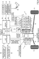
- FIG. 1 is a schematic configuration diagram illustrating a vehicle 1 that has a power train 2
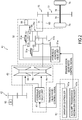
- FIG. 2 is a schematic configuration diagram illustrating an auxiliary transmission mechanism 51 according to a first embodiment.
- the power train 2 includes an engine 3, a torque converter 31 that includes a lock-up clutch 34, a CVT (belt-type automatic transmission) 41, a final drive gear 72, a differential gear 73, and a drive shaft 74.
- CVT belt-type automatic transmission
- FIG. 1 air is introduced from an intake passage 4 to a gasoline engine 3 as a driving source to be supplied to a combustion chamber 6 passing through an intake port 5 of each cylinder.
- An amount of the air supplied to the combustion chamber 6 is adjusted by a degree of opening of a throttle valve 11, which is included in the intake passage 4 and electronically controlled, (hereinafter referred to as "a throttle valve opening").
- the throttle valve opening of the throttle valve 11 is controlled by a throttle motor 12.
- the actual throttle valve opening is detected by a throttle sensor 13 and input to an engine controller 21.
- Each intake port 5 includes a fuel injection valve 7.
- the fuel injection valve 7 intermittently supplies fuel toward the air flowing through the intake port 5.
- the gasoline engine 3 includes ignition plugs 8 facing the combustion chambers 6. The air flowing into the combustion chambers 6 is mixed with the fuel to constitute air-fuel mixture.
- the engine controller 21 cuts off a primary-side current of an ignition coil at a predetermined time before a compression top dead center to cause the ignition plug 8 to generate a spark. This ignites the air-fuel mixture inside the combustion chamber 6. The gas burnt by this ignition is discharged to an exhaust passage (not illustrated).
- the vehicle 1 includes the engine controller 21 to control the engine 3.
- a signal of an accelerator position an amount of depression of an accelerator pedal 22
- a signal of a crank angle from a crank angle sensor an engine rotation speed sensor
- a signal of an intake air amount from an air flow meter 25 are input.
- the rotation speed of the engine 2 is calculated with the signal from the crank angle sensor 24.
- the engine controller 21 calculates a target intake air amount and a target fuel injection amount on the basis of these signals and commands the throttle motor 12 and the fuel injection valve 7 of each cylinder to obtain the target intake air amount and the target fuel injection amount.
- the torque converter 31 includes a pump impeller 32 and a turbine runner 33.
- the CVT 41 includes a forward-reverse switching mechanism 42, a variator 43, and the auxiliary transmission mechanism 51.
- the variator 43 includes a primary pulley 44, a secondary pulley 45, and a steel belt 46 that is stretched around these pulleys 44 and 45.
- the primary pulley 44 and the secondary pulley 45 are supplied with hydraulic oil.
- the width of the pulley is configured to be freely changed corresponding to the pressure of the hydraulic oil (hereinafter, the pressure of the hydraulic oil is simply referred to as "hydraulic"). This ensures to control the hydraulic supplied to the primary pulley 44 and the hydraulic supplied to the secondary pulley 45 to steplessly change the transmission gear ratio of the variator 43.
- the auxiliary transmission mechanism 51 disposed in series with respect to the variator 43 is composed of, as illustrated in FIG. 2 , a case 51a, a compound sun gear 51b, a carrier 51c, a ring gear 51d, and similar parts, and a Ravigneaux type planetary gear mechanism that includes a frictional engagement element (55, 56, and 57). That is, the auxiliary transmission mechanism 51 is a stepwise variable transmission mechanism that couples to drive the secondary pulley 45 to the compound sun gear 51b to set the sun gear 51b input, and couples to drive the carrier 51c to a transmission output shaft 71 to set the carrier 51c output. It should be noted that, this embodiment is not limited to a case where the auxiliary transmission mechanism 51 is configured of the Ravigneaux type planetary gear mechanism.
- the above-described frictional engagement element is composed of a low and reverse brake (hereinafter, the brake is referred to as “a first speed clutch”) 55, a high clutch (hereinafter, the clutch is referred to as “a second speed clutch”) 56, and a reverse brake 57.
- the sun gear 51b is secured to the case 51a via the first speed clutch 55, and the carrier 51c is coupled to drive to the ring gear 51d via the second speed clutch 56.
- the ring gear 51 d is secured to the case 51a via the reverse brake 57.
- the auxiliary transmission mechanism 51 is configured to supply also the first speed clutch 55 (first engagement portion), the second speed clutch 56 (second engagement portion) and the reverse brake 57 with the hydraulic oil, and configured to freely engage and release each frictional engagement element corresponding to the hydraulic supplied to the frictional engagement elements. This ensures the auxiliary transmission mechanism 51 to control the hydraulic supplied to the first speed clutch 55, the second speed clutch 56, and the reverse brake 57 to choose a first forward speed, a second forward speed, and a reverse speed.
- the auxiliary transmission mechanism 51 engages the first speed clutch 55 and releases the second speed clutch 56. In a case of choosing the second forward speed, the auxiliary transmission mechanism 51 releases the first speed clutch 55 and engages the second speed clutch 56.
- the auxiliary transmission mechanism 51 includes at least two clutches of the clutch 55 and the clutch 56, and shifts the first speed clutch 55 from an engaged state to a released state while shifting the second speed clutch 56 from the released state to the engaged state to ensure the gear shifting from a first speed stage to a second speed stage.
- the rotary driving force of the engine 2 is finally transmitted to vehicle drive wheels 75 via the torque converter 31, the variator 43, the auxiliary transmission mechanism 51, the final drive gear 72, the differential gear 73, and the drive shaft 74.
- the vehicle 1 includes a CVT controller 61 to control the CVT 41 mainly composed of the variator 43 and the auxiliary transmission mechanism 51.
- the CVT controller 61 includes a variator controller 61a and an auxiliary transmission mechanism controller 61b.
- the variator controller 61a calculates a target input rotational speed Ni of the variator 43 to steplessly control a transmission gear ratio Ra of the CVT 41 on the basis of the target input rotational speed Ni.
- the auxiliary transmission mechanism controller 61b calculates a target shift stage of the auxiliary transmission mechanism 51 to control to this target shift stage. That is, the CVT 41 as a whole coordinates the shift control operation of the variator 43 and the shift control operation of the auxiliary transmission mechanism 51 to ensure a targeted transmission gear ratio Io.
- a hydraulic control valve unit 47 includes a plurality of solenoid valves.
- the CVT controller 61 controls ON and OFF of each of the plurality of the solenoid valves via the variator controller 61a to control the hydraulic supplied to the primary pulley 44 and the secondary pulley 45 (usually, only the hydraulic supplied to the primary pulley 44). This ensures the transmission gear ratio of the variator 43 to be steplessly changed.
- a hydraulic control valve unit 51e (hydraulic adjusting means) also includes a plurality of solenoid valves.
- the CVT controller 61 controls ON and OFF of each of the plurality of the solenoid valves via the auxiliary transmission mechanism controller 61b to control the hydraulic supplied to the first speed clutch 55, the second speed clutch 56 and the reverse brake 57. This causes the first forward speed or the second forward speed to be chosen.
- each solenoid valve included in the hydraulic control valve units 47 and 51e is controlled by a command hydraulic provided by the CVT controller 61.
- the vehicle 1 includes the CVT controller 61 to control the CVT 41 composed of the variator 43 and the auxiliary transmission mechanism.
- an input rotational speed Nt from an input rotational speed sensor 61 and an output rotation speed No from an output rotational speed sensor 62 are input.
- the input rotational speed is also a rotation speed of the turbine runner 33 (turbine rotation speed) because an input shaft of the variator 43 is coupled to the turbine runner 33.
- the CVT controller 61 calculates a vehicle speed VSP on the basis of the output rotation speed No, the number of teeth of the final drive gear 72, the number of teeth of the differential gear 73, and an effective tire radius of the drive wheel 75 to steplessly control the transmission gear ratio of the CVT 41 corresponding to a driving condition of the vehicle 1 determined by the vehicle speed VSP and a throttle valve opening TVO.
- the CVT controller 61 is coupled to the above-described engine controller 21 by a CAN (Controller Area Network). Via the CAN communication, the engine controller 21 inputs the engine rotation speed Ne, the throttle valve opening TVO, and a basic engine torque Te0 to the CVT controller 61.
- CAN Controller Area Network
- the torque converter 31 includes the mechanical lock-up clutch 34 that engages and releases the pump impeller 32 and the turbine runner 33.
- a driving range of the vehicle that engages the lock-up clutch 34 is preliminarily determined as a lock-up range (that has the vehicle speed and the throttle position as a parameter).
- the CVT controller 61 engages the lock-up clutch to couple the engine 3 to the CVT 41 in a direct-coupled state when the driving condition of the vehicle is in the lock-up range, and releases the lock-up clutch 34 when the driving condition of the vehicle is not in the lock-up range.
- the torque converter 31 does not absorb the torque. Then, the fuel consumption is improved by that amount.
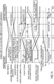
- FIG. 3 is a timing chart of a comparative embodiment illustrating a change during a speed shifting of the auxiliary transmission mechanism 51 from the first speed stage to the second speed stage (hereinafter, this during speed shifting is referred to as "during first-to-second speed shifting") under the condition of a constant accelerator position.
- FIG. 3 includes, from the top, a driving force, an auxiliary transmission gear ratio, a variator gear ratio, a CVT total gear ratio, an engine rotation speed, and an engine torque indicating how to change during the first-to-second speed shifting as a model.
- the auxiliary transmission gear ratio of the second line is the transmission gear ratio of the auxiliary transmission mechanism 51
- the variator gear ratio of the third line is the transmission gear ratio of the variator 43
- the CVT total gear ratio of the fourth line is the transmission gear ratio of the entire CVT 41.
- the torque phase is a phase that distributes an input torque of the auxiliary transmission mechanism 51 to the first speed clutch 55 (the first engagement portion) and the second speed clutch 56 (the second engagement portion) to perform the changeover of the torque.
- the auxiliary transmission gear ratio is up-shifted in the inertia phase.
- the variator gear ratio is changed while the variator gear ratio is down-shifted by the amount of the change of the auxiliary transmission gear ratio.
- the inertia phase is a phase where the input rotational speed Nin of the auxiliary transmission mechanism 51 transitions from the rotation speed before the changeover of the torque to the rotation speed after the changeover of the torque. This cancels the change of the auxiliary transmission gear ratio and the change of the variator gear ratio to achieve a smooth gear shifting as if there is no change in the CVT total gear ratio.
- a clutch engagement shock is proved to generate because an acceleration in the vehicle front-rear direction temporarily changes during the first-to-second speed shifting. That is, the acceleration in the vehicle front-rear direction decreases compared with immediately before the changeover of the torque in the torque phase, and the acceleration in the vehicle front-rear direction increases to return to the value immediately before the changeover of the torque in the subsequent inertia phase.
- the acceleration in the vehicle front-rear direction temporarily changes in a negative direction during the torque phase and the inertia phase, a driver feels this as a shock.
- the driving force transitions from the driving force of the first speed stage to the driving force of the second speed stage in the torque phase.
- the decrease of the driving force in accordance with the transition causes the acceleration in the vehicle front-rear direction (in FIG. 3 , approximately referred to as "front-rear G") to temporarily change to negative.
- front-rear G the acceleration in the vehicle front-rear direction
- down-shifting of the variator gear ratio causes the driving force to recover to the driving force before the changeover of the torque.
- front-rear G drag that temporarily changes to negative causes the driver to identically react to a sudden stop of the vehicle to weaken the driving sense.
- the torque capacity of the first speed stage is larger than the torque capacity of the second speed stage. Then, the transition from the torque capacity of the first speed stage to the torque capacity of the second speed stage without changing the engine rotation speed reduces the torque capacity to generate a deceleration shock corresponding to the amount of the decrease of the torque capacity.
- the CVT controller 61 is configured to command the engine controller 21 (the engine torque control means) to increase the engine torque from the basic engine torque Te0 during the first-to-second speed shifting. This will be described by referring to FIG. 4 .
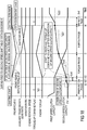
- FIG. 4 is a timing chart illustrating a change during the first-to-second speed shifting under the condition that the accelerator position is constant according to the first embodiment.
- FIG. 4 includes, from the top, the acceleration in the vehicle front-rear direction, the auxiliary transmission gear ratio, the variator gear ratio, the CVT total gear ratio, the engine rotation speed, the engine torque, a first speed clutch command hydraulic, and a second speed clutch command hydraulic indicating how to change during the first-to-second speed shifting as a model.
- the first speed clutch command hydraulic is a command hydraulic provided to the first speed clutch 55
- the second speed clutch command hydraulic is a command hydraulic provided to the second speed clutch 56.
- like reference numerals designate like elements as in FIG. 3 .
- FIG. 3 indicates the change of the driving force on the top line
- FIG. 4 indicates the change of the acceleration in the vehicle front-rear direction on the top line.
- the change of the driving force indicated on the top line in FIG. 3 is similar to the change of the acceleration indicated on the top line in FIG. 4 .
- "2nd front-rear G" is an acceleration in the vehicle front-rear direction (front-rear G) at a timing of t3 where the second speed clutch 56 completes to be engaged. This acceleration is the maximum acceleration generated during the first-to-second speed shifting.
- the CVT controller 61 is configured to additionally have a function as command means, and a torque-up command flag is additionally introduced as illustrated in the sixth line of FIG. 4 .
- the torque-up command flag is set by the CVT controller 61.
- the torque-up command flag is transmitted from the CVT controller 61 to the engine controller 21 as a torque-up command as illustrated in FIG. 1 .
- the above-described command means is composed of two command means of torque-up command means performed in the torque phase and torque-down command means performed in the inertia phase. That is, the CVT controller 61 as the torque-up command means commands to linearly increase the engine torque from the basic engine torque Te0 in the torque phase as illustrated in the seventh line of FIG. 4 .
- the CVT controller 61 as the torque-down command means commands to linearly decrease the engine torque to return to the basic engine torque Te0 in the subsequent inertia phase as illustrated in the seventh line of FIG. 4 .
- the CVT controller 61 uses the engine controller 21 to increase the engine torque from the basic engine torque Te0. This reduces the change of the acceleration in the vehicle front-rear direction to the negative side generated during the first-to-second speed shifting. Then, the gear shift shock generated in accordance with the changeover of the clutch during the first-to-second speed shifting can be improved.
- increasing the engine torque from the basic engine torque Te0 includes increasing a torque-up command value Tup from zero, and decreasing the torque-up command value Tup to zero after increasing the torque-up command value Tup to a maximum value Tupmx.
- increasing the torque-up command value Tup from zero is referred to as “torque-up”
- decreasing the torque-up command value Tup to zero is referred to as “torque-down,” in other words.
- the above-described torque-up command value Tup is the amount of the increase from the basic engine torque Te0.
- the change of the torque-up command value Tup shows a triangular shape in the whole of the torque phase and the inertia phase as illustrated in the seventh line of FIG. 4 .
- the engine torque increases by the area of the triangular shape compared with the case of the comparative embodiment illustrated in FIG. 3 .
- the torque-up command value Tup is calculated in the CVT controller 61 side, and the calculated torque-up command value Tup is transmitted to the engine controller 21.
- the engine controller 21 that receives the torque-up command value Tup adds the amount of the torque-up command value Tup to the basic engine torque Te0, that is, uses the following formula, to calculate an engine torque command value Te (described later).
- Te Te 0 + Tup
- the reason to configure the change of the torque-up command value Tup to show the triangular shape is that, since the change of the acceleration in the vehicle front-rear direction (front-rear G) shows an inverted triangular shape as illustrated in the top line of FIG. 4 , the shape of the change of the torque-up command value Tup is corresponded. That is, as illustrated in the top line of FIG. 4 by a dashed line, in the torque phase, the acceleration in the vehicle front-rear direction (front-rear G) linearly decreases (or can be considered to linearly decrease). As illustrated in the top line of FIG.
- the acceleration in the vehicle front-rear direction linearly increases to return to the state before the gear shifting (or can be considered to linearly increase).
- the change of the acceleration in the vehicle front-rear direction shows an inverted triangular shape in the whole of the torque phase and the inertia phase. Since the acceleration in the vehicle front-rear direction is proportionate to the driving force, the change of the driving force also shows an inverted triangular shape.
- the torque-up command value Tup in the triangular shape is provided. As illustrated in the top line of FIG.
- the CVT controller 61 (the torque-up command means) to reduce the decrease of the acceleration in the vehicle front-rear direction generated in the torque phase.
- the CVT controller 61 (the torque-down command means) can reduce the increase of the acceleration in the vehicle front-rear direction generated in the inertia phase.
- the change of the acceleration in the vehicle front-rear direction in the case of the embodiment is indicated by the solid line
- the change of the acceleration in the vehicle front-rear direction in the case of the comparative embodiment is indicated by the dashed line by overlapping.
- the acceleration in the vehicle front-rear direction (2nd front-rear G) at an engagement completion timing (t3) of the second speed clutch 56 is decreased compared with the case of the comparative embodiment.
- the acceleration in the vehicle front-rear direction at the engagement completion timing (t3) of the second speed clutch 56 depends on the torque-up command value Tup at t3 (that is, the maximum value Tupmx of the torque-up command value).
- the timing where the CVT controller 61 (the torque-up command means) starts to increase the torque-up command value Tup (increase the engine torque from the basic engine torque Te0) is the timing of the start of the torque phase.
- the reason is as follows. That is, a clutch engagement capacity of the second clutch 56 (hereinafter, simply referred to as "second clutch engagement capacity") is generated from the timing of the start of the torque phase, and then, the acceleration in the vehicle front-rear direction decreases.
- the timing of the start of increasing the torque-up command value Tup is configured to match the timing of the start of the torque phase.
- the timing where the CVT controller 61 (the torque-down command means) starts to decrease the torque-up command value Tup (engine torque) is the timing of the start of the inertia phase.
- the variator 43 acts from the timing of the start of the inertia phase to achieve a target value of the transmission gear ratio of the entire CVT, and then, the acceleration in the vehicle front-rear direction increases. Accordingly, if the timing of the start of decreasing the torque-up command value Tup deviates to before or after the timing of the start of the inertia phase, the increase of the acceleration in the vehicle front-rear direction generated from the timing where the variator 43 acts fails to be reduced with high accuracy.
- the timing of the start of decreasing the torque-up command value Tup is configured to match the timing of the start of the inertia phase.
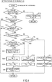
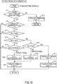
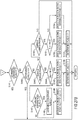
- the flowchart in FIG. 5 is a flowchart to set the torque-up command flag, and executed by the CVT controller 61 at regular time intervals (such as every 10 ms).
- the CVT controller 61 sets the torque-down command flag
- the CVT controller 61 uses the throttle valve opening TVO and the basic engine torque Te0 transmitted from the engine controller 21.
- Step S1 the CVT controller 61 determines whether it is during the first-to-second speed shifting.
- the CVT controller 61 includes a gear shifting diagram (not illustrated) that has the vehicle speed VSP as a horizontal axis, and the input rotational speed Ni as a vertical axis.
- the auxiliary transmission mechanism controller 61b provides a first clutch command hydraulic and a second clutch command hydraulic respectively illustrated in the eighth line and the ninth line of FIG.
- Step S2 the CVT controller 61 determines whether it is during the preparation phase. Whether it is during the preparation phase can be determined by the first speed clutch command hydraulic and the second speed clutch command hydraulic. When it is during the preparation phase, the CVT controller 61 terminates the current process.
- the CVT controller 61 determines that the phase has transitioned to the phase after the preparation phase (the torque phase, the inertia phase, the termination phase), and advances the process to Step S3.
- the CVT controller 61 refers to a torque-up termination flag (initially set to zero when the engine is started).
- the CVT controller 61 advances the process to Steps S4 and S5.
- Step S4 the CVT controller 61 determines whether the current process is the torque phase.
- Step S5 the CVT controller 61 determines whether the previous process is the torque phase. Whether it is the torque phase can be determined by the first speed clutch command hydraulic and the second speed clutch command hydraulic.
- the CVT controller 61 advances the process to Steps S6 and S7.
- Steps S6 and S7 are steps that linearly increases the torque-up command value Tup from zero when the phase transitions to the torque phase.
- the CVT controller 61 puts zero of the initial value to "a Tup (previous)" [Nm] as the previous torque-up command value.
- the CVT controller 61 calculates a value that adds a predetermined value ⁇ T1 [Nm] to "the Tup (previous)," which the zero is put to and is the previous torque-up command value, as a current torque-up command value Tup.
- the above-described predetermined value ⁇ T1 is a value to determine the gradient of the increase of the torque-up command value in the torque phase, and predetermined.
- Step S4 the CVT controller 61 determines that the phase has transitioned to the phase after the torque phase (the inertia phase, the termination phase), and advances the process to Step S9.
- Step S9 the CVT controller 61 determines whether the phase is the inertia phase. Whether the phase is the inertia phase can be determined by the first speed clutch command hydraulic and the second speed clutch command hydraulic. When the phase is the inertia phase, the CVT controller 61 advances the process to Step S10.
- Step S10 is a step that linearly decreases the torque-up command value Tup from the maximum value (the torque-up command value has the maximum value at the timing of the termination of the torque phase) when the phase transitioned to the inertia phase. That is, in Step S10, the CVT controller 61 calculates a value that subtracts a predetermined value ⁇ T2 [Nm] from "the Tup (previous), " which is the previous torque-up command value, as the current torque-up command value Tup.
- the above-described predetermined value ⁇ T2 is a value to determine the gradient of the decrease of the torque-up command value in the inertia phase, and predetermined.
- the CVT controller 61 transmits the torque-up command flag (the torque-up command), which is set in such way, to the engine controller 21 via the CAN communication with the torque-up command value Tup (see FIG. 1 ).
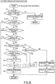
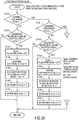
- the flowchart in FIG. 6 is a flowchart to calculate an engine torque command value Te, and executed by the engine controller 21 at regular time intervals (such as every 10 ms).
- the engine controller 21 uses the torque-up command flag and the torque-up command value Tup transmitted from the CVT controller 61 as the torque-up command.
- Step S21 the engine controller 21 searches a map that includes the content of FIG. 7 with the engine rotation speed Ne [rpm], an intake air amount Qa detected by the air flow meter 25, and the throttle valve opening TVO to calculate the basic engine torque Te0 [Nm].
- the basic engine torque Te0 is a value that becomes larger as the increase of the intake air amount Qa under the condition where the engine rotation speed Ne and the throttle valve opening TVO are constant.
- the basic engine torque Te0 is a value that becomes larger as the increase of the engine rotation speed Ne under the condition where the intake air amount Qa and the throttle valve opening TVO are constant.
- the basic engine torque Te0 is a value that becomes larger as the increase of the throttle valve opening TVO under the condition where the intake air amount Qa and the engine rotation speed Ne are constant.
- Step S22 the engine controller 21 refers to the torque-up command flag.
- the torque-up command flag is transmitted from the CVT controller 61.
- the engine controller 21 determines that the torque-up command has not been instructed.
- the engine controller 21 advances the process to Step S24 to put the basic engine torque Te0 to the engine torque command value Te [Nm] as it is.
- Step S23 the engine controller 21 calculates a value that adds the torque-up command value Tup [Nm] to the basic engine torque Te0 as the engine torque command value Te [Nm]. That is, the engine controller 21 uses the above-described formula (1) to calculate the engine torque command value Te. This causes the engine torque to be linearly increased from the basic engine torque Te0 in the torque phase. In the inertia phase, on the other hand, the engine torque is linearly decreased from the value at the timing of the termination of the torque phase to be returned to the basic engine torque Te0 at the timing of the termination of the inertia phase.
- Step S25 the engine controller 21 outputs the engine torque command value Te.
- the engine controller 21 calculates the target intake air amount on the basis of the engine torque command value Te.
- the engine torque command value Te increases by the amount of the torque-up command value Tup
- the target intake air amount increases by the amount of the torque-up command value Tup
- the throttle valve opening TVO increases.
- the throttle valve opening TVO increases, the intake air amount Qa increases, and the fuel injection amount increases by the amount of the increase of the intake air amount Qa. This increases the actual engine torque compared with the case of the comparative embodiment where the basic engine torque Te0 is set to the engine torque command value Te as it is.
- the variator 43 (the continuously variable transmission mechanism) configured to steplessly change the transmission gear ratio
- the auxiliary transmission mechanism 51 disposed in series with respect to the variator 43 and the CVT controller 61 (shift control means) are disposed.
- the above-described auxiliary transmission mechanism 51 includes at least two clutches of 55 and 56 (engagement portion). Then, the auxiliary transmission mechanism 51 shifts the first speed clutch 55 from the engaged state to the released state, and shifts the second speed clutch 56 from the released state to the engaged state to ensure the gear shifting from the first speed stage to the second speed stage.
- the above-described CVT controller 61 sets the target value of the transmission gear ratio of the whole of the variator 43 and the auxiliary transmission mechanism 51 on the basis of the operating state of the vehicle.
- the CVT controller 61 controls the variator 43 so as to achieve the target value.
- the above-described engine controller 21 controls the engine 3 so as to obtain the basic engine torque Te0 corresponding to the operating state of the vehicle.
- the above-described CVT controller 61 as the command means commands the engine controller 21 to increase the engine torque from the basic engine torque Te0 during the first-to-second speed shifting.
- the engine controller 21 is used to increase the engine torque from the basic engine torque Te0 during the first-to-second speed shifting by use of the auxiliary transmission mechanism 51.
- the command means is configured of the torque-up command means and the torque-down command means.
- the above-described torque-up command means linearly increases the engine torque from the basic engine torque Te0.
- the above-described torque-down command means linearly decreases the engine torque after the torque-up command means increased the engine torque, and commands to return the engine torque to the basic engine torque Te0. This ensures to individually reduce the decrease of the acceleration in the vehicle front-rear direction generated by the torque-up command means in the torque phase and the increase of the acceleration in the vehicle front-rear direction generated by the torque-down command means in the inertia phase.
- the timing where the CVT controller 61 (the torque-up command means) starts to increase the engine torque from the basic engine torque Te0 is the timing of the start of the torque phase. This reduces the decrease of the acceleration in the vehicle front-rear direction, which generates from the timing of the generation of the second speed clutch engagement capacity, with high accuracy.
- the timing where the CVT controller 61 (the torque-down command means) starts to decrease the engine torque is the timing of the start of the inertia phase. This reduces the increase of the acceleration in the vehicle front-rear direction, which generates from the timing that the variator 43 acts at, with high accuracy.
- FIG. 8A and FIG. 8B are timing charts illustrating the changes during the first-to-second speed shifting of a second embodiment.
- FIG. 8A mainly indicates the torque-up (increasing the torque-up command value Tup from zero) in the torque phase.
- FIG. 8B mainly indicates the torque-down (decreasing the torque-up command value Tup to zero) in the inertia phase.
- like reference numerals denote like elements as in FIG. 4 of the first embodiment.
- the CVT controller 61 increases the torque-up command value Tup in synchronization with a torque phase clutch engagement capacity increase rate R1 in a torque-up phase.
- the torque phase clutch engagement capacity increase rate R1 is a value additionally introduced in the second embodiment. That is, the torque phase clutch engagement capacity increase rate R1 is an increase rate of the second speed clutch engagement capacity in the torque phase.
- the second speed clutch engagement capacity is a transfer torque [Nm] that the second speed clutch 56 generates. The second speed clutch engagement capacity is zero at the start of the engagement of the second clutch 56, and maximum at the termination of the engagement of the second clutch 56. Therefore, the torque phase clutch engagement capacity increase rate R1 [%] is a rate that linearly increases from the start of the torque phase to the termination of the torque phase as 0% at the start timing of the torque phase and 100% at the termination timing of the torque phase.
- the reason to increase the torque-up command value Tup (increase the engine torque) from zero in synchronization with the torque phase clutch engagement capacity increase rate R1 is as follows. That is, the maximum value Tupmx of the torque-up command value, which is linearly increased from the start timing of the torque phase, is predetermined. In this case, even if the CVT controller 61 linearly increases the torque-up command value Tup from the start timing of the torque phase, the torque-up command value is not necessarily to just reach the maximum value Tupmx at the termination timing of the torque phase.
- the torque-up command value Tup reaches the maximum value Tupmx of the torque-up command value deviating to before or after the termination timing of the torque phase, the decrease of the acceleration in the vehicle front-rear direction generated in the torque phase fails to be reduced with high accuracy.
- the timing of the start and the termination of the torque phase can be preliminarily obtained by the second speed clutch command hydraulic. Therefore, to reach the torque-up command value to the maximum value Tupmx just at the termination timing of the torque phase, the torque-up command value Tup is increased from zero in synchronization with the torque phase clutch engagement capacity increase rate R1.
- the maximum value Tupmx of the torque-up command value which the CVT controller 61 (the torque-up command means) increases, as illustrated in FIG. 8A and FIG. 8B , is determined corresponding to the currently generated engine torque.
- the maximum value Tupmx of the torque-up command value is again defined as "a reached torque-up amount" Treach1.
- the currently generated engine torque is the basic engine torque Te0 [Nm].
- the reached torque-up amount Treach1 [Nm] is calculated by the following formula.
- Treach 1 Te 0 ⁇ C 1
- C1 constant
- the setting method of the constant C1 of the formula (3) is as follows.
- the constant C1 is set to approximately 1.8 matching with the ratio of the gear ratio of the first speed stage and the gear ratio of the second speed stage (ratio between the gear stages) because the ratio between the gear stages is approximately 1.8 times. That is, it is only necessary to set the constant C1 such that the change of the acceleration in the vehicle front-rear direction generated during the first-to-second speed shifting to the negative side is reduced compared with the case of the comparative embodiment.
- Tup 1 Treach 1 ⁇ R 1 / 100
- the processing in the torque phase is enhanced to the inertia phase. That is, in the second embodiment, as illustrated in FIG. 8A and FIG. 8B , the CVT controller 61 (the torque-down command means) decreases the torque-up command value Tup from the maximum value in synchronization with an inertia phase progress rate R2 [%] in the inertia phase.
- the inertia phase progress rate R2 is also the value additionally introduced in the second embodiment.
- the inertia phase progress rate is a rate that linearly increases from the start of the inertia phase to the termination of the inertia phase as 0% at the start timing of the inertia phase and 100% at the termination timing of the inertia phase.
- the reason to decrease the torque-up command value Tup (decrease the engine torque) from the reached torque-up amount Treach1 in synchronization with the inertia phase progress rate R2 is as follows. That is, even if the CVT controller 61 linearly decreases the torque-up command value Tup from the start timing of the inertia phase, the torque-up command value is not necessarily to return to the basic engine torque Te0 just at the termination timing of the inertia phase. If the torque-up command value Tup returns to the basic engine torque Te0 deviating to before or after the termination timing of the inertia phase, the increase of the acceleration in the vehicle front-rear direction generated in the inertia phase fails to be reduced with high accuracy.
- the timing of the start and the termination of the inertia phase can be preliminarily obtained by the second speed clutch command hydraulic. Therefore, to return the torque-up command value to the basic engine torque Te0 just at the termination timing of the inertia phase, the torque-up command value Tup is decreased from the reached torque-up amount Treach1 in synchronization with the inertia phase progress rate R2.
- Tup 2 Treach 1 ⁇ 1 ⁇ R 2 / 100
- the reason to introduce the above-described torque phase clutch engagement capacity increase rate is as follows. That is, the decrease gradient of the acceleration in the vehicle front-rear direction in the torque phase (or the maximum acceleration in the vehicle front-rear direction generated during the first-to-second speed shifting) depends on the engagement method of the second speed clutch 56. For example, an early engagement of the second speed clutch 56 makes the decrease gradient of the acceleration in the vehicle front-rear direction in the torque phase large (sharp), on the other hand, a late engagement of a second speed clutch 26 makes the decrease gradient of the acceleration in the vehicle front-rear direction in the torque phase small (gentle).
- the torque phase clutch engagement capacity increase rate is introduced as the substitute for the decrease gradient of the acceleration in the vehicle front-rear direction in the torque phase.
- the reason to introduce the inertia phase progress rate is as follows. That is, the increase gradient of the acceleration in the vehicle front-rear direction in the inertia phase depends on an inertia torque (inertia moment) of the second clutch 56. For example, a small inertia torque (inertia moment) of the second clutch 56 makes the increase gradient of the acceleration in the vehicle front-rear direction in the inertia phase large, on the other hand, a large inertia torque (inertia moment) of the second clutch 56 makes the increase gradient of the acceleration in the vehicle front-rear direction in the inertia phase small.
- the inertia phase progress rate is introduced as the substitute for the increase gradient of the acceleration in the vehicle front-rear direction in the inertia phase.
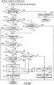
- the flowchart in FIG. 9 is a flowchart to set the torque-up command flag of the second embodiment, and this flowchart is executed by the CVT controller 61 at regular time intervals (such as every 10 ms).
- like reference numerals designate like elements as in the flowchart in FIG. 5 of the first embodiment.
- Step S31 the CVT controller 61 uses the following formula including the basic engine torque Te0 as the current engine torque and the constant C1 [abstract number] to calculate the reached torque-up amount Treach1 [Nm].
- Treach 1 Te 0 ⁇ C 1
- Step S32 the CVT controller 61 use the following formula including the reached torque-up amount Treach1 and the torque phase clutch engagement capacity increase rate R1 [%] to calculate the torque-up command value Tup1 [Nm] in the case where the torque-up amount is provided with a straight line characteristic in the torque phase. Then, the CVT controller 61 transfers the value of the Tup1 to the torque-up command value Tup in Step S33.
- Tup 1 Treach 1 ⁇ 1 / 100
- Steps S4 and S5 when the current process is the torque phase and the previous process is also the torque phase, that is, when the phase is continuously the torque phase, the CVT controller 61 executes the operations of Steps S32 and S33 skipping Step S31. This increases the torque-up command value Tup from the start timing of the torque phase in synchronization with the torque phase clutch engagement capacity increase rate R1.
- Step S4 the CVT controller 61 uses the following formula including the reached torque-up amount Treach1 and the inertia phase increase rate R2 [%] to calculate the torque-up command value Tup2 [Nm] in the case where the torque-up amount is provided with the straight line characteristic in the inertia phase. Then, the CVT controller 61 transfers the value of the Tup2 to the torque-up command value Tup in Step S35.
- Tup 2 Treach 1 1 ⁇ R 2 / 100
- Step S9 the CVT controller 61 executes the operations of Steps S34 and S35. This decreases the torque-up command value Tup from the start timing of the inertia phase in synchronization with the inertia phase increase rate R2.
- the CVT controller 61 (increase rate setting means) that sets the torque phase clutch engagement capacity increase rate R1 is disposed. Then, the CVT controller 61 (the torque-up command means) commands the engine controller 21 to increase the torque-up command value Tup (increase the engine torque) from zero in synchronization with the torque phase engagement clutch capacity increase rate R1. This causes the torque-up command value to reach the reached torque-up amount Treach1 (the maximum value of the torque-up command value) just at the termination timing of the torque phase. Then, the decrease of the acceleration in the vehicle front-rear direction generated in the torque phase can be reduced with high accuracy.
- the reached torque-up amount Treach1 (the maximum value of the torque-up command value increased by the torque-up command means) is determined corresponding to the basic engine torque Te0. This ensures to provide the appropriate maximum value (Treach1) of the torque-up command value Tup corresponding to the maximum value of the acceleration in the vehicle front-rear direction generated during the first-to-second speed shifting if the basic engine torque Te0 during the first-to-second speed shifting differs.
- the CVT controller 61 (progress rate setting means) that sets the inertia phase progress rate R2 is disposed. Then, the CVT controller 61 (the torque-down command means) commands the engine controller 21 to decrease the torque-up command value Tup (decrease the engine torque) from the reached torque-up amount Trech1 in synchronization with the inertia phase progress rate R2. This causes the torque-up command value to return to the basic engine torque Te0 just at the termination timing of the inertia phase. Then, the decrease of the acceleration in the vehicle front-rear direction generated in the inertia phase can be reduced with high accuracy.
- FIG. 10 is a timing chart illustrating the change during the first-to-second speed shifting of a third embodiment.
- FIG. 10 mainly indicates the torque-up (increasing the torque-up command value Tup from zero) in the torque phase.
- like reference numerals denote like elements as in FIG. 8A of the second embodiment.
- the torque-up command value Tup starts to be increased from zero at the start timing of the torque phase.
- the CVT controller 61 (the torque-up command means) starts the command to increase the torque-up command value Tup at the timing of a t11 before the start of the torque phase.
- the reason that the command to increase the torque-up command value Tup is started at the timing of the t11 before the start of the torque phase is as follows. That is, when the CVT controller 61 commands the engine controller 21 to increase the engine torque from the basic engine torque Te0, a response lag exists from the command timing to the start of the actual increase of the engine torque. This is because the engine torque does not increase immediately even if the engine controller 21 increases the throttle valve opening TVO by a certain amount to increase the intake air amount at the timing of receiving the command.
- the process is as follows; the intake air increased by the throttle valve 11 reaches the combustion chamber 6 with a supply delay corresponding to the amount of the volume from the throttle valve 11 to the intake port 5, and is mixed with the fuel from the fuel injection valve 7 to be the air-fuel mixture. Then, this air-fuel mixture is ignited to burn by the ignition plug 8 and increases the engine torque.
- the increase of the torque-up command value Tup is started at the start timing of the torque phase without considering the above-described supply delay of the intake air, the actual engine torque increases with the delay to the start timing of the torque phase. Then, the decrease of the acceleration in the vehicle front-rear direction fails to be reduced in the period of the delay of the increase of the actual engine torque. Therefore, starting the command to increase the torque-up command value Tup at the timing of the t11 before the start of the torque phase increases the actual engine torque without delaying to the start timing of the torque phase even if the supply of the intake air delays.
- the CVT controller 61 achieves the reached torque-up amount (the maximum value of the torque-up command value to be increased) at the timing of a t12 before the termination of the torque phase.
- the reason that causes the engine torque to reach the reached torque-up amount Treach2 (the maximum value of the torque-up command value to be increased) at the timing of the t12 before the termination of the torque phase is as follows. That is, if the command of the increase is terminated at the termination timing of the torque phase without considering the above-described supply delay of the intake air, the engine torque reaches the reached torque-up amount Treach2 with the delay to the termination timing of the torque phase. Then, the decrease of the acceleration in the vehicle front-rear direction fails to be reduced in the period of the delay to reach the reached torque-up amount Treach2. Therefore, the CVT controller 61 causes the engine torque to reach the reached torque-up amount Treach2 before the termination of the torque phase. This ensures the engine torque to reach the reached torque-up amount Treach2 without delaying to the termination timing of the torque phase even if the supply of the intake air delays.
- the reached torque-up amount Treach1 is calculated with the basic engine torque Te0 and the constant C1.
- the reached torque-up amount Treach2 is determined with a currently generated engine torque (Te1) and a coefficient C2 corresponding to the engine rotation speed Ne. That is, the following formula is used to calculate the reached torque-up amount Treach2.
- Treach 2 Te 1 ⁇ C 2
- the basic engine torque is described as "Te1" differing from the first embodiment.
- the calculation method of the basic engine torque is different from one another in the first embodiment and the second embodiment. That is, in the first embodiment, the basic engine torque Te0 is calculated even with the engine rotation speed Ne as the parameter (see FIG. 7 ). On the other hand, in the second embodiment, the basic engine torque is calculated without the engine rotation speed Ne as the parameter (described later).
- the reached torque-up amount in the second embodiment is described as "Treach2."
- the reason that the coefficient C2 is set to the value corresponding to the engine rotation speed Ne as described above is as follows. That is, the maximum value of the acceleration in the vehicle front-rear direction generated during the first-to-second speed shifting is determined with the currently generated basic engine torque and the difference between the driving force of the first speed stage and the driving force of the second speed stage. Then, as described above, the difference between the driving force of the first speed stage and the driving force of the second speed stage can be preliminarily obtained by the specification of the auxiliary transmission mechanism 51. In this case, there is a method to calculate the basic engine torque Te1 without the engine rotation speed Ne as the parameter. For example, as illustrated in FIG. 11 , assume that the basic engine torque Te1 is adapted at a predetermined engine rotation speed Ne1.
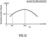
- the predetermined engine rotation speed in this case is referred to an "adapted rotation speed," as illustrated in FIG. 12
- the actual engine torque is different from the basic engine torque Te1.
- the reached torque-up amount corresponding to the maximum value of the acceleration in the vehicle front-rear direction during the first-to-second speed shifting (the maximum value of the torque-up command value) is not provided, and the engine torque lacks to the reached torque-up amount.
- the acceleration in the vehicle front-rear direction generated during the first-to-second speed shifting fails to be reduced.
- determining the reached torque-up amount Treach2 corresponding to the engine rotation speed Ne and the basic engine torque Te1 ensures the reached torque-up amount corresponding to the maximum value of the acceleration in the vehicle front-rear direction during the first-to-second speed shifting to be obtained without excess or deficiency even if in the case where the basic engine torque Te1 is calculated without considering the engine rotation speed Ne.
- the basic engine torque Te1 is calculated with the intake air amount Qa and the throttle valve opening TVO.
- the influence to the maximum engine torque by the difference of the engine rotation speed Ne is not considered.
- the property of the maximum engine torque in the case where the engine rotation speed Ne is differed under the condition that the intake air amount Qa and the throttle valve opening are constant is not a simple proportional characteristic as illustrated in FIG. 12 . That is, as illustrated in FIG. 12 , the more the Ne increases, the larger the maximum engine torque becomes until the predetermined value Ne2, and after the predetermined value Ne2, the maximum engine torque decreases. Then, the property of a constant C2 with respect to the engine rotation speed Ne is obtained as illustrated in FIG.
- the constant C2 is 1.0 when the engine rotation speed Ne is the adapted rotation speed Ne1.
- the constant C2 is less than 1.0 when the engine rotation speed Ne is a predetermined value Ne3 that is larger than the adapted rotation speed Ne1, and the value where the basic engine torque Te1 is increased by this constant C2 is the reached torque-up amount Treach2. This ensures to obtain the reached torque-up amount Treach2 with high accuracy if the engine rotation speed Ne differs.
- the flowchart in FIG. 14 is a flowchart to set the torque-up command flag of the third embodiment, and this flowchart is executed by the CVT controller 61 at regular time intervals (such as every 10 ms).
- like reference numerals designate like elements as in the flowchart in FIG. 9 of the second embodiment.
- Steps S41 and S42 the CVT controller 61 compares an elapsed time x1 from the start timing of the preparation phase with certain time periods ⁇ x1 and ⁇ x2.
- the certain time period ⁇ x1 is a value to start to increase the torque-up command value Tup before the start timing of the torque phase, and predetermined (see the sixth line in FIG. 10 ).
- the certain time period ⁇ T2 is a value to start the inertia phase, and predetermined (see the sixth line in FIG. 10 ).
- the CVT controller 61 determines that the start timing of increasing the torque-up command value Tup has not come yet, and terminates the current process.
- the CVT controller 61 advances the process to Step S43 and following Steps to perform the torque-up (increase the torque-up command value Tup from zero).
- Step S43 the CVT controller 61 searches a table including the content of FIG. 13 with the engine rotation speed Ne to calculate the constant C2 [abstract number].
- Step S44 the CVT controller 61 uses the following formula including the basic engine torque Te1 [Nm] as the current engine torque and the constant C2 to calculate the reached torque-up amount Treach2 [Nm].
- Treach 2 Te 1 ⁇ C 2
- the basic engine torque Te1 of the formula (11) is calculated by searching the map including the content of FIG. 11 with the intake air amount Qa and the throttle valve opening TVO.
- Step S45 the CVT controller 61 uses the following formula including the reached torque-up amount Treach2 and a predetermined time ⁇ x3 to calculate a straight line gradient a1 in the case where the torque-up command value Tup is provided with the straight line characteristic in the torque phase.
- a 1 Treach 2 / ⁇ x 3
- Step S46 the CVT controller 61 uses the following formula including the gradient a1 and the elapsed time x1 from the start timing of the preparation phase to calculate the torque-up command value Tup1 [Nm] in the case where the torque-up command value Tup is provided with the straight line characteristic in the torque phase.
- Tup 1 a 1 ⁇ x 1 ⁇ ⁇ x 1
- the right side of the formula (13), (x1 - ⁇ x1), is the elapsed time from the t11 in FIG. 10 (that is, the elapsed time from the timing to increase the torque command value).
- Step S47 the CVT controller 61 compares the torque-up amount Tup1 with the reached torque-up amount Treach2. When the torque-up amount Tup1 is equal to or less than the reached torque-up amount Treach2, the CVT controller 61 advances the process to Step S33 skipping Step S48 to transfer the value of the Tup1 to the torque-up command value Tup [Nm].
- Step S47 when the torque-up amount Tup1 exceeds the reached torque-up amount Treach2, the CVT controller 61advances the process to Step S48 to input the reached torque-up amount Treach2 to the torque-up amount Tup1. Then, in Step S33, the CVT controller 61 transfers the value of the Tup1 to the torque-up command value Tup. This causes the maximum value of the torque-up command value Tup to be the reached torque-up amount Treach2.
- Steps S41 and S42 when the elapsed time x1 from the start timing of the preparation phase is equal to or more than the certain time period ⁇ x2, the CVT controller 61 advances the process to Step S49 to determine whether the phase is the termination phase. When the phase is not the termination phase, the CVT controller 61 determines that the phase is the inertia phase and advances the process to Steps S34 and S35 to decrease the torque-up command value Tup.
- Step S34 the CVT controller 61 uses the following formula including the reached torque-up amount Treach2 and the inertia phase increase rate R2 [%] to calculate the torque-up command value Tup2 [Nm] in the case where the torque-up command value Tup is provided with the straight line characteristic in the inertia phase. Then, in Step S35, the CVT controller 61 transfers the value of the Tup2 to the torque-up command value Tup.
- Tup 2 Treach 2 1 ⁇ R 2 / 100
- the CVT controller 61 starts to increase the torque-up command value Tup (command to increase the engine torque) at the timing before the start of the torque phase. This ensures to increase the actual engine torque without delaying to the start timing of the torque phase even if the supply of the intake air delays.
- the timing before the start of the torque phase is set corresponding to the delay of the supply of the intake air. Then, the start timing of increasing the torque-up command value Tup can be set with high accuracy in accordance with the supply delay of the intake air.
- the CVT controller 61 (the torque-up command means) causes the engine torque to reach the reached torque-up amount Treach2 (the maximum value of the torque-up command value to be increased) before the termination of the torque phase. This ensures the engine torque to reach the reached torque-up amount Treach2 without delaying to the termination timing of the torque phase even if the supply of the intake air delays.
- the reached torque-up amount Treach2 (the maximum value of the torque-up amount increased by the torque-up command means) is determined corresponding to the engine rotation speed Ne and the basic engine torque Te1. This ensures to provide the reached torque-up amount Treach2 corresponding to the maximum value of the acceleration in the vehicle front-rear direction during the first-to-second speed shifting without excess or deficiency even if in the case where the basic engine torque Te1 is calculated without the engine rotation speed Ne as the parameter (variable).
- FIG. 15 is a timing chart illustrating the change during the first-to-second speed shifting of a fourth embodiment.
- FIG. 15 mainly indicates the torque-down (decreasing the torque-up command value Tup to zero) in the inertia phase.
- like reference numerals denote like elements as in FIG. 8B of the second embodiment.
- the torque-up command value Tup starts to be decreased from the reached torque-up amount Treach1 at the start timing of the inertia phase.
- the CVT controller 61 the torque-down command means starts the command to decrease the torque-up command value Tup at the timing of a t21 before the start of the inertia phase.
- the reason that the command to decrease the torque-up command value Tup is started at the timing of the t21 before the start of the inertia phase is as follows. That is, when the CVT controller 61 commands the engine controller 21 to decrease the engine torque, a response lag exists from the command timing to the start of the actual decrease of the engine torque. This is because the engine torque does not decrease immediately even if the engine controller 21 decreases the throttle valve opening by a certain amount to decrease the intake air amount at the timing of receiving the command.
- the process is as follows; the intake air decreased at the section of the throttle valve 11 reaches the combustion chamber 6 with a supply delay corresponding to the amount of the volume from the throttle valve 11 to the intake port 5, and is mixed with the fuel from the fuel injection valve 7 to be the air-fuel mixture. Then, this air-fuel mixture is ignited to burn by the ignition plug 8 and increases the engine torque. If the decrease of the torque-up command value Tup is started at the start timing of the inertia phase without considering the above-described supply delay of the intake air, the actual engine torque decreases with the delay to the start timing of the inertia phase. The increase of the acceleration in the vehicle front-rear direction fails to be reduced in the period of the delay of the decrease of the actual engine torque.
- starting the command to decrease the torque-up command value Tup at the timing of the t21 before the start of the inertia phase decreases the actual engine torque without delaying to the start timing of the inertia phase even if the supply of the intake air delays.
- the CVT controller 61 (the torque-down command means) returns the engine torque to the basic engine torque Te1 at the timing of a t22 before the termination of the inertia phase.
- the reason to return the engine torque to the basic engine torque Te1 at the timing of the t22 before the termination of the inertia phase is as follows. That is, if the command of the decrease is terminated at the termination timing of the inertia phase without considering the above-described supply delay of the intake air, the engine torque returns to the basic engine torque Te1 with the delay to the termination timing of the inertia phase. Then, the increase of the acceleration in the vehicle front-rear direction fails to be reduced in the period of the delay to return to the basic engine torque Te1. Therefore, returning the engine torque to the basic engine torque Te1 before the termination of the inertia phase returns the engine torque to the basic engine torque Te1 without delaying to the termination timing of the inertia phase even if the supply of the intake air delays.
- the flowchart in FIG. 16 is a flowchart to set the torque-up command flag of the fourth embodiment, and this flowchart is executed by the CVT controller 61 at regular time intervals (such as every 10 ms).
- like reference numerals designate like elements as in the flowchart in FIG. 9 of the second embodiment and FIG. 14 of the third embodiment.
- Step S61 the CVT controller 61 compares the elapsed time x1 from the start timing of the preparation phase with a certain time period ⁇ x5.
- the certain time period ⁇ x5 is a value to start to decrease the torque-up command value Tup before the start timing of the inertia phase, and predetermined.
- the CVT controller 61 determines that the start timing of decreasing the torque-up command value Tup has not come yet, and terminates the current process.
- the CVT controller 61 advances the process to Step S43 and following Steps to perform the torque-down (decrease the torque-up command value Tup to zero).
- Step S43 the CVT controller 61 searches a table including the content of FIG. 13 with the engine rotation speed Ne to calculate the constant C2 [abstract number].
- Step S44 the CVT controller 61 uses the following formula including the basic engine torque Te1 [Nm] as the current engine torque and the constant C2 to calculate the reached torque-up amount Treach2 [Nm].
- Treach 2 Te 1 ⁇ C 2
- the basic engine torque Te 1 of the formula (15) is calculated by searching the map including the content of FIG. 11 with the intake air amount Qa and the throttle valve opening TVO.
- Step S62 the CVT controller 61 uses the following formula including the reached torque-up amount Treach2 and the torque phase engagement clutch capacity increase rate R1 [%] to calculate the torque-up command value Tup1 [Nm] in the case where the torque-up command value Tup is provided with the straight line characteristic in the torque phase. Then, in Step S33, the CVT controller 61 transfers the value of the Tup1 to the torque-up command value Tup.
- Tup 1 Treach 2 ⁇ R 1 / 100
- Step S61 the CVT controller 61 advances the process to Step S49 when the elapsed time x1 from the start timing of the preparation phase is equal to or more than the certain time period ⁇ x5 to determine whether the phase is the termination phase.
- the CVT controller 61 advances the process to Steps S63 to S66 to decrease the torque-up command value Tup.
- Steps S63 to S66 are steps to decrease the torque-up command value Tup in the inertia phase.
- the CVT controller 61 uses the following formula including the reached torque-up amount Treach2 and a predetermined time ⁇ x6 to calculate a straight line gradient a2 in the case where the torque-up command value Tup is provided with the straight line characteristic in the inertia phase.
- a 2 Treach 2 / ⁇ x 6
- the certain time period ⁇ x6 of the formula (17) is predetermined.
- the CVT controller 61 uses the following formula including the gradient a2 and the elapsed time x1 from the start timing of the preparation phase to calculate the torque-up command value Tup2 [Nm] in the case where the torque-up command value Tup is provided with the straight line characteristic in the inertia phase.
- Tup 2 Treach 2 ⁇ a 2 ⁇ x 1 ⁇ ⁇ x 4
- the (x1 - ⁇ x4) of the formula (18) is the elapsed time from the t21 in FIG. 15 (that is, the elapsed time from the timing to decrease the torque command value).
- Step S65 the CVT controller 61 compares the torque-up command value Tup2 with zero.
- the CVT controller 61 advances the process to Step S35 skipping Step S66, and transfers the value of the Tup2 to the torque-up command value Tup.
- Step S65 when the torque-up command value Tup2 is less than zero, the CVT controller 61 advances the process to Step S66 to input zero to the torque-up command value Tup2. Then, the CVT controller 61 transfers the value of the Tup2 to the torque-up command value Tup in Step S35.
- the CVT controller 61 (the torque-down command means) starts the command to decrease the engine torque at the timing before the start of the inertia phase. This ensures to decrease the actual engine torque without delaying to the start timing of the inertia phase even if the response of the intake air delays.
- the timing before the start of the inertia phase is set corresponding to the supply delay of the intake air. Then, the start timing of the decrease of the torque-up command value Tup can be set with high accuracy in accordance with the supply delay of the intake air.
- the CVT controller 61 (the torque-down command means) returns the engine torque to the basic engine torque Te1 before the termination of the inertia phase. This ensures to return the engine torque to the basic engine torque Te1 without delaying to the termination timing of the inertia phase even if the supply of the intake air delays.
- FIG. 17 is a timing chart illustrating the change during the first-to-second speed shifting of the first embodiment as a premise of a fifth embodiment
- FIG. 18 is a timing chart illustrating the change during the first-to-second speed shifting of the fifth embodiment.
- like reference numerals denote like elements as in the flowchart in FIG. 4 of the first embodiment.
- the second speed clutch capacity is generated (accordingly, the second speed clutch 56 starts to be engaged) at the timing of the t2.
- the second speed clutch capacity is generated not necessarily corresponding to the second speed clutch command hydraulic.
- an actual hydraulic a hydraulic actually supplied to the second speed clutch 56
- the second speed clutch capacity is generated (the second speed clutch 56 starts to be engaged) delaying to the start timing of the torque phase. While, in the first embodiment, the delay period from the start timing of the torque phase to the generation timing of the second speed clutch capacity is assumed to be small and ignored, in the fifth embodiment, the delay is a problem to be solved.
- the lowermost line of FIG. 17 again indicates how the second speed clutch capacity during the first-to-second speed shifting changes.
- the generation of the second speed clutch capacity is delayed to the torque phase start timing (t2).
- the second speed clutch capacity is generated (the second speed clutch 56 starts to be engaged) at the timing of a t31. That is, in the period from the t2 to the t31, it is a state before the second speed clutch 56 starts to be engaged while the phase is the torque phase.
- an auxiliary transmission mechanism input rotational speed Nin the input rotational speed Nin of the auxiliary transmission mechanism 51 is referred to as “an auxiliary transmission mechanism input rotational speed Nin,” or also referred to simply as “an input rotational speed Nin.”
- an auxiliary transmission mechanism input rotational speed Nin the second speed clutch capacity is generated (the second speed clutch 56 starts to be engaged) at the t31 in the middle of the excessive increase in the auxiliary transmission mechanism input rotational speed Nin, a shock is generated in accordance with the engagement of the second speed clutch 56 (see the top line of FIG. 17 ).
- the CVT controller 61 (the torque-up command means) starts the command to increase the torque-up command value Tup after the second speed clutch capacity (the engagement capacity of the second engagement portion) is generated.
- the CVT controller 61 stands by without starting to increase the torque-up command value Tup.
- the second speed clutch capacity is generated (the second speed clutch 56 starts to be engaged) at the t32.
- the CVT controller 61 does not start to increase the torque-up command value Tup immediately at the t32.
- the CVT controller 61 starts to increase the torque-up command value Tup.
- Whether the second speed clutch capacity is generated (the second speed clutch 56 starts to be engaged) can be determined as follows. That is, as illustrated in the lowermost line of FIG. 18 , a predetermined value Tcl20 [Nm] is predetermined, and the predetermined value is compared with a second speed clutch capacity Tcl2 [Nm]. Then, it is determined whether the second speed clutch capacity Tcl2 is equal to or more than the predetermined value Tcl20, and at the timing of the t32 where the second speed clutch capacity Tcl2 becomes equal to or more than the predetermined value Tcl20, the second speed clutch capacity Tcl2 is determined to be generated. The second speed clutch capacity Tcl2 is detected (described later).
- the second speed clutch capacity Tcl2 it is determined whether the state where the second speed clutch capacity Tcl2 is equal to or more than the predetermined value Tcl20 continues for the predetermined time ⁇ x6. That is, the second speed clutch capacity Tcl2 possibly returns to less than the predetermined value Tcl20 after becoming equal to or more than the predetermined value Tcl20 just for a moment. If the torque-up command value Tup starts to be increased even in this case, the engagement shock possibly occurs. Accordingly, the torque-up command value Tup starts to be increased after the predetermined time ⁇ x6 has passed.
- the torque phase starts at the timing of the t33 where the generation of the second speed clutch capacity Tcl2 has continued for the predetermined time ⁇ x6. That is, in the fifth embodiment, since the torque phase, the inertia phase, and the termination phase are not configured to be determined on the basis of the second speed clutch command hydraulic, it is necessary to determine the torque phase, the inertia phase, and the termination phase on the basis of the second speed clutch capacity Tcl2. Then, as illustrated in the lowermost line of FIG. 18 , it is determined that the torque phase terminates (the inertia phase starts) at the timing where the second speed clutch capacity Tcl2 reaches a predetermined value Tcl21. It is determined that the inertia phase terminates (the termination phase starts) at the timing where the second speed clutch capacity Tcl2 reaches a predetermined value Tcl22.
- the flowchart in FIG. 19 is a flowchart to set the torque-up command flag of the fifth embodiment, and this flowchart is executed by the CVT controller 61 at regular time intervals (such as every 10 ms).
- like reference numerals designate like elements as in the flowchart in FIG. 5 of the first embodiment.
- Steps S71 and S72 the CVT controller 61 compares the second speed clutch capacity Tc12 [Nm] with the predetermined values Tcl20 and Tcl21 [Nm].
- the predetermined value Tcl20 is a value to determine whether the second speed clutch capacity Tcl2 is generated (the second speed clutch 56 starts to be engaged), and predetermined.
- the predetermined value Tcl21 is the second speed clutch capacity at the time when the torque phase terminates (when the inertia phase starts), and predetermined.
- the second speed clutch capacity Tcl2 is obtained as follows.
- the second speed clutch capacity Tcl2 is proportionate to the actual hydraulic (the hydraulic actually supplied to the second speed clutch 56). Therefore, a hydraulic sensor 59 (see FIG. 2 ) is disposed to detect the actual hydraulic, and searching the table with the content of FIG. 20 with the actual hydraulic detected by the hydraulic sensor 59 obtains the second speed clutch capacity Tcl2.
- the CVT controller 61 determines that the second speed clutch capacity has not been generated, and terminates the current process.
- Steps S71 and S72 when the second speed clutch capacity Tcl2 is equal to or more than the predetermined value Tcl20 and less than the predetermined value Tcl21, the CVT controller 61 determines that the second speed clutch capacity has been generated, and advances the process to Step S73.
- Step S73 the CVT controller 61 determines whether the state where the second speed clutch capacity Tcl2 is equal to or more than the predetermined value Tcl20 and less than the predetermined value Tcl21 has continued for the predetermined time ⁇ x6.
- the predetermined time ⁇ x6 is predetermined. Before the state where the second speed clutch capacity Tc12 is equal to or more than the predetermined value Tcl20 and less than the predetermined value Tcl21 has continued for the predetermined time ⁇ x6, the CVT controller 61 terminates the current process.
- Step S73 when the state where the second speed clutch capacity Tcl2 is equal to or more than the predetermined value Tcl20 and less than the predetermined value Tcl21 has continued for the predetermined time ⁇ x6, the CVT controller 61 determines that the second speed clutch capacity is surely generated. Then, the CVT controller 61 advances the process to Step S74.
- Step S74 the CVT controller 61 calculates a value where a predetermined value ⁇ T3 [Nm] is added to "a Tup (previous)," which is the torque-up command value of the previous process, (inputting zero as the initial value) as the torque-up command value Tup of the current process.
- the above-described predetermined value ⁇ T3 is a value to determine the gradient of the increase of the torque-up command value in the torque phase, and predetermined.
- the timing where the second speed clutch capacity is determined to be surely generated is the start timing of the torque phase. Accordingly, after the predetermined time ⁇ x6 has continued, the phase is the torque phase. During the torque phase, the operation of Step S74 is repeated. This increases the torque-up command value Tup, which is zero at the start of the torque phase, by the predetermined value ⁇ T3 during the torque phase.
- the CVT controller 61 determines that the torque phase is terminated, and advances the process to Step S75. Then, the CVT controller 61 compares the second speed clutch capacity Tcl2 with the predetermined value Tcl22 [Nm].
- the predetermined value Tcl22 is the second speed clutch capacity at the time when the inertia phase terminates (when the termination phase starts), and predetermined.
- the CVT controller 61 determines that the phase is the inertia phase. Then, the CVT controller 61 advances the process to Step S76.
- Step S76 the CVT controller 61 calculates a value where a predetermined value ⁇ T4 [Nm] is subtracted from "the Tup (previous)," which is the torque-up command value of the previous process, as the torque-up command value Tup of the current process.
- the above-described predetermined value ⁇ T4 is a value to determine the gradient of the torque-up command value in the inertia phase, and predetermined.
- Step S76 Insofar as in the inertia phase in Step S75, the operation of Step S76 is repeated. This decreases the torque-up command value Tup by the predetermined value ⁇ T4 from the start of the inertia phase.
- Step S75 when the second speed clutch capacity Tcl2 rises to equal to or more than the predetermined value Tcl22, the CVT controller 61 determines the inertia phase to be terminated, and advances the process to Steps S11 and S12.
- the CVT controller 61 (the torque-up command means) starts to increase the torque-up command value Tup (command to increase the engine torque) after the generation of the second speed clutch engagement capacity (the engagement capacity of the second engagement portion). This prevents the excessive increase in the auxiliary transmission mechanism input rotational speed Nin because of increasing the torque-up command value Tup before the generation of the second speed clutch capacity, and prevents the clutch engagement shock after the excessive increase.
- FIG. 21A , FIG. 21B , and FIG. 21C are timing charts illustrating the change during the first-to-second speed shifting of the sixth embodiment.
- FIG. 21A indicates the change during the first-to-second speed shifting before updating a learning value.
- FIG. 21B indicates the change during the first-to-second speed shifting for the first time after updating the learning value.
- FIG. 21B indicates the change during the first-to-second speed shifting for the second time after updating the learning value.
- like reference numerals designate like elements as in FIG. 4 of the first embodiment.
- the sixth embodiment describes the case where the learning value converges by only one updating of the learning value. However, it is needless to say that the embodiment is not limited to the case where the learning value converges by only one updating of the learning value.
- the second speed clutch command hydraulic exceeds a second speed clutch capacity generation hydraulic (the hydraulic that generates the second speed clutch capacity). Then, the auxiliary transmission mechanism input rotational speed Nin is supposed not to excessively increase even if the torque-up command value Tup is increased from zero at the start timing of the torque phase. However, performing the torque-up (increasing the torque-up command value Tup from zero) at the timing of the t2 possibly causes the auxiliary transmission mechanism input rotational speed Nin to excessively increase at the beginning of the torque phase and the inertia phase as illustrated in the sixth line of FIG. 21A . If the second speed clutch capacity is actually generated (the second speed clutch starts to be engaged) after the excessive increase, a shock in accordance with the engagement of the second speed clutch 56 possibly occurs.
- a shock in accordance with the engagement of the second speed clutch 56 possibly occurs.
- the second speed clutch 56 is originally configured of a wet-type multi-plate clutch.
- the wet-type multi-plate clutch has various variation factors because each plate of the multi plates is a friction plate and used in the state where the entire plate is constantly lubricated by the hydraulic oil.
- the engaging force of the second speed clutch 56 decreases by the amount of the decrease of the viscosity of the hydraulic oil compared with the case where the hydraulic oil has the temperature of the specified value.
- the engaging force of the second speed clutch 56 decreases compared with before the aged deterioration by the amount of the decrease of the friction coefficient.
- the engaging force of the second speed clutch 56 is significantly influenced by the environmental condition and the aged deterioration caused by the variation factors of the second speed clutch 56. Therefore, even if the second speed clutch capacity generation hydraulic is provided, the situation where the engaging force of the second speed clutch 56 is insufficient possibly occurs. If the torque-up (increasing the torque-up command value Tup from zero) is performed in the case where such situation occurs, the excessive increase where the auxiliary transmission mechanism input rotational speed Nin exceeds the predetermined value Nin0 occurs at the beginning of the torque phase and the inertia phase.
- the engaging force of the second speed clutch 56 is configured to increase to actually generate the second speed clutch capacity. Since the engaging force of the second speed clutch 56 is proportionate to the hydraulic supplied to the second speed clutch 56, the second speed clutch command hydraulic is increased to increase the engaging force of the second speed clutch 56.
- the CVT controller 61 additionally includes the function as a learning first execution means.
- the learning first execution means performs the operations of the following [1] and [2].
- the learning first execution means updates the learning value of the second speed clutch command hydraulic (hereinafter simply referred to as "the learning value") in the side to increase the second speed clutch command hydraulic (the command hydraulic).
- the learning first execution means additionally introduces a learning value Pgaku to increase the second speed clutch command hydraulic, and constitutes the sum of a basic hydraulic Pbase and the learning value Pgaku as a second speed clutch command hydraulic Pcmd. In this configuration, increasing the learning value Pgaku increases the second speed clutch command hydraulic Pcmd.
- the learning first execution means determines the learning value to be converged if the auxiliary transmission mechanism input rotational speed Nin ceases to excessively increase.
- the second speed clutch engagement capacity (the engagement capacity of the second engagement portion) is determined to be generated.
- the learning first execution means executes the following procedures of [11] to [16].
- the learning first execution means determines whether the auxiliary transmission mechanism input rotational speed Nin excessively increases. For example, as illustrated in FIG. 21A , the learning first execution means determines that the input rotational speed Nin excessively increased at the timings of t41 and t42 where the input rotational speed Nin exceeds the predetermined value (become Nin > Nin0) in the torque phase or the beginning of the inertia phase.
- the learning first execution means updates the learning value to the side to increase the second speed clutch command hydraulic during the period after the first-to-second speed shifting where the excessive increase has occurred until the next first-to-second speed shifting of the first-to-second speed shifting.
- the learning first execution means updates the learning value Pgaku to the side to increase by a certain value ⁇ P1 immediately after the termination timing of the first-to-second speed shifting where the excessive increase has occurred.
- the learning first execution means gives the second speed clutch command hydraulic that includes the learning value to the hydraulic control valve unit 51e in the state where the CVT controller 61 is restricted to command the engine controller 21.
- the command by the CVT controller 61 to the engine controller 21 is the command for the torque-up (increasing the torque-up command value Tup from zero).
- the learning first execution means increases the second speed clutch command hydraulic Pcmd by the amount of the update of the learning value Pgaku ( ⁇ P1) compared with before the update of the learning value Pgaku.
- the learning first execution means determines whether the excessive increase in the auxiliary transmission mechanism input rotational speed Nin occurs in the state where the torque-up (increasing the torque-up command value Tup from zero) is restricted. This is performed to determine the result of the learning. For example, as illustrated in the sixth line of FIG. 21B , during the first first-to-second speed shifting after updating the learning value Pgaku, the auxiliary transmission mechanism input rotational speed Nin holds the certain value at the beginning of the torque phase and the inertia phase. That is, the excessive increase in the input rotational speed Nin has not occurred (it is not Nin > Nin0).
- the learning first execution means determines that the learning value has been converged. For example, the learning first execution means determines that the learning value Pgaku has been converged immediately after the first first-to-second speed shifting after updating the learning value Pgaku.
- the learning first execution means releases the restriction of the command by the CVT controller 61 (the command means) to the engine controller 21 (the engine control means), and permits to increase the engine torque from the basic engine torque Te0.
- the learning first execution means releases the restriction of the torque-up (increasing the torque-up command value Tup from zero) and permits (causes to perform) the torque-up.
- the flowchart in FIG. 22 is a flowchart to set an excessive-increase-in-engine-rotation-speed flag and a learning converged flag of the sixth embodiment, and this flowchart is executed by the CVT controller 61 at regular time intervals (such as every 10 ms).
- Step S81 the CVT controller 61 refers to the learning converged flag.
- the CVT controller 61 advances the process to Step S82.
- Step S82 the CVT controller 61 refers to a determined flag 1 or a determined flag 2.
- the CVT controller 61 advances the process to Step S83.
- Step S83 the CVT controller 61 determines whether the phase is the torque phase. Then, when the phase is the torque phase, the CVT controller 61 advances the process to Step S84. Then, the CVT controller 61 compares the auxiliary transmission mechanism input rotational speed Nin [rpm] detected by the input rotational speed sensor 59 (see FIG. 2 ) with the predetermined value Nin0 [rpm].
- the predetermined value Nin0 is a value to determine whether the excessive increase in the auxiliary transmission mechanism input rotational speed has occurred, and predetermined.
- Step S84 when the auxiliary transmission mechanism input rotational speed Nin exceeds the predetermined value Nin0, the CVT controller 61 determines that the excessive increase in the input rotational speed Nin has occurred in the torque phase. Then, the CVT controller 61 advances the process to Steps S85 and S86.
- Step S83 when the phase is not the torque phase, the CVT controller 61 determines that the phase has transitioned to next phase, and advances the process to Step S90.
- Step S90 the CVT controller 61 determines whether the phase is the inertia phase. When the phase is not the inertia phase, the CVT controller 61 terminates the current process.
- Step S90 when the phase is the inertia phase, the CVT controller 61 advances the process to Step S91.
- the operation of Step S91 is similar to the operation of Step S84. That is, the CVT controller 61 compares the auxiliary transmission mechanism input rotational speed Nin [rpm] detected by the input rotational speed sensor 59 with the predetermined value Nin0 [rpm].
- the predetermined value Nin0 is a value to determine whether the excessive increase in the auxiliary transmission mechanism input rotational speed has occurred, and predetermined.
- Step S91 when the input rotational speed Nin of the auxiliary transmission mechanism 51 exceeds the predetermined value Nin0, the CVT controller 61 determines that the excessive increase in the input rotational speed Nin has occurred at the beginning of the inertia phase. Then, the CVT controller 61 advances the process to Steps S92 and S93.
- the CVT controller 61 cannot proceed the process from Step S82 to Step S83 and following Steps in the subsequent process.
- the determined flag 1 1. This omits the determination whether the auxiliary transmission mechanism input rotational speed Nin rises to equal to or more than the predetermined value Nin0 in the inertia phase subsequent to the torque phase.
- the flowchart in FIG. 23 is a flowchart to update the learning value of the sixth embodiment, and this flowchart is executed only once immediately after the termination of the first-to-second speed shifting (after the termination timing of the termination phase) by the CVT controller 61 subsequently to the flowchart in FIG. 22 .
- the timing to update the learning value is not limited to immediately after the termination of the first-to-second speed shifting, and any timing is applicable insofar as the timing immediately before the start of the next first-to-second speed shifting (before the start timing of the preparation phase). That is, it is only necessary to complete the update of the learning value immediately before the start of the next first-to-second speed shifting.
- Step S101 the CVT controller 61 advances the process to Step S102.
- Step S102 the excessive-increase-in-engine-rotation-speed flag (already set in the flowchart in FIG. 22 ) is referred.
- the CVT controller 61 determines that the excessive increase in the auxiliary transmission mechanism input rotational speed Nin did not occur during the first-to-second speed shifting performed immediately before updating the learning value, that is, it is not necessary to update the learning value, to terminate the current process.
- the CVT controller 61 determines that the excessive increase in the auxiliary transmission mechanism input rotational speed Nin occurred during the first-to-second speed shifting performed immediately before updating the learning value. That is, the CVT controller 61 determines that it is necessary to update the learning value in the side to increase the second speed clutch command hydraulic. At this case, the CVT controller 61 advances the process to Step S103 and following Steps.
- Step S103 the CVT controller 61 updates the learning value Pgaku while setting a value where the certain value ⁇ P1 [kPa] is added to "a Pgaku (previous)" [kPa], which is a previous learning value, as the current learning value Pgaku [kPa]. That is, the CVT controller 61 uses the following formula to update the learning value Pgaku.
- Pgaku Pgaku previous + ⁇ P 1
- the flowchart in FIG. 24 is a flowchart to calculate the second speed clutch command hydraulic Pcmd of the sixth embodiment, and this flowchart is executed by the CVT controller 61 at regular time intervals (such as every 10 ms) subsequently to the flowchart in FIG. 23 .
- each period of the preparation phase, the torque phase, the inertia phase, and the termination phase is predetermined with the start timing in performing the first-to-second speed shifting as the criteria.
- a precharge illustrated in the lowermost line of FIG. 21 temporarily provides a large hydraulic at the beginning of the preparation phase compared with the latter period of the preparation phase for the purpose of such as improving the movement of the hydraulic control valve unit 51e.
- the operation of the precharge is omitted in the flowchart in FIG. 24 .
- Steps S111, S113, S115, and S117 it is determined that which phase of the preparation phase, the torque phase, the inertia phase, and the termination phase the phase is.
- the CVT controller 61 advances the process from Step S111 to Step S112. Then, the CVT controller 61 puts an initial value P0 [kPa] to the basic hydraulic Pbase [kPa]. Insofar as the phase is the preparation phase, the operation of Step S112 is repeated. This maintains the basic hydraulic Pbase to the initial value P0 in the preparation phase.
- Step S114 the CVT controller 61 calculates a value where a certain value ⁇ P2 [kPa] is added to "a Pbase (previous)" [kPa], which is a previous basic hydraulic, as the current basic hydraulic Pbase [kPa].
- the certain value ⁇ P2 is a value to determine the amount of the increase of the second speed clutch command hydraulic in the torque phase, and predetermined. Insofar as the phase is the torque phase, the operation of Step S 114 is repeated. This gradually increases the basic hydraulic Pbase in the torque phase.
- Step S116 the CVT controller 61 calculates a value where a certain value ⁇ T3 [kPa] is added to "the Pbase (previous)" [kPa], which is the previous basic hydraulic, as the current basic hydraulic Pbase [kPa].
- the certain value ⁇ T3 is a value to determine the amount of the increase of the second speed clutch command hydraulic in the inertia phase, and predetermined.
- a value smaller than the above-described certain value ⁇ P2 is set. Insofar the phase is the inertia phase, the operation of Step S116 is repeated. This gradually increases the basic hydraulic Pbase in the inertia phase at a low speed compared with the torque phase.
- Step S118 the CVT controller 61 calculates a value where a certain value ⁇ P4 [kPa] is added to "the Pbase (previous)" [kPa], which is the previous basic hydraulic, as the current basic hydraulic Pbase [kPa].
- the certain value ⁇ P4 is a value to determine the amount of the increase of the second speed clutch command hydraulic in the termination phase, and predetermined.
- a value larger than the above-described certain value ⁇ P2 is set. Insofar as the phase is the termination phase, the operation of Step S118 is repeated. This increases the basic hydraulic Pbase in the termination phase at a high speed compared with the torque phase.
- Step S119 the CVT controller 61 transfers the value put in "the Pbase (previous)" [kPa], which is the previous basic hydraulic, to the current basic hydraulic Pbase [kPa] as it is.
- the operation of Step S119 is repeated. This maintains the basic hydraulic Pbase at the termination of the termination phase after the termination of the termination phase.
- Step S120 the CVT controller 61 calculates the value where the basic hydraulic Pbase calculated in such way is added to the learning value Pgaku (already updated in the flowchart in FIG. 23 ) as the second speed clutch command hydraulic Pcmd [kPa], that is, uses the following formula to calculate the second speed clutch command hydraulic Pcmd.
- Pcmd Pbase + Pgaku
- the basic hydraulic Pbase is increased by the amount of the learning value Pgaku. This increases the engaging force of the second speed clutch 56.
- the second speed clutch command hydraulic Pcmd calculated in such way is output in Step S121.
- each solenoid valve supplies the hydraulic to the second speed clutch 56 in accordance with the second speed clutch command hydraulic Pcmd.
- Steps S87 and S88 not described in the flowchart in FIG. 22 .
- the flowchart in FIG. 22 is executed again. That is, in the state where the torque-up (increasing the torque-up command value Tup from zero) is restricted, the second speed clutch command hydraulic Pcmd is increased by the amount ( ⁇ P1) of the update of the learning value Pgaku compared with before the update of the learning value Pgaku.
- the CVT controller 61 advances the process from Steps S81 to S83, to Step S84 in the flowchart in FIG. 22 . Then, the CVT controller 61 compares the auxiliary transmission mechanism input rotational speed Nin with the predetermined value Nin0 again. If the input rotational speed Nin is equal to or less than the predetermined value Nin0, the engaging force of the second speed clutch 56 is increased by the amount ( ⁇ P1) of the update of the learning value Pgaku to actually generate the second speed clutch capacity. This determines the excessive increase in the input rotational speed Nin not to have been occurred.
- the CVT controller 61 advances the process to Step S87 to refer to the learning experienced flag (already set in the flowchart in FIG. 23 ).
- the CVT controller 61 advances the process to Step S88.
- Step S101 in FIG. 23 the CVT controller 61 refers to the learning converged flag (already set in the flowchart in FIG. 22 ).
- the CVT controller 61 cannot proceed the process to Step S102 and following Steps. This prevents the learning value Pgaku from being updated again after the convergence of the learning value Pgaku.
- the flowchart in FIG. 25 is a flowchart to set the torque-up command flag of the sixth embodiment, and this flowchart is executed by the CVT controller 61 at regular time intervals (such as every 10 ms) subsequently to the flowcharts in FIG. 22 and FIG. 23 .
- like reference numerals designate like elements as in the flowchart in FIG. 5 of the first embodiment.
- the CVT controller 61 cannot proceed the process to the setting of the torque-up command flag in Step S2 and following Steps (that is, the torque-up (increasing the torque-up command value Tup from zero) is restricted).
- the CVT controller 61 advances the process to the setting of the torque-up command flag in Step S2 and following Steps. That is, the restriction of the torque-up is released to perform the torque-up.
- the learning value Pgaku is determined to have been converged.
- the second speed clutch command hydraulic when the learning value Pgaku has been converged the more the second speed clutch capacity actually generates, the more sufficient the engaging force of the second speed clutch becomes to prevent the excessive increase in the input rotational speed Nin from occurring. Therefore, since the engaging force of the second speed clutch is sufficient even during the second first-to-second speed shifting after updating the learning value Pgaku, the excessive increase in the input rotational speed Nin does not occur if the torque-up is performed during the second first-to-second speed shifting after updating the learning value Pgaku.
- the hydraulic control valve unit 51e (the hydraulic adjusting means) that adjusts the second speed clutch command hydraulic (the command hydraulic provided to the second engagement portion) and the learning first execution means are disposed.
- the learning value Pgaku is updated to the side to increase the second speed clutch command hydraulic (the command hydraulic).
- the learning first execution means determines that the learning value Pgaku has been converged if the excessive increase ceases to occur.
- the learning first execution means determines that the second speed clutch engagement capacity (the engagement capacity of the second engagement portion) is generated. This prevents the excessive increase in the auxiliary transmission mechanism input rotational speed Nin and the engagement shock after the excessive increase after the convergence of the learning value, even if the second speed clutch engagement capacity is not actually generated because of the environmental condition and the aged deterioration when the command hydraulic is provided to the second speed clutch 56.
- the learning first execution means and the permission means are disposed.
- the learning second execution means causes to perform the following operations. Whether the excessive increase in the auxiliary transmission mechanism input rotational speed Nin has occurred during the first-to-second speed shifting is determined. On the basis of the determination result, when the excessive increase in the auxiliary transmission mechanism input rotational speed Nin has occurred, the learning value Pgaku is updated to the side to increase the second speed clutch command hydraulic. During the first first-to-second speed shifting after updating the learning value Pgaku, the state where the CVT controller 61 (the command means) is restricted to command the engine controller 21 (the engine control means) is made.
- the second speed clutch command hydraulic that includes the learning value Pgaku is provided to the hydraulic control valve unit 51e (the hydraulic adjusting means).
- the hydraulic control valve unit 51e the hydraulic adjusting means.
- whether the excessive increase in the auxiliary transmission mechanism input rotational speed Nin occurs is determined.
- the learning value Pgaku is determined to have been converged.
- the above-described permission means releases the restriction of the command to the engine controller 21 by the CVT controller 61 to permit to increase the engine torque from the basic engine torque Te0. This prevents the excessive increase in the auxiliary transmission mechanism input rotational speed Nin and the clutch engagement shock after the excessive increase after the first convergence of the learning value even if the second speed clutch engagement capacity is not actually generated because of the environmental condition and the aged deterioration.
- FIG. 26A , FIG. 26B , and FIG. 26C are timing charts illustrating the change during the first-to-second speed shifting of the seventh embodiment.
- FIG. 26A indicates the change during the first-to-second speed shifting after the first convergence of the learning value and before the second convergence of the learning value.
- FIG. 26B indicates the change during the first first-to-second speed shifting after the first convergence of the learning value and after the second update of the learning value.
- FIG. 26C indicates the change during the second first-to-second speed shifting after the first convergence of the learning value and after the second update of the learning value.
- the seventh embodiment describes the case where the learning value is converged by the first update of the learning value and the learning value is converged again by the second update of the learning value after the first convergence of the learning value.
- the embodiment is not limited to the case where the learning value is converged by the first update of the learning value and the learning value is converged again by the second update of the learning value after the first convergence of the learning value.
- the second update of the learning value means the update of the learning value for the second time when the first update of the learning value is considered as the update for the first time.
- like reference numerals designate like elements as in FIG. 4 of the first embodiment.
- the torque-up increasing the torque-up command value Tup from zero
- the excessive increase in the auxiliary transmission mechanism input rotational speed Nin possibly occurs.
- FIG. 26A only the excessive increase in the auxiliary transmission mechanism input rotational speed Nin that occurs in the torque phase is illustrated. If the second speed clutch capacity is actually generated (the second speed clutch starts to be engaged) after the excessive increase, a shock in accordance with the engagement of the second speed clutch 56 is possibly generated.
- the cause that the excessive increase where the input rotational speed Nin exceeds the predetermined value Nin0 occurs again during the first-to-second speed shifting after the first convergence of the learning value is similar to the description of the sixth embodiment. That is, even if the engaging force of the second speed clutch 56 has been decreased to less than the specified value because of the aged deterioration, since the engaging force of the second speed clutch 56 is returned to the specified value after the first convergence of the learning value Pgaku, the second speed clutch capacity is actually generated (the second speed clutch 56 starts to be engaged). Thus, the decrease of the engaging force of the second speed clutch 56 caused by the aged deterioration is supposed to be solved after the first convergence of the learning value Pgaku.
- the engaging force of the second speed clutch 56 is possibly decreased to prevent the second speed clutch capacity from being actually generated.
- the sixth embodiment cannot correspond to such decrease of the engaging force of the second speed clutch 56 generated after the first convergence of the learning value. For example, if the temperature of the hydraulic oil rises to higher than the specified value after the first convergence of the learning value Pgaku, the engaging force of the second speed clutch 56 decreases by the amount of the decrease of the viscosity of the hydraulic oil compared with the case where the hydraulic oil has the temperature of the specified value. This actually prevents the second speed clutch capacity from being generated.
- the friction coefficient of the friction material used for the above-described friction plate is possibly decreased to less than the specified value immediately after the first convergence of the learning value Pgaku because of the significant aged deterioration.
- the engaging force of the second speed clutch 56 is decreased by the amount, the second speed clutch capacity ceases to be actually generated.
- the engaging force of the second speed clutch 56 is significantly influenced by the environmental condition and the aged deterioration caused by the variation factors of the second speed clutch 56 even after the first convergence of the learning value Pgaku. Then, it is possibly occurs that the second speed clutch capacity is actually not generated. Therefore, the case where the engaging force of the second speed clutch 56 is not sufficient even after the first convergence of the learning value Pgaku possibly occurs.
- the engaging force of the second speed clutch 56 is configured to increase to actually generate the second speed clutch capacity. Since the engaging force of the second speed clutch 56 is proportionate to the hydraulic supplied to the second speed clutch 56, the second speed clutch command hydraulic is increased to increase the engaging force of the second speed clutch 56.
- the following operations are performed during the first-to-second speed shifting after the first convergence of the learning value (after the learning value is converged). That is, when the excessive increase in the auxiliary transmission mechanism input rotational speed Nin occurs in the case where the CVT controller 61 (the command means) commanded to increase, the CVT controller 61 is restricted to command the engine controller 21 during the next first-to-second speed shifting.
- the CVT controller 61 the command means
- the CVT controller 61 is restricted to command the engine controller 21 during the next first-to-second speed shifting.
- the torque-up increasing the torque-up command value Tup from zero
- the torque-up is restricted to be performed during the first-to-second speed shifting next of the first-to-second speed shifting where the excessive increase occurred.
- the functions of the learning second execution means and the permission means are additionally disposed on the CVT controller 61.
- the learning second execution means performs the following operations of [21] to [23].
- the learning second execution means makes a state where the CVT controller 61 (the command means) is restricted to command the engine controller 21 (the engine control means).
- the learning second execution means updates the learning value of the second speed clutch command hydraulic to the side to increase the second speed clutch command hydraulic. For example, the learning second execution means updates the learning value Pgaku again to the side to increase by a certain value ⁇ P5 immediately after the termination of the first-to-second speed shifting next of the first-to-second speed shifting where the excessive increase occurred. Since the update performed again is the second time counting from the first update of the learning value, it is the second update.
- the learning second execution means determines that the learning value has been converged. For example, as illustrated in FIG. 26B , the learning second execution means uses the second speed clutch command hydraulic Pcmd that includes the learning value Pgaku increased by the certain value ⁇ P5 to engage the second speed clutch 56 during the first first-to-second speed shifting after the second update of the learning value Pgaku after the first convergence of the learning value.
- the learning second execution means determines whether the excessive increase in the input rotational speed Nin occurs (whether it becomes Nin > Nin1) in the state where the torque-up (increasing the torque-up command value Tup from zero) is restricted. This is performed to determine the result of the learning.
- the auxiliary transmission mechanism input rotational speed Nin holds the certain value at the beginning of the torque phase and the inertia phase.
- the excessive increase in the input rotational speed Nin has not occurred (it has not been Nin > Nin0).
- Increasing the engaging force of the second speed clutch 56 by the amount ( ⁇ P5) of the second update of the learning value Pgaku actually generates the second speed clutch capacity (the second speed clutch starts to be engaged). This restricts the excessive increase in the auxiliary transmission mechanism input rotational speed Nin.
- the learning value is determined to be converged during the first first-to-second speed shifting after the second update of the learning value Pgaku after the first convergence of the learning value.
- the above-described permission means performs the following operations.
- the permission means releases the restriction of the command by the CVT controller 61 to the engine controller 21, and permits to increase the engine torque from the basic engine torque Te0.
- the permission means permits (causes to perform) the torque-up (increasing the torque-up command value Tup from zero).
- the flowchart in FIG. 27A and FIG. 27B is a flowchart to set two excessive-increase-in-engine-rotation-speed flags and two learning converged flags of the seventh embodiment. These flowcharts are executed by the CVT controller 61 at regular time intervals (such as every 10 ms).
- like reference numerals designate like elements as in the flowchart in FIG. 22 of the sixth embodiment.
- the excessive-increase-in-engine-rotation-speed flag and the learning converged flag are introduced for the first updating of the learning value
- the excessive-increase-in-engine-rotation-speed flag and the learning converged flag are introduced also for the second updating of the learning value.
- the excessive-increase-in-engine-rotation-speed flag required for the second update of the learning value is referred to as "an excessive-increase-in-engine-rotation-speed flag 2.”
- the learning converged flag required for the second update of the learning value is referred to as "a learning converged flag 2.”
- Step S81 in FIG. 27A the CVT controller 61 refers to the learning converged flag.
- the CVT controller 61 advances the process to the process in FIG. 27B .
- Step S141 in FIG. 27B the CVT controller 61 refers to the learning converged flag 2.
- the CVT controller 61 advances the process to Step S142.
- Step S142 the CVT controller 61 refers to a determined flag 3 or a determined flag 4.
- the CVT controller 61 advances the process to Step S143.
- Step S143 in FIG. 27B the CVT controller 61 determines whether the phase is the torque phase.
- the CVT controller 61 advances the process to Step S144.
- the CVT controller 61 compares the auxiliary transmission mechanism input rotational speed Nin [rpm], which is detected by the input rotational speed sensor 59 (see FIG. 2 ), with the predetermined value Nin1 [rpm].
- the predetermined value Nin1 is a value to determine whether the excessive increase in the auxiliary transmission mechanism input rotational speed Nin has occurred, and predetermined.
- the predetermined value Nin1 may be identical to the predetermined value Nin0 used for the first learning (see Steps S84 and S91 in FIG. 27A ), or may be different from the predetermined value Nin0.
- Step S143 in FIG. 27B when the phase is not the torque phase, the CVT controller 61 advances the process to Step S150 to determine whether the phase is the inertia phase. When the phase is not the inertia phase, the CVT controller 61 terminates the current process.
- Step S150 in FIG. 27B when the phase is the inertia phase, the CVT controller 61 advances the process to Step S 151.
- the operation of Step S151 is similar to the operation of Step S144. That is, the CVT controller 61 compares the auxiliary transmission mechanism input rotational speed Nin [rpm], which is detected by the input rotational speed sensor 59, with the predetermined value Nin1 [rpm].
- the predetermined value Nin1 is a value to determine whether the excessive increase in the auxiliary transmission mechanism input rotational speed Nin has occurred, and predetermined.
- the CVT controller 61 cannot proceed the process from Step S142 to Step S143 and following Steps in FIG. 27B in the subsequent process.
- the flowchart in FIG. 28 is a flowchart to update the learning value of the seventh embodiment. This flowchart is executed only once immediately after the first-to-second speed shifting (after the termination timing of the termination phase) by the CVT controller 61 subsequently to the flowcharts in FIG. 27A and FIG. 27B .
- the learning value is updated twice of the first time and the second time, different from the sixth embodiment. That is, in the sixth embodiment, the learning value is updated once, and the learning value is converged by the first update.
- the learning value is updated again after the first convergence of the learning value, and the learning value is converged again by the second update.
- the timing of the twice updates of the learning value of the first time and the second time is not limited to immediately after the first-to-second speed shifting, and any timing is applicable insofar as the timing immediately before the next first-to-second speed shifting (before the start timing of the preparation phase). That is, it is only necessary to complete each update of the learning value of the first time and the second time immediately before the next first-to-second speed shifting.
- like reference numerals designate like elements as in the flowchart in FIG. 23 of the sixth embodiment.
- Step S101 the CVT controller 61 advances the process to Step S101 to refer to the learning converged flag.
- the CVT controller 61 advances the process to Step S161.
- Step S161 the CVT controller 61 refers to the learning converged flag 2.
- the CVT controller 61 advances the process to the second update of the learning value in Step S162 and following Steps.
- Step S162 the CVT controller 61 refers to the excessive-increase-in-engine-rotation-speed flag 2 (already set in the flowcharts in FIG. 27A and FIG. 27B ).
- the CVT controller 61 determines that the excessive increase in the auxiliary transmission mechanism input rotational speed Nin has not occurred during the first-to-second speed shifting after the first convergence of the learning value. That is, the CVT controller 61 determines that it is not necessary to perform the second update of the learning value, and terminates the current process.
- the CVT controller 61 determines that the excessive increase in the auxiliary transmission mechanism input rotational speed Nin has occurred during the first-to-second speed shifting after the first convergence of the learning value. That is, the CVT controller 61 determines that it is necessary to perform the second update of the learning value to the side to increase the second speed clutch command hydraulic. In this case, the CVT controller 61 advances the process to Step S163 and following Steps.
- Step S163 the CVT controller 61 updates the learning value Pgaku while setting a value where the certain value ⁇ P5 [kPa] is added to "the Pgaku (previous)" [kPa], which is the previous learning value, as the current learning value Pgaku [kPa]. That is, the CVT controller 61 uses the following formula to update the learning value Pgaku.
- Pgaku Pgaku previous + ⁇ P 5
- the certain value ⁇ P5 of the formula (21) a positive value is predetermined.
- the certain value ⁇ P5 may be identical to the certain value ⁇ P1 used for the first (for the first time) update of the learning value (see Step S103 in FIG. 28 ), or may be different from the certain value ⁇ P1.
- Steps S147 and S148 not described in the flowchart in FIG. 27B .
- the flowchart in FIG. 28 is executed again. That is, in the state where torque-up (increasing the torque-up command value Tup from zero) is restricted, the second speed clutch command hydraulic Pcmd is increased by the amount ( ⁇ P5) of the second update of the learning value Pgaku compared with before the second update of the learning value Pgaku.
- the CVT controller 61 advances the process from Steps S141 to S143, to Step S144 in the flowchart in FIG. 27B . Then, the CVT controller 61 compares the input rotational speed Nin with the predetermined value Nin1 again. If the input rotational speed Nin is equal to or less than the predetermined value Nin1, the engaging force of the second speed clutch 56 is increased by the amount ( ⁇ P5) of the update of the learning value Pgaku to actually generate the second speed clutch capacity. This determines the excessive increase in the input rotational speed Nin not to have been occurred.
- the CVT controller 61 advances the process to Step S147 to refer to the learning experienced flag 2 (already set in the flowchart in FIG. 28 ).
- the CVT controller 61 advances the process to Step S148.
- the flowchart in FIG. 29 is a flowchart to set the torque-up command flag of the seventh embodiment. This flowchart is executed by the CVT controller 61 at regular time intervals (such as every 10 ms) subsequently to the flowcharts in FIG. 27A , FIG. 27B , and FIG. 28 .
- like reference numerals designate like elements as in the flowchart in FIG. 25 of the sixth embodiment.
- the CVT controller 61 advances the process not to Step S2 and following Steps but to Step S172.
- the CVT controller 61 does not proceed the process to the setting of the torque-up command flag in Step S2 and following Steps. That is, the CVT controller 61 restricts the torque-up (increasing the torque-up command value Tup from zero).
- the reason to restrict the torque-up after the first convergence of the learning value and before the second convergence of the learning value is as follows. That is, the flowchart in FIG. 29 is executed also after the first convergence of the learning value and before the second convergence of the learning value. Then, if it is during the first-to-second speed shifting in Step S1 in FIG. 29 , and the process is proceeded to Step S2 and following Steps to set the torque-up command flag (that is, the torque-up is performed) during the first-to-second speed shifting, the excessive increase in the auxiliary transmission mechanism input rotational speed Nin possibly occurs again.
- Step S172 the CVT controller 61 determines that the learning value has been converged by the first update of the learning value, and advances the process to the setting of the torque-up command flag in Step S2 and following Steps.
- the CVT controller 61 advances the process to the setting of the torque-up command flag in Step S2 and following Steps. That is, after the second convergence of the learning value, the restriction of the torque-up (increasing the torque-up command value Tup from zero) is released to perform the torque-up.
- the CVT controller 61 determines whether the excessive increase in the input rotational speed Nin has occurred in the state where the torque-up is restricted.
- the CVT controller 61 determines that the learning value was converged again by the second update of the learning value.
- the second speed clutch command hydraulic when the learning value was converged again by the second update of the learning value the more the second speed clutch capacity is actually generated, the more sufficient the engaging force of the second speed clutch becomes to prevent the excessive increase in the input rotational speed Nin from occurring. Therefore, since the engaging force of the second speed clutch is sufficient even during the second first-to-second speed shifting after the second update of the learning value, the excessive increase in the input rotational speed Nin does not occur if the torque-up is performed during the second first-to-second speed shifting after the second update of the learning value.
- the CVT controller 61 when the excessive increase in the input rotational speed Nin occurs in the case where the CVT controller 61 commanded to increase the torque-up command value Tup during the first-to-second speed shifting after the first convergence of the learning value (after the learning value was converged), the following operation is performed. That is, during the first-to-second speed shifting next of the first-to-second speed shifting where the excessive increase occurred, the CVT controller 61 (the command means) is restricted to command the engine controller 21 (the engine control means). The command is a command to increase the torque-up command value Tup.
- the learning second execution means and the permission means are disposed.
- the learning second execution means performs the following operations.
- the learning second execution means makes a state where the CVT controller 61 (the command means) is restricted to command the engine controller 21 (the engine control means).
- the learning second execution means updates the learning value to the side to increase the second speed clutch command hydraulic.
- the learning second execution means determines that the learning value has been converged again.
- the permission means releases the restriction of the command by the CVT controller 61 to the engine controller 21, and permits to increase the engine torque from the basic engine torque Te0.
- an embodiment that includes learning third execution means (this embodiment is referred to as an eighth embodiment.) is applicable. That is, in the eighth embodiment, restriction means, the learning third execution means, and permission means are disposed.
- the restriction means performs the following operations during the first-to-second speed shifting after the learning value was converged again by the learning second execution means. That is, the restriction means determines whether the excessive increase in the auxiliary transmission mechanism input rotational speed Nin occurs when the torque-up (increasing the torque-up command value Tup from zero) is performed.
- the restriction means restricts the CVT controller 61 (the command means) to command the engine controller 21 (the engine control means) during the first-to-second speed shifting next of the first-to-second speed shifting where the excessive increase occurred.
- the learning third execution means performs the following operations. That is, the learning third execution means makes a state where the CVT controller 61 is restricted to command the engine controller 21 during the first-to-second speed shifting next of the first-to-second speed shifting where the excessive increase occurred. In this restricted state, when the excessive increase in the auxiliary transmission mechanism input rotational speed Nin occurs, the learning third execution means updates the learning value to the side to increase the second speed clutch command hydraulic (the command hydraulic).
- the learning third execution means determines that the learning value has converged for the third time.
- the permission means releases the restriction of the command by the CVT controller 61 to the engine controller 21, and permits to increase the engine torque from the basic engine torque Te0.
Landscapes
- Engineering & Computer Science (AREA)
- Mechanical Engineering (AREA)
- General Engineering & Computer Science (AREA)
- Chemical & Material Sciences (AREA)
- Combustion & Propulsion (AREA)
- Transportation (AREA)
- Automation & Control Theory (AREA)
- Control Of Transmission Device (AREA)
- Control Of Driving Devices And Active Controlling Of Vehicle (AREA)
- Control Of Vehicle Engines Or Engines For Specific Uses (AREA)
Applications Claiming Priority (2)
| Application Number | Priority Date | Filing Date | Title |
|---|---|---|---|
| JP2014062210 | 2014-03-25 | ||
| PCT/JP2015/055542 WO2015146451A1 (ja) | 2014-03-25 | 2015-02-26 | 車両のエンジン制御装置及び車両のエンジン制御方法 |
Publications (2)
| Publication Number | Publication Date |
|---|---|
| EP3124773A1 true EP3124773A1 (de) | 2017-02-01 |
| EP3124773A4 EP3124773A4 (de) | 2017-12-27 |
Family
ID=54194982
Family Applications (1)
| Application Number | Title | Priority Date | Filing Date |
|---|---|---|---|
| EP15769015.7A Withdrawn EP3124773A4 (de) | 2014-03-25 | 2015-02-26 | Motorsteuerungsvorrichtung für fahrzeug und motorsteuerungsverfahren für fahrzeug |
Country Status (6)
| Country | Link |
|---|---|
| US (1) | US10155517B2 (de) |
| EP (1) | EP3124773A4 (de) |
| JP (1) | JP6171085B2 (de) |
| KR (1) | KR101780912B1 (de) |
| CN (1) | CN106068374B (de) |
| WO (1) | WO2015146451A1 (de) |
Families Citing this family (7)
| Publication number | Priority date | Publication date | Assignee | Title |
|---|---|---|---|---|
| EP3276215A4 (de) * | 2015-03-26 | 2018-02-28 | Jatco Ltd. | Steuerungsvorrichtung für ein stufenloses getriebe und steuerungsverfahren dafür |
| DE102017202484B4 (de) * | 2017-02-16 | 2020-10-01 | Audi Ag | Antriebseinrichtung für ein Kraftfahrzeug mit einem über ein mittels eines Fliehkraftstellers angesteuerten Gangwechselgetriebe antreibbaren Nebentrieb sowie Verfahren zum Betreiben einer solchen Antriebseinrichtung |
| WO2019031293A1 (ja) | 2017-08-09 | 2019-02-14 | ジヤトコ株式会社 | 車両の制御装置及び車両の制御方法 |
| US11015704B2 (en) * | 2017-09-11 | 2021-05-25 | Jatco Ltd | Apparatus and method for controlling continuously variable transmission |
| JP6936711B2 (ja) * | 2017-11-22 | 2021-09-22 | ジヤトコ株式会社 | 車両の制御装置及び車両の制御方法 |
| CN110606072B (zh) * | 2018-05-29 | 2021-06-29 | 上海汽车集团股份有限公司 | 自动变速箱车辆发动机防熄火控制方法及装置 |
| CN109185449B (zh) * | 2018-10-16 | 2019-10-11 | 吉林大学 | 一种金属带式无级变速器目标速比变化率计算方法 |
Family Cites Families (13)
| Publication number | Priority date | Publication date | Assignee | Title |
|---|---|---|---|---|
| US4682518A (en) * | 1984-10-24 | 1987-07-28 | Toyota Jidosha Kabushiki Kaisha | Method and apparatus for controlling hydraulically-operated power transmitting system including continuously variable transmission |
| KR920010906B1 (ko) | 1989-08-23 | 1992-12-21 | 마쯔다 가부시기가이샤 | 자동변속기의 라인압 제어장치 |
| JP2007092665A (ja) | 2005-09-29 | 2007-04-12 | Nissan Motor Co Ltd | 車両の変速装置 |
| JP4593654B2 (ja) * | 2008-06-10 | 2010-12-08 | ジヤトコ株式会社 | 有段自動変速機 |
| JP4722171B2 (ja) * | 2008-09-04 | 2011-07-13 | ジヤトコ株式会社 | 車両の制御装置 |
| JP4907680B2 (ja) | 2009-03-06 | 2012-04-04 | 日産自動車株式会社 | 自動変速機の制御装置 |
| JP4907681B2 (ja) * | 2009-03-06 | 2012-04-04 | 日産自動車株式会社 | 自動変速機の制御装置 |
| JP4913183B2 (ja) * | 2009-07-15 | 2012-04-11 | ジヤトコ株式会社 | 車両用無段変速機 |
| JP4875732B2 (ja) * | 2009-07-17 | 2012-02-15 | 日産自動車株式会社 | 無段変速機 |
| JP4847567B2 (ja) | 2009-08-26 | 2011-12-28 | ジヤトコ株式会社 | 無段変速機及びその制御方法 |
| JP4910026B2 (ja) * | 2009-09-18 | 2012-04-04 | ジヤトコ株式会社 | 自動変速機の制御装置及びその学習方法 |
| JP6176203B2 (ja) * | 2014-07-28 | 2017-08-09 | トヨタ自動車株式会社 | 車両の制御装置 |
| JP6293282B2 (ja) * | 2014-07-31 | 2018-03-14 | ジヤトコ株式会社 | 車両の制御装置及び制御方法 |
-
2015
- 2015-02-26 US US15/124,994 patent/US10155517B2/en active Active
- 2015-02-26 WO PCT/JP2015/055542 patent/WO2015146451A1/ja not_active Ceased
- 2015-02-26 KR KR1020167023294A patent/KR101780912B1/ko not_active Expired - Fee Related
- 2015-02-26 EP EP15769015.7A patent/EP3124773A4/de not_active Withdrawn
- 2015-02-26 CN CN201580013017.3A patent/CN106068374B/zh active Active
- 2015-02-26 JP JP2016510153A patent/JP6171085B2/ja active Active
Also Published As
| Publication number | Publication date |
|---|---|
| KR101780912B1 (ko) | 2017-09-21 |
| US10155517B2 (en) | 2018-12-18 |
| JPWO2015146451A1 (ja) | 2017-04-13 |
| WO2015146451A1 (ja) | 2015-10-01 |
| CN106068374B (zh) | 2019-05-21 |
| KR20160113244A (ko) | 2016-09-28 |
| US20170021834A1 (en) | 2017-01-26 |
| EP3124773A4 (de) | 2017-12-27 |
| CN106068374A (zh) | 2016-11-02 |
| JP6171085B2 (ja) | 2017-07-26 |
Similar Documents
| Publication | Publication Date | Title |
|---|---|---|
| EP3124773A1 (de) | Motorsteuerungsvorrichtung für fahrzeug und motorsteuerungsverfahren für fahrzeug | |
| US7131933B2 (en) | Vehicle control apparatus having means for changing inertia torque of engine during shifting action or during switching of operating state of lock-up clutch | |
| CN1985109B (zh) | 用于混合动力电动车变速器的换档点策略 | |
| US9487213B2 (en) | Vehicle control device | |
| KR100937615B1 (ko) | 파워트레인의 제어 장치, 제어 방법, 및 그 방법을실현시키는 프로그램을 기록한 기록 매체 | |
| US8725367B2 (en) | Control apparatus and control method for vehicle automatic transmission | |
| US20100131160A1 (en) | Vehicle control apparatus | |
| CN104718402B (zh) | 用于车辆的变速控制装置和变速控制方法 | |
| US8951163B2 (en) | Control device for vehicle | |
| US20110312469A1 (en) | Drive force control system | |
| US10899339B2 (en) | Systems and methods for operating a hybrid vehicle with a manual shift transmission | |
| CN103939593B (zh) | 用于车辆的换档控制设备 | |
| KR101017553B1 (ko) | 자동 변속기의 제어 장치 및 제어 방법, 그 제어 방법을 실행하기 위해 컴퓨터를 지시하는 프로그램 및 프로그램이 기록되는 저장 매체 | |
| US10591049B2 (en) | Vehicle control apparatus | |
| US9829102B2 (en) | Control system for vehicle | |
| US9194488B2 (en) | Vehicle control device | |
| EP3426948B1 (de) | Antriebsstrang für ein fahrzeug mit einem elektrischen antriebsmotor und einem lastschaltgetriebe mit mindestens zwei getriebestufen | |
| US20100100291A1 (en) | Vehicle, and control method and control apparatus for an automatic transmission | |
| CN105723129B (zh) | 车辆的控制系统 | |
| EP1040956A1 (de) | Kombiniertes Steuerrungssystem für ein Verbrennungsmotor und ein automatisches Getriebe | |
| US20170313300A1 (en) | Hybrid vehicle | |
| US6361474B1 (en) | Closed-throttle downshift clutch control for an automatic transmission | |
| EP3126714B1 (de) | Steuerungssystem für ein fahrzeug | |
| JP4811195B2 (ja) | 車両の制御装置 | |
| JP2014034992A (ja) | 車両の変速制御装置 |
Legal Events
| Date | Code | Title | Description |
|---|---|---|---|
| PUAI | Public reference made under article 153(3) epc to a published international application that has entered the european phase |
Free format text: ORIGINAL CODE: 0009012 |
|
| 17P | Request for examination filed |
Effective date: 20160829 |
|
| AK | Designated contracting states |
Kind code of ref document: A1 Designated state(s): AL AT BE BG CH CY CZ DE DK EE ES FI FR GB GR HR HU IE IS IT LI LT LU LV MC MK MT NL NO PL PT RO RS SE SI SK SM TR |
|
| AX | Request for extension of the european patent |
Extension state: BA ME |
|
| DAX | Request for extension of the european patent (deleted) | ||
| A4 | Supplementary search report drawn up and despatched |
Effective date: 20171128 |
|
| RIC1 | Information provided on ipc code assigned before grant |
Ipc: B60W 10/06 20060101ALI20171122BHEP Ipc: B60W 10/115 20120101ALI20171122BHEP Ipc: B60W 10/04 20060101ALI20171122BHEP Ipc: F16H 61/04 20060101ALI20171122BHEP Ipc: F02D 29/00 20060101AFI20171122BHEP Ipc: B60W 10/11 20120101ALI20171122BHEP |
|
| STAA | Information on the status of an ep patent application or granted ep patent |
Free format text: STATUS: THE APPLICATION HAS BEEN WITHDRAWN |
|
| 18W | Application withdrawn |
Effective date: 20181107 |