EP3124802B1 - Schraubenlose befestigung eines aktuators in einer klimaanlageneinheit - Google Patents
Schraubenlose befestigung eines aktuators in einer klimaanlageneinheit Download PDFInfo
- Publication number
- EP3124802B1 EP3124802B1 EP16180974.4A EP16180974A EP3124802B1 EP 3124802 B1 EP3124802 B1 EP 3124802B1 EP 16180974 A EP16180974 A EP 16180974A EP 3124802 B1 EP3124802 B1 EP 3124802B1
- Authority
- EP
- European Patent Office
- Prior art keywords
- actuator
- casing
- wall
- mounting seat
- stop
- Prior art date
- Legal status (The legal status is an assumption and is not a legal conclusion. Google has not performed a legal analysis and makes no representation as to the accuracy of the status listed.)
- Active
Links
Images

Classifications
-
- B—PERFORMING OPERATIONS; TRANSPORTING
- B60—VEHICLES IN GENERAL
- B60H—ARRANGEMENTS OF HEATING, COOLING, VENTILATING OR OTHER AIR-TREATING DEVICES SPECIALLY ADAPTED FOR PASSENGER OR GOODS SPACES OF VEHICLES
- B60H1/00—Heating, cooling or ventilating devices
- B60H1/00507—Details, e.g. mounting arrangements, desaeration devices
- B60H1/00514—Details of air conditioning housings
- B60H1/00521—Mounting or fastening of components in housings, e.g. heat exchangers, fans, electronic regulators
-
- F—MECHANICAL ENGINEERING; LIGHTING; HEATING; WEAPONS; BLASTING
- F16—ENGINEERING ELEMENTS AND UNITS; GENERAL MEASURES FOR PRODUCING AND MAINTAINING EFFECTIVE FUNCTIONING OF MACHINES OR INSTALLATIONS; THERMAL INSULATION IN GENERAL
- F16B—DEVICES FOR FASTENING OR SECURING CONSTRUCTIONAL ELEMENTS OR MACHINE PARTS TOGETHER, e.g. NAILS, BOLTS, CIRCLIPS, CLAMPS, CLIPS OR WEDGES; JOINTS OR JOINTING
- F16B5/00—Joining sheets or plates, e.g. panels, to one another or to strips or bars parallel to them
- F16B5/10—Joining sheets or plates, e.g. panels, to one another or to strips or bars parallel to them by means of bayonet connections
Definitions
- the present invention relates to the technical field of heating, ventilation and/or air conditioning systems for motor vehicles. More particularly, the invention relates to actuators for controlling the movement of respective components installed in a heating, ventilation and/or air conditioning system of this kind.
- a heating, ventilation and/or air conditioning system controls the temperature in the passenger compartment of the vehicle.
- the heating, ventilation and/or air conditioning system must therefore provide for the movement of an air flow directed into the passenger compartment and its thermal conditioning, particularly for the purpose of heating and/or cooling the passenger compartment.
- the circulation of the air flow through heat exchangers of the system and the selective distribution of the treated air flow towards the various areas of the passenger compartment take place by means of the actuation of distribution means, such as leaf valves, positioned along distribution lines formed in the heating, ventilation and/or air conditioning system.
- distribution means are controlled by flexible transmissions or actuators, for example mechanical or electric actuators.
- Known electric actuators use an electric motor, particularly a stepping motor or a direct current motor, which drives an endless screw, a wheel or other types of members to cause the rotation of a set of gears.
- One shaft of the distribution means is connected to one of these gears, thus enabling the distribution means to be moved when the electric motor is supplied with power.
- the actuator is fastened by using screws which secure a casing of the actuator to a support positioned on the heating, ventilation and/or air conditioning system.
- This solution usually has a number of drawbacks. This is because the use of a screw imposes constraints of a logistical kind on the assembly sequence of the heating, ventilation and/or air conditioning system, particularly as regards the supply of screws and the use of a screwdriver. Furthermore, the positioning of a screw lengthens the time required for the assembly of the heating, ventilation and/or air conditioning system, particularly when a plurality of actuators are required for controlling different leaf valves.
- This mounting seat comprises a bottom wall and a plurality of stop members protruding from the bottom wall, each of which is adapted to receive a corresponding fastening area of the casing of the actuator, and comprises a projection spaced away from the bottom wall of the mounting seat and having an axial stop surface facing towards the bottom surface of the mounting seat and designed to axially lock the casing of the actuator.
- WO 2005/073660 A1 discloses a known device for fastening an actuator.
- One object of the present invention is to provide a device for fastening by fitting which can at least partially overcome the aforesaid drawbacks.
- the invention proposes a device for fastening an actuator having the features of claim 1.
- these show a device for fastening an actuator to a support, particularly a wall of a heating, ventilation and/or air conditioning system.
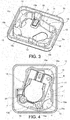
- the actuator indicated by 1, is shown in Figures 4 to 8 in the condition in which it is assembled to the support.
- the actuator 1 is an electric actuator.
- the actuator 1 is an actuator of a wholly conventional type, and comprises a casing 2, along the perimeter of which fastening areas 4 are arranged.
- a casing 2 along the perimeter of which fastening areas 4 are arranged.
- the casing 2 of the actuator 1 also has a body which is approximately rectangular in plan view.
- Conventional components such as an electric motor, a reduction gearbox, circuit components (not shown), and the like are housed inside the casing 2.
- the actuator 1 further comprises an output shaft 3 protruding externally from the casing 1, which is connected to the motor and to the reduction gearbox for operation, and is designed to drive a component (not shown) positioned within the heating, ventilation and/or air conditioning system.
- the output shaft of the actuator 1 extends perpendicularly to the bottom wall 12 of the seat 11, that is to say perpendicularly to the plane of Figures 4 to 6 , and parallel to the plane of Figures 7 and 8 .
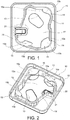
- Figures 1 to 3 show a support 10 designed to be assembled with the actuator 1.
- This support may, for example, be formed on a wall of a heating, ventilation and/or air conditioning system, or may consist of a separate element which is fastened to the aforesaid wall.
- the support 10 comprises a mounting seat 11 into which the actuator 1 can be fitted by axial insertion and subsequent rotation.
- the mounting seat 11 comprises a bottom wall 12 in which is formed an aperture 13, which is designed to allow the output shaft of the actuator 1 to be coupled to a component of the heating, ventilation and/or air conditioning system (not shown) positioned on the opposite side of the bottom wall 12 from the actuator 1.
- the mounting seat 11 further comprises a perimetral wall 14 arranged around the mounting seat 11.
- a plurality of stop members 15 are formed integrally with the perimetral wall 14. In the illustrated example, there are three of these stop members 15; in other words, the number of these members corresponds to the number of fastening areas 4 of the casing 2 of the actuator 1.
- the stop members 15 are formed so as to protrude from the bottom wall 12. Each of these stop members 15 is adapted to receive a corresponding fastening area 4 of the casing 2 of the actuator 1.
- Each stop member 15 comprises a perimetral wall extension 15a which extends axially from the bottom wall 12 and is laterally connected to the perimetral wall 14, and a projection 15b, spaced apart from the bottom wall 12, which is axially connected to the respective perimetral wall extension 15a and laterally connected to the perimetral wall 14.
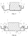
- Each projection 15b has an axial stop surface 15c (shown in Figure 8 ) facing towards the bottom wall 12 of the mounting seat 11 and designed to axially lock the casing 2 of the actuator 1.
- the mounting seat 11 has a mouth designed to allow the passage of the profile of the casing 2 of the actuator 1.
- the fastening device described herein further comprises at least one spring element 20 formed on the bottom wall 12 of the mounting seat 12.
- this spring element could be formed on the perimetral wall 14 of the mounting seat 12.
- the spring element 20 is formed as a tab which in its rest position protrudes in the axial direction with respect to the bottom wall 12 (see, in particular, Figure 7 ).
- the spring element 20 is positioned so as to define, by interaction with the perimetral wall 14 and the stop members 15, a locking position for the actuator 1.
- Figures 4 to 6 show different stages of movement during the assembly of the actuator 1 to the support 10.
- the actuator 1 is inserted in the axial direction (that is to say, perpendicularly to the plane of Figure 4 ).
- the casing 2 of the actuator 1 engages the spring element 20 which thus bends towards the bottom wall 12.
- the output shaft of the actuator 1 is inserted into the aperture 13 to allow it to be coupled to a component of the heating, ventilation and/or air conditioning system positioned on the opposite side of the bottom wall 12.
- the casing 2 of the actuator 1 is then rotated about an axis of rotation which is substantially coaxial with the output shaft of the actuator 1 ( Figure 5 ). During this rotation, the fastening areas 4 of the casing 2 of the actuator 1 become inserted into the respective stop members 15, in the gaps formed between the respective projections 15a and the bottom wall 12.
- the spring element 20 On completion of the rotation of the casing 2 of the actuator 1 ( Figure 6 ), the spring element 20 is released from engagement with the casing 2 and therefore springs into its rest position to rotationally lock the casing 2 of the actuator 1 between the spring element 20 and the perimetral wall 14 and/or the stop members 15 of the mounting seat 11 ( Figure 7 ).
- the casing 2 of the actuator 1 is retained not only by a free end 21 of the spring element 20 which acts as a stop for a side surface of the casing 2 of the actuator 1, but also by the three perimetral wall extensions 15a, each of which acts as a stop for a respective fastening area 4, and by a portion of perimetral wall 14 which acts as a stop for a fourth corner of the casing 2.
- the axial retention of the actuator 1 is provided by the axial stop surfaces 15c, each of which acts as a stop for a respective fastening area 4 ( Figure 8 ).
Landscapes
- Engineering & Computer Science (AREA)
- Mechanical Engineering (AREA)
- General Engineering & Computer Science (AREA)
- Physics & Mathematics (AREA)
- Thermal Sciences (AREA)
- Air-Conditioning For Vehicles (AREA)
- Motor Or Generator Frames (AREA)
Claims (3)
- Vorrichtung zur Befestigung eines Aktuators, insbesondere eines elektrischen Aktuators, an einem Träger, insbesondere an einer Wand eines Heizungs-, Ventilations- und/oder Klimaanlage-Systems, wobei die Vorrichtung aufweist:einen Aktuator (1) mit einem Gehäuse (2), entlang dessen Umfang eine Mehrzahl von Befestigungsbereichen (4) angeordnet ist, und der Aktuator weiter eine von dem Gehäuse (2) aus nach außen vorragende Antriebswelle (3) aufweist, undeinen Träger (10) mit einem Montagesitz (11), in den der Aktuator (1) durch axiales Einsetzen und sich daran anschließendes Drehen eingepasst werden kann, wobei der Montagesitz (11) eine Bodenwand (12) mit einer zum Einsetzen der Antriebswelle (3) des Aktuators vorgesehenen Öffnung (13) und eine Mehrzahl von von der Bodenwand (12) aus vorragenden Stoppelementen (15) aufweist, von denen jedes zur Aufnahme eines zugehörigen Befestigungsbereichs (4) des Gehäuses (2) des Aktuators (1) ausgestaltet ist und einen von der Bodenwand (12) des Montagesitzes (11) beabstandeten Vorsprung (15b) aufweist und eine der Bodenwand (12) des Montagesitzes (11) zugewandte axiale Stoppoberfläche (15c) aufweist, die zur axialen Arretierung des Gehäuses (2) des Aktuators (1) vorgesehen ist,wobei der Montagesitz (11) eine um den Montagesitz (11) herum angeordnete Umfangswand (14) aufweist, mit der die Stoppelemente (15) einstückig ausgebildet sind, jedes Stoppelement (15) weiter einen Umfangswandfortsatz (15a) aufweist, der sich axial von der Bodenwand (12) aus erstreckt und lateral mit der Umfangswand (14) verbunden ist, wobei jeder Vorsprung (15b) jeweils axial mit dem zugehörigen Umfangswandfortsatz (15a) und lateral mit der Umfangswand (14) verbunden ist, undwobei die Befestigungsvorrichtung weiter mindestens ein an der Bodenwand (12) und/oder an der Umfangswand (14) des Montagesitzes (11) ausgebildetes Federelement (20) aufweist, das Federelement (20) während des axialen Einsetzens des Aktuators (1) mit dem Gehäuse (2) des Aktuators (1) in Eingriff steht und am Ende der Drehung des Gehäuses (2) des Aktuators (1) federt, um das Gehäuse (2) des Aktuators (1) zwischen dem Federelement (20) und der Umfangswand (14) und/oder den Stoppelementen (15) des Montagesitzes (11) drehfest zu halten, wobeidas Gehäuse (2) des Aktuators (1) in einer Draufsicht einen ungefähr rechteckigen Körper mit vier Ecken aufweist, die Befestigungsbereiche (4) an drei der vier Ecken des Gehäuses (2) angeordnet sind, und die Zahl der Stoppelemente (15) drei beträgt, wobei wenn das Gehäuse (2) des Aktuators (1) drehfest gehalten wird, das Gehäuse einerseits durch das Federelement (20), das als ein Stopp für eine Seitenoberfläche des Gehäuses (2) des Aktuators (1) wirkt, und andererseits durch die Umfangswandfortsätze (15a) der Stoppelemente (15), von denen jeder als ein Stopp für einen zugehörigen Befestigungsbereich (4) wirkt, und durch einen Bereich der Umfangswand (14) gehalten wird, der als ein Stopp für eine vierte Ecke des Gehäuses (2) wirkt.
- Vorrichtung gemäß Anspruch 1, wobei das Federelement (20) als eine Lasche ausgebildet ist, die in ihrer Ruhelage bezüglich der Bodenwand (12) in der axialen Richtung vorragt.
- Vorrichtung gemäß Anspruch 2, wobei das Federelement (20) ein freies Ende (21) aufweist, das dazu ausgestaltet ist, als ein Stopp für eine Seitenoberfläche des Gehäuses (2) des Aktuators (1) zu wirken.
Applications Claiming Priority (1)
| Application Number | Priority Date | Filing Date | Title |
|---|---|---|---|
| ITUB2015A002557A ITUB20152557A1 (it) | 2015-07-28 | 2015-07-28 | Fissaggio senza viti di un attuatore in un’unità di climatizzazione. |
Publications (2)
| Publication Number | Publication Date |
|---|---|
| EP3124802A1 EP3124802A1 (de) | 2017-02-01 |
| EP3124802B1 true EP3124802B1 (de) | 2020-08-05 |
Family
ID=54329955
Family Applications (1)
| Application Number | Title | Priority Date | Filing Date |
|---|---|---|---|
| EP16180974.4A Active EP3124802B1 (de) | 2015-07-28 | 2016-07-25 | Schraubenlose befestigung eines aktuators in einer klimaanlageneinheit |
Country Status (3)
| Country | Link |
|---|---|
| EP (1) | EP3124802B1 (de) |
| ES (1) | ES2828957T3 (de) |
| IT (1) | ITUB20152557A1 (de) |
Family Cites Families (3)
| Publication number | Priority date | Publication date | Assignee | Title |
|---|---|---|---|---|
| IT227551Y1 (it) * | 1992-05-12 | 1997-12-15 | Veglia Borletti Srl | Dispositivo di assemblaggio di un quadrante di uno strumento di bordo di un veicolo con il relativo meccanismo di movimento dello strumento. |
| US5498130A (en) * | 1994-10-18 | 1996-03-12 | Itt Automotive Electrical Systems Inc. | Cooling fan mounting system |
| DE102004005028A1 (de) * | 2004-01-30 | 2005-09-01 | Behr Gmbh & Co. Kg | Befestigungsanordnung, Antriebsvorrichtung, Lüfterzarge und Wärmeübertrageranordnung |
-
2015
- 2015-07-28 IT ITUB2015A002557A patent/ITUB20152557A1/it unknown
-
2016
- 2016-07-25 EP EP16180974.4A patent/EP3124802B1/de active Active
- 2016-07-25 ES ES16180974T patent/ES2828957T3/es active Active
Non-Patent Citations (1)
| Title |
|---|
| None * |
Also Published As
| Publication number | Publication date |
|---|---|
| ITUB20152557A1 (it) | 2017-01-28 |
| ES2828957T3 (es) | 2021-05-28 |
| EP3124802A1 (de) | 2017-02-01 |
Similar Documents
| Publication | Publication Date | Title |
|---|---|---|
| US8888571B2 (en) | Fastening device for an actuator and a housing, in particular for a motor vehicle | |
| KR102248740B1 (ko) | 프로그레시브 기어를 갖춘 액츄에이터 | |
| CN104080692B (zh) | 机动车辆的前脸框架和支承致动器的支承件的组件 | |
| JP6449463B2 (ja) | ハウジングに対するモータの一体ロックを有する小型のアクチュエータ | |
| US5529282A (en) | Valve actuating device of a heating and/or cooling system | |
| CN113196622A (zh) | 阀、特别是膨胀阀 | |
| EP3199395A1 (de) | Verschlussvorrichtung für ein frontgitter eines fahrzeugs | |
| CN105899403A (zh) | 具有驱动装置的车辆座椅和用于以无游隙的方式附接驱动装置的方法 | |
| US9723748B2 (en) | Electronic module with removable fan assembly | |
| CN105370968A (zh) | 用于球心阀组件的无工具阀杆连接器组件 | |
| US20150044959A1 (en) | Vehicle air-conditioning device | |
| EP3124802B1 (de) | Schraubenlose befestigung eines aktuators in einer klimaanlageneinheit | |
| KR102681681B1 (ko) | Hvac 시스템의 기류 방향 제어 요소의 위치 유지 방법 | |
| EP3471977B1 (de) | Anordnung und verfahren zur befestigung und zum ersetzen eines steuerungsmotors in einem fahrzeugheizungs-, -lüftungs- und/oder klimatisierungssystem | |
| US20190170452A1 (en) | Heating or air conditioning system | |
| EP3638916B1 (de) | Hybridvorrichtung zur steuerung der drehung eines lüfters zur kühlung der kühlflüssigkeit eines fahrzeugs | |
| US11958335B2 (en) | Electric actuator for a motor vehicle heating, ventilation and/or air conditioning system | |
| EP3124807A1 (de) | Betätigungsvorrichtung zum öffnen und/oder schliessen einer fahrzeugtür | |
| KR100932627B1 (ko) | 차량의 공조장치용 캠과 액츄에이터 결합구조 | |
| CN107921840B (zh) | 外壳单元 | |
| KR102065969B1 (ko) | 축 유지 수단 | |
| CN111819094A (zh) | Hvac模块 | |
| KR102116736B1 (ko) | 피드백 센서 및 피드백 센서를 구비한 액츄에이터 | |
| US20240159312A1 (en) | Actuator, and Device for Engaging a Park Lock of a Motor-Vehicle Automatic Transmission Having Such an Actuator, and Motor Vehicle Equipped Therewith | |
| AU2024369029A1 (en) | Actuating drive with an axially displaceable drive sleeve |
Legal Events
| Date | Code | Title | Description |
|---|---|---|---|
| PUAI | Public reference made under article 153(3) epc to a published international application that has entered the european phase |
Free format text: ORIGINAL CODE: 0009012 |
|
| STAA | Information on the status of an ep patent application or granted ep patent |
Free format text: STATUS: THE APPLICATION HAS BEEN PUBLISHED |
|
| AK | Designated contracting states |
Kind code of ref document: A1 Designated state(s): AL AT BE BG CH CY CZ DE DK EE ES FI FR GB GR HR HU IE IS IT LI LT LU LV MC MK MT NL NO PL PT RO RS SE SI SK SM TR |
|
| AX | Request for extension of the european patent |
Extension state: BA ME |
|
| STAA | Information on the status of an ep patent application or granted ep patent |
Free format text: STATUS: REQUEST FOR EXAMINATION WAS MADE |
|
| 17P | Request for examination filed |
Effective date: 20170727 |
|
| RBV | Designated contracting states (corrected) |
Designated state(s): AL AT BE BG CH CY CZ DE DK EE ES FI FR GB GR HR HU IE IS IT LI LT LU LV MC MK MT NL NO PL PT RO RS SE SI SK SM TR |
|
| STAA | Information on the status of an ep patent application or granted ep patent |
Free format text: STATUS: EXAMINATION IS IN PROGRESS |
|
| 17Q | First examination report despatched |
Effective date: 20190619 |
|
| GRAP | Despatch of communication of intention to grant a patent |
Free format text: ORIGINAL CODE: EPIDOSNIGR1 |
|
| STAA | Information on the status of an ep patent application or granted ep patent |
Free format text: STATUS: GRANT OF PATENT IS INTENDED |
|
| RIC1 | Information provided on ipc code assigned before grant |
Ipc: F16B 5/10 20060101AFI20200121BHEP Ipc: B60H 1/00 20060101ALN20200121BHEP |
|
| INTG | Intention to grant announced |
Effective date: 20200212 |
|
| GRAS | Grant fee paid |
Free format text: ORIGINAL CODE: EPIDOSNIGR3 |
|
| GRAA | (expected) grant |
Free format text: ORIGINAL CODE: 0009210 |
|
| STAA | Information on the status of an ep patent application or granted ep patent |
Free format text: STATUS: THE PATENT HAS BEEN GRANTED |
|
| AK | Designated contracting states |
Kind code of ref document: B1 Designated state(s): AL AT BE BG CH CY CZ DE DK EE ES FI FR GB GR HR HU IE IS IT LI LT LU LV MC MK MT NL NO PL PT RO RS SE SI SK SM TR |
|
| REG | Reference to a national code |
Ref country code: GB Ref legal event code: FG4D |
|
| REG | Reference to a national code |
Ref country code: CH Ref legal event code: EP |
|
| REG | Reference to a national code |
Ref country code: AT Ref legal event code: REF Ref document number: 1299102 Country of ref document: AT Kind code of ref document: T Effective date: 20200815 |
|
| REG | Reference to a national code |
Ref country code: DE Ref legal event code: R096 Ref document number: 602016041220 Country of ref document: DE |
|
| REG | Reference to a national code |
Ref country code: IE Ref legal event code: FG4D |
|
| REG | Reference to a national code |
Ref country code: LT Ref legal event code: MG4D |
|
| REG | Reference to a national code |
Ref country code: NL Ref legal event code: MP Effective date: 20200805 |
|
| REG | Reference to a national code |
Ref country code: AT Ref legal event code: MK05 Ref document number: 1299102 Country of ref document: AT Kind code of ref document: T Effective date: 20200805 |
|
| PG25 | Lapsed in a contracting state [announced via postgrant information from national office to epo] |
Ref country code: GR Free format text: LAPSE BECAUSE OF FAILURE TO SUBMIT A TRANSLATION OF THE DESCRIPTION OR TO PAY THE FEE WITHIN THE PRESCRIBED TIME-LIMIT Effective date: 20201106 Ref country code: BG Free format text: LAPSE BECAUSE OF FAILURE TO SUBMIT A TRANSLATION OF THE DESCRIPTION OR TO PAY THE FEE WITHIN THE PRESCRIBED TIME-LIMIT Effective date: 20201105 Ref country code: NO Free format text: LAPSE BECAUSE OF FAILURE TO SUBMIT A TRANSLATION OF THE DESCRIPTION OR TO PAY THE FEE WITHIN THE PRESCRIBED TIME-LIMIT Effective date: 20201105 Ref country code: AT Free format text: LAPSE BECAUSE OF FAILURE TO SUBMIT A TRANSLATION OF THE DESCRIPTION OR TO PAY THE FEE WITHIN THE PRESCRIBED TIME-LIMIT Effective date: 20200805 Ref country code: HR Free format text: LAPSE BECAUSE OF FAILURE TO SUBMIT A TRANSLATION OF THE DESCRIPTION OR TO PAY THE FEE WITHIN THE PRESCRIBED TIME-LIMIT Effective date: 20200805 Ref country code: FI Free format text: LAPSE BECAUSE OF FAILURE TO SUBMIT A TRANSLATION OF THE DESCRIPTION OR TO PAY THE FEE WITHIN THE PRESCRIBED TIME-LIMIT Effective date: 20200805 Ref country code: LT Free format text: LAPSE BECAUSE OF FAILURE TO SUBMIT A TRANSLATION OF THE DESCRIPTION OR TO PAY THE FEE WITHIN THE PRESCRIBED TIME-LIMIT Effective date: 20200805 Ref country code: SE Free format text: LAPSE BECAUSE OF FAILURE TO SUBMIT A TRANSLATION OF THE DESCRIPTION OR TO PAY THE FEE WITHIN THE PRESCRIBED TIME-LIMIT Effective date: 20200805 Ref country code: PT Free format text: LAPSE BECAUSE OF FAILURE TO SUBMIT A TRANSLATION OF THE DESCRIPTION OR TO PAY THE FEE WITHIN THE PRESCRIBED TIME-LIMIT Effective date: 20201207 |
|
| PG25 | Lapsed in a contracting state [announced via postgrant information from national office to epo] |
Ref country code: LV Free format text: LAPSE BECAUSE OF FAILURE TO SUBMIT A TRANSLATION OF THE DESCRIPTION OR TO PAY THE FEE WITHIN THE PRESCRIBED TIME-LIMIT Effective date: 20200805 Ref country code: NL Free format text: LAPSE BECAUSE OF FAILURE TO SUBMIT A TRANSLATION OF THE DESCRIPTION OR TO PAY THE FEE WITHIN THE PRESCRIBED TIME-LIMIT Effective date: 20200805 Ref country code: PL Free format text: LAPSE BECAUSE OF FAILURE TO SUBMIT A TRANSLATION OF THE DESCRIPTION OR TO PAY THE FEE WITHIN THE PRESCRIBED TIME-LIMIT Effective date: 20200805 Ref country code: RS Free format text: LAPSE BECAUSE OF FAILURE TO SUBMIT A TRANSLATION OF THE DESCRIPTION OR TO PAY THE FEE WITHIN THE PRESCRIBED TIME-LIMIT Effective date: 20200805 Ref country code: IS Free format text: LAPSE BECAUSE OF FAILURE TO SUBMIT A TRANSLATION OF THE DESCRIPTION OR TO PAY THE FEE WITHIN THE PRESCRIBED TIME-LIMIT Effective date: 20201205 |
|
| PG25 | Lapsed in a contracting state [announced via postgrant information from national office to epo] |
Ref country code: EE Free format text: LAPSE BECAUSE OF FAILURE TO SUBMIT A TRANSLATION OF THE DESCRIPTION OR TO PAY THE FEE WITHIN THE PRESCRIBED TIME-LIMIT Effective date: 20200805 Ref country code: SM Free format text: LAPSE BECAUSE OF FAILURE TO SUBMIT A TRANSLATION OF THE DESCRIPTION OR TO PAY THE FEE WITHIN THE PRESCRIBED TIME-LIMIT Effective date: 20200805 Ref country code: RO Free format text: LAPSE BECAUSE OF FAILURE TO SUBMIT A TRANSLATION OF THE DESCRIPTION OR TO PAY THE FEE WITHIN THE PRESCRIBED TIME-LIMIT Effective date: 20200805 Ref country code: DK Free format text: LAPSE BECAUSE OF FAILURE TO SUBMIT A TRANSLATION OF THE DESCRIPTION OR TO PAY THE FEE WITHIN THE PRESCRIBED TIME-LIMIT Effective date: 20200805 Ref country code: CZ Free format text: LAPSE BECAUSE OF FAILURE TO SUBMIT A TRANSLATION OF THE DESCRIPTION OR TO PAY THE FEE WITHIN THE PRESCRIBED TIME-LIMIT Effective date: 20200805 |
|
| REG | Reference to a national code |
Ref country code: DE Ref legal event code: R097 Ref document number: 602016041220 Country of ref document: DE |
|
| REG | Reference to a national code |
Ref country code: ES Ref legal event code: FG2A Ref document number: 2828957 Country of ref document: ES Kind code of ref document: T3 Effective date: 20210528 |
|
| PG25 | Lapsed in a contracting state [announced via postgrant information from national office to epo] |
Ref country code: AL Free format text: LAPSE BECAUSE OF FAILURE TO SUBMIT A TRANSLATION OF THE DESCRIPTION OR TO PAY THE FEE WITHIN THE PRESCRIBED TIME-LIMIT Effective date: 20200805 |
|
| PLBE | No opposition filed within time limit |
Free format text: ORIGINAL CODE: 0009261 |
|
| STAA | Information on the status of an ep patent application or granted ep patent |
Free format text: STATUS: NO OPPOSITION FILED WITHIN TIME LIMIT |
|
| PG25 | Lapsed in a contracting state [announced via postgrant information from national office to epo] |
Ref country code: SK Free format text: LAPSE BECAUSE OF FAILURE TO SUBMIT A TRANSLATION OF THE DESCRIPTION OR TO PAY THE FEE WITHIN THE PRESCRIBED TIME-LIMIT Effective date: 20200805 |
|
| 26N | No opposition filed |
Effective date: 20210507 |
|
| PG25 | Lapsed in a contracting state [announced via postgrant information from national office to epo] |
Ref country code: IT Free format text: LAPSE BECAUSE OF FAILURE TO SUBMIT A TRANSLATION OF THE DESCRIPTION OR TO PAY THE FEE WITHIN THE PRESCRIBED TIME-LIMIT Effective date: 20200805 |
|
| PG25 | Lapsed in a contracting state [announced via postgrant information from national office to epo] |
Ref country code: SI Free format text: LAPSE BECAUSE OF FAILURE TO SUBMIT A TRANSLATION OF THE DESCRIPTION OR TO PAY THE FEE WITHIN THE PRESCRIBED TIME-LIMIT Effective date: 20200805 |
|
| REG | Reference to a national code |
Ref country code: CH Ref legal event code: PL |
|
| GBPC | Gb: european patent ceased through non-payment of renewal fee |
Effective date: 20210725 |
|
| PG25 | Lapsed in a contracting state [announced via postgrant information from national office to epo] |
Ref country code: MC Free format text: LAPSE BECAUSE OF FAILURE TO SUBMIT A TRANSLATION OF THE DESCRIPTION OR TO PAY THE FEE WITHIN THE PRESCRIBED TIME-LIMIT Effective date: 20200805 |
|
| REG | Reference to a national code |
Ref country code: BE Ref legal event code: MM Effective date: 20210731 |
|
| PG25 | Lapsed in a contracting state [announced via postgrant information from national office to epo] |
Ref country code: LI Free format text: LAPSE BECAUSE OF NON-PAYMENT OF DUE FEES Effective date: 20210731 Ref country code: GB Free format text: LAPSE BECAUSE OF NON-PAYMENT OF DUE FEES Effective date: 20210725 Ref country code: CH Free format text: LAPSE BECAUSE OF NON-PAYMENT OF DUE FEES Effective date: 20210731 |
|
| PG25 | Lapsed in a contracting state [announced via postgrant information from national office to epo] |
Ref country code: LU Free format text: LAPSE BECAUSE OF NON-PAYMENT OF DUE FEES Effective date: 20210725 |
|
| PG25 | Lapsed in a contracting state [announced via postgrant information from national office to epo] |
Ref country code: IE Free format text: LAPSE BECAUSE OF NON-PAYMENT OF DUE FEES Effective date: 20210725 Ref country code: BE Free format text: LAPSE BECAUSE OF NON-PAYMENT OF DUE FEES Effective date: 20210731 |
|
| PG25 | Lapsed in a contracting state [announced via postgrant information from national office to epo] |
Ref country code: HU Free format text: LAPSE BECAUSE OF FAILURE TO SUBMIT A TRANSLATION OF THE DESCRIPTION OR TO PAY THE FEE WITHIN THE PRESCRIBED TIME-LIMIT; INVALID AB INITIO Effective date: 20160725 |
|
| PG25 | Lapsed in a contracting state [announced via postgrant information from national office to epo] |
Ref country code: CY Free format text: LAPSE BECAUSE OF FAILURE TO SUBMIT A TRANSLATION OF THE DESCRIPTION OR TO PAY THE FEE WITHIN THE PRESCRIBED TIME-LIMIT Effective date: 20200805 |
|
| PG25 | Lapsed in a contracting state [announced via postgrant information from national office to epo] |
Ref country code: MK Free format text: LAPSE BECAUSE OF FAILURE TO SUBMIT A TRANSLATION OF THE DESCRIPTION OR TO PAY THE FEE WITHIN THE PRESCRIBED TIME-LIMIT Effective date: 20200805 |
|
| PG25 | Lapsed in a contracting state [announced via postgrant information from national office to epo] |
Ref country code: TR Free format text: LAPSE BECAUSE OF FAILURE TO SUBMIT A TRANSLATION OF THE DESCRIPTION OR TO PAY THE FEE WITHIN THE PRESCRIBED TIME-LIMIT Effective date: 20200805 |
|
| PG25 | Lapsed in a contracting state [announced via postgrant information from national office to epo] |
Ref country code: MT Free format text: LAPSE BECAUSE OF FAILURE TO SUBMIT A TRANSLATION OF THE DESCRIPTION OR TO PAY THE FEE WITHIN THE PRESCRIBED TIME-LIMIT Effective date: 20200805 |
|
| PGFP | Annual fee paid to national office [announced via postgrant information from national office to epo] |
Ref country code: FR Payment date: 20250630 Year of fee payment: 10 |
|
| PGFP | Annual fee paid to national office [announced via postgrant information from national office to epo] |
Ref country code: ES Payment date: 20250801 Year of fee payment: 10 |
|
| PGFP | Annual fee paid to national office [announced via postgrant information from national office to epo] |
Ref country code: DE Payment date: 20250725 Year of fee payment: 10 |