EP3124809B1 - Dämpfender drehschaftmechanismus mit automatischer kompensation - Google Patents
Dämpfender drehschaftmechanismus mit automatischer kompensation Download PDFInfo
- Publication number
- EP3124809B1 EP3124809B1 EP15767895.4A EP15767895A EP3124809B1 EP 3124809 B1 EP3124809 B1 EP 3124809B1 EP 15767895 A EP15767895 A EP 15767895A EP 3124809 B1 EP3124809 B1 EP 3124809B1
- Authority
- EP
- European Patent Office
- Prior art keywords
- sleeve
- chamber body
- spindle
- disposed
- passage
- Prior art date
- Legal status (The legal status is an assumption and is not a legal conclusion. Google has not performed a legal analysis and makes no representation as to the accuracy of the status listed.)
- Active
Links
Images






Classifications
-
- F—MECHANICAL ENGINEERING; LIGHTING; HEATING; WEAPONS; BLASTING
- F16—ENGINEERING ELEMENTS AND UNITS; GENERAL MEASURES FOR PRODUCING AND MAINTAINING EFFECTIVE FUNCTIONING OF MACHINES OR INSTALLATIONS; THERMAL INSULATION IN GENERAL
- F16F—SPRINGS; SHOCK-ABSORBERS; MEANS FOR DAMPING VIBRATION
- F16F9/00—Springs, vibration-dampers, shock-absorbers, or similarly-constructed movement-dampers using a fluid or the equivalent as damping medium
- F16F9/32—Details
- F16F9/50—Special means providing automatic damping adjustment, i.e. self-adjustment of damping by particular sliding movements of a valve element, other than flexions or displacement of valve discs; Special means providing self-adjustment of spring characteristics
-
- E—FIXED CONSTRUCTIONS
- E05—LOCKS; KEYS; WINDOW OR DOOR FITTINGS; SAFES
- E05F—DEVICES FOR MOVING WINGS INTO OPEN OR CLOSED POSITION; CHECKS FOR WINGS; WING FITTINGS NOT OTHERWISE PROVIDED FOR, CONCERNED WITH THE FUNCTIONING OF THE WING
- E05F3/00—Closers or openers with braking devices, e.g. checks; Construction of pneumatic or liquid braking devices
- E05F3/04—Closers or openers with braking devices, e.g. checks; Construction of pneumatic or liquid braking devices with liquid piston brakes
-
- E—FIXED CONSTRUCTIONS
- E05—LOCKS; KEYS; WINDOW OR DOOR FITTINGS; SAFES
- E05F—DEVICES FOR MOVING WINGS INTO OPEN OR CLOSED POSITION; CHECKS FOR WINGS; WING FITTINGS NOT OTHERWISE PROVIDED FOR, CONCERNED WITH THE FUNCTIONING OF THE WING
- E05F3/00—Closers or openers with braking devices, e.g. checks; Construction of pneumatic or liquid braking devices
- E05F3/20—Closers or openers with braking devices, e.g. checks; Construction of pneumatic or liquid braking devices in hinges
-
- F—MECHANICAL ENGINEERING; LIGHTING; HEATING; WEAPONS; BLASTING
- F16—ENGINEERING ELEMENTS AND UNITS; GENERAL MEASURES FOR PRODUCING AND MAINTAINING EFFECTIVE FUNCTIONING OF MACHINES OR INSTALLATIONS; THERMAL INSULATION IN GENERAL
- F16F—SPRINGS; SHOCK-ABSORBERS; MEANS FOR DAMPING VIBRATION
- F16F9/00—Springs, vibration-dampers, shock-absorbers, or similarly-constructed movement-dampers using a fluid or the equivalent as damping medium
- F16F9/10—Springs, vibration-dampers, shock-absorbers, or similarly-constructed movement-dampers using a fluid or the equivalent as damping medium using liquid only; using a fluid of which the nature is immaterial
- F16F9/14—Devices with one or more members, e.g. pistons, vanes, moving to and fro in chambers and using throttling effect
- F16F9/16—Devices with one or more members, e.g. pistons, vanes, moving to and fro in chambers and using throttling effect involving only straight-line movement of the effective parts
-
- F—MECHANICAL ENGINEERING; LIGHTING; HEATING; WEAPONS; BLASTING
- F16—ENGINEERING ELEMENTS AND UNITS; GENERAL MEASURES FOR PRODUCING AND MAINTAINING EFFECTIVE FUNCTIONING OF MACHINES OR INSTALLATIONS; THERMAL INSULATION IN GENERAL
- F16F—SPRINGS; SHOCK-ABSORBERS; MEANS FOR DAMPING VIBRATION
- F16F9/00—Springs, vibration-dampers, shock-absorbers, or similarly-constructed movement-dampers using a fluid or the equivalent as damping medium
- F16F9/32—Details
- F16F9/50—Special means providing automatic damping adjustment, i.e. self-adjustment of damping by particular sliding movements of a valve element, other than flexions or displacement of valve discs; Special means providing self-adjustment of spring characteristics
- F16F9/516—Special means providing automatic damping adjustment, i.e. self-adjustment of damping by particular sliding movements of a valve element, other than flexions or displacement of valve discs; Special means providing self-adjustment of spring characteristics resulting in the damping effects during contraction being different from the damping effects during extension, i.e. responsive to the direction of movement
-
- A—HUMAN NECESSITIES
- A47—FURNITURE; DOMESTIC ARTICLES OR APPLIANCES; COFFEE MILLS; SPICE MILLS; SUCTION CLEANERS IN GENERAL
- A47K—SANITARY EQUIPMENT; ACCESSORIES THEREFOR, e.g. TOILET ACCESSORIES
- A47K13/00—Seats or covers for all kinds of closets
- A47K13/12—Hinges
-
- E—FIXED CONSTRUCTIONS
- E05—LOCKS; KEYS; WINDOW OR DOOR FITTINGS; SAFES
- E05Y—INDEXING SCHEME ASSOCIATED WITH SUBCLASSES E05D AND E05F, RELATING TO CONSTRUCTION ELEMENTS, ELECTRIC CONTROL, POWER SUPPLY, POWER SIGNAL OR TRANSMISSION, USER INTERFACES, MOUNTING OR COUPLING, DETAILS, ACCESSORIES, AUXILIARY OPERATIONS NOT OTHERWISE PROVIDED FOR, APPLICATION THEREOF
- E05Y2999/00—Subject-matter not otherwise provided for in this subclass
-
- F—MECHANICAL ENGINEERING; LIGHTING; HEATING; WEAPONS; BLASTING
- F16—ENGINEERING ELEMENTS AND UNITS; GENERAL MEASURES FOR PRODUCING AND MAINTAINING EFFECTIVE FUNCTIONING OF MACHINES OR INSTALLATIONS; THERMAL INSULATION IN GENERAL
- F16F—SPRINGS; SHOCK-ABSORBERS; MEANS FOR DAMPING VIBRATION
- F16F2232/00—Nature of movement
- F16F2232/04—Rotary-to-translation conversion
Definitions
- the present invention relates to a damping spindle mechanism, especially to a damping spindle mechanism that can rotate easily in a direction and be damped to rotate in the reverse direction with self compensation function.
- Rotation connectors are widely used in varies fields, for example, they can be used in toilet seat cover, fridge door, telephone flip cover and cabinet door, etc, when used in toilet seat cover, the rotation connector connects the toilet seat cover and the toilet main body, there is no resistance when the toilet seat cover is flipped up or put down, it may causes that the toilet seat cover punches the toilet main body so hard when the user puts the toilet seat cover down, therefore, it easily damages the connecting portion of the toilet seat cover and the main body, on the other hand, it may also damage the toilet seat cover or the main body.
- the damping spindle mechanism uses blade to serve as a check valve, when the damping spindle mechanism is applied in the toilet seat cover, the toilet seat cover is assembled to the main body by the damping spindle mechanism, when the rotating shaft rotates in a direction, the blade closes the main passage of the damping oil, the damping oil can just flow through the clearance between two chamber bodies, therefore, the damping oil flows slowly from one chamber body to the other chamber body, so that the seat cover drops down slowly, when the rotating shaft rotates to the opposite direction, the blade doesn't close the main passage of the damping oil, the damping oil flows through the main passage and the gap between the components, therefore, the damping oil flows quickly from the other chamber body to the chamber body, the seat cover is open quickly.
- the object of the present invention is to overcome the disadvantages of the existing known technology and to provide with a damping spindle mechanism with self compensation, with the self compensation, when the gap between the components is enlarged, it can automatically compensate the gap due to mechanical wear, thus making the damping spindle mechanism keep in a stable state in long period so as to lengthen the service life of the damping spindle mechanism.
- a damping spindle mechanism with self compensation comprising a spindle, a sleeve, a housing and a blade; the sleeve is coupled to the spindle in thread way; an anti-rotation structure is disposed between the sleeve and the housing, when the spindle rotates, the sleeve moves forward and backward along the axis of the spindle in the housing; the housing is disposed with a chamber, one section of the spindle threaded with the sleeve is assembled in the chamber of the housing to form a closed chamber; the close chamber is filled with damping oil and is separated to a first chamber body and a second chamber body by the sleeve; the sleeve is disposed with a first passage connecting the two chamber bodies in the axial direction; wherein the blade is of ring shape or arc shape coupled to the internal wall surface of the housing, the blade is disposed with a deformable first thin wall, when the blade
- the internal wall of the sleeve is coupled to the external wall of the spindle, the internal wall of one end of the sleeve near the second chamber body is disposed with a second thin wall of deformation, when the sleeve moves towards the second chamber body, the thin wall deforms towards the external wall surface of the spindle.
- the blade is disposed with a first cavity adjacent to the first thin wall, the recess of the first cavity of the blade is faced to the second chamber body, so that when the blade moves towards the second chamber body, the recess of the first cavity opens the first thin wall outwards under the action of the damping oil.
- the sleeve is disposed with a second cavity adjacent to the second thin wall, the recess of the second cavity of the sleeve is faced to the second chamber body, so that when the sleeve moves towards the second chamber body, the recess of the second cavity opens the second thin wall outwards under the action of the damping oil.
- An oil passage is disposed in the blade or between the blade and the sleeve.
- the blade comprises at least two arc single bodies, the single bodies surrounds to a circle or the single bodies and the convex body of the sleeve surround to a circle so as to couple to the internal wall surface of the housing in a ring shape.
- the section of the single body is V shaped, U shaped, E shaped, T shaped, W shaped or C shaped.
- the oil passage is a first through hole disposed in the blade along the axial direction.
- the oil passage is disposed between the blade and the sleeve, the oil passage comprises a gap disposed at one single body of the blade and a first groove disposed at the sleeve corresponding to the gap.
- the oil passage is disposed between the blade and the sleeve, the oil passage comprises a through groove once formed at the at least one end of the single body of the blade and a fitting surface of the convex body of the sleeve, the fitting surface is an incline surface.
- the first passage is a second groove once formed at the external wall of the sleeve in the axial direction of the spindle.
- the first passage is a second through hole disposed at the sleeve in the axial direction of the spindle.
- the anti-rotation structure comprises a first rib disposed at the external wall of the sleeve in the axial direction and a second rib disposed at the internal wall of the housing in the axial direction, the first rib and the second rib are mismatched.
- a second passage is disposed between the first chamber body and the second chamber body to connect the two chamber bodies, the section of the second passage is reducing, so that the flow constant of the damping oil in the second passage changes.
- the second passage is disposed between the sleeve and the spindle.
- the spindle is disposed with a central spindle with reducing internal diameter, the internal diameter reducing central spindle and the sleeve surround to form the second passage, the internal diameter of the central spindle with reducing internal diameter is gradually increased from the end near the first chamber body to the other end near the second chamber body; or in other case, the spindle is disposed with a central spindle with saltation internal diameter, the central spindle with saltation internal diameter and the sleeve surround to from the second passage, the internal diameter of the central spindle with saltation internal diameter is suddenly increased from the end near the first chamber body to the other end near the second chamber body.
- the central spindle of the spindle is disposed with a gradually changing first slot in the axial direction, the gradually changing first slot and the sleeve surround to form the second passage, the gradually changing first slot is gradually narrowed from the end near the first chamber body to the other end near the second chamber body; or in other case, the central spindle of the spindle is a gradient second slot in the axial direction, the gradient second slot and the sleeve surround to form the second passage, the gradient second slot is gradiently narrowed from the end near the first chamber body to the other end near the second chamber body.
- the external thread of the spindle is disposed with gradually changing third slot in the thread direction, the gradually changing third slot and the sleeve surround to form the second passage, the gradually changing third slot is gradually narrowed in screw way from the end near the first chamber body to the other end near the second chamber body.
- the second passage is disposed between the sleeve and the housing.
- the housing is disposed with a chamber body with internal diameter gradually changing, the chamber wall of the chamber body with internal diameter gradually changing and the sleeve surround to form the second passage, the internal diameter of the chamber body with internal diameter gradually changing is gradually narrowed from the end near the first chamber body to the other end near the second chamber body; or in other case, the housing is disposed with a chamber body with saltation internal diameter, the chamber wall of the chamber body with saltation internal diameter and the sleeve surround to form the second passage, the internal diameter of the chamber body with saltation internal diameter is suddenly decreased from the end near the first chamber body to the other end near the second chamber body.
- the chamber wall of the chamber body of the housing is disposed with a gradually changing fourth slot in the axial direction, the gradually changing fourth slot and the sleeve surround to form the second passage, the gradually changing fourth slot is gradually narrowed from the end near the first chamber body to the other end near the second chamber body; or in other case, the chamber wall of the chamber body of the housing is disposed with a gradient fifth slot in the axial direction, the gradient fifth slot and the sleeve surround to form the second passage, the gradient fifth slot is gradiently narrowed from the end near the first chamber to the other end near the second chamber body.
- the damping spindle mechanism with self compensation of the present invention plays self compensation via disposing thin walls structure in the sleeve and the blade, the thin walls of the blade and the sleeve are respectively coupled to the coupling surface of the housing and the spindle, under the action of pressure, the thin walls deforms slightly.
- the spindle drives the sleeve and the blade to move forth and back by the screw mechanism, in damping state, the spindle rotates in a direction to drive the sleeve to move towards the second chamber body, the space of the second chamber body is gradually decreased, the pressure of the damping oil of the second chamber body is increased, at the same time, the space of the first chamber body is gradually increased, the pressure of the damping oil in the first chamber body is decreased, due to the pressure difference, the damping oil in the second chamber body moves to the first chamber body, the moving chamber body pushes the blade to the first passage, the blade closes the first passage, on the other hand, the damping oil with increasing oil pressure moves to the first cavity, the recess of the first cavity makes the first thin wall expanding outwardly under the action of the damping oil pressure, so that the first thin wall deforms towards the internal wall surface of the housing, so as to compensate the gap between the blade and the housing due to mechanical wear after long period, at the same way, the damping oil with increasing oil pressure moves
- the sleeve moves towards the first chamber body, the space in the first chamber body is gradually decreased, the pressure of the damping oil in the first chamber body is increased, at the same time, the space of the second chamber body is gradually increased, the pressure of the damping oil in the second chamber body is decreased, due to the pressure difference, the damping oil of the first chamber body moves to the second chamber body, the moving damping oil pushes the blade away from the first passage, the first passage is open, the damping oil decompresses quickly, that is to say, the damping oil moves quickly from the first chamber body to the second chamber body, meanwhile, as the pressure of the damping oil of the first cavity and the second cavity is low, the self compensation structure doesn't act, therefore, no damping exists when the spindle rotates in the opposite direction.
- the blade moves forth and back at the sleeve, it serves as a check valve.
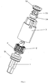
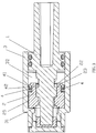
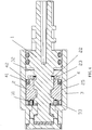
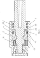
- the damping spindle mechanism with self compensation of the present invention comprises a spindle 1, a sleeve 2, a housing 3 and a blade 4; the sleeve 2 is coupled to the spindle 1 in thread way, that is to say, the spindle 1 is disposed with an external thread 11, the sleeve 2 is disposed with an internal thread 21; the housing 3 is disposed with a chamber, one section of the spindle 1 threaded to the sleeve 2 is assembled in the chamber of the housing and making the chamber a closed chamber, one end of the spindle 1 is inserted to the chamber of the housing 3, t a welding cover 52, a fixing block 53 and a fixing element 54 are used to support the end of the spindle 1 and also used to close one end of the chamber, the other end of the chamber is closed by a sealing ring 51, making the chamber of the housing a closed internal chamber; an anti-rotation structure is disposed between the sleeve 2 and the
- the internal wall of the sleeve 2 is coupled to the external wall of the spindle 1, the internal wall of the end of the sleeve 2 near the second chamber body is disposed with a deformable second thin wall 22, when the sleeve 2 moves towards the second chamber body 32, the second thin wall 22 deforms towards the external wall surface of the spindle 1.
- the blade 4 is disposed with a first cavity 42 adjacent to the first thin wall 41 , the recess of the first cavity 42 of the blade 4 is faced to the second chamber body, so that when the blade 4 moves towards the second chamber body, the recess of the first cavity opens the first thin wall 41 outwards under the action of the damping oil.
- the sleeve is disposed with a second cavity 23 adjacent to the second thin wall 22, the recess of the second cavity 23 of the sleeve is faced to the second chamber body, so that when the sleeve 2 moves towards the second chamber body, the recess of the second cavity 23 opens the second thin wall 22 outwards under the action of the damping oil.
- An oil passage is disposed in the blade or between the blade and the sleeve.
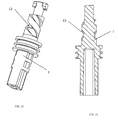
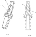
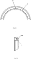
- the blade comprises two arc single bodies 40, the single bodies 40 surrounds to a circle, same as this embodiment, the sleeve 2 is disposed with two convex bodies 24, the two arc single bodies 40 and the two convex body 24 of the sleeve 2 surround to a circle so as to couple to the internal wall surface of the housing in a ring shape.
- the section of the single body is V shaped, as needed, it can be also U shaped, E shaped, T shaped, W shaped or C shaped, or it can be an integral whole.
- the oil passage is disposed between the blade 4 and the sleeve 2, the oil passage comprises a through groove 43 once formed at the at least one end of the single body of the blade and a fitting surface 241 of the convex body 24 of the sleeve, the fitting surface 241 is an incline surface.
- the first passage is a second groove 25 once formed at the external wall of the sleeve in the axial direction of the spindle.
- the anti-rotation structure comprises a first rib 26 disposed at the external wall of the sleeve in the axial direction and a second rib 33 disposed at the internal wall of the housing in the axial direction, the first rib 26 and the second rib 33 are mismatched.
- a second passage is disposed between the first chamber body 31 and the second chamber body 32 to connect the two chamber bodies, the section of the second passage is reducing, so that the flow constant of the damping oil in the second passage changes.
- the second passage is disposed between the sleeve and the spindle.
- the spindle 1 is disposed with a central spindle 12 with reducing internal diameter, the internal diameter reducing central spindle 12 and the sleeve 2 surround to form the second passage, the internal diameter of the central spindle 12 with reducing internal diameter is gradually increased from the end near the first chamber body to the other end near the second chamber body.
- the damping spindle mechanism with self compensation of the present invention is assembled between the toilet seat cover and the base 57, the toilet seat cover comprises a seatring 55 and an upper cover 56, the housing 3 of the present invention is fixed to the base 57, the spindle 1 of the present invention is fixed to the toilet seat cover.
- the damping spindle mechanism with self compensation of the present invention plays self compensation via disposing thin walls structure in the sleeve 2 and the blade 4, the thin walls of the blade 4 and the sleeve 2 are respectively coupled to the coupling surface of the housing and the spindle 1, under the action of pressure, the thin walls deforms slightly.
- the spindle 1 When the spindle 1 rotates, the spindle 1 drives the sleeve 2 and the blade 4 to move forth and back by the screw mechanism, in dropping slowly state, the spindle 1 rotates in a direction to drive the sleeve 2 to move towards the second chamber body 32, the space of the second chamber body 32 is gradually decreased, the pressure of the damping oil of the second chamber body 32 is increased, at the same time, the space of the first chamber body 31 is gradually increased, the pressure of the damping oil in the first chamber body 31 is decreased, due to the pressure difference, the damping oil in the second chamber body 32 moves to the first chamber body 31, the moving chamber body pushes the blade 4 to the first passage (the port of one end of the second groove 25), the blade 4 closes the first passage, on the other hand, the damping oil with increasing oil pressure moves to the first cavity 42, the recess of the first cavity 42 makes the first thin wall 41 expanding outwardly under the action of the damping oil pressure, so that the first thin wall 41 deforms towards
- the sleeve 2 moves towards the first chamber body 31, the space in the first chamber body 31 is gradually decreased, the pressure of the damping oil in the first chamber body 31 is increased, at the same time, the space of the second chamber body 32 is gradually increased, the pressure of the damping oil in the second chamber body 32 is decreased, due to the pressure difference, the damping oil of the first chamber body 31 moves to the second chamber body 32, the moving damping oil pushes the blade 4 away from the first passage (the port of one end of the second groove 25), the first passage is open, the damping oil decompresses quickly, that is to say, the damping oil moves quickly from the first chamber body 31 to the second chamber body 32, meanwhile, as the pressure of the damping oil of the first cavity 42 and the second cavity 23 is low, the self compensation structure doesn't act, therefore, it can reduce the resistance when the seat cover is flipped up.
- the blade 4 moves forth and back at the sleeve 2, it serves as a check valve.
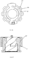
- the present invention is provided that the blade is composed oft two arc shaped single bodies, two single bodies 40 and the convex body 24 of the sleeve surround to a circle so as to couple to the internal wall surface of the housing in a ring shape, at least one end of at least one single body of the blade 4 is once formed with a through groove 43, the through groove 43 is coupled to the coupling surface 241 of the convex body 24 of the sleeve to form an oil passage, the coupling surface is inclined, so that when the blade 4 closes the first passage, the section area of the oil passage 61 is small, as figured in FIG.12 , when the blade 4 opens the first passage, the section area of the oil passage 62 is larger, as figured in FIG.12 , it thus efficiently ensures that the seat cover lifts up quickly and drops down slowly.
- the damping spindle mechanism with self compensation of the present invention is provided that the second passage disposed between the first chamber body 31 and the second chamber body 32 is used to connect the two chamber bodies, the section of the second passage has changing diameter, so that the flow rate of the damping oil is changed in the second passage.
- the spindle 1 of the present invention is disposed with a central spindle 12 with reducing internal diameter, the internal diameter reducing central spindle 12 and the sleeve 2 surround to form the second passage, the internal diameter of the central spindle 12with reducing internal diameter is gradually increased from the end near the first chamber body to the other end near the second chamber body.
- the section area of the second passage is gradually narrowed from the end near to the first chamber body to the end near to the second chamber body, when the seat cover drops down at the beginning, it has the largest section area of the second passage, the damping oil in the second chamber body 32 flows quickly to the first chamber body 31, the resistance to the seat cover is weak, with the seat cover drops down, the section area of the second passage gradually decreases, the resistance to the seat cover gradually increases, at the end of the dropping of the seat cover, the resistance to the seat cover is the largest, it slows down the dropping of the seat cover with well effect.
- the damping spindle mechanism with self compensation of this embodiment differs from the first embodiment in that: the spindle 1 is not applied with the central spindle with internal diameter gradually changed, but a central spindle 13 with saltation internal diameter, the central spindle 13 with saltation internal diameter and the sleeve 2 surround to from the second passage, the internal diameter of the central spindle 13 with saltation internal diameter is suddenly increased from the end near the first chamber body to the other end near the second chamber body.
- the damping spindle mechanism with self compensation of this embodiment differs from the first embodiment in that: the spindle 1 is not applied with the central spindle with internal diameter gradually changed, but a gradually changing first slot 14 in the axial direction, the gradually changing first slot 14 and the sleeve 2 surround to form the second passage, the gradually changing first slot 14 is gradually narrowed from the end near the first chamber body to the other end near the second chamber body
- the damping spindle mechanism with self compensation of this embodiment differs from the first embodiment in that: the spindle 1 is not applied with the central spindle with internal diameter gradually changed, but a gradient second slot 15 in the axial direction, the gradient second slot 15 and the sleeve surround to form the second passage, the gradient second slot 15 is gradiently narrowed from the end near the first chamber body to the other end near the second chamber body
- the damping spindle mechanism with self compensation of this embodiment differs from the first embodiment in that: the spindle 1 is not applied with the central spindle with internal diameter gradually changed, but not a spindle with internal diameter gradually changed, the external thread 11 of the spindle is disposed with gradually changing third slot 16 in the thread direction, the gradually changing third slot 16 and the sleeve 2 surround to form the second passage, the gradually changing third slot 16 is gradually narrowed in screw way from the end near the first chamber body to the other end near the second chamber body.
- the damping spindle mechanism with self compensation of this embodiment differs from the first embodiment in that: another second passage is disposed between the sleeve and the housing, so that the structure of the housing is different from that of the first embodiment, the housing 3 is disposed with a chamber body 34 with internal diameter gradually changing, the chamber wall of the chamber body 34 with internal diameter gradually changing and the sleeve 2 surround to form the second passage, the internal diameter of the chamber body 34 with internal diameter gradually changing is gradually narrowed from the end near the first chamber body to the other end near the second chamber body.
- the spindle has the internal diameter with same size.
- the damping spindle mechanism with self compensation of this embodiment differs from the sixth embodiment in that: the housing is not disposed with a chamber body with gradually changing internal diameter, but the housing 3 is disposed with a chamber body 35 with saltation internal diameter, the chamber wall of the chamber body 35 with saltation internal diameter and the sleeve 2 surround to form the second passage, the internal diameter of the chamber body 35 with saltation internal diameter is suddenly decreased from the end near the first chamber body to the other end near the second chamber body.
- the damping spindle mechanism with self compensation of this embodiment differs from the sixth embodiment in that: the housing is not disposed with a chamber body with gradually changing internal diameter, but the chamber wall of the chamber body of the housing 3 is disposed with a gradually changing fourth slot 36 in the axial direction, the gradually changing fourth slot 36 and the sleeve 2 surround to form the second passage, the gradually changing fourth slot 36 is gradually narrowed from the end near the first chamber body to the other end near the second chamber body
- the damping spindle mechanism with self compensation of this embodiment differs from the sixth embodiment in that: the housing is not disposed with a chamber body with gradually changing internal diameter, but the chamber wall of the chamber body of the housing 3 is disposed with a gradient fifth slot 37 in the axial direction, the gradient fifth slot 37 and the sleeve 2 surround to form the second passage, the gradient fifth slot 37 is gradiently narrowed from the end near the first chamber to the other end near the second chamber body.
- the damping spindle mechanism with self compensation of this embodiment differs from the first embodiment in that: the first passage is a second through hole 27 disposed at the sleeve 2 in the axial direction of the spindle.
- the damping spindle mechanism with self compensation of this embodiment differs from the first embodiment in that: the oil passage is a first through hole 44 disposed in the blade along the axial direction.
- the damping spindle mechanism with self compensation of this embodiment differs from the first embodiment in that: the oil passage is disposed between the blade and the sleeve, the oil passage comprises a gap 45 disposed at one single body of the blade 4 and a first groove 28 disposed at the sleeve corresponding to the gap.
- the second passage can be independently disposed between the sleeve and the spindle, or between the sleeve and the housing; at the same way, the second passage can be disposed both between the sleeve and the spindle and between he sleeve and the housing, for example, the spindle has a central spindle with saltation internal diameter, the housing is applied with a chamber body with a gradually changing internal diameter; in another example, the central spindle of the spindle is disposed with an axial first a gradually changing first slot in the axial direction, the chamber wall of the chamber body of the housing is disposed with a gradient fifth slot in the axial direction; other combinations are available.
- the present invention can be applied widely, such as in the toilet seat cover, the fridge door, telephone flip cover, cabinet door and varies door/cover products, it can be also applied in a drawer, as the present invention is provided that the damping oil moves axially along the spindle, it has longer route than the case that the damping oil moves circumferentially along the spindle, therefore the rectilinear motion of the drawer is transformed to rotation of the spindle.
- the invention may be summarized as follows:
- the present invention is provided with a self compensation mechanism that the first thin wall of the blade deforms towards the internal wall surface of the housing and the second thin wall deforms towards the external wall surface of the spindle when damping is needed, so that it can self compensate the gap due to mechanical wear to make the damping spindle mechanism keep in a stable state in long period, thus lengthening the service life of the damping spindle mechanism.
Landscapes
- Engineering & Computer Science (AREA)
- General Engineering & Computer Science (AREA)
- Mechanical Engineering (AREA)
- Fluid-Damping Devices (AREA)
- Pivots And Pivotal Connections (AREA)
- Toilet Supplies (AREA)
Claims (19)
- Ein Dämpfdrehschaftmechanismus mit Selbst-Kompensation, der einen Drehschaft (1), eine Hülse (2), ein Gehäuse (3) und eine Klinge (4) aufweist; die Hülse (2) ist mit dem Drehschaft (1) auf eine Gewindeart gekuppelt; eine Anti-Dreh-Struktur ist zwischen der Hülse (2) und dem Gehäuse (3) angeordnet, wenn sich der Drehschaft (1) dreht, bewegt sich die Hülse (2) nach vorne und nach hinten entlang der Achse des Drehschafts (1) in dem Gehäuse (3); das Gehäuse (3) ist mit einer Kammer angeordnet, ein Abschnitt des Drehschafts (1), gewindemäßig mit der Hülse (2) verbunden, ist in der Kammer des Gehäuses (3) zusammengebaut, um eine geschlossene Kammer zu bilden; die geschlossene Kammer ist mit Dämpföl gefüllt und durch die Hülse (2) in einen ersten Kammerkörper (31) und einen zweiten Kammerkörper (32) getrennt; die Hülse (2) ist mit einem ersten Durchlass angeordnet, welcher die zwei Kammerkörper in der axialen Richtung verbindet; wobei die Klinge (4) von einer Ringform oder einer Bogenform ist, und zwar gekuppelt an die Innenwandoberfläche des Gehäuses (3), dadurch gekennzeichnet, dass die Klinge (4) mit einer deformierbaren ersten dünnen Wand (41) angeordnet ist, wenn die Klinge (4) sich zu dem zweiten Kammerkörper (32) bewegt, deformiert sich die erste dünne Wand (41) zu der Innenwandoberfläche des Gehäuses (3) hin.
- Der Dämpfdrehschaftmechanismus mit Selbst-Kompensation gemäß Anspruch 1, wobei die Innenwand der Hülse (2) mit der Außenwand des Drehschafts (1) gekuppelt ist, die Innenwand von einem Ende der Hülse (2) in der Nähe des zweiten Kammerkörpers (32) ist mit einer zweiten dünnen Wand (22) von einer Deformation angeordnet, wenn sich die Hülse (2) zu dem zweiten Kammerkörper (32) hin bewegt, deformiert sich die dünne Wand zu der Außenwandoberfläche des Drehschafts (1) hin.
- Der Dämpfdrehschaftmechanismus mit Selbst-Kompensation gemäß Anspruch 1 oder Anspruch 2, wobei die Klinge (4) mit einem ersten Hohlraum (42) angeordnet, welcher zu der ersten dünnen Wand (41) anliegend ist, die Ausnehmung des ersten Hohlraums (42) der Klinge (4) weist zu dem zweiten Kammerkörper (32) hin, so dass, wenn sich die Klinge (4) zu dem zweiten Kammerkörper (32) hin bewegt, die Ausnehmung des ersten Hohlraums (42) die erste dünne Wand (42) nach außen unter der Wirkung des Dämpföls öffnet.
- Der Dämpfdrehschaftmechanismus mit Selbst-Kompensation gemäß Anspruch 2, wobei die Hülse (2) mit einem zweiten Hohlraum (23) angeordnet ist, der zu der zweiten dünnen Wand (22) anliegend ist, die Ausnehmung des zweiten Hohlraums (23) der Hülse (2) weist zu dem zweiten Kammerkörper (32) hin, so dass, wenn sich die Hülse (2) zu dem zweiten Kammerkörper (32) hinbewegt, die Ausnehmung des zweiten Hohlraums (23) die zweite dünne Wand (22) nach außen unter der Wirkung des Dämpföls öffnet.
- Der Dämpfdrehschaftmechanismus mit Selbst-Kompensation gemäß Anspruch 1, wobei ein Öldurchlass in der Klinge (4) oder zwischen der Klinge (4) und der Hülse (2) angeordnet ist.
- Der Dämpfdrehschaftmechanismus mit Selbst-Kompensation gemäß Anspruch 5, wobei die Klinge (4) wenigstens zwei Bogen-Einzel-Körper (40) aufweist, die Einzel-Körper (40) umgeben zu einem Kreis oder die Einzel-Körper (40) und der konvexe Körper der Hülse (2) umgeben zu einem Kreis, um mit der Innenwandoberfläche des Gehäuses (3) in einer Ringform zu kuppeln.
- Der Dämpfdrehschaftmechanismus mit Selbst-Kompensation gemäß Anspruch 6, wobei der Abschnitt des Einzel-Körpers (40) V-förmig, U-förmig, E-förmig, T-förmig, W-förmig oder C-förmig ist.
- Der Dämpfdrehschaftmechanismus mit Selbst-Kompensation gemäß Anspruch 5, Anspruch 6 oder Anspruch 7, wobei der Öldurchlass ein erstes Durchgangsloch ist, das in der Klinge (4) entlang der axialen Richtung angeordnet ist.
- Der Dämpfdrehschaftmechanismus mit Selbst-Kompensation gemäß Anspruch 6 oder Anspruch 7, wobei der Öldurchlass zwischen der Klinge (4) und der Hülse (2) angeordnet ist, der Öldurchlass einen Spalt, welcher an einem Einzel-Körper (40) der Klinge (4) angeordnet ist, und eine erste Nut, die an der Hülse (2), und zwar entsprechend dem Spalt, angeordnet ist, aufweist; der Öldurchlass ist zwischen der Klinge (4) und der Hülse (2) angeordnet, der Öldurchlass weist eine Durchgangsnut (43), und zwar einmal gebildet an dem wenigstens einem Ende des Einzel-Körpers (40) der Klinge (4), und eine Passoberfläche (241) des konvexen Körpers der Hülse (2) auf, die Passoberfläche ist eine geneigte Oberfläche.
- Der Dämpfdrehschaftmechanismus mit Selbst-Kompensation gemäß Anspruch 1, wobei der erste Durchlass eine zweite Nut (25) ist, die einmal an der Außenwand der Hülse (2) in der axialen Richtung des Drehschafts (1) gebildet ist; der erste Durchlass ist ein zweites Durchgangsloch, das an der Hülse (2) in der axialen Richtung des Drehschafts (1) angeordnet ist.
- Der Dämpfdrehschaftmechanismus mit Selbst-Kompensation gemäß Anspruch 1, wobei die Anti-Dreh-Struktur eine erste Rippe (26), die an der Außenwand der Hülse (2) in der axialen Richtung angeordnet ist, und eine zweite Rippe (33), die an der Innenwand des Gehäuses (3) in der axialen Richtung angeordnet ist, aufweist, die erste Rippe (26) und die zweite Rippe (33) sind fehlangepasst.
- Der Dämpfdrehschaftmechanismus mit Selbst-Kompensation gemäß Anspruch 1, wobei ein zweiter Durchlass zwischen dem ersten Kammerkörper (31) und dem zweiten Kammerkörper (32) angeordnet ist, um die zwei Kammerkörper (40) zu verbinden, wobei der Abschnitt des zweiten Durchlasses sich verkleinert, so dass sich die Strömungskonstante des Dämpföls in dem zweiten Durchlass verändert.
- Der Dämpfdrehschaftmechanismus mit Selbst-Kompensation gemäß Anspruch 12, wobei der zweite Durchlass zwischen der Hülse (2) und dem Drehschaft (1) angeordnet ist.
- Der Dämpfdrehschaftmechanismus mit Selbst-Kompensation gemäß Anspruch 13, wobei der Drehschaft (1) mit einem zentralen Drehschaft mit sich verkleinernden Innendurchmesser angeordnet ist, der zentrale Drehschaft mit sich verkleinernden Innendurchmesser und die Hülse (2) umgeben, um den zweiten Durchlass zu bilden, der Innendurchmesser des zentralen Drehschafts mit sich verkleinerndem Innendurchmesser wird allmählich von dem Ende in der Nähe des ersten Kammerkörpers (31) zu dem anderen Ende in der Nähe des zweiten Kammerkörpers (32) erhöht; oder im anderen Fall, der Drehschaft (2) ist mit einem zentralen Drehschaft mit Sprung-Innendurchmesser angeordnet, der zentrale Drehschaft mit Sprung-Innendurchmesser und die Hülse (2) umgeben, um den zweiten Durchlass zu bilden, der Innendurchmesser des zentralen Drehschafts mit Sprung-Innendurchmesser wird plötzlich von dem Ende in der Nähe des ersten Kammerkörpers (31) zu dem anderen Ende in der Nähe des zweiten Kammerkörpers (32) erhöht.
- Der Dämpfdrehschaftmechanismus mit Selbst-Kompensation gemäß Anspruch 13, wobei der zentrale Drehschaft des Drehschafts (1) mit einem sich allmählich ändernden ersten Schlitz (14) in der axialen Richtung angeordnet ist, der sich allmählich ändernde erste Schlitz (14) und die Hülse (2) umgeben, um den zweiten Durchlass zu bilden, der sich allmählich ändernde erste Schlitz (14) wird allmählich von dem Ende in der Nähe des ersten Kammerkörpers (31) zu dem anderen Ende in der Nähe des zweiten Kammerkörpers (32) verengt; oder im anderen Fall, der zentrale Drehschaft des Drehschafts (1) ist ein gradientartiger zweiter Schlitz (15) in der axialen Richtung, der gradientartige zweite Schlitz (15) und die Hülse (2) umgeben, um den zweiten Durchlass zu bilden, der gradientartige zweite Schlitz (15) wird grandientartig von dem Ende in der Nähe des ersten Kammerkörpers (31) zu dem anderen Ende in der Nähe des zweiten Kammerkörpers (32) verengt.
- Der Dämpfdrehschaftmechanismus mit Selbst-Kompensation gemäß Anspruch 13, wobei das Außengewinde des Drehschafts (1) mit einem sich allmählich ändernden dritten Schlitz (16) in der Gewinderichtung angeordnet ist, der sich allmählich ändernde dritte Schlitz (16) und die Hülse (2) umgeben, um den zweiten Durchlass zu bilden, der sich allmählich ändernde dritte Schlitz (16) wird allmählich in einer Schraubenart von dem Ende in der Nähe des ersten Kammerkörpers (31) zu dem anderen Ende in der Nähe des zweiten Kammerkörpers (32) verengt.
- Der Dämpfdrehschaftmechanismus mit Selbst-Kompensation gemäß Anspruch 12 oder Anspruch 13, wobei der zweite Durchlass zwischen der Hülse (2) und dem Gehäuse (3) angeordnet ist.
- Der Dämpfdrehschaftmechanismus mit Selbst-Kompensation gemäß Anspruch 17, wobei das Gehäuse (3) mit einem Kammerkörper mit einem sich allmählich ändernden Innendurchmesser angeordnet ist, die Kammerwand des Kammerkörpers mit sich allmählich ändernden Innendurchmesser und die Hülse (2) umgeben, um den zweiten Durchlass zu bilden, der Innendurchmesser des Kammerkörpers mit sich allmählich ändernden Innendurchmesser wird allmählich von dem Ende in der Nähe des ersten Kammerkörpers (31) zu dem anderen Ende in der Nähe des zweiten Kammerkörpers (32) verengt; oder im anderen Fall, das Gehäuse (3) ist mit einem Kammerkörper mit Sprung-Innendurchmesser angeordnet, die Kammerwand des Kammerkörpers mit Sprung-Innendurchmesser und die Hülse (2) umgeben, um den zweiten Durchlass zu bilden, der Innendurchmesser des Kammerkörpers mit Sprung-Innendurchmesser wird plötzlich von dem Ende in der Nähe des ersten Kammerkörpers (31) zu dem anderen Ende in der Nähe des zweiten Kammerkörpers (32) verringert.
- Der Dämpfdrehschaftmechanismus mit Selbst-Kompensation gemäß Anspruch 17, wobei die Kammerwand des Kammerkörpers des Gehäuses (3) mit einem sich allmählich ändernden vierten Schlitz (36) in der axialen Richtung angeordnet ist, der sich allmählich ändernde vierte Schlitz (36) und die Hülse umgeben, um den zweiten Durchlass zu bilden, der sich allmählich ändernde vierte Schlitz (36) wird allmählich von dem Ende in der Nähe des ersten Kammerkörpers (31) zu dem anderen Ende in der Nähe des zweiten Kammerkörpers (32) verengt; oder im anderen Fall, die Kammerwand des Kammerkörpers des Gehäuses (3) ist mit einem grandientartigen fünften Schlitz (37) in der axialen Richtung angeordnet, der gradientartige fünfte Schlitz (37) und die Hülse (2) umgeben, um den zweiten Durchlass zu bilden, der gradientartige fünfte Schlitz ist gradientartig von dem Ende in der Nähe der ersten Kammer zu dem anderen Ende in der Nähe des zweiten Kammerkörpers (32) verengt.
Applications Claiming Priority (3)
| Application Number | Priority Date | Filing Date | Title |
|---|---|---|---|
| CN201420137851.6U CN203784082U (zh) | 2014-03-25 | 2014-03-25 | 带自补偿的阻尼转轴机构 |
| CN201410114089.4A CN103967925B (zh) | 2014-03-25 | 2014-03-25 | 一种带自补偿的阻尼转轴机构 |
| PCT/CN2015/074930 WO2015144034A1 (zh) | 2014-03-25 | 2015-03-24 | 一种带自补偿的阻尼转轴机构 |
Publications (3)
| Publication Number | Publication Date |
|---|---|
| EP3124809A1 EP3124809A1 (de) | 2017-02-01 |
| EP3124809A4 EP3124809A4 (de) | 2017-12-20 |
| EP3124809B1 true EP3124809B1 (de) | 2020-01-29 |
Family
ID=54193984
Family Applications (1)
| Application Number | Title | Priority Date | Filing Date |
|---|---|---|---|
| EP15767895.4A Active EP3124809B1 (de) | 2014-03-25 | 2015-03-24 | Dämpfender drehschaftmechanismus mit automatischer kompensation |
Country Status (4)
| Country | Link |
|---|---|
| US (1) | US20170138433A1 (de) |
| EP (1) | EP3124809B1 (de) |
| JP (1) | JP6722373B2 (de) |
| WO (1) | WO2015144034A1 (de) |
Families Citing this family (12)
| Publication number | Priority date | Publication date | Assignee | Title |
|---|---|---|---|---|
| CN105781303B (zh) * | 2016-01-29 | 2017-07-11 | 王湘冀 | 一种阻尼器 |
| CN105650185B (zh) * | 2016-02-02 | 2017-10-13 | 王湘冀 | 一种衰减自修复的旋转阻尼器 |
| DK179102B1 (en) * | 2016-05-04 | 2017-10-30 | Pressalit As | Hinge arrangement for toilet seat and/or cover |
| US10612722B2 (en) * | 2017-11-22 | 2020-04-07 | Hamilton Sundstrand Corporation | Threaded lube restrictor for low flow applications |
| WO2020010220A1 (en) | 2018-07-06 | 2020-01-09 | Boundy Tim J | Systems and devices for adjustable door closure control |
| AU2022205967A1 (en) | 2021-01-08 | 2023-07-13 | Moshun, Llc. | Systems and devices for motion control |
| CN113048144B (zh) * | 2021-01-28 | 2023-01-31 | 陆安民 | 一种缓冲器 |
| PL4083467T3 (pl) * | 2021-04-30 | 2025-11-12 | Geberit International Ag | Amortyzator do obrotowego ruchu, zwłaszcza desek lub siedzisk toalety |
| US12473768B2 (en) | 2022-03-23 | 2025-11-18 | Moshun, LLC | Systems and devices for motion control |
| CN114992229B (zh) * | 2022-08-05 | 2022-12-16 | 荣耀终端有限公司 | 一种转动机构和折叠终端 |
| CN116658512B (zh) * | 2022-10-27 | 2024-03-29 | 荣耀终端有限公司 | 转动机构和可折叠电子设备 |
| CN116250754B (zh) * | 2023-02-27 | 2025-06-17 | 厦门豪帝卫浴工业有限公司 | 一种旋转式阻尼机构 |
Family Cites Families (16)
| Publication number | Priority date | Publication date | Assignee | Title |
|---|---|---|---|---|
| US1759266A (en) * | 1925-01-17 | 1930-05-20 | Louis L Lomar | Snubber |
| US1651895A (en) * | 1926-07-14 | 1927-12-06 | Edward J Kolodziej | Shock absorber |
| US1747306A (en) * | 1926-08-13 | 1930-02-18 | Edward J Kolodziej | Shock absorber |
| JPS57179651U (de) * | 1981-05-11 | 1982-11-13 | ||
| JPS5946772U (ja) * | 1982-09-20 | 1984-03-28 | トヨタ自動車株式会社 | 自動車用ステアリング装置におけるエネルギ吸収装置 |
| JP3525307B2 (ja) * | 1994-11-29 | 2004-05-10 | 日本発条株式会社 | 緩衝装置におけるオリフィス構造 |
| US6464052B1 (en) * | 2002-02-13 | 2002-10-15 | Chun-Sung Hsiao | Rotatable hydraulic damper |
| CN2688964Y (zh) * | 2004-04-26 | 2005-03-30 | 兆利资讯工业股份有限公司 | 阻尼式转轴 |
| JP2007255446A (ja) * | 2006-03-20 | 2007-10-04 | Fuji Latex Kk | ショック・アブソーバ |
| CN201033049Y (zh) * | 2007-05-17 | 2008-03-12 | 王湘冀 | 翻板的慢落机构 |
| JP5097075B2 (ja) * | 2008-09-30 | 2012-12-12 | 日本電産サンキョー株式会社 | ダンパー装置 |
| EP2295693A1 (de) * | 2009-08-27 | 2011-03-16 | Joseph Talpe | Türschließmechanismus |
| US9115519B2 (en) * | 2011-01-14 | 2015-08-25 | Feiyong Li | Damping structure |
| JP5702208B2 (ja) * | 2011-03-31 | 2015-04-15 | オイレス工業株式会社 | ロータリダンパ |
| CN102578952B (zh) * | 2012-03-21 | 2014-04-23 | 厦门豪帝卫浴工业有限公司 | 一种阻尼可调的旋转缓冲器 |
| JP2014009774A (ja) * | 2012-06-29 | 2014-01-20 | Nidec Sankyo Corp | ダンパー装置 |
-
2015
- 2015-03-24 EP EP15767895.4A patent/EP3124809B1/de active Active
- 2015-03-24 US US15/127,688 patent/US20170138433A1/en not_active Abandoned
- 2015-03-24 JP JP2017501451A patent/JP6722373B2/ja not_active Expired - Fee Related
- 2015-03-24 WO PCT/CN2015/074930 patent/WO2015144034A1/zh not_active Ceased
Non-Patent Citations (1)
| Title |
|---|
| None * |
Also Published As
| Publication number | Publication date |
|---|---|
| JP6722373B2 (ja) | 2020-07-15 |
| WO2015144034A1 (zh) | 2015-10-01 |
| EP3124809A4 (de) | 2017-12-20 |
| JP2017512961A (ja) | 2017-05-25 |
| US20170138433A1 (en) | 2017-05-18 |
| EP3124809A1 (de) | 2017-02-01 |
Similar Documents
| Publication | Publication Date | Title |
|---|---|---|
| US20170138433A1 (en) | Damping spindle mechanism with self compensation | |
| US11555637B2 (en) | Electronic expansion valve | |
| EP2350413B1 (de) | Dämpfer | |
| US7837070B2 (en) | Simplified pump for dispensing fluid substances withdrawn from a container | |
| CN102913503B (zh) | 流体压力缸 | |
| CN110296246B (zh) | 电子膨胀阀 | |
| JP2003210267A (ja) | 家具の可動部分用エアダンパー | |
| EP3336396A1 (de) | Elektronisches expansionsventil | |
| US12467555B2 (en) | Check valve damping | |
| JPH07293622A (ja) | ガス封入緩衝部材 | |
| CN108716334A (zh) | 一种自动回位阻尼门铰 | |
| EP2966250A1 (de) | Türverschluss | |
| US20120175830A1 (en) | Buffer | |
| JP2011163525A (ja) | エアダンパ | |
| EP2366916A1 (de) | Dämpfer | |
| US20120091641A1 (en) | Air pressure buffer | |
| WO2009081894A1 (ja) | ダンパ装置 | |
| CN100406769C (zh) | 流体阻尼器 | |
| CN102734313B (zh) | 倾斜铰链及具有倾斜铰链的电子装置 | |
| CN107165967A (zh) | 缓冲装置 | |
| JP2016508552A (ja) | 緩衝機構付きドア用蝶番 | |
| JP2015074980A (ja) | オイルジェット | |
| CN103967925B (zh) | 一种带自补偿的阻尼转轴机构 | |
| CN103512287B (zh) | 一种电子膨胀阀 | |
| CN105020257A (zh) | 一种具有密封自补偿的阻尼转轴机构 |
Legal Events
| Date | Code | Title | Description |
|---|---|---|---|
| STAA | Information on the status of an ep patent application or granted ep patent |
Free format text: STATUS: THE INTERNATIONAL PUBLICATION HAS BEEN MADE |
|
| PUAI | Public reference made under article 153(3) epc to a published international application that has entered the european phase |
Free format text: ORIGINAL CODE: 0009012 |
|
| STAA | Information on the status of an ep patent application or granted ep patent |
Free format text: STATUS: REQUEST FOR EXAMINATION WAS MADE |
|
| 17P | Request for examination filed |
Effective date: 20161025 |
|
| AK | Designated contracting states |
Kind code of ref document: A1 Designated state(s): AL AT BE BG CH CY CZ DE DK EE ES FI FR GB GR HR HU IE IS IT LI LT LU LV MC MK MT NL NO PL PT RO RS SE SI SK SM TR |
|
| AX | Request for extension of the european patent |
Extension state: BA ME |
|
| DAV | Request for validation of the european patent (deleted) | ||
| DAX | Request for extension of the european patent (deleted) | ||
| A4 | Supplementary search report drawn up and despatched |
Effective date: 20171122 |
|
| RIC1 | Information provided on ipc code assigned before grant |
Ipc: F16F 9/16 20060101ALI20171116BHEP Ipc: E05F 3/20 20060101ALI20171116BHEP Ipc: F16F 9/516 20060101ALI20171116BHEP Ipc: F16C 11/04 20060101AFI20171116BHEP Ipc: A47K 13/12 20060101ALI20171116BHEP Ipc: E05F 3/04 20060101ALI20171116BHEP |
|
| STAA | Information on the status of an ep patent application or granted ep patent |
Free format text: STATUS: EXAMINATION IS IN PROGRESS |
|
| 17Q | First examination report despatched |
Effective date: 20180626 |
|
| GRAP | Despatch of communication of intention to grant a patent |
Free format text: ORIGINAL CODE: EPIDOSNIGR1 |
|
| STAA | Information on the status of an ep patent application or granted ep patent |
Free format text: STATUS: GRANT OF PATENT IS INTENDED |
|
| INTG | Intention to grant announced |
Effective date: 20190730 |
|
| GRAS | Grant fee paid |
Free format text: ORIGINAL CODE: EPIDOSNIGR3 |
|
| GRAA | (expected) grant |
Free format text: ORIGINAL CODE: 0009210 |
|
| STAA | Information on the status of an ep patent application or granted ep patent |
Free format text: STATUS: THE PATENT HAS BEEN GRANTED |
|
| AK | Designated contracting states |
Kind code of ref document: B1 Designated state(s): AL AT BE BG CH CY CZ DE DK EE ES FI FR GB GR HR HU IE IS IT LI LT LU LV MC MK MT NL NO PL PT RO RS SE SI SK SM TR |
|
| REG | Reference to a national code |
Ref country code: GB Ref legal event code: FG4D |
|
| REG | Reference to a national code |
Ref country code: CH Ref legal event code: EP |
|
| REG | Reference to a national code |
Ref country code: AT Ref legal event code: REF Ref document number: 1228703 Country of ref document: AT Kind code of ref document: T Effective date: 20200215 |
|
| REG | Reference to a national code |
Ref country code: IE Ref legal event code: FG4D |
|
| REG | Reference to a national code |
Ref country code: DE Ref legal event code: R096 Ref document number: 602015046063 Country of ref document: DE |
|
| REG | Reference to a national code |
Ref country code: CH Ref legal event code: NV Representative=s name: DA VINCI PARTNERS LLC, CH |
|
| REG | Reference to a national code |
Ref country code: NL Ref legal event code: MP Effective date: 20200129 |
|
| PG25 | Lapsed in a contracting state [announced via postgrant information from national office to epo] |
Ref country code: RS Free format text: LAPSE BECAUSE OF FAILURE TO SUBMIT A TRANSLATION OF THE DESCRIPTION OR TO PAY THE FEE WITHIN THE PRESCRIBED TIME-LIMIT Effective date: 20200129 Ref country code: FI Free format text: LAPSE BECAUSE OF FAILURE TO SUBMIT A TRANSLATION OF THE DESCRIPTION OR TO PAY THE FEE WITHIN THE PRESCRIBED TIME-LIMIT Effective date: 20200129 Ref country code: NO Free format text: LAPSE BECAUSE OF FAILURE TO SUBMIT A TRANSLATION OF THE DESCRIPTION OR TO PAY THE FEE WITHIN THE PRESCRIBED TIME-LIMIT Effective date: 20200429 Ref country code: PT Free format text: LAPSE BECAUSE OF FAILURE TO SUBMIT A TRANSLATION OF THE DESCRIPTION OR TO PAY THE FEE WITHIN THE PRESCRIBED TIME-LIMIT Effective date: 20200621 |
|
| REG | Reference to a national code |
Ref country code: LT Ref legal event code: MG4D |
|
| PG25 | Lapsed in a contracting state [announced via postgrant information from national office to epo] |
Ref country code: HR Free format text: LAPSE BECAUSE OF FAILURE TO SUBMIT A TRANSLATION OF THE DESCRIPTION OR TO PAY THE FEE WITHIN THE PRESCRIBED TIME-LIMIT Effective date: 20200129 Ref country code: SE Free format text: LAPSE BECAUSE OF FAILURE TO SUBMIT A TRANSLATION OF THE DESCRIPTION OR TO PAY THE FEE WITHIN THE PRESCRIBED TIME-LIMIT Effective date: 20200129 Ref country code: LV Free format text: LAPSE BECAUSE OF FAILURE TO SUBMIT A TRANSLATION OF THE DESCRIPTION OR TO PAY THE FEE WITHIN THE PRESCRIBED TIME-LIMIT Effective date: 20200129 Ref country code: IS Free format text: LAPSE BECAUSE OF FAILURE TO SUBMIT A TRANSLATION OF THE DESCRIPTION OR TO PAY THE FEE WITHIN THE PRESCRIBED TIME-LIMIT Effective date: 20200529 Ref country code: BG Free format text: LAPSE BECAUSE OF FAILURE TO SUBMIT A TRANSLATION OF THE DESCRIPTION OR TO PAY THE FEE WITHIN THE PRESCRIBED TIME-LIMIT Effective date: 20200429 Ref country code: GR Free format text: LAPSE BECAUSE OF FAILURE TO SUBMIT A TRANSLATION OF THE DESCRIPTION OR TO PAY THE FEE WITHIN THE PRESCRIBED TIME-LIMIT Effective date: 20200430 |
|
| PG25 | Lapsed in a contracting state [announced via postgrant information from national office to epo] |
Ref country code: NL Free format text: LAPSE BECAUSE OF FAILURE TO SUBMIT A TRANSLATION OF THE DESCRIPTION OR TO PAY THE FEE WITHIN THE PRESCRIBED TIME-LIMIT Effective date: 20200129 |
|
| PG25 | Lapsed in a contracting state [announced via postgrant information from national office to epo] |
Ref country code: RO Free format text: LAPSE BECAUSE OF FAILURE TO SUBMIT A TRANSLATION OF THE DESCRIPTION OR TO PAY THE FEE WITHIN THE PRESCRIBED TIME-LIMIT Effective date: 20200129 Ref country code: CZ Free format text: LAPSE BECAUSE OF FAILURE TO SUBMIT A TRANSLATION OF THE DESCRIPTION OR TO PAY THE FEE WITHIN THE PRESCRIBED TIME-LIMIT Effective date: 20200129 Ref country code: SK Free format text: LAPSE BECAUSE OF FAILURE TO SUBMIT A TRANSLATION OF THE DESCRIPTION OR TO PAY THE FEE WITHIN THE PRESCRIBED TIME-LIMIT Effective date: 20200129 Ref country code: LT Free format text: LAPSE BECAUSE OF FAILURE TO SUBMIT A TRANSLATION OF THE DESCRIPTION OR TO PAY THE FEE WITHIN THE PRESCRIBED TIME-LIMIT Effective date: 20200129 Ref country code: ES Free format text: LAPSE BECAUSE OF FAILURE TO SUBMIT A TRANSLATION OF THE DESCRIPTION OR TO PAY THE FEE WITHIN THE PRESCRIBED TIME-LIMIT Effective date: 20200129 Ref country code: DK Free format text: LAPSE BECAUSE OF FAILURE TO SUBMIT A TRANSLATION OF THE DESCRIPTION OR TO PAY THE FEE WITHIN THE PRESCRIBED TIME-LIMIT Effective date: 20200129 Ref country code: EE Free format text: LAPSE BECAUSE OF FAILURE TO SUBMIT A TRANSLATION OF THE DESCRIPTION OR TO PAY THE FEE WITHIN THE PRESCRIBED TIME-LIMIT Effective date: 20200129 Ref country code: MC Free format text: LAPSE BECAUSE OF FAILURE TO SUBMIT A TRANSLATION OF THE DESCRIPTION OR TO PAY THE FEE WITHIN THE PRESCRIBED TIME-LIMIT Effective date: 20200129 Ref country code: SM Free format text: LAPSE BECAUSE OF FAILURE TO SUBMIT A TRANSLATION OF THE DESCRIPTION OR TO PAY THE FEE WITHIN THE PRESCRIBED TIME-LIMIT Effective date: 20200129 |
|
| REG | Reference to a national code |
Ref country code: DE Ref legal event code: R097 Ref document number: 602015046063 Country of ref document: DE |
|
| REG | Reference to a national code |
Ref country code: AT Ref legal event code: MK05 Ref document number: 1228703 Country of ref document: AT Kind code of ref document: T Effective date: 20200129 |
|
| PLBE | No opposition filed within time limit |
Free format text: ORIGINAL CODE: 0009261 |
|
| STAA | Information on the status of an ep patent application or granted ep patent |
Free format text: STATUS: NO OPPOSITION FILED WITHIN TIME LIMIT |
|
| REG | Reference to a national code |
Ref country code: BE Ref legal event code: MM Effective date: 20200331 |
|
| PG25 | Lapsed in a contracting state [announced via postgrant information from national office to epo] |
Ref country code: LU Free format text: LAPSE BECAUSE OF NON-PAYMENT OF DUE FEES Effective date: 20200324 |
|
| 26N | No opposition filed |
Effective date: 20201030 |
|
| PG25 | Lapsed in a contracting state [announced via postgrant information from national office to epo] |
Ref country code: AT Free format text: LAPSE BECAUSE OF FAILURE TO SUBMIT A TRANSLATION OF THE DESCRIPTION OR TO PAY THE FEE WITHIN THE PRESCRIBED TIME-LIMIT Effective date: 20200129 Ref country code: IE Free format text: LAPSE BECAUSE OF NON-PAYMENT OF DUE FEES Effective date: 20200324 Ref country code: IT Free format text: LAPSE BECAUSE OF FAILURE TO SUBMIT A TRANSLATION OF THE DESCRIPTION OR TO PAY THE FEE WITHIN THE PRESCRIBED TIME-LIMIT Effective date: 20200129 |
|
| PG25 | Lapsed in a contracting state [announced via postgrant information from national office to epo] |
Ref country code: SI Free format text: LAPSE BECAUSE OF FAILURE TO SUBMIT A TRANSLATION OF THE DESCRIPTION OR TO PAY THE FEE WITHIN THE PRESCRIBED TIME-LIMIT Effective date: 20200129 Ref country code: BE Free format text: LAPSE BECAUSE OF NON-PAYMENT OF DUE FEES Effective date: 20200331 Ref country code: PL Free format text: LAPSE BECAUSE OF FAILURE TO SUBMIT A TRANSLATION OF THE DESCRIPTION OR TO PAY THE FEE WITHIN THE PRESCRIBED TIME-LIMIT Effective date: 20200129 |
|
| PG25 | Lapsed in a contracting state [announced via postgrant information from national office to epo] |
Ref country code: TR Free format text: LAPSE BECAUSE OF FAILURE TO SUBMIT A TRANSLATION OF THE DESCRIPTION OR TO PAY THE FEE WITHIN THE PRESCRIBED TIME-LIMIT Effective date: 20200129 Ref country code: MT Free format text: LAPSE BECAUSE OF FAILURE TO SUBMIT A TRANSLATION OF THE DESCRIPTION OR TO PAY THE FEE WITHIN THE PRESCRIBED TIME-LIMIT Effective date: 20200129 Ref country code: CY Free format text: LAPSE BECAUSE OF FAILURE TO SUBMIT A TRANSLATION OF THE DESCRIPTION OR TO PAY THE FEE WITHIN THE PRESCRIBED TIME-LIMIT Effective date: 20200129 |
|
| PG25 | Lapsed in a contracting state [announced via postgrant information from national office to epo] |
Ref country code: MK Free format text: LAPSE BECAUSE OF FAILURE TO SUBMIT A TRANSLATION OF THE DESCRIPTION OR TO PAY THE FEE WITHIN THE PRESCRIBED TIME-LIMIT Effective date: 20200129 Ref country code: AL Free format text: LAPSE BECAUSE OF FAILURE TO SUBMIT A TRANSLATION OF THE DESCRIPTION OR TO PAY THE FEE WITHIN THE PRESCRIBED TIME-LIMIT Effective date: 20200129 |
|
| PGFP | Annual fee paid to national office [announced via postgrant information from national office to epo] |
Ref country code: FR Payment date: 20230320 Year of fee payment: 9 |
|
| PGFP | Annual fee paid to national office [announced via postgrant information from national office to epo] |
Ref country code: GB Payment date: 20230323 Year of fee payment: 9 Ref country code: DE Payment date: 20221222 Year of fee payment: 9 |
|
| PGFP | Annual fee paid to national office [announced via postgrant information from national office to epo] |
Ref country code: CH Payment date: 20230402 Year of fee payment: 9 |
|
| REG | Reference to a national code |
Ref country code: DE Ref legal event code: R119 Ref document number: 602015046063 Country of ref document: DE |
|
| REG | Reference to a national code |
Ref country code: CH Ref legal event code: PL |
|
| GBPC | Gb: european patent ceased through non-payment of renewal fee |
Effective date: 20240324 |
|
| PG25 | Lapsed in a contracting state [announced via postgrant information from national office to epo] |
Ref country code: DE Free format text: LAPSE BECAUSE OF NON-PAYMENT OF DUE FEES Effective date: 20241001 |
|
| PG25 | Lapsed in a contracting state [announced via postgrant information from national office to epo] |
Ref country code: GB Free format text: LAPSE BECAUSE OF NON-PAYMENT OF DUE FEES Effective date: 20240324 |
|
| PG25 | Lapsed in a contracting state [announced via postgrant information from national office to epo] |
Ref country code: FR Free format text: LAPSE BECAUSE OF NON-PAYMENT OF DUE FEES Effective date: 20240331 |
|
| PG25 | Lapsed in a contracting state [announced via postgrant information from national office to epo] |
Ref country code: GB Free format text: LAPSE BECAUSE OF NON-PAYMENT OF DUE FEES Effective date: 20240324 Ref country code: FR Free format text: LAPSE BECAUSE OF NON-PAYMENT OF DUE FEES Effective date: 20240331 Ref country code: DE Free format text: LAPSE BECAUSE OF NON-PAYMENT OF DUE FEES Effective date: 20241001 Ref country code: CH Free format text: LAPSE BECAUSE OF NON-PAYMENT OF DUE FEES Effective date: 20240331 |