EP3124858A1 - Appareil d'affichage - Google Patents
Appareil d'affichage Download PDFInfo
- Publication number
- EP3124858A1 EP3124858A1 EP16180456.2A EP16180456A EP3124858A1 EP 3124858 A1 EP3124858 A1 EP 3124858A1 EP 16180456 A EP16180456 A EP 16180456A EP 3124858 A1 EP3124858 A1 EP 3124858A1
- Authority
- EP
- European Patent Office
- Prior art keywords
- guide plate
- light guide
- light
- guide member
- display apparatus
- Prior art date
- Legal status (The legal status is an assumption and is not a legal conclusion. Google has not performed a legal analysis and makes no representation as to the accuracy of the status listed.)
- Withdrawn
Links
Images


Classifications
-
- G—PHYSICS
- G02—OPTICS
- G02F—OPTICAL DEVICES OR ARRANGEMENTS FOR THE CONTROL OF LIGHT BY MODIFICATION OF THE OPTICAL PROPERTIES OF THE MEDIA OF THE ELEMENTS INVOLVED THEREIN; NON-LINEAR OPTICS; FREQUENCY-CHANGING OF LIGHT; OPTICAL LOGIC ELEMENTS; OPTICAL ANALOGUE/DIGITAL CONVERTERS
- G02F1/00—Devices or arrangements for the control of the intensity, colour, phase, polarisation or direction of light arriving from an independent light source, e.g. switching, gating or modulating; Non-linear optics
- G02F1/01—Devices or arrangements for the control of the intensity, colour, phase, polarisation or direction of light arriving from an independent light source, e.g. switching, gating or modulating; Non-linear optics for the control of the intensity, phase, polarisation or colour
- G02F1/13—Devices or arrangements for the control of the intensity, colour, phase, polarisation or direction of light arriving from an independent light source, e.g. switching, gating or modulating; Non-linear optics for the control of the intensity, phase, polarisation or colour based on liquid crystals, e.g. single liquid crystal display cells
- G02F1/133—Constructional arrangements; Operation of liquid crystal cells; Circuit arrangements
- G02F1/1333—Constructional arrangements; Manufacturing methods
- G02F1/133308—Support structures for LCD panels, e.g. frames or bezels
-
- G—PHYSICS
- G02—OPTICS
- G02B—OPTICAL ELEMENTS, SYSTEMS OR APPARATUS
- G02B6/00—Light guides; Structural details of arrangements comprising light guides and other optical elements, e.g. couplings
- G02B6/0001—Light guides; Structural details of arrangements comprising light guides and other optical elements, e.g. couplings specially adapted for lighting devices or systems
- G02B6/0011—Light guides; Structural details of arrangements comprising light guides and other optical elements, e.g. couplings specially adapted for lighting devices or systems the light guides being planar or of plate-like form
- G02B6/0013—Means for improving the coupling-in of light from the light source into the light guide
- G02B6/0023—Means for improving the coupling-in of light from the light source into the light guide provided by one optical element, or plurality thereof, placed between the light guide and the light source, or around the light source
- G02B6/0025—Diffusing sheet or layer; Prismatic sheet or layer
-
- G—PHYSICS
- G02—OPTICS
- G02B—OPTICAL ELEMENTS, SYSTEMS OR APPARATUS
- G02B6/00—Light guides; Structural details of arrangements comprising light guides and other optical elements, e.g. couplings
- G02B6/0001—Light guides; Structural details of arrangements comprising light guides and other optical elements, e.g. couplings specially adapted for lighting devices or systems
- G02B6/0011—Light guides; Structural details of arrangements comprising light guides and other optical elements, e.g. couplings specially adapted for lighting devices or systems the light guides being planar or of plate-like form
- G02B6/0081—Mechanical or electrical aspects of the light guide and light source in the lighting device peculiar to the adaptation to planar light guides, e.g. concerning packaging
- G02B6/0086—Positioning aspects
- G02B6/0088—Positioning aspects of the light guide or other optical sheets in the package
-
- G—PHYSICS
- G02—OPTICS
- G02F—OPTICAL DEVICES OR ARRANGEMENTS FOR THE CONTROL OF LIGHT BY MODIFICATION OF THE OPTICAL PROPERTIES OF THE MEDIA OF THE ELEMENTS INVOLVED THEREIN; NON-LINEAR OPTICS; FREQUENCY-CHANGING OF LIGHT; OPTICAL LOGIC ELEMENTS; OPTICAL ANALOGUE/DIGITAL CONVERTERS
- G02F1/00—Devices or arrangements for the control of the intensity, colour, phase, polarisation or direction of light arriving from an independent light source, e.g. switching, gating or modulating; Non-linear optics
- G02F1/01—Devices or arrangements for the control of the intensity, colour, phase, polarisation or direction of light arriving from an independent light source, e.g. switching, gating or modulating; Non-linear optics for the control of the intensity, phase, polarisation or colour
- G02F1/13—Devices or arrangements for the control of the intensity, colour, phase, polarisation or direction of light arriving from an independent light source, e.g. switching, gating or modulating; Non-linear optics for the control of the intensity, phase, polarisation or colour based on liquid crystals, e.g. single liquid crystal display cells
- G02F1/133—Constructional arrangements; Operation of liquid crystal cells; Circuit arrangements
- G02F1/1333—Constructional arrangements; Manufacturing methods
- G02F1/1335—Structural association of cells with optical devices, e.g. polarisers or reflectors
- G02F1/1336—Illuminating devices
-
- G—PHYSICS
- G02—OPTICS
- G02F—OPTICAL DEVICES OR ARRANGEMENTS FOR THE CONTROL OF LIGHT BY MODIFICATION OF THE OPTICAL PROPERTIES OF THE MEDIA OF THE ELEMENTS INVOLVED THEREIN; NON-LINEAR OPTICS; FREQUENCY-CHANGING OF LIGHT; OPTICAL LOGIC ELEMENTS; OPTICAL ANALOGUE/DIGITAL CONVERTERS
- G02F1/00—Devices or arrangements for the control of the intensity, colour, phase, polarisation or direction of light arriving from an independent light source, e.g. switching, gating or modulating; Non-linear optics
- G02F1/01—Devices or arrangements for the control of the intensity, colour, phase, polarisation or direction of light arriving from an independent light source, e.g. switching, gating or modulating; Non-linear optics for the control of the intensity, phase, polarisation or colour
- G02F1/13—Devices or arrangements for the control of the intensity, colour, phase, polarisation or direction of light arriving from an independent light source, e.g. switching, gating or modulating; Non-linear optics for the control of the intensity, phase, polarisation or colour based on liquid crystals, e.g. single liquid crystal display cells
- G02F1/133—Constructional arrangements; Operation of liquid crystal cells; Circuit arrangements
- G02F1/1333—Constructional arrangements; Manufacturing methods
- G02F1/133308—Support structures for LCD panels, e.g. frames or bezels
- G02F1/133317—Intermediate frames, e.g. between backlight housing and front frame
Definitions
- Apparatuses consistent with exemplary embodiments of the present disclosure relate to a backlight apparatus having a backlight unit for supplying light to a display panel.
- a display apparatus is equipment for displaying an image on a screen.
- Examples of the display apparatus include a monitor, a television, etc.
- the display apparatus includes a display panel implemented as a liquid crystal panel to display an image on a screen, and a backlight which supplies light to the display panel.
- the backlight includes an edge type backlight having a light guide plate disposed behind the display panel, and a plurality of light sources arranged along both sides of the light guide plate to emit light.
- a backlight including, as a light source unit, a substrate and Light Emitting Diodes (LEDs) arranged on the substrate has been developed.
- LEDs Light Emitting Diodes
- One or more exemplary embodiments provide a display apparatus capable of reducing the generation of a bright area and a dark area.
- a display apparatus including: a display panel, a light guide plate disposed behind the display panel, at least one light source disposed to face at least one side surface of the light guide plate, and at least one guide member disposed between the at least on side surface of the light guide plate and the at least one light source, and configured to support at least one of a front part of the at least one side surface of the light guide plate and a back part of the at least one side surface of the light guide plate.
- the at least one light source may include a substrate, and a plurality of light emitting diodes (LEDs) arranged on the substrate to face the at least one side surface of the light guide plate, and the guide member restrictively supports the LEDs and the at least one of the front part of the at least one side surface of the light guide plate and the back part of the at least one side surface of the light guide plate.
- LEDs light emitting diodes
- the display apparatus may further include a middle mold configured to support the display panel, and a bottom chassis configured to accommodate the light guide plate therein, wherein the guide member is disposed in one of the middle mold and the bottom chassis.
- the at least one guide member may be integrated into the middle mold and protrude from the middle mold.
- the at least one guide member may be formed by modifying a part of the bottom chassis.
- the at least one guide member may be formed as a separate component relative to the bottom chassis, and matingly engaged in the bottom chassis.
- the at least one guide member may include an installation part extending parallel to the bottom chassis, and a guide part protruding from the installation part and supporting the at least one side surface of the light guide plate.
- the display apparatus may further include a diffusion member disposed between the at least one guide member and the at least one side surface of the light guide plate, and configured to diffuse light.
- the display apparatus may further include a transparent member disposed between the at least one guide member and the diffusion member.
- a display apparatus including a display panel, a light guide plate disposed behind the display panel, a middle mold configured to support edges of the display panel, a bottom chassis configured to accommodate the light guide plate, a plurality of LEDs disposed to face at least one side surface of the light guide plate, a first guide member disposed in the middle mold between the at least one side surface of the light guide plate and the plurality of LEDs, the first guide member may be configured to support a front part of the at least one side surface of the light guide plate, and a second guide member disposed in the bottom chassis between the at least one side surface of the light guide plate and the plurality of LEDs, the second guide member may be configured to support a back part of the at least one side surface of the light guide plate, wherein the first guide member is spaced from the second guide member, and faces the second guide member.
- the display apparatus may further include a diffusion member disposed between the first guide member and the second guide member and the at least one side surface of the light guide plate.
- the display apparatus may further include a transparent member disposed between the first guide member and the second guide member and the diffusion member.
- the second guide member may be formed as a separate component relative to the bottom chassis, and may be matingly engaged in the bottom chassis.
- the plurality of LEDs may be aligned to face an upper side surface and a lower side surface of the light guide plate, and a pair of first guide members and a pair of second guide members may be provided to support the upper side surface and the lower side surface of the light guide plate.
- a display apparatus 1 may include a display module 10 to display images, and a case 20 to accommodate the display module 10, the case 20 forming an outer appearance of the display apparatus 1.
- the rear part of the case 20 may be connected to a stand 30 that enables the display apparatus 1 to stand on a horizontal plane.
- the display module 10 may include, as shown in FIGS. 2 and 3 , a display panel 11 configured to display images, a backlight 12 configured to generate light and to supply the light to the display panel 11, a middle mold 13 in which the display panel 11 is rested and which is configured to support the edges of the display panel 11, a top chassis 14 coupled with the front part of the middle mold 13 and configured to maintain the display panel 11 at its state installed in the middle mold 13, and a bottom chassis 15 configured to accommodate the backlight 12 and coupled with the rear part of the middle mold 13.
- the display panel 11 may be a liquid crystal panel in the shape of a quadrangular flat plate but is not limited thereto.
- the backlight 12 may include a light source 121 to generate light, and a light guide plate 122 to guide light generated by the light source 121 to the display panel 11.
- the light source 121 may include a substrate 121a, and a plurality of light emitting diodes (LEDs) 121b arranged on the substrate 121a.
- LEDs light emitting diodes
- the light guide plate 122 may be made of a transparent material in order to transmit and guide light, formed in the shape of a quadrangular flat plate to correspond to the display panel 11, and disposed behind the display panel 11. On the rear surface of the light guide plate 122, a reflective sheet 122a may be disposed to reflect light in a front direction.
- two light sources 121 may be provided. Accordingly, two substrates 121a may be respectively provided in the light sources 121.
- the substrates 121a may extend in a horizontal direction to correspond to the upper and lower side surfaces of the light guide plate 122, and the LEDs 121b of the two light sources 121 may be arranged in a line on the substrates 121a to face the upper and lower side surfaces of the light guide plate 122. Accordingly, light generated by the LEDs 121a may be incident to the inside of the light guide plate 122 through the upper and lower side surfaces of the light guide plate 122.
- the middle mold 13 may include a panel resting part 13a on which the display panel 11 is rested in the front direction, and a bottom coupling part 13b extending from the panel resting part 13a in a back direction and coupled with the bottom chassis 15.
- the top chassis 14 may include a bezel part 14a to support the front edge parts of the display panel 11, and a top side part 14b extending from the bezel part 14a in the back direction and coupled with the middle mold 13.
- the bottom chassis 15 may include a bottom rear part 15a which is formed in the shape of a quadrangular flat plate and on which the light guide plate 122 is rested, and a bottom side part 15b extending from the borders of the bottom rear part 15a in the front direction and coupled with the middle mold 13. On the rear surface of the bottom rear part 15a, various kinds of substrates for controlling operations of the display apparatus 1 may be mounted.
- the display apparatus 1 may include a plurality of optical sheets 16A, 16B, and 16C disposed between the display panel 11 and the light guide plate 122, and configured to improve the properties of light.
- the plurality of optical sheets 16A, 16B, and 16C may include an optical sheet 16A configured to diffuse light exiting the front surface of the light guide plate 122, a prism sheet 16B disposed in front of the diffusion sheet 16A and configured to focus light diffused by the diffusion sheet 16A and transfer the focused light in a direction that is vertical to the front surface, and a protective sheet 16C disposed in front of the prism sheet 16B and configured to protect the prism sheet 16B.
- the optical sheets 16A, 16B, and 16C may be supported by the middle mold 13.
- the display apparatus 1 may include a plurality of guide members 13c and 15c configured to support the upper, lower, left, and right side surfaces of the light guide plate 122.
- the guide members 13c and 15c may be disposed between the light source 121 and at least one side surface of the light guide plate 122, and support the side surface of the light guide plate 122.
- the guide members 13c and 15c may include a first guide member 13c provided in the middle mold 13, and a second guide member 15c provided in the bottom chassis 15.
- the first guide member 13c and the second guide member 15c may extend in the width direction of the light guide plate 122, and may be formed in the shape of a quadrangular bar.
- the first guide member 13c may be integrated into the middle mold 13 when the middle mold 13 is injection molded with resin
- the second guide member 15c may be integrated into the bottom rear part 15a by bending a part of the bottom rear part 15a when a metal plate is manufactured by press-forming or the like, but embodiments are not limited thereto.
- the first guide member 13c may restrictively support a front part of the side surface of the light guide plate 122, and the second guide member 15c may restrictively support a back part of the side surface of the light guide plate 122. Also, the first guide member 13c and the second guide member 15c may be spaced a predetermined distance from each other. Accordingly, light generated by the LEDs 121b may be transferred to the side surface of the light guide plate 122 via a space between the first guide member 13c and the second guide member 15c, and then incident to the inside of the light guide plate 122.
- FIG. 3 a state in which the light source 121 is disposed to face the lower side surface of the light guide plate 122, and the guide members 13c and 15c support the lower side surface of the light guide plate 122 is shown.
- the upper side surface of the light guide plate 122 may also be supported by the guide members 13c and 15c. That is, two first guide members 13c may be respectively formed in the upper and lower parts of the middle mold 13, and two second guide members 15c may be respectively formed in the upper and lower parts of the bottom chassis 15 in correspondence to the first guide members 13c.
- the upper and lower side parts of the light guide plate 122 are supported by the guide members 13c and 15c, gaps between the light sources 121 and the light guide plate 122 can be maintained constant by the guide members 13c and 15c, and deformation of the light guide plate 122 due to thermal expansion can be suppressed to some degree.
- the first and second guide members 13c and 15c may function to prevent a bright area (that is, a relatively brighter area than its peripheral area) or a dark area (that is, a relatively darker area than its peripheral area) from being generated in the light guide plate 122.
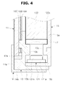
- FIG. 4 shows a sectional view of a display module according to a second exemplary embodiment.
- a display module 10 may include a display panel 11, a light guide plate 122, a middle mold 13, a bottom chassis 15, and a top chassis 14, which have the same shapes as the corresponding components described above. Also, a first guide member 13c may be provided in the middle mold 13, and a second guide member 15c may be provided in the bottom chassis 15, wherein the heights in up-down direction of the first and second guide members 13c and 15c may be lower than those of the first and second guide members 13c and 15c of the first exemplary embodiment described above. Also, between the first and second guide members 13c and 15c and a side surface (that is, the lower side surface of the light guide plate 122 in FIG. 4 ) of the light guide plate 122, a diffusion member 17 for diffusing light may be disposed between the first and second guide members 13c and 15c and a side surface (that is, the lower side surface of the light guide plate 122 in FIG. 4 ) of the light guide plate 122.
- a diffusion member 17 for diffusing light may be disposed between the
- the side surface of the light guide plate 122 may be supported indirectly by the diffusion member 17.
- the diffusion member 17 may be made of a white translucent material to diffuse light. Accordingly, light generated by the LEDs 121b may be transferred to the diffusion member 17 through the space between the first guide member 13c and the second guide member 15c, and the light transferred to the diffusion member 17 may be diffused by the diffusion member 17 and then transmitted to the side surface of the light guide plate 122. Accordingly, light having an entirely uniform distribution may be incident to the side surface of the light guide plate 122, so that the generation of a bright area and a dark area in the light guide plate 122 can be further suppressed compared to the first exemplary embodiment described above.
- FIG. 5 is a cross-sectional view of a display module according to a third exemplary embodiment.
- a display module 10 may include a display panel 11, a light guide plate 122, a middle mold 13, a bottom chassis 15, and a top chassis 14, which have the same shapes as the corresponding components descried above
- a first guide member 13c may be provided in the middle mold 13
- a second guide member 15c may be provided in the bottom chassis 15, wherein the heights in up-down direction of the first and second guide members 13c and 15c may be relatively lower than those of the first and second guide members 13c and 15c of the second exemplary embodiment described above.
- a side surface that is, the lower side surface of the light guide plate 122 in FIG.
- a diffusion member 17 for diffusing light, and a transparent member 18 made of a transparent material to transmit light may be disposed in order. Accordingly, the side surface of the light guide plate 122 may be supported indirectly by the diffusion member 17 and the transparent member 18.
- the transparent member 18 and the diffusion member 17 are disposed between the first and second guide members 13c and 15c and the side surface of the light guide plate 122, a space through which the light generated by the LEDs 121b can be diffused in a fan shape can be ensured by the transparent member 18. Accordingly, light generated by the LEDs 121b may pass through the transparent member 18 to be diffused in a fan shape, and then be incident to the diffusion member 17. The light transferred to the diffusion member 17 may be again diffused by the diffusion member 17, and then transferred to the side surface of the light guide plate 122. Accordingly, light having an entirely uniform distribution may be incident to the side surface of the light guide plate 122, so that the generation of a bright area and a dark area in the light guide plate 122 can be further suppressed compared to the second exemplary embodiment described above.
- the light sources 121 may be respectively disposed below and above the light guide plate 122 to irradiate light toward the lower and upper side surfaces of the light guide plate 122.
- the light sources 121 may additionally or alternatively be respectively disposed to the left and right of the light guide plate 122 so as to supply light toward the left and right side surfaces of the light guide plate 122.
- the guide members 13c and 15c may include the first guide member 13c provided in the middle mold 13 and the second guide member 15c provided in the bottom chassis 15.
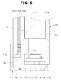
- the guide member 13c may be provided in the middle mold 13, as shown as a fourth exemplary embodiment in FIG. 6
- only the guide member 15c may be provided in the bottom chassis 15, as shown as a fifth exemplary embodiment in FIG. 7 .
- the method in which the guide member 13c or 15c is provided only in any one of the middle mold 13 and the bottom chassis 15, as described above, may be effective when the guide member 13c or 15c does not need to support the load of the light guide plate 122 since other guide members are disposed to support the left and right side surfaces of the light guide plate 122.
- the second guide member 15c provided in the bottom chassis 15 may be formed by modifying a part of the bottom chassis 15.
- a guide member 19 may be fabricated separately from the bottom chassis 15, and then installed in the bottom chassis 15.
- the guide member 19 may include an installation part 19a disposed in parallel to the bottom rear part 15a forming the rear surface of the bottom chassis 15 and installed in the bottom rear part 15a, and a guide part 19b protruding from the installation part 19a in the front direction and supporting a side surface of the light guide plate 122.
Landscapes
- Physics & Mathematics (AREA)
- Nonlinear Science (AREA)
- General Physics & Mathematics (AREA)
- Optics & Photonics (AREA)
- Mathematical Physics (AREA)
- Chemical & Material Sciences (AREA)
- Crystallography & Structural Chemistry (AREA)
- Planar Illumination Modules (AREA)
- Liquid Crystal (AREA)
- Illuminated Signs And Luminous Advertising (AREA)
Applications Claiming Priority (1)
| Application Number | Priority Date | Filing Date | Title |
|---|---|---|---|
| KR1020150106250A KR20170013516A (ko) | 2015-07-28 | 2015-07-28 | 디스플레이 장치 |
Publications (1)
| Publication Number | Publication Date |
|---|---|
| EP3124858A1 true EP3124858A1 (fr) | 2017-02-01 |
Family
ID=56876891
Family Applications (1)
| Application Number | Title | Priority Date | Filing Date |
|---|---|---|---|
| EP16180456.2A Withdrawn EP3124858A1 (fr) | 2015-07-28 | 2016-07-20 | Appareil d'affichage |
Country Status (4)
| Country | Link |
|---|---|
| US (1) | US20170031087A1 (fr) |
| EP (1) | EP3124858A1 (fr) |
| KR (1) | KR20170013516A (fr) |
| CN (1) | CN106405906A (fr) |
Families Citing this family (4)
| Publication number | Priority date | Publication date | Assignee | Title |
|---|---|---|---|---|
| JP6701023B2 (ja) * | 2016-07-29 | 2020-05-27 | キヤノン株式会社 | 撮像装置、画像処理方法、画像処理システム、及び画像処理プログラム |
| KR102382506B1 (ko) * | 2017-10-24 | 2022-04-05 | 삼성전자주식회사 | 디스플레이 장치 |
| JP7028712B2 (ja) * | 2018-05-18 | 2022-03-02 | 株式会社デンソーテン | 照明装置および操作装置 |
| US10928575B2 (en) * | 2019-07-02 | 2021-02-23 | Dell Products L.P. | Beveled light guide plate |
Citations (11)
| Publication number | Priority date | Publication date | Assignee | Title |
|---|---|---|---|---|
| US5280372A (en) * | 1992-08-03 | 1994-01-18 | Sharp Kabushiki Kaisha | Liquid crystal display device |
| US5453855A (en) * | 1992-12-15 | 1995-09-26 | Koito Manufacturing Co., Ltd. | Liquid crystal display device backlit by LED's coupled to printed circuit board |
| US20050018415A1 (en) * | 2001-10-05 | 2005-01-27 | Makoto Shimizu | Lighting unit and liquid crystal display device using the unit |
| US20090273947A1 (en) * | 2006-11-16 | 2009-11-05 | Enplas Corporation | Surface light source device and display |
| US20120120678A1 (en) * | 2010-11-15 | 2012-05-17 | Young Lighting Technology Corporation | Backlight module |
| US20120281151A1 (en) * | 2010-01-29 | 2012-11-08 | Sharp Kabushiki Kaisha | Lighting device, display device and television receiver |
| WO2013106553A1 (fr) * | 2012-01-13 | 2013-07-18 | Qd Vision, Inc. | Chambre de mélange de lumière destinée à être utilisée avec une plaque de guidage de lumière |
| US20140003090A1 (en) * | 2011-05-16 | 2014-01-02 | Shenzhen China Star Optoelectronics Technology Co., Ltd. | Liquid crystal display and backlight module thereof |
| CN103775925A (zh) * | 2014-02-25 | 2014-05-07 | 深圳市华星光电技术有限公司 | 背光模组 |
| CN103823320A (zh) * | 2014-03-14 | 2014-05-28 | 深圳市华星光电技术有限公司 | 背光模组 |
| WO2015012135A1 (fr) * | 2013-07-26 | 2015-01-29 | 堺ディスプレイプロダクト株式会社 | Unité d'éclairage et dispositif d'affichage à cristaux liquides |
Family Cites Families (10)
| Publication number | Priority date | Publication date | Assignee | Title |
|---|---|---|---|---|
| KR100652058B1 (ko) * | 2004-06-30 | 2006-12-01 | 엘지.필립스 엘시디 주식회사 | 백라이트 유닛 |
| JP4640188B2 (ja) * | 2006-01-18 | 2011-03-02 | 三菱電機株式会社 | 面状光源装置 |
| JP2008117730A (ja) * | 2006-11-08 | 2008-05-22 | Enplas Corp | 面光源装置及びこれを備えた表示装置 |
| US8368843B2 (en) * | 2008-03-28 | 2013-02-05 | Sharp Kabushiki Kaisha | Backlight unit and liquid crystal display device |
| WO2010004794A1 (fr) * | 2008-07-10 | 2010-01-14 | シャープ株式会社 | Dispositif de rétroéclairage et dispositif d'affichage plat l'utilisant |
| JP5939004B2 (ja) * | 2012-04-11 | 2016-06-22 | ソニー株式会社 | 発光装置、表示装置および照明装置 |
| WO2014034546A1 (fr) * | 2012-08-31 | 2014-03-06 | シャープ株式会社 | Appareil d'affichage et récepteur de télévision |
| KR20150117751A (ko) * | 2014-04-10 | 2015-10-21 | 삼성디스플레이 주식회사 | 표시 장치 |
| KR20160009720A (ko) * | 2014-07-16 | 2016-01-27 | 삼성디스플레이 주식회사 | 백라이트 유닛 |
| CN104635380B (zh) * | 2015-03-02 | 2017-10-24 | 深圳市华星光电技术有限公司 | 具有量子条的背光模组以及液晶显示装置 |
-
2015
- 2015-07-28 KR KR1020150106250A patent/KR20170013516A/ko not_active Withdrawn
-
2016
- 2016-07-20 EP EP16180456.2A patent/EP3124858A1/fr not_active Withdrawn
- 2016-07-28 CN CN201610607695.9A patent/CN106405906A/zh not_active Withdrawn
- 2016-07-28 US US15/221,687 patent/US20170031087A1/en not_active Abandoned
Patent Citations (11)
| Publication number | Priority date | Publication date | Assignee | Title |
|---|---|---|---|---|
| US5280372A (en) * | 1992-08-03 | 1994-01-18 | Sharp Kabushiki Kaisha | Liquid crystal display device |
| US5453855A (en) * | 1992-12-15 | 1995-09-26 | Koito Manufacturing Co., Ltd. | Liquid crystal display device backlit by LED's coupled to printed circuit board |
| US20050018415A1 (en) * | 2001-10-05 | 2005-01-27 | Makoto Shimizu | Lighting unit and liquid crystal display device using the unit |
| US20090273947A1 (en) * | 2006-11-16 | 2009-11-05 | Enplas Corporation | Surface light source device and display |
| US20120281151A1 (en) * | 2010-01-29 | 2012-11-08 | Sharp Kabushiki Kaisha | Lighting device, display device and television receiver |
| US20120120678A1 (en) * | 2010-11-15 | 2012-05-17 | Young Lighting Technology Corporation | Backlight module |
| US20140003090A1 (en) * | 2011-05-16 | 2014-01-02 | Shenzhen China Star Optoelectronics Technology Co., Ltd. | Liquid crystal display and backlight module thereof |
| WO2013106553A1 (fr) * | 2012-01-13 | 2013-07-18 | Qd Vision, Inc. | Chambre de mélange de lumière destinée à être utilisée avec une plaque de guidage de lumière |
| WO2015012135A1 (fr) * | 2013-07-26 | 2015-01-29 | 堺ディスプレイプロダクト株式会社 | Unité d'éclairage et dispositif d'affichage à cristaux liquides |
| CN103775925A (zh) * | 2014-02-25 | 2014-05-07 | 深圳市华星光电技术有限公司 | 背光模组 |
| CN103823320A (zh) * | 2014-03-14 | 2014-05-28 | 深圳市华星光电技术有限公司 | 背光模组 |
Also Published As
| Publication number | Publication date |
|---|---|
| CN106405906A (zh) | 2017-02-15 |
| KR20170013516A (ko) | 2017-02-07 |
| US20170031087A1 (en) | 2017-02-02 |
Similar Documents
| Publication | Publication Date | Title |
|---|---|---|
| KR102034890B1 (ko) | 곡면 디스플레이 장치 | |
| US9535208B2 (en) | Bendable display apparatus having a guide unit which guides a light guide plate | |
| KR102243856B1 (ko) | 표시 장치 | |
| EP3029517A1 (fr) | Appareil d'affichage avec rétroéclairage | |
| US10261231B2 (en) | Display apparatus | |
| US20140211123A1 (en) | Display module and display apparatus having the same | |
| CN104882070B (zh) | 显示装置 | |
| KR102171307B1 (ko) | 입체 영상 디스플레이 장치 및 그 제조 방법 | |
| EP2887661A1 (fr) | Appareil pour afficher une image tridimensionnelle | |
| US10649256B2 (en) | Panel module and display apparatus having the same | |
| EP3124858A1 (fr) | Appareil d'affichage | |
| US20140300844A1 (en) | Display device | |
| CN103529595A (zh) | 显示装置 | |
| EP3457201A1 (fr) | Afficheur | |
| US20210003873A1 (en) | Image display apparatus | |
| US11327220B2 (en) | Display apparatus including a support slot and a support protrusion | |
| CN106803400A (zh) | 无边框显示装置 | |
| KR20130051133A (ko) | 액정패널조립체 및 그를 구비한 액정 디스플레이 장치 | |
| KR102190035B1 (ko) | 디스플레이 장치 | |
| US9905169B2 (en) | Display device | |
| KR102493918B1 (ko) | 디스플레이 장치 | |
| KR101633583B1 (ko) | 디스플레이 장치 및 이의 백라이트 어셈블리 | |
| EP3185070B1 (fr) | Dispositif d'affichage | |
| KR20150105870A (ko) | 디스플레이 장치 | |
| US20190187512A1 (en) | Display unit and display apparatus having the same |
Legal Events
| Date | Code | Title | Description |
|---|---|---|---|
| PUAI | Public reference made under article 153(3) epc to a published international application that has entered the european phase |
Free format text: ORIGINAL CODE: 0009012 |
|
| STAA | Information on the status of an ep patent application or granted ep patent |
Free format text: STATUS: THE APPLICATION HAS BEEN PUBLISHED |
|
| AK | Designated contracting states |
Kind code of ref document: A1 Designated state(s): AL AT BE BG CH CY CZ DE DK EE ES FI FR GB GR HR HU IE IS IT LI LT LU LV MC MK MT NL NO PL PT RO RS SE SI SK SM TR |
|
| AX | Request for extension of the european patent |
Extension state: BA ME |
|
| STAA | Information on the status of an ep patent application or granted ep patent |
Free format text: STATUS: REQUEST FOR EXAMINATION WAS MADE |
|
| 17P | Request for examination filed |
Effective date: 20170406 |
|
| RBV | Designated contracting states (corrected) |
Designated state(s): AL AT BE BG CH CY CZ DE DK EE ES FI FR GB GR HR HU IE IS IT LI LT LU LV MC MK MT NL NO PL PT RO RS SE SI SK SM TR |
|
| STAA | Information on the status of an ep patent application or granted ep patent |
Free format text: STATUS: EXAMINATION IS IN PROGRESS |
|
| 17Q | First examination report despatched |
Effective date: 20180219 |
|
| STAA | Information on the status of an ep patent application or granted ep patent |
Free format text: STATUS: THE APPLICATION IS DEEMED TO BE WITHDRAWN |
|
| 18D | Application deemed to be withdrawn |
Effective date: 20201008 |