EP3124873A1 - Four de cuisson domestique - Google Patents
Four de cuisson domestique Download PDFInfo
- Publication number
- EP3124873A1 EP3124873A1 EP15178519.3A EP15178519A EP3124873A1 EP 3124873 A1 EP3124873 A1 EP 3124873A1 EP 15178519 A EP15178519 A EP 15178519A EP 3124873 A1 EP3124873 A1 EP 3124873A1
- Authority
- EP
- European Patent Office
- Prior art keywords
- cooking
- temperature
- program
- selection
- control system
- Prior art date
- Legal status (The legal status is an assumption and is not a legal conclusion. Google has not performed a legal analysis and makes no representation as to the accuracy of the status listed.)
- Withdrawn
Links
- 238000010411 cooking Methods 0.000 title claims abstract description 191
- 238000010438 heat treatment Methods 0.000 claims abstract description 75
- 238000000605 extraction Methods 0.000 claims abstract description 26
- 239000003517 fume Substances 0.000 claims abstract description 11
- 238000009877 rendering Methods 0.000 claims abstract description 3
- 230000001276 controlling effect Effects 0.000 abstract 3
- 230000001105 regulatory effect Effects 0.000 abstract 1
- 235000013305 food Nutrition 0.000 description 18
- 238000011084 recovery Methods 0.000 description 12
- 238000000034 method Methods 0.000 description 9
- 230000004913 activation Effects 0.000 description 6
- 238000005192 partition Methods 0.000 description 6
- 230000009471 action Effects 0.000 description 5
- 235000008429 bread Nutrition 0.000 description 4
- 238000011161 development Methods 0.000 description 4
- 230000008569 process Effects 0.000 description 4
- 238000004891 communication Methods 0.000 description 3
- 238000012790 confirmation Methods 0.000 description 3
- 238000007726 management method Methods 0.000 description 3
- 238000012986 modification Methods 0.000 description 3
- 230000004048 modification Effects 0.000 description 3
- 230000015572 biosynthetic process Effects 0.000 description 2
- 238000010586 diagram Methods 0.000 description 2
- 238000001035 drying Methods 0.000 description 2
- 230000000694 effects Effects 0.000 description 2
- 230000002093 peripheral effect Effects 0.000 description 2
- 238000012360 testing method Methods 0.000 description 2
- 230000002411 adverse Effects 0.000 description 1
- 238000004458 analytical method Methods 0.000 description 1
- 235000015278 beef Nutrition 0.000 description 1
- 239000000919 ceramic Substances 0.000 description 1
- 238000001311 chemical methods and process Methods 0.000 description 1
- 238000004040 coloring Methods 0.000 description 1
- 230000003111 delayed effect Effects 0.000 description 1
- 239000012530 fluid Substances 0.000 description 1
- 239000011521 glass Substances 0.000 description 1
- 238000009413 insulation Methods 0.000 description 1
- 235000013372 meat Nutrition 0.000 description 1
- 239000002184 metal Substances 0.000 description 1
- 239000000203 mixture Substances 0.000 description 1
- 238000003825 pressing Methods 0.000 description 1
- 230000003068 static effect Effects 0.000 description 1
- 230000000007 visual effect Effects 0.000 description 1
- XLYOFNOQVPJJNP-UHFFFAOYSA-N water Substances O XLYOFNOQVPJJNP-UHFFFAOYSA-N 0.000 description 1
Images


Classifications
-
- F—MECHANICAL ENGINEERING; LIGHTING; HEATING; WEAPONS; BLASTING
- F24—HEATING; RANGES; VENTILATING
- F24C—DOMESTIC STOVES OR RANGES ; DETAILS OF DOMESTIC STOVES OR RANGES, OF GENERAL APPLICATION
- F24C7/00—Stoves or ranges heated by electric energy
- F24C7/08—Arrangement or mounting of control or safety devices
- F24C7/082—Arrangement or mounting of control or safety devices on ranges, e.g. control panels, illumination
- F24C7/085—Arrangement or mounting of control or safety devices on ranges, e.g. control panels, illumination on baking ovens
-
- F—MECHANICAL ENGINEERING; LIGHTING; HEATING; WEAPONS; BLASTING
- F24—HEATING; RANGES; VENTILATING
- F24C—DOMESTIC STOVES OR RANGES ; DETAILS OF DOMESTIC STOVES OR RANGES, OF GENERAL APPLICATION
- F24C15/00—Details
- F24C15/20—Removing cooking fumes
- F24C15/2007—Removing cooking fumes from oven cavities
Definitions
- the present invention relates to household cooking apparatuses in general, and has been developed with particular reference to cooking ovens.
- Ovens of the type referred to typically include a load-bearing structure, associated to which is a muffle defining a cooking cavity. Associated to the muffle is a plurality of heating elements, variously arranged, frequently constituted by electrical resistances.
- the control system of the oven typically includes a control panel with selection means that can be operated by a user for selecting a cooking program from a plurality of possible programs, as well as for manual setting of a desired cooking temperature from a plurality of possible temperatures. Frequently, the control panel of the oven also includes timing means, via which the user can set a desired cooking duration.
- the programs that can be selected by the user are in general programs substantially dedicated to the cooking of classes of foods, where the user can set the desired temperature.
- the user is required to set both the desired program and a corresponding temperature: when the program is being executed, the control system of the oven controls one or more of its heating elements, so as to manage a temperature profile in the cooking cavity that is variable as a function of the temperature selected by the user.
- the aim of the invention is basically to limit the aforesaid drawbacks.
- This aim is achieved, according to the present invention, by a household cooking oven and by a cooking program for a household oven having the characteristics specified in the claims.
- the claims form an integral part of the technical teaching provided herein in relation to the invention.
- references to "an embodiment” or “one embodiment” in the framework of the present description indicates that a particular configuration, structure, or characteristic described in relation to the embodiment is comprised in at least one embodiment.
- phrases such as “in an embodiment” or “in one embodiment” and the like that may be present in various points in the framework of the present description do not necessarily all refer to one and the same embodiment.
- the particular configurations, structures, or characteristics may be combined in any adequate way in one or more embodiments.
- the references used in what follows are provided merely for convenience and do not define the sphere of protection or the scope of the embodiments.
- the oven 1 has a load-bearing structure 2, located within which is a muffle 3, built in a way in itself known, which delimits part of a cooking cavity, designated by CC.
- a front door 4 is hinged to the structure 2, in particular in a lower region thereof, designed to delimit the cooking cavity CC at the front and enable access to the inside thereof.
- a control panel 5 which integrates a user interface described hereinafter, which forms part of a control system of the oven 1.
- the above control system comprises an electronic board, represented only schematically in Figure 1 , where it is designated by CS, preferably comprising a microprocessor control unit.
- the electronic control board CS is connected in signal communication to the aforesaid user interface, as well as to sensor means necessary for controlling operation of the oven, amongst which at least one sensor TS for detecting the temperature within the cooking cavity CC.
- the electronic board CS is configured for driving - preferably using suitable power actuators - various electrical loads of the oven, amongst which at least one fan and a plurality of heating elements.
- the oven according to the invention comprises at least one extraction fan, for expelling cooking fumes/vapours from the muffle 3.
- the oven also comprises a fan for circulation of air within the muffle 3.
- the oven 1 comprises both of the aforesaid fans, the circulation fan being designated by 6 and the extraction fan being designated by 7.
- Each fan 6, 7 has a respective electric motor 6a, 7a, connected to the output shaft of which is a respective impeller 6b, 7b.
- at least the motor 7a of the fan 7 is an adjustable-speed motor, and the control system of the oven is pre-arranged for controlling the speed of the motor.
- the muffle 3 has an intermediate partition wall 3a, which divides the cavity CC of the muffle 3 into a front, cooking, chamber, which extends between the door 4 and the partition wall 3a, and a rear, air-distribution, chamber S, which extends between the partition wall 3a and the rear wall of the muffle 3.
- the cooking chamber there may be preferably positioned one or more shelves at different heights, on which there can be set the containers of the foods to be cooked.
- the impeller 6b of the fan 6 preferably of a centrifugal type with axis of rotation substantially horizontal.
- the impeller 6b is positioned within a region circumscribed by the resistance 8, which preferably has a circular shape.
- the distribution chamber S has an outlet section, for delivery of air to the cooking chamber, as well as an inlet section, for suction of air from the cooking chamber.
- the aforesaid outlet section may comprise a plurality of passages in generally peripheral positions of the distribution chamber S, for example defined between the partition wall 3a and the rear wall or the side walls of the muffle 3, whereas the aforesaid inlet section is defined in a central area of the partition wall 3a, which is configured substantially in the form of a grill and is located in front of the impeller 6b.
- the air is heated by the resistance 8 and pushed towards the peripheral outlet passages of the distribution chamber S, so that it tends to flow along the side walls of the muffle 3, towards the front of the cooking chamber.
- the fan 6 the same air is drawn towards the central grill-shaped area of the partition wall 3a in order to heat by convection the foods that are located on the shelf or shelves arranged within the cooking chamber.
- This "exhausted" air which has yielded heat to the foods, then returns into the distribution chamber S so as to be heated again and re-introduced into the cooking chamber.
- the muffle 3 has a fume/vapour outlet 3b at its upper wall, as well as a channelling 9 that extends above the upper wall of the muffle 3.
- the channelling 9 has an outlet 9a that is located substantially at the front of the oven 1, above an upper portion of the door 4, at least one upper air intake 9b and one lower fume/vapour inlet 9c, in fluid communication with the outlet 3b of the muffle 3.
- the extraction fan 7 is preferably associated to the channelling 9 so as to take in air from the air intake 9b and fumes/vapours from the outlet 3b of the muffle 3 in order to expel a resulting mixture from the outlet 9a.
- the extraction fan 7 is preferably a radial fan, mounted in such a way that its impeller 7b, which is of a centrifugal type, is located within the channelling 9.
- the centrifugal impeller 7b has an upper impeller section and a lower impeller section, which are pre-arranged for taking in air from the inlet 9b and fumes/vapours from the inlet 9c, respectively, with the aforesaid bottom section that is positioned above the inlet 9c, substantially coaxial thereto and to the outlet 3b of the muffle.
- the impeller 7b also enables air intake, in particular from the area that overlies the muffle 3, so as to reduce the temperature in this area, where some functional components of the oven 1 are mounted, amongst which, for example, the electronic control board CS.
- heating elements 10 and 11 are two further heating elements, preferably constituted by electrical resistances, arranged inside and outside the cooking cavity CC, respectively.
- the heating element 10 is positioned in the upper part of the cooking cavity CC to provide a so-called "grill resistance”
- the heating element 11 is positioned underneath the cooking cavity CC, in particular underneath the lower wall of the muffle 3, to provide a so-called "sole resistance”.
- Figure 2 is a schematic illustration of a possible embodiment of the aforesaid user interface, which belongs to the control system of the oven and is connected in signal communication to the electronic control board CS.
- the interface designated as a whole by UI, comprises a first device S1, for manual selection of a cooking program from a plurality of selectable cooking programs, as well as a second device S2, for manual selection of a cooking temperature from a plurality of selectable cooking temperatures.
- the devices S1 and S2 preferably comprise electrical selectors, very preferably with rotatable control knob.
- the selector S1 may be a discrete selector, which identifies a certain number of selection positions, whereas the selector S2 may be a continuous selector, for example of a potentiometric type.
- the selector S1 enables manual selection of eleven programs, identified by the letters A to L.
- the user interface UI may include program-selection means and temperature-selection means different from the selectors S1 and S2, as explained hereinafter.
- the control system and in particular the control unit of the board CS, is able to control execution of programs that can be executed by the oven 1 at least according to a selection made via the selector S1 and a selection made via the selector S2.
- these programs differ from one another as regards the modes and times of activation of the electrical loads that contribute to cooking, and specifically the heating elements 8, 10, 11 and the fans 6, 7.
- the logic that supervises the above modes and times for the various programs is, as has been said, implemented in the control system, in particular in the control unit of the board CS.
- the programs that can be selected via the selector S1 comprise first programs A-H, during which the control system is able to control one or more of the heating elements 8, 10, 11 in order to manage a temperature profile in the cooking cavity CC that is variable as a function of a temperature selected via the selector S2.
- the control system is in any case configured also for enabling, during execution of one of the programs A-H, modification of the selection made via the selector S2, i.e., modification of the desired temperature for the cooking cavity.
- the programs A-H of a generally known conception, may comprise for example a traditional oven program, referred to as "static", a multilevel cooking program, a grill cooking program, a baking program for cakes and the like.
- the duration of the first programs A-H may be varied according to a choice made by the user.
- the user interface UI comprises means for setting a duration of the cooking program and the control system of the oven is configured for controlling execution of the program also as a function of the duration set.
- the user interface UI includes a control means 12, which can be operated for selecting a timing function, a display device 13, and control means 14a, 14b, which can be operated for setting a duration. Via the control means 12, for example a key of a "touch" type, the user can activate programming of the duration, corresponding to which is a graphic representation on the display 13.
- the user can set the desired duration for the cooking program and then confirm his or her choice, for example by pressing again the key 12.
- the means described may be configured also for programming a delayed start of the desired program ("delay timer" function).
- the selector S2 is pre-arranged for enabling a temperature selection of a continuous type.
- temperature levels are in any case shown on the interface UI, here seven temperature levels designated by 60°C, 100°C, 140°C, 160°C, 180°C, 220°C, and MAX, the latter temperature being the maximum cooking temperature allowed for the oven.
- the selector S2 defines an inoperative selection position and a plurality of operative positions. Corresponding to the operative selection positions are the temperatures that can be selected via the selector S2 (i.e., 60°C, 100°C, 140°C, 160°C, 180°C, 220°C, MAX plus all the intermediate temperatures), whereas the inoperative selection position, designated by S2 0 in Figure 2 , preferably constitutes a zero position of the selector S2, i.e., a position to which there does not correspond any of the temperatures that can be selected by the user.
- the selector S1 it is also preferable for the selector S1 to have an inoperative position, i.e., a zero position to which there does not correspond any of the programs that can be selected by the user, preferably corresponding to an OFF condition of the oven: in the example, this position is designated by S1 0 .
- the user interface UI may have selection means different from the selectors S1 and S2, in particular of an electronic type and based upon the use of the display 13.
- An implementation of this type is illustrated for simplicity once again in Figure 2 : it will hence be assumed that, in such an implementation, the selectors S1 and S2 are absent.
- designated by 15 is an ON/OFF switch of the oven 1.
- the control system when the switch 15 is brought by the user into the corresponding closing position, the control system is supplied, with its control unit that sets itself in a state where it waits for programming, represented graphically on the display 13.
- a suitable control means 16 such as a potentiometer, or a rotary selector, or dedicated scrolling keys, or the like, the user can access various programming options that can be displayed on the display 13, in order to select the program and the temperature.
- the control system can set itself first in a state where it waits for selection of a cooking program, displaying a corresponding menu on the display 13.
- the user via the control means 16, can select the program of interest and confirm the choice via a confirmation means, such as a pushbutton or a key 17.
- a confirmation means such as a pushbutton or a key 17.
- the control system sets itself in a state where it waits for setting of the temperature, which the user can choose via the control means 16 or else the aforesaid control means 14a-14b: also in this case, after the temperature has been set, this can be confirmed by the user via the confirmation means 17.
- a further control means 18 such as for example a pushbutton or a key
- the user can then issue a command for start of execution of the chosen program with the corresponding selected temperature.
- the plurality of programs that can be selected further comprises at least one automatic cooking program, specifically dedicated to a particular type of food.
- at least one automatic cooking program specifically dedicated to a particular type of food.
- three automatic cooking programs are provided, which, with reference to the case of the selector S1, are designated by J, K, and L.
- control system of the oven 1 is pre-arranged for:
- the control system of the oven 1 manages in a completely automatic way the necessary electrical loads of the oven, without the need for the user to make any further settings, for example of temperature and/or times.
- the at least one automatic cooking program J-L has a substantially pre-set duration. Furthermore, in any case, following upon start of the automatic program, the user of the oven 1 is prevented from the possibility of varying the pre-set temperature profile for that program.
- control system pre-arranged for enabling start of an automatic cooking program J-L only and exclusively when the selector S1 is in the corresponding selection position and the selector S2 is in a pre-set selection position, such as for example the inoperative or zero position previously designated by S2 0 .
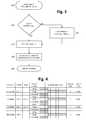
- Figure 3 illustrates, via a simplified flowchart, a possible process of setting of one of the automatic cooking programs, for example the program K, in the case of a user interface provided with the selectors S1 and S2.
- Block 100 is the starting block, via which the control system checks whether the knob S1 is in the position K.
- Control then passes to block 110, which is a test block, via which the system checks whether the selector S2 is in the position S2 0 .
- Block 120 hence enables execution of the program K.
- Start of execution preferably takes place automatically, when the selector S1 is in the position corresponding to one of the automatic cooking programs (i.e., to one of the programs J, K, or L) and the selector S2 is in the position S2 0 .
- Selection and/or start of the automatic cooking program i.e., one of the programs J, K, or L is preferably represented graphically also on the display 13.
- Control then passes to block 140, which represents the end of the program K previously selected, which may possibly be notified via a visual indication (for example, on the display 13) and/or an acoustic warning.
- the control system then sets itself in an END or quiescence state.
- Control then passes to block 150, of end-of-program, i.e., of end-of-cooking.
- any temperature selection made via the selector S2 or else via the various control means 13, 16-18, is rendered ineffective. Consequently, even in the case where the user turns the selector S2 into one of its operative selection positions, this action will have no effect on the pre-set temperature profile for the automatic program selected.
- the control system of the oven may be pre-arranged for omitting display of the menu for temperature selection, when an automatic program has been previously selected, or else for enabling display thereof but not access for the purposes of modification of temperature values.
- the user is free to perform other selections or actions that in any case do not affect the modes of management of the electrical loads envisaged for the automatic program, such as turning-off of the oven, for example by bringing the selector S1 into the corresponding inoperative or zero position or else by acting on the ON/OFF switch 15.
- the control system manages operation of at least one heating element internal to the oven and at least one heating element external to the oven, in particular the internal elements 8, 10 and the external element 11.
- the heating elements 8, 10 and 11 can be activated continuously, or else cyclically, i.e., with activation steps separated by de-activation pauses.
- control system is pre-arranged also for controlling in a differentiated way the speed of actuation of the extraction fan 7 in different operating steps of an automatic cooking program.
- This characteristic is particularly important in so far as it enables management of the level of moisture present within the cooking cavity and, in the last analysis, the amount of residual water present in the foods being cooked.
- various adjustment speeds are hence envisaged for the motor 7a of the fan 7, which are variously used in the course of various automatic cooking programs and/or in various single operating steps of one and the same automatic cooking program.
- the table below highlights, by way of example, six different levels of speed of the motor 7a, for each of which a generic r.p.m. range, a preferred r.p.m. range, and a preferred r.p.m. value are indicated.
- control system of the oven 1 is pre-arranged for setting automatically the r.p.m. of the motor 7a necessary in each operating step of an automatic cycle.
- control system is moreover pre-arranged for controlling operation also of the circulation fan 6, during execution of one or more operating steps of an automatic cooking cycle J-L.
- control system is pre-arranged for enabling operation at constant r.p.m. of the fan 6 during execution of a program J-L, but not excluded from the scope of the invention is the case of actuations of the corresponding motor 6a at different speeds, for execution of different automatic programs and/or execution of different steps of one and the same automatic cooking program.
- Figure 4 illustrates schematically, in tabular form, the possible development of an automatic operating program according to a possible embodiment of the invention, which in the example is a program dedicated to cooking of beef meat.
- the program which is assumed as being the program J, comprises:
- the second fixed time is longer than the first fixed time, and the first cooking temperature is higher than the second cooking temperature.
- the motor of the extraction fan 7 here referred to as "RADIAL FAN”
- the motor of the extraction fan 7 is driven in the pre-heating step at a higher r.p.m. than in the first cooking step and is driven in the second cooking step at a lower r.p.m. than in the first cooking step.
- the time necessary for execution of the pre-heating step is not exactly predetermined, in so far as its execution terminates when a given temperature is reached, which can be detected via the temperature sensor TS.
- the characteristics of the oven and of the heating elements are substantially known parameters, the time necessary for reaching the heating temperature envisaged for the pre-heating step is variable as a function of external factors, such as for example the temperature inside the cooking cavity CC, the amount of foods being cooked, the type of containers for the foods (metal, ceramic, glass, etc.).
- the total duration of the program J is defined herein as being “substantially pre-set”.
- the pre-heating step may have a duration comprised between 3 and 8 minutes, when the program is started with the oven cold.
- the program J may be started also with the inside of the cavity CC already relatively hot, for example following upon a previous cooking operation: in this case, hence, the duration of the pre-heating step will be shorter, for example between 2 and 5 minutes.
- the heating temperature that must be reached at the end of the pre-heating step is comprised between 190°C and 230°C, very preferably between 200°C and 220°C
- the first cooking temperature is preferably comprised between 210°C and 250°C, very preferably between 220°C and 240°C
- the second cooking temperature is preferably comprised between 140°C and 180°C, very preferably between 150°C and 170°C.
- the aforesaid three substantially pre-set temperatures are 210°C, 235°C, and 160°C, respectively.
- the first cooking step has a duration comprised between 5 and 15 minutes, whereas the second cooking step has a duration comprised between 30 and 50 minutes.
- these durations are 10 and 35 minutes, respectively.
- the heating elements 8, 10 and 11 are activated cyclically.
- the squares appearing in the section "ACTIVATION CYCLE” each correspond to a time of 12 seconds, with a total duty cycle of 2 minutes (10 squares x 12 seconds).
- the heating elements 8 and 11 are first activated, and then just the heating element 10 (“GRILL”) is activated.
- the duration of activation of the elements 8 and 11 (36 seconds) is shorter than the duration of activation of the element 10 (84 seconds). Similar profiles of activation of the resistances 8, 10 and 11 are followed also in the two subsequent cooking steps.
- the fan 7 is preferably brought to the speed "6" in the pre-heating step, to the speed "5" in the first cooking step, and to the speed "1" in the second cooking step.
- the fan 6 here referred to as "CAVITY FAN”
- CAVITY FAN is moreover preferably active, at its maximum speed, or in any case at a speed that is indicatively comprised between 1200 and 1350 r.p.m.
- the program J may further comprise a final heat-recovery step, during which the heating elements are controlled so as to obtain a drop of the temperature inside the cooking cavity CC to a value comprised between 40°C and 60°C and then maintain this temperature up to the end of the program.
- the extraction fan 7 is preferably active at the speed "2". Also the fan 6 is preferably active.
- the program J has a total duration of approximately 55 minutes.
- the duration of the pre-heating step is variable: for this reason, also the recovery step preferably has a variable duration, in particular a duration that is determined each time by the control system and that corresponds to the difference between the pre-set duration of 55 minutes and the sum of the duration of the pre-heating step and of the two cooking steps.
- Figure 5 illustrates schematically, in tabular form, the possible development of another automatic operating program according to a possible embodiment of the invention, which in the example is a program dedicated to baking brioche buns. Also in this example, the program in question, which is assumed as being the program K, comprises:
- the second fixed time is shorter than the first fixed time, whereas the first and second cooking temperatures are the same.
- the motor of the extraction fan 7 (“RADIAL FAN") is inactive in the pre-heating step, whereas in the second cooking step it is driven at an r.p.m. higher than in the first cooking step.
- the time necessary for execution of the pre-heating step is slightly variable, in so far as its execution terminates when a given temperature, which may be detected via the temperature sensor TS, is reached.
- the pre-heating step may have a duration comprised between 2 and 6 minutes.
- the program K is preferably to be started with the inside of the cavity CC at ambient temperature.
- the heating temperature that is to be reached at the end of the pre-heating step is comprised between 100°C and 140°C, very preferably between 110°C and 130°C, whereas the first and second cooking temperatures are preferably comprised between 150°C and 190°C, very preferably between 160°C and 180°C.
- the aforesaid substantially pre-set temperatures are 120°C and 170°C, respectively.
- the first cooking step has a duration comprised between 15 and 35 minutes, whereas the second cooking step has a duration comprised between 5 and 15 minutes.
- these durations are 25 and 10 minutes, respectively.
- the heating elements 8 and 11 are both active in the pre-heating step, the element 11 being activated cyclically and the element 8 being active continuously. In the two subsequent cooking steps, just the element 8 is active continuously.
- the fan 7 is inactive in the pre-heating step so as to be brought to the speed "1" in the first cooking step and then to the speed "6" in the second cooking step.
- the fan 6 (“CAVITY FAN”) is preferably active at its maximum speed, or in any case at a speed that is indicatively comprised between 1200 and 1350 r.p.m..
- the program K may further comprise a final heat-recovery step.
- the heating elements are inactive so as to obtain a natural drop in temperature in the cavity CC.
- the recovery step has a fixed duration, herein of 5 minutes.
- the extraction fan 7 is preferably active at the speed "6". Also the fan 6 is preferably active.
- the fan 7 is inactive and/or driven at a relatively low r.p.m. in the two first operating steps of the program K in order to reduce removal of moisture from the food being cooked and hence prevent early drying thereof.
- the product has in any case assumed the necessary outer consistency, removal of the residual moisture is exalted via a sharp increase of the r.p.m. of the fan 7.
- the program K has a total duration of approximately 45 minutes, slightly variable as a function of the duration of the pre-heating step.
- Figure 6 illustrates schematically, in tabular form, the possible development of a further automatic operating program according to a possible embodiment of the invention, which in the example is a program dedicated to baking of bread.
- the program in question which is assumed as being the program L, comprises four operating cooking steps, in each of which the inside of the cooking cavity CC is brought to a respective substantially pre-set cooking temperature and kept at said temperature for a respective substantially fixed time.
- the fixed time of execution of the third step is longer than that of the first step and of the second step, the first and second steps preferably having the same duration; the fixed time of the fourth step is, instead, shorter than that of the third step and longer than that of the first and second steps.
- the temperatures increase in the first three steps, i.e., the temperature of the first step is lower than the temperature of the second step, which is in turn lower than the temperature of the third step.
- the temperature of the fourth step is higher than the temperature of the first two steps, but lower than the temperature of the third step.
- the motor of the extraction fan 7 (“RADIAL FAN”) is inactive in the first cooking step, whereas in the third cooking step it is driven at an r.p.m. higher than in the second cooking step. In the fourth cooking step, the fan 7 is brought to an r.p.m. higher than in the third step.
- the program L is preferably designed to be started with the inside of the cavity CC at ambient temperature.
- the temperature in the first cooking step is comprised between 40°C and 80°C, very preferably between 50°C and 70°C
- the temperature in the second cooking step is comprised between 80°C and 120°C, very preferably between 90°C and 110°C
- the temperature in the third cooking step is comprised between 200°C and 240°C, very preferably between 210°C and 230°C
- the temperature in the fourth cooking step is comprised between 190°C and 230°C, very preferably between 200°C and 220°C.
- the aforesaid substantially pre-set temperatures are 60°C, 100°C, 220°C, and 210°C.
- the first and second cooking steps each have a duration comprised between 5 and 15 minutes
- the third cooking step has a duration comprised between 15 and 35 minutes
- the fourth cooking step has a duration comprised between 5 and 15 minutes.
- the durations of the four steps are 10, 10, 23 and 12 minutes, respectively.
- just the heating element 10 (“GRILL”) is active, continuously, in the first cooking step, whereas in the second cooking step all the heating elements 8, 10 and 11 are activated cyclically, the pauses of de-activation of the element 10 (“GRILL”) having a duration longer than the pauses of de-activation of the element 11 (“SOLE”).
- the pauses of de-activation of the element 8 (“CIRCULAR”) have, instead, a duration shorter than the pauses of de-activation of the elements 10 and 11.
- the elements 8 and 10 are activated cyclically, with the pauses of de-activation of the element 8 (“CIRCULAR") that have a duration longer than the pauses of de-activation of the element 10 (“GRILL").
- the pauses of de-activation of the element 8 have, in the third step, a duration longer than in the second step; on the other hand, in the third step, the de-activation pauses of the element 10 have a duration shorter than in the second step.
- the elements 8 and 10 are cyclically activated, with the pauses of de-activation of the element 8 (“CIRCULAR") that have a duration longer than the pauses of de-activation of the element 10 (“GRILL").
- the pauses of de-activation of the element 8 have, in the fourth step, a duration longer than in the third step; on the other hand, in the fourth step, the pauses of de-activation of the element 10 have a duration shorter than in the third step.
- the fan 7 is inactive in the first cooking step and is then brought to the speed "1" in the second cooking step, to the speed "2" in the third cooking step, and to the speed "6” in the fourth cooking step.
- the fan 6 (“CAVITY FAN”) is preferably active at its maximum speed, or in any case at a speed that is indicatively comprised between 1200 and 1350 r.p.m.
- the program L may further comprise a final heat-recovery step.
- the heating elements are inactive so as to obtain a natural drop in temperature in the cavity CC.
- the recovery step has a fixed duration, here of 5 minutes.
- the extraction fan 7 is preferably active, at the speed "6". Also the fan 6 is preferably active.
- the program L has a total duration of approximately 60 minutes.
- the modes of selection of the automatic programs are simple and intuitive, virtually eliminating any risk of errors of setting, at the same time preventing the possibility of the user inadvertently modifying the pre-set temperature profile for that program and/or its duration.
Landscapes
- Engineering & Computer Science (AREA)
- Chemical & Material Sciences (AREA)
- Combustion & Propulsion (AREA)
- Mechanical Engineering (AREA)
- General Engineering & Computer Science (AREA)
- Electric Stoves And Ranges (AREA)
Priority Applications (1)
| Application Number | Priority Date | Filing Date | Title |
|---|---|---|---|
| EP15178519.3A EP3124873A1 (fr) | 2015-07-27 | 2015-07-27 | Four de cuisson domestique |
Applications Claiming Priority (1)
| Application Number | Priority Date | Filing Date | Title |
|---|---|---|---|
| EP15178519.3A EP3124873A1 (fr) | 2015-07-27 | 2015-07-27 | Four de cuisson domestique |
Publications (1)
| Publication Number | Publication Date |
|---|---|
| EP3124873A1 true EP3124873A1 (fr) | 2017-02-01 |
Family
ID=54106102
Family Applications (1)
| Application Number | Title | Priority Date | Filing Date |
|---|---|---|---|
| EP15178519.3A Withdrawn EP3124873A1 (fr) | 2015-07-27 | 2015-07-27 | Four de cuisson domestique |
Country Status (1)
| Country | Link |
|---|---|
| EP (1) | EP3124873A1 (fr) |
Cited By (2)
| Publication number | Priority date | Publication date | Assignee | Title |
|---|---|---|---|---|
| US10721948B1 (en) | 2017-02-08 | 2020-07-28 | Electrolux Home Products, Inc. | Air sous-vide |
| WO2024161131A1 (fr) * | 2023-01-30 | 2024-08-08 | Ooni Limited | Procédé de cuisson à l'aide d'un appareil de cuisson, dispositif de commande et appareil de cuisson |
Citations (3)
| Publication number | Priority date | Publication date | Assignee | Title |
|---|---|---|---|---|
| DE10021235A1 (de) * | 2000-04-29 | 2001-10-31 | Aeg Hausgeraete Gmbh | Haushaltsbackofen mit Räucherfunktion |
| DE102006044039B3 (de) * | 2006-09-14 | 2007-12-27 | Miele & Cie. Kg | Verfahren zur Regelung des Abluftvolumenstroms aus einem Garraum eines Backofens |
| CH705766A2 (de) * | 2013-03-07 | 2013-04-30 | V Zug Ag | Backofen mit klimagesteuerter Temperaturbegrenzung. |
-
2015
- 2015-07-27 EP EP15178519.3A patent/EP3124873A1/fr not_active Withdrawn
Patent Citations (3)
| Publication number | Priority date | Publication date | Assignee | Title |
|---|---|---|---|---|
| DE10021235A1 (de) * | 2000-04-29 | 2001-10-31 | Aeg Hausgeraete Gmbh | Haushaltsbackofen mit Räucherfunktion |
| DE102006044039B3 (de) * | 2006-09-14 | 2007-12-27 | Miele & Cie. Kg | Verfahren zur Regelung des Abluftvolumenstroms aus einem Garraum eines Backofens |
| CH705766A2 (de) * | 2013-03-07 | 2013-04-30 | V Zug Ag | Backofen mit klimagesteuerter Temperaturbegrenzung. |
Cited By (3)
| Publication number | Priority date | Publication date | Assignee | Title |
|---|---|---|---|---|
| US10721948B1 (en) | 2017-02-08 | 2020-07-28 | Electrolux Home Products, Inc. | Air sous-vide |
| US11457651B1 (en) | 2017-02-08 | 2022-10-04 | Electrolux Home Products, Inc. | Air sous-vide |
| WO2024161131A1 (fr) * | 2023-01-30 | 2024-08-08 | Ooni Limited | Procédé de cuisson à l'aide d'un appareil de cuisson, dispositif de commande et appareil de cuisson |
Similar Documents
| Publication | Publication Date | Title |
|---|---|---|
| US11602149B2 (en) | Food preparation apparatus and methods | |
| US12232648B2 (en) | Toaster and convection oven with variable controls | |
| US8674270B2 (en) | Cooking appliance with programmable recipe system | |
| EP2710303B1 (fr) | Four à cuisson combinée doté d'un contrôle de l'humidité convivial pour l'opérateur | |
| US7378620B2 (en) | Oven control system | |
| EP2739191B1 (fr) | Procédés et appareil de commande de cuisson intuitive | |
| US9756981B2 (en) | Toaster oven | |
| US9057526B2 (en) | Programmable cooking appliance | |
| KR20060110746A (ko) | 스팀을 사용하여 디저트를 굽는 방법 | |
| EP3124873A1 (fr) | Four de cuisson domestique | |
| WO2015164875A1 (fr) | Dispositif et procédé de préparation d'aliments | |
| CN105996806A (zh) | 烤箱及烤箱的控制方法 | |
| EP3124872A1 (fr) | Four de cuisson domestique | |
| JP4799608B2 (ja) | 加熱調理器 | |
| JP6157913B2 (ja) | 加熱調理器 | |
| JP4282491B2 (ja) | 加熱調理器 | |
| JP4813535B2 (ja) | 加熱調理器 | |
| WO2006051409A1 (fr) | Procede de cuisson de masse de pate contenant du levain et four adapte a cette cuisson | |
| JP2011185595A (ja) | 加熱調理装置 | |
| KR20060115331A (ko) | 스팀 오븐에서 조리된 음식을 유지하기 위한 방법 | |
| KR101274393B1 (ko) | 전기 오븐 및 그 제어 방법 | |
| JP6088899B2 (ja) | 加熱調理器 | |
| JP2001235154A (ja) | 加熱調理装置 | |
| CN114680658A (zh) | 一种烤箱和烤箱开门烤控制方法 | |
| JP2010194021A (ja) | 自動製パン機 |
Legal Events
| Date | Code | Title | Description |
|---|---|---|---|
| PUAI | Public reference made under article 153(3) epc to a published international application that has entered the european phase |
Free format text: ORIGINAL CODE: 0009012 |
|
| AK | Designated contracting states |
Kind code of ref document: A1 Designated state(s): AL AT BE BG CH CY CZ DE DK EE ES FI FR GB GR HR HU IE IS IT LI LT LU LV MC MK MT NL NO PL PT RO RS SE SI SK SM TR |
|
| AX | Request for extension of the european patent |
Extension state: BA ME |
|
| RAP1 | Party data changed (applicant data changed or rights of an application transferred) |
Owner name: WHIRLPOOL EMEA S.P.A |
|
| STAA | Information on the status of an ep patent application or granted ep patent |
Free format text: STATUS: THE APPLICATION IS DEEMED TO BE WITHDRAWN |
|
| 18D | Application deemed to be withdrawn |
Effective date: 20170802 |