EP3124902A1 - Installation de décomposition de l'air, procédé de fonctionnement et dispositif de commande - Google Patents
Installation de décomposition de l'air, procédé de fonctionnement et dispositif de commande Download PDFInfo
- Publication number
- EP3124902A1 EP3124902A1 EP16001509.5A EP16001509A EP3124902A1 EP 3124902 A1 EP3124902 A1 EP 3124902A1 EP 16001509 A EP16001509 A EP 16001509A EP 3124902 A1 EP3124902 A1 EP 3124902A1
- Authority
- EP
- European Patent Office
- Prior art keywords
- cooling
- air
- recooling
- plant
- cooling water
- Prior art date
- Legal status (The legal status is an assumption and is not a legal conclusion. Google has not performed a legal analysis and makes no representation as to the accuracy of the status listed.)
- Withdrawn
Links
- 238000000926 separation method Methods 0.000 title claims abstract description 53
- 238000011017 operating method Methods 0.000 title abstract 2
- 238000001816 cooling Methods 0.000 claims abstract description 84
- 239000000498 cooling water Substances 0.000 claims abstract description 54
- 238000000034 method Methods 0.000 claims description 17
- 239000007788 liquid Substances 0.000 claims description 6
- 238000009423 ventilation Methods 0.000 claims description 3
- 238000012856 packing Methods 0.000 claims description 2
- XLYOFNOQVPJJNP-UHFFFAOYSA-N water Substances O XLYOFNOQVPJJNP-UHFFFAOYSA-N 0.000 description 23
- 238000004821 distillation Methods 0.000 description 17
- IJGRMHOSHXDMSA-UHFFFAOYSA-N Atomic nitrogen Chemical compound N#N IJGRMHOSHXDMSA-UHFFFAOYSA-N 0.000 description 12
- 239000007789 gas Substances 0.000 description 7
- XKRFYHLGVUSROY-UHFFFAOYSA-N Argon Chemical compound [Ar] XKRFYHLGVUSROY-UHFFFAOYSA-N 0.000 description 6
- 238000013461 design Methods 0.000 description 6
- 229910052757 nitrogen Inorganic materials 0.000 description 6
- 230000008901 benefit Effects 0.000 description 5
- 230000001419 dependent effect Effects 0.000 description 5
- 230000008929 regeneration Effects 0.000 description 4
- 238000011069 regeneration method Methods 0.000 description 4
- 229910052786 argon Inorganic materials 0.000 description 3
- QVGXLLKOCUKJST-UHFFFAOYSA-N atomic oxygen Chemical compound [O] QVGXLLKOCUKJST-UHFFFAOYSA-N 0.000 description 3
- 230000006835 compression Effects 0.000 description 3
- 238000007906 compression Methods 0.000 description 3
- 238000010586 diagram Methods 0.000 description 3
- 230000007613 environmental effect Effects 0.000 description 3
- 238000001704 evaporation Methods 0.000 description 3
- 239000001301 oxygen Substances 0.000 description 3
- 229910052760 oxygen Inorganic materials 0.000 description 3
- 238000012545 processing Methods 0.000 description 3
- MYMOFIZGZYHOMD-UHFFFAOYSA-N Dioxygen Chemical compound O=O MYMOFIZGZYHOMD-UHFFFAOYSA-N 0.000 description 2
- 238000004458 analytical method Methods 0.000 description 2
- 230000000694 effects Effects 0.000 description 2
- MWRWFPQBGSZWNV-UHFFFAOYSA-N Dinitrosopentamethylenetetramine Chemical compound C1N2CN(N=O)CN1CN(N=O)C2 MWRWFPQBGSZWNV-UHFFFAOYSA-N 0.000 description 1
- 238000010521 absorption reaction Methods 0.000 description 1
- 238000004364 calculation method Methods 0.000 description 1
- 229940112112 capex Drugs 0.000 description 1
- 230000005611 electricity Effects 0.000 description 1
- 230000008020 evaporation Effects 0.000 description 1
- FEBLZLNTKCEFIT-VSXGLTOVSA-N fluocinolone acetonide Chemical compound C1([C@@H](F)C2)=CC(=O)C=C[C@]1(C)[C@]1(F)[C@@H]2[C@@H]2C[C@H]3OC(C)(C)O[C@@]3(C(=O)CO)[C@@]2(C)C[C@@H]1O FEBLZLNTKCEFIT-VSXGLTOVSA-N 0.000 description 1
- 238000004508 fractional distillation Methods 0.000 description 1
- 238000010438 heat treatment Methods 0.000 description 1
- 229910052743 krypton Inorganic materials 0.000 description 1
- DNNSSWSSYDEUBZ-UHFFFAOYSA-N krypton atom Chemical compound [Kr] DNNSSWSSYDEUBZ-UHFFFAOYSA-N 0.000 description 1
- 238000012423 maintenance Methods 0.000 description 1
- 238000004519 manufacturing process Methods 0.000 description 1
- DOTMOQHOJINYBL-UHFFFAOYSA-N molecular nitrogen;molecular oxygen Chemical compound N#N.O=O DOTMOQHOJINYBL-UHFFFAOYSA-N 0.000 description 1
- 229910052756 noble gas Inorganic materials 0.000 description 1
- 150000002835 noble gases Chemical class 0.000 description 1
- 230000008092 positive effect Effects 0.000 description 1
- 238000002360 preparation method Methods 0.000 description 1
- 238000011084 recovery Methods 0.000 description 1
- 238000005057 refrigeration Methods 0.000 description 1
- 230000009897 systematic effect Effects 0.000 description 1
- 238000011144 upstream manufacturing Methods 0.000 description 1
- 229910052724 xenon Inorganic materials 0.000 description 1
- FHNFHKCVQCLJFQ-UHFFFAOYSA-N xenon atom Chemical compound [Xe] FHNFHKCVQCLJFQ-UHFFFAOYSA-N 0.000 description 1
Images


Classifications
-
- F—MECHANICAL ENGINEERING; LIGHTING; HEATING; WEAPONS; BLASTING
- F25—REFRIGERATION OR COOLING; COMBINED HEATING AND REFRIGERATION SYSTEMS; HEAT PUMP SYSTEMS; MANUFACTURE OR STORAGE OF ICE; LIQUEFACTION SOLIDIFICATION OF GASES
- F25J—LIQUEFACTION, SOLIDIFICATION OR SEPARATION OF GASES OR GASEOUS OR LIQUEFIED GASEOUS MIXTURES BY PRESSURE AND COLD TREATMENT OR BY BRINGING THEM INTO THE SUPERCRITICAL STATE
- F25J3/00—Processes or apparatus for separating the constituents of gaseous or liquefied gaseous mixtures involving the use of liquefaction or solidification
- F25J3/02—Processes or apparatus for separating the constituents of gaseous or liquefied gaseous mixtures involving the use of liquefaction or solidification by rectification, i.e. by continuous interchange of heat and material between a vapour stream and a liquid stream
- F25J3/04—Processes or apparatus for separating the constituents of gaseous or liquefied gaseous mixtures involving the use of liquefaction or solidification by rectification, i.e. by continuous interchange of heat and material between a vapour stream and a liquid stream for air
- F25J3/04006—Providing pressurised feed air or process streams within or from the air fractionation unit
- F25J3/04012—Providing pressurised feed air or process streams within or from the air fractionation unit by compression of warm gaseous streams; details of intake or interstage cooling
- F25J3/04018—Providing pressurised feed air or process streams within or from the air fractionation unit by compression of warm gaseous streams; details of intake or interstage cooling of main feed air
-
- F—MECHANICAL ENGINEERING; LIGHTING; HEATING; WEAPONS; BLASTING
- F28—HEAT EXCHANGE IN GENERAL
- F28C—HEAT-EXCHANGE APPARATUS, NOT PROVIDED FOR IN ANOTHER SUBCLASS, IN WHICH THE HEAT-EXCHANGE MEDIA COME INTO DIRECT CONTACT WITHOUT CHEMICAL INTERACTION
- F28C3/00—Other direct-contact heat-exchange apparatus
- F28C3/06—Other direct-contact heat-exchange apparatus the heat-exchange media being a liquid and a gas or vapour
-
- F—MECHANICAL ENGINEERING; LIGHTING; HEATING; WEAPONS; BLASTING
- F25—REFRIGERATION OR COOLING; COMBINED HEATING AND REFRIGERATION SYSTEMS; HEAT PUMP SYSTEMS; MANUFACTURE OR STORAGE OF ICE; LIQUEFACTION SOLIDIFICATION OF GASES
- F25J—LIQUEFACTION, SOLIDIFICATION OR SEPARATION OF GASES OR GASEOUS OR LIQUEFIED GASEOUS MIXTURES BY PRESSURE AND COLD TREATMENT OR BY BRINGING THEM INTO THE SUPERCRITICAL STATE
- F25J3/00—Processes or apparatus for separating the constituents of gaseous or liquefied gaseous mixtures involving the use of liquefaction or solidification
- F25J3/02—Processes or apparatus for separating the constituents of gaseous or liquefied gaseous mixtures involving the use of liquefaction or solidification by rectification, i.e. by continuous interchange of heat and material between a vapour stream and a liquid stream
- F25J3/04—Processes or apparatus for separating the constituents of gaseous or liquefied gaseous mixtures involving the use of liquefaction or solidification by rectification, i.e. by continuous interchange of heat and material between a vapour stream and a liquid stream for air
- F25J3/04006—Providing pressurised feed air or process streams within or from the air fractionation unit
- F25J3/04012—Providing pressurised feed air or process streams within or from the air fractionation unit by compression of warm gaseous streams; details of intake or interstage cooling
- F25J3/04024—Providing pressurised feed air or process streams within or from the air fractionation unit by compression of warm gaseous streams; details of intake or interstage cooling of purified feed air, so-called boosted air
-
- F—MECHANICAL ENGINEERING; LIGHTING; HEATING; WEAPONS; BLASTING
- F25—REFRIGERATION OR COOLING; COMBINED HEATING AND REFRIGERATION SYSTEMS; HEAT PUMP SYSTEMS; MANUFACTURE OR STORAGE OF ICE; LIQUEFACTION SOLIDIFICATION OF GASES
- F25J—LIQUEFACTION, SOLIDIFICATION OR SEPARATION OF GASES OR GASEOUS OR LIQUEFIED GASEOUS MIXTURES BY PRESSURE AND COLD TREATMENT OR BY BRINGING THEM INTO THE SUPERCRITICAL STATE
- F25J3/00—Processes or apparatus for separating the constituents of gaseous or liquefied gaseous mixtures involving the use of liquefaction or solidification
- F25J3/02—Processes or apparatus for separating the constituents of gaseous or liquefied gaseous mixtures involving the use of liquefaction or solidification by rectification, i.e. by continuous interchange of heat and material between a vapour stream and a liquid stream
- F25J3/04—Processes or apparatus for separating the constituents of gaseous or liquefied gaseous mixtures involving the use of liquefaction or solidification by rectification, i.e. by continuous interchange of heat and material between a vapour stream and a liquid stream for air
- F25J3/04006—Providing pressurised feed air or process streams within or from the air fractionation unit
- F25J3/04109—Arrangements of compressors and /or their drivers
-
- F—MECHANICAL ENGINEERING; LIGHTING; HEATING; WEAPONS; BLASTING
- F25—REFRIGERATION OR COOLING; COMBINED HEATING AND REFRIGERATION SYSTEMS; HEAT PUMP SYSTEMS; MANUFACTURE OR STORAGE OF ICE; LIQUEFACTION SOLIDIFICATION OF GASES
- F25J—LIQUEFACTION, SOLIDIFICATION OR SEPARATION OF GASES OR GASEOUS OR LIQUEFIED GASEOUS MIXTURES BY PRESSURE AND COLD TREATMENT OR BY BRINGING THEM INTO THE SUPERCRITICAL STATE
- F25J3/00—Processes or apparatus for separating the constituents of gaseous or liquefied gaseous mixtures involving the use of liquefaction or solidification
- F25J3/02—Processes or apparatus for separating the constituents of gaseous or liquefied gaseous mixtures involving the use of liquefaction or solidification by rectification, i.e. by continuous interchange of heat and material between a vapour stream and a liquid stream
- F25J3/04—Processes or apparatus for separating the constituents of gaseous or liquefied gaseous mixtures involving the use of liquefaction or solidification by rectification, i.e. by continuous interchange of heat and material between a vapour stream and a liquid stream for air
- F25J3/04151—Purification and (pre-)cooling of the feed air; recuperative heat-exchange with product streams
- F25J3/04157—Afterstage cooling and so-called "pre-cooling" of the feed air upstream the air purification unit and main heat exchange line
-
- F—MECHANICAL ENGINEERING; LIGHTING; HEATING; WEAPONS; BLASTING
- F25—REFRIGERATION OR COOLING; COMBINED HEATING AND REFRIGERATION SYSTEMS; HEAT PUMP SYSTEMS; MANUFACTURE OR STORAGE OF ICE; LIQUEFACTION SOLIDIFICATION OF GASES
- F25J—LIQUEFACTION, SOLIDIFICATION OR SEPARATION OF GASES OR GASEOUS OR LIQUEFIED GASEOUS MIXTURES BY PRESSURE AND COLD TREATMENT OR BY BRINGING THEM INTO THE SUPERCRITICAL STATE
- F25J3/00—Processes or apparatus for separating the constituents of gaseous or liquefied gaseous mixtures involving the use of liquefaction or solidification
- F25J3/02—Processes or apparatus for separating the constituents of gaseous or liquefied gaseous mixtures involving the use of liquefaction or solidification by rectification, i.e. by continuous interchange of heat and material between a vapour stream and a liquid stream
- F25J3/04—Processes or apparatus for separating the constituents of gaseous or liquefied gaseous mixtures involving the use of liquefaction or solidification by rectification, i.e. by continuous interchange of heat and material between a vapour stream and a liquid stream for air
- F25J3/04406—Processes or apparatus for separating the constituents of gaseous or liquefied gaseous mixtures involving the use of liquefaction or solidification by rectification, i.e. by continuous interchange of heat and material between a vapour stream and a liquid stream for air using a dual pressure main column system
- F25J3/04412—Processes or apparatus for separating the constituents of gaseous or liquefied gaseous mixtures involving the use of liquefaction or solidification by rectification, i.e. by continuous interchange of heat and material between a vapour stream and a liquid stream for air using a dual pressure main column system in a classical double column flowsheet, i.e. with thermal coupling by a main reboiler-condenser in the bottom of low pressure respectively top of high pressure column
-
- F—MECHANICAL ENGINEERING; LIGHTING; HEATING; WEAPONS; BLASTING
- F25—REFRIGERATION OR COOLING; COMBINED HEATING AND REFRIGERATION SYSTEMS; HEAT PUMP SYSTEMS; MANUFACTURE OR STORAGE OF ICE; LIQUEFACTION SOLIDIFICATION OF GASES
- F25J—LIQUEFACTION, SOLIDIFICATION OR SEPARATION OF GASES OR GASEOUS OR LIQUEFIED GASEOUS MIXTURES BY PRESSURE AND COLD TREATMENT OR BY BRINGING THEM INTO THE SUPERCRITICAL STATE
- F25J3/00—Processes or apparatus for separating the constituents of gaseous or liquefied gaseous mixtures involving the use of liquefaction or solidification
- F25J3/02—Processes or apparatus for separating the constituents of gaseous or liquefied gaseous mixtures involving the use of liquefaction or solidification by rectification, i.e. by continuous interchange of heat and material between a vapour stream and a liquid stream
- F25J3/04—Processes or apparatus for separating the constituents of gaseous or liquefied gaseous mixtures involving the use of liquefaction or solidification by rectification, i.e. by continuous interchange of heat and material between a vapour stream and a liquid stream for air
- F25J3/04436—Processes or apparatus for separating the constituents of gaseous or liquefied gaseous mixtures involving the use of liquefaction or solidification by rectification, i.e. by continuous interchange of heat and material between a vapour stream and a liquid stream for air using at least a triple pressure main column system
- F25J3/04454—Processes or apparatus for separating the constituents of gaseous or liquefied gaseous mixtures involving the use of liquefaction or solidification by rectification, i.e. by continuous interchange of heat and material between a vapour stream and a liquid stream for air using at least a triple pressure main column system a main column system not otherwise provided, e.g. serially coupling of columns or more than three pressure levels
-
- F—MECHANICAL ENGINEERING; LIGHTING; HEATING; WEAPONS; BLASTING
- F25—REFRIGERATION OR COOLING; COMBINED HEATING AND REFRIGERATION SYSTEMS; HEAT PUMP SYSTEMS; MANUFACTURE OR STORAGE OF ICE; LIQUEFACTION SOLIDIFICATION OF GASES
- F25J—LIQUEFACTION, SOLIDIFICATION OR SEPARATION OF GASES OR GASEOUS OR LIQUEFIED GASEOUS MIXTURES BY PRESSURE AND COLD TREATMENT OR BY BRINGING THEM INTO THE SUPERCRITICAL STATE
- F25J3/00—Processes or apparatus for separating the constituents of gaseous or liquefied gaseous mixtures involving the use of liquefaction or solidification
- F25J3/02—Processes or apparatus for separating the constituents of gaseous or liquefied gaseous mixtures involving the use of liquefaction or solidification by rectification, i.e. by continuous interchange of heat and material between a vapour stream and a liquid stream
- F25J3/04—Processes or apparatus for separating the constituents of gaseous or liquefied gaseous mixtures involving the use of liquefaction or solidification by rectification, i.e. by continuous interchange of heat and material between a vapour stream and a liquid stream for air
- F25J3/04642—Recovering noble gases from air
- F25J3/04648—Recovering noble gases from air argon
- F25J3/04721—Producing pure argon, e.g. recovered from a crude argon column
-
- F—MECHANICAL ENGINEERING; LIGHTING; HEATING; WEAPONS; BLASTING
- F25—REFRIGERATION OR COOLING; COMBINED HEATING AND REFRIGERATION SYSTEMS; HEAT PUMP SYSTEMS; MANUFACTURE OR STORAGE OF ICE; LIQUEFACTION SOLIDIFICATION OF GASES
- F25J—LIQUEFACTION, SOLIDIFICATION OR SEPARATION OF GASES OR GASEOUS OR LIQUEFIED GASEOUS MIXTURES BY PRESSURE AND COLD TREATMENT OR BY BRINGING THEM INTO THE SUPERCRITICAL STATE
- F25J3/00—Processes or apparatus for separating the constituents of gaseous or liquefied gaseous mixtures involving the use of liquefaction or solidification
- F25J3/02—Processes or apparatus for separating the constituents of gaseous or liquefied gaseous mixtures involving the use of liquefaction or solidification by rectification, i.e. by continuous interchange of heat and material between a vapour stream and a liquid stream
- F25J3/04—Processes or apparatus for separating the constituents of gaseous or liquefied gaseous mixtures involving the use of liquefaction or solidification by rectification, i.e. by continuous interchange of heat and material between a vapour stream and a liquid stream for air
- F25J3/04763—Start-up or control of the process; Details of the apparatus used
- F25J3/04769—Operation, control and regulation of the process; Instrumentation within the process
- F25J3/04775—Air purification and pre-cooling
-
- F—MECHANICAL ENGINEERING; LIGHTING; HEATING; WEAPONS; BLASTING
- F25—REFRIGERATION OR COOLING; COMBINED HEATING AND REFRIGERATION SYSTEMS; HEAT PUMP SYSTEMS; MANUFACTURE OR STORAGE OF ICE; LIQUEFACTION SOLIDIFICATION OF GASES
- F25J—LIQUEFACTION, SOLIDIFICATION OR SEPARATION OF GASES OR GASEOUS OR LIQUEFIED GASEOUS MIXTURES BY PRESSURE AND COLD TREATMENT OR BY BRINGING THEM INTO THE SUPERCRITICAL STATE
- F25J3/00—Processes or apparatus for separating the constituents of gaseous or liquefied gaseous mixtures involving the use of liquefaction or solidification
- F25J3/02—Processes or apparatus for separating the constituents of gaseous or liquefied gaseous mixtures involving the use of liquefaction or solidification by rectification, i.e. by continuous interchange of heat and material between a vapour stream and a liquid stream
- F25J3/04—Processes or apparatus for separating the constituents of gaseous or liquefied gaseous mixtures involving the use of liquefaction or solidification by rectification, i.e. by continuous interchange of heat and material between a vapour stream and a liquid stream for air
- F25J3/04763—Start-up or control of the process; Details of the apparatus used
- F25J3/04769—Operation, control and regulation of the process; Instrumentation within the process
- F25J3/04793—Rectification, e.g. columns; Reboiler-condenser
- F25J3/048—Argon recovery
- F25J3/04806—High purity argon purification
-
- F—MECHANICAL ENGINEERING; LIGHTING; HEATING; WEAPONS; BLASTING
- F28—HEAT EXCHANGE IN GENERAL
- F28C—HEAT-EXCHANGE APPARATUS, NOT PROVIDED FOR IN ANOTHER SUBCLASS, IN WHICH THE HEAT-EXCHANGE MEDIA COME INTO DIRECT CONTACT WITHOUT CHEMICAL INTERACTION
- F28C1/00—Direct-contact trickle coolers, e.g. cooling towers
-
- F—MECHANICAL ENGINEERING; LIGHTING; HEATING; WEAPONS; BLASTING
- F25—REFRIGERATION OR COOLING; COMBINED HEATING AND REFRIGERATION SYSTEMS; HEAT PUMP SYSTEMS; MANUFACTURE OR STORAGE OF ICE; LIQUEFACTION SOLIDIFICATION OF GASES
- F25J—LIQUEFACTION, SOLIDIFICATION OR SEPARATION OF GASES OR GASEOUS OR LIQUEFIED GASEOUS MIXTURES BY PRESSURE AND COLD TREATMENT OR BY BRINGING THEM INTO THE SUPERCRITICAL STATE
- F25J2205/00—Processes or apparatus using other separation and/or other processing means
- F25J2205/30—Processes or apparatus using other separation and/or other processing means using a washing, e.g. "scrubbing" or bubble column for purification purposes
- F25J2205/32—Processes or apparatus using other separation and/or other processing means using a washing, e.g. "scrubbing" or bubble column for purification purposes as direct contact cooling tower to produce a cooled gas stream, e.g. direct contact after cooler [DCAC]
-
- F—MECHANICAL ENGINEERING; LIGHTING; HEATING; WEAPONS; BLASTING
- F25—REFRIGERATION OR COOLING; COMBINED HEATING AND REFRIGERATION SYSTEMS; HEAT PUMP SYSTEMS; MANUFACTURE OR STORAGE OF ICE; LIQUEFACTION SOLIDIFICATION OF GASES
- F25J—LIQUEFACTION, SOLIDIFICATION OR SEPARATION OF GASES OR GASEOUS OR LIQUEFIED GASEOUS MIXTURES BY PRESSURE AND COLD TREATMENT OR BY BRINGING THEM INTO THE SUPERCRITICAL STATE
- F25J2205/00—Processes or apparatus using other separation and/or other processing means
- F25J2205/30—Processes or apparatus using other separation and/or other processing means using a washing, e.g. "scrubbing" or bubble column for purification purposes
- F25J2205/34—Processes or apparatus using other separation and/or other processing means using a washing, e.g. "scrubbing" or bubble column for purification purposes as evaporative cooling tower to produce chilled water, e.g. evaporative water chiller [EWC]
-
- F—MECHANICAL ENGINEERING; LIGHTING; HEATING; WEAPONS; BLASTING
- F25—REFRIGERATION OR COOLING; COMBINED HEATING AND REFRIGERATION SYSTEMS; HEAT PUMP SYSTEMS; MANUFACTURE OR STORAGE OF ICE; LIQUEFACTION SOLIDIFICATION OF GASES
- F25J—LIQUEFACTION, SOLIDIFICATION OR SEPARATION OF GASES OR GASEOUS OR LIQUEFIED GASEOUS MIXTURES BY PRESSURE AND COLD TREATMENT OR BY BRINGING THEM INTO THE SUPERCRITICAL STATE
- F25J2205/00—Processes or apparatus using other separation and/or other processing means
- F25J2205/60—Processes or apparatus using other separation and/or other processing means using adsorption on solid adsorbents, e.g. by temperature-swing adsorption [TSA] at the hot or cold end
- F25J2205/62—Purifying more than one feed stream in multiple adsorption vessels, e.g. for two feed streams at different pressures
-
- F—MECHANICAL ENGINEERING; LIGHTING; HEATING; WEAPONS; BLASTING
- F25—REFRIGERATION OR COOLING; COMBINED HEATING AND REFRIGERATION SYSTEMS; HEAT PUMP SYSTEMS; MANUFACTURE OR STORAGE OF ICE; LIQUEFACTION SOLIDIFICATION OF GASES
- F25J—LIQUEFACTION, SOLIDIFICATION OR SEPARATION OF GASES OR GASEOUS OR LIQUEFIED GASEOUS MIXTURES BY PRESSURE AND COLD TREATMENT OR BY BRINGING THEM INTO THE SUPERCRITICAL STATE
- F25J2205/00—Processes or apparatus using other separation and/or other processing means
- F25J2205/60—Processes or apparatus using other separation and/or other processing means using adsorption on solid adsorbents, e.g. by temperature-swing adsorption [TSA] at the hot or cold end
- F25J2205/66—Regenerating the adsorption vessel, e.g. kind of reactivation gas
- F25J2205/70—Heating the adsorption vessel
-
- F—MECHANICAL ENGINEERING; LIGHTING; HEATING; WEAPONS; BLASTING
- F25—REFRIGERATION OR COOLING; COMBINED HEATING AND REFRIGERATION SYSTEMS; HEAT PUMP SYSTEMS; MANUFACTURE OR STORAGE OF ICE; LIQUEFACTION SOLIDIFICATION OF GASES
- F25J—LIQUEFACTION, SOLIDIFICATION OR SEPARATION OF GASES OR GASEOUS OR LIQUEFIED GASEOUS MIXTURES BY PRESSURE AND COLD TREATMENT OR BY BRINGING THEM INTO THE SUPERCRITICAL STATE
- F25J2205/00—Processes or apparatus using other separation and/or other processing means
- F25J2205/84—Processes or apparatus using other separation and/or other processing means using filter
-
- F—MECHANICAL ENGINEERING; LIGHTING; HEATING; WEAPONS; BLASTING
- F25—REFRIGERATION OR COOLING; COMBINED HEATING AND REFRIGERATION SYSTEMS; HEAT PUMP SYSTEMS; MANUFACTURE OR STORAGE OF ICE; LIQUEFACTION SOLIDIFICATION OF GASES
- F25J—LIQUEFACTION, SOLIDIFICATION OR SEPARATION OF GASES OR GASEOUS OR LIQUEFIED GASEOUS MIXTURES BY PRESSURE AND COLD TREATMENT OR BY BRINGING THEM INTO THE SUPERCRITICAL STATE
- F25J2210/00—Processes characterised by the type or other details of the feed stream
- F25J2210/40—Air or oxygen enriched air, i.e. generally less than 30mol% of O2
-
- F—MECHANICAL ENGINEERING; LIGHTING; HEATING; WEAPONS; BLASTING
- F25—REFRIGERATION OR COOLING; COMBINED HEATING AND REFRIGERATION SYSTEMS; HEAT PUMP SYSTEMS; MANUFACTURE OR STORAGE OF ICE; LIQUEFACTION SOLIDIFICATION OF GASES
- F25J—LIQUEFACTION, SOLIDIFICATION OR SEPARATION OF GASES OR GASEOUS OR LIQUEFIED GASEOUS MIXTURES BY PRESSURE AND COLD TREATMENT OR BY BRINGING THEM INTO THE SUPERCRITICAL STATE
- F25J2270/00—Refrigeration techniques used
- F25J2270/90—External refrigeration, e.g. conventional closed-loop mechanical refrigeration unit using Freon or NH3, unspecified external refrigeration
-
- F—MECHANICAL ENGINEERING; LIGHTING; HEATING; WEAPONS; BLASTING
- F25—REFRIGERATION OR COOLING; COMBINED HEATING AND REFRIGERATION SYSTEMS; HEAT PUMP SYSTEMS; MANUFACTURE OR STORAGE OF ICE; LIQUEFACTION SOLIDIFICATION OF GASES
- F25J—LIQUEFACTION, SOLIDIFICATION OR SEPARATION OF GASES OR GASEOUS OR LIQUEFIED GASEOUS MIXTURES BY PRESSURE AND COLD TREATMENT OR BY BRINGING THEM INTO THE SUPERCRITICAL STATE
- F25J2290/00—Other details not covered by groups F25J2200/00 - F25J2280/00
- F25J2290/12—Particular process parameters like pressure, temperature, ratios
Definitions
- the invention relates to an air separation plant, a method for operating an air separation plant and a control device for such an air separation plant according to the respective preambles of the independent claims.
- cryogenic separation of air in air separation plants is known and, for example at H.-W. Haring (ed.), Industrial Gases Processing, Wiley-VCH, 2006, especially Section 2.2.5, "Cryogenic Rectification
- the present invention is suitable for different embodiments of corresponding air separation plants.
- Air separation plants have distillation column systems which can be designed, for example, as two-column systems, in particular as classic Linde double-column systems, but also as three-column or multi-column systems.
- distillation columns for the recovery of nitrogen and / or oxygen in the liquid and / or gaseous state for example, liquid oxygen, LOX, gaseous oxygen, GOX, liquid nitrogen, LIN and / or gaseous nitrogen, GAN
- distillation columns for nitrogen-oxygen Separation distillation columns can be provided for obtaining further air components, in particular the noble gases krypton, xenon and / or argon.
- the distillation column systems of air separation plants are operated at different operating pressures in their distillation columns.
- Known double column systems have, for example, a so-called (high) pressure column and a so-called low-pressure column.
- the operating pressure of the high-pressure column is, for example, 4.3 to 6.9 bar, in particular about 5.5 bar.
- the low-pressure column is operated at an operating pressure of, for example, 1.2 to 1.7 bar, in particular about 1.4 bar.
- the pressures stated here are absolute pressures in Bottom of corresponding distillation columns.
- the pressures mentioned below are also referred to as "distillation pressures" because they are subjected to the fractional distillation of the respectively fed air within the distillation columns. This does not exclude that other pressures may be present elsewhere in a distillation column system.
- feed air cooled compressed air
- air compressors for example, main air compressors and booster
- All air compressors can be multi-stage. Since about 95% of the energy demand in an air separation plant is created by the air compressors mentioned, the greatest potential for saving is present here. There is a general need for more energy efficient processes and systems for the cryogenic separation of air.
- the present invention provides an air separation plant, a method for operating an air separation plant and a control device for such an air separation plant with the respective features of the independent claims.
- Embodiments of the invention are the subject of the dependent claims and the following description.
- the feed air pressurized in the air compressors of an air separation plant is typically recooled in various cooling devices to remove the heat of compression generated during the compression.
- These cooling devices include, for example, intermediate and aftercoolers between and downstream of one or more compression stages, as known in the art.
- the recooling of the air compressed in a main air compressor of an air separation plant can take place, for example, inter alia in a direct contact cooler operated with cooling water from a cooling water circuit.
- indirect heat exchangers can be provided, which can also be operated with cooling water. Subsequently, the feed air is brought in known processes in a main heat exchanger to cryogenic temperatures, ie temperatures of well below 0 ° C.
- the recooling is in particular for the purpose of reducing the power consumption of the air compressor.
- the process air already enters the process of air separation colder, including in the main heat exchanger. Therefore, the heat to be transferred to the main heat exchanger is lower, which can therefore be carried out with a smaller volume and in addition less cold must be generated by relaxation.
- Refrigeration at correspondingly low temperature levels of, for example, 120 to 200 K results in considerable exergetic losses, which are significantly greater than in the cooling of cooling water, which occurs at near ambient temperature.
- larger-sized cryogenic components heat exchangers, turbines, valves
- Cooling water circuits of air separation plants typically include recooling plants in which the heated cooling water of the cooling water circuit is cooled by cooling air by evaporative cooling.
- cooling towers of known type can be used as recooling units, as also explained below.
- Corresponding air separation plants are for example in the EP 0 644 390 A1 and the JP 5 885093 A1 shown.
- the cooling air used in this case is typically derived from the environment of the air separation plant and therefore has a dependent on the environment temperature, a dependent on the environment pressure and a dependent on the environment moisture content. From these three parameters, the wet bulb temperature can be determined.
- the wet bulb temperature is a measure of the cooling limit temperature, ie the lowest temperature that the cooling water can theoretically achieve by direct evaporative cooling in a corresponding recooling plant.
- the cooling limit temperature is dependent on the relative humidity below the air temperature. The lower the temperature in the evaporative cooling, the drier the surrounding air is.
- the temperature difference actually reached in a corresponding recooling plant between the Wet bulb temperature and the cooled cooling water is referred to in the art as the cooling limit distance.
- the quality of a recooling plant for example a cooling tower, is determined by the specific packing surface, the ratio of liquid to gas and the pressure loss.
- a recooling plant for example a cooling tower
- the quality of a recooling plant is determined by the specific packing surface, the ratio of liquid to gas and the pressure loss.
- the used cooling distance is therefore based on economic considerations that include the above aspects.
- a cooling limit distance of 3 to 5 K is given as economical, see for example Z. K. Morvay & DD Gvozdenac, "Applied Industrial Energy and Environmental Management, Part III: Toolbox - Fundamentals for Analysis and Calculation of Energy and Environmental Performance, Toolbox 12: Cooling Towers", Chichester, Wiley, 2008 ,
- this information is conventionally given without mentioning the corresponding environmental conditions and the resulting wet bulb temperature.
- Recooling plants with a cooling limit distance of well below 3 K are technically feasible, but this is conventionally referred to as uneconomical.
- cooling boundary distances are conventionally used only on a laboratory scale, as for example according to the publication of VD Papaefthimiou et al., "Thermodynamic Study of Wet Cooling Tower Performance", Int. J. Energ. Res. 30 (6), 2006, 411-426 , the case.
- the cooling limit distance achievable by means of a recooling plant can be reliably predicted by the person skilled in the art on the basis of known calculation methods. is Therefore, the following is the speech that a recooling is designed such that it cools cooling water to a temperature which is a maximum temperature above the Feuchtkugeltemperatur, this is an instruction to those skilled in dimensioning a recooling such that it Has property, so has a corresponding cooling limit distance.
- the person skilled in the art will take appropriate account of the specific packing surface, the ratio of liquid to gas and the pressure loss.
- cooling limit distance below 3 K for a variety offers economic benefits from air separation plants.
- the cooling limit distance should be selected depending on the capital value (in monetary units per kW, net present value, NPV) for a given wet bulb temperature under design conditions. Systems with the same net present value can thus receive a recooling unit with the same amount of specific heat dissipated regardless of the respective ambient conditions. This allows a systematic selection of the cooling towers depending on the net present value.
- the present invention therefore proposes an air separation plant in which a cooling water circuit with a recooling plant is provided for cooling compressed air, wherein the recooling plant is adapted to cool cooling water using cooling air.
- the air separation plant according to the invention is characterized in that the recooling plant is set up to cool the cooling water to a temperature at least 3 K above that at least at a wet bulb temperature of the cooling air of more than 289 K Wet bulb temperature is.
- a cooling boundary distance of 3 K or less, in particular also 2 K or less or 1 K or less is achieved under the stated conditions.
- the efficiency of air separation plants can be markedly increased at medium and high wet bulb temperatures of more than 289 K as recognized and subsequently documented in accordance with the invention.
- the present invention is thus based on a substantial revaluation of the state of knowledge of cooling tower design with respect to air separation processes and cryogenic processes in general.
- a conventionally designed recooling plant can be designed in comparison with a recooling plant designed according to the invention Figures 2 and 3 to be viewed as.
- the recooling plant was assumed to be a (forced-ventilated) cooling tower with a water basin for receiving the return.
- a lower cooling limit temperature leads to a larger recooling plant with a likewise enlarged basin and thus to a higher investment price.
- the water mass flow is the same in both cases. It is crucial that in a large cooling tower with the same amount of cooling water, a larger amount of air can flow through the recooling, which absorbs the evaporating water and simultaneously allows a stronger convective cooling.
- a recooling unit is advantageously used which is designed such that it cools the cooling water to a temperature which is at least 0.5 K, for example but also at least 1 K, at least 1.5 K or at least 2 K above the wet bulb temperature is.
- a temperature which is at least 0.5 K, for example but also at least 1 K, at least 1.5 K or at least 2 K above the wet bulb temperature is.
- an air separation plant according to the invention can have an optionally designed recooling plant, but in particular this comprises a cooling tower.
- recooling or cooling towers with forced ventilation are often used in air separation plants and are proven and low maintenance.
- a cooling tower allows a comparatively simple reduction of the cooling limit temperature by enlargement, as explained above.
- the cooling water cooled using the recooling plant is suitable in particular for aftercooling downstream of compressors in a corresponding air separation plant, so that the cooling water circuit of an air separation plant according to the invention advantageously comprises a heat exchanger downstream of an air compressor or a stage of a corresponding air compressor.
- An "air compressor” is here understood to mean a single-stage or multi-stage arrangement which is set up to increase the pressure, in particular a radial or turbo compressor.
- One or more heat exchangers may be downstream of one or more compressor stages.
- a cooling zone width of the recooling plant can be in particular from 5 to 25 K, in particular from 8 to 12 K, typically about 10 K.
- the invention further extends to a method for operating an air separation plant, in which a cooling water circuit is provided with a recooling unit for cooling compressed air, wherein the recooling unit is adapted to cool cooling water using cooling air.
- the inventive method is characterized in that the recooling is operated such that it cools the cooling water to a temperature which is at most 3 K above the wet bulb temperature at least at a wet bulb temperature of the cooling air of more than 289 K.
- the present invention extends to a control device of an air separation plant, which is adapted to perform a corresponding method. In both cases reference should be made to the above explanations regarding features and advantages.
- FIG. 1 an air separation plant according to an embodiment of the invention is illustrated in the form of a schematic process flow diagram.
- cooling water temperatures and the corresponding wet bulb temperatures are shown to illustrate one embodiment of the invention.
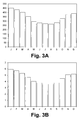
- FIGS. 3A and 3B are the present invention possible additional cooling of cooling water and the associated energy savings illustrated.
- FIG. 1 an air separation plant according to a particularly preferred embodiment of the invention is illustrated in the form of a schematic process flow diagram and denoted overall by 100.
- the air separation plant 100 is fed via a filter 101, a feed air stream a, compressed by a main air compressor 102 and cooled in a direct contact cooler 103, which among other things with a cooled water flow b from an evaporative cooler 104 is charged.
- the water flow b is thereby applied via a not separately designated pump to the direct contact cooler 103.
- water is supplied to the evaporative cooler 104 of a stream c, which can also be fed into the direct contact cooler 103 partially without prior cooling in the evaporative cooler 104.
- the direct contact cooler 103, a stream of water d is removed.
- the illustrated water flows b, c and d as well as the direct contact cooler 103 and the evaporative cooler 104 are incorporated into a cooling water circuit designated here by 10, which also contains any other water flows, not illustrated, Pumps, direct and indirect heat exchangers, etc. may include.
- the main air compressor 102 as illustrated here in a highly simplified manner, have at least two compressor stages 1 and 2, between which an intermediate cooling takes place by means of an intercooler 3.
- Typical main air compressors 102 of air separation plants include five to nine compressor stages and a corresponding number of intercoolers.
- the illustrated intercooler 3, which is set up for an indirect heat exchange, can be supplied with cooling water in the form of the flow s.
- the stream s may in particular be a partial stream of the stream c, that is, cooling water which also circulates in the cooling water circuit 10.
- more water streams can be fed at any point, for example, to compensate for evaporation losses, as illustrated here with the water flow e.
- At an appropriate point in the cooling water circuit 10 also cross connections between water streams, control devices, sensors and the like may be arranged.
- a recooling 11 Central component of the cooling water circuit 10 is a recooling 11, which is illustrated here as a wet cooler and may be formed, for example, as a cooling tower with forced ventilation. As mentioned, however, any other configurations are possible.
- the recooling plant 11 is set up for operation in accordance with a previously explained embodiment of the invention.
- the recooling plant 11 is supplied with a current f atmospheric air with a prevailing at the location of the air separation plant 100 Feuchtkugeltemperatur.
- the recooling plant 11 is designed, for example, such that it cools water of a water stream g to be cooled formed in the example shown from the water streams d and e to a temperature level which is at most 3 K above the wet bulb temperature of the air stream f. This is especially true when the wet bulb temperature of the airflow f is above 289K.
- a dried in the Adsorbersatz 50 compressed air flow is denoted by I.
- the compressed air flow I can be provided at a pressure which makes recompression necessary or dispensable (the latter in so-called high-air pressure processes).
- a partial flow m of the compressed air flow I is fed to a secondary compressor 107.
- a not separately designated aftercooler of the after-compressor 107 can also be cooled with water from the cooling water circuit 10.
- the partial flow m and a non-compressed partial flow n of the compressed air flow I are, according to the illustrated embodiment, supplied to a main heat exchanger 108 and taken from it at different temperature levels.
- the stream m can be expanded by means of a generator turbine 109 and, after being combined with the stream n, fed into a high-pressure column 111 of a distillation column system 110.
- Further partial streams of the compressed air stream I can be advantageously formed, cooled, re-compressed, expanded and likewise fed into columns of the distillation column system 110, for example a known, but not illustrated here, inductor current.
- the high-pressure column 111 together with a low-pressure column 112 forms a double-column system of known type.
- the distillation column system additionally comprises an argon enrichment column 113 and a pure argon column 114, which, however, need not be provided. Additional distillation columns may be provided.
- the distillation column system 110 may include, inter alia, a gaseous stream of nitrogen o, so-called impure nitrogen in the form of the stream p, from which, after heating in the main heat exchanger 108, the flow k and / or a stream q can be formed and supplied to the regeneration gas heater 106 or the evaporative cooler 104, and a liquid, oxygen-rich stream r can be removed.
- a cold, nitrogen-enriched stream can be used. Further currents are not explained in detail. Any streams may be heated in the main heat exchanger 108, pressurized upstream and / or downstream of the main heat exchanger 108, combined with other streams, and divided into sub-streams.
- FIG. 2 shows the average cooling water temperatures of the months of a year and the corresponding wet bulb temperatures for illustrating an embodiment of the invention.
- the cooling water temperature is plotted in K on the ordinate against the wet bulb temperature in K on the abscissa.
- the diagram shows the wet bulb temperature in the form of the data points 201, the cooling water temperature in the conventional design of a cooling tower formed as a cooling tower in the form of the data points 202 and the cooling water temperature in a design according to an embodiment of the invention in the form of the data points 203.
- the conventional design produces a cooling limit of 8K at a wet bulb temperature of 289K.
- the cooling margin has been reduced by five Kelvin to 3K.
- the use of a more efficient cooling tower and thus a lowering of the cooling limit temperature leads to two effects, on the one hand to colder cooling water and on the other hand to a lower relative distance of the cooling water temperature to the wet bulb temperature. This means that the efficiency loss of the cooling towers for a design with a smaller cooling boundary distance is generally lower in colder months.
- the reason for the lower efficiency loss of a large cooling tower in the cold months is the water-air ratio, which can be shifted in favor of the air.
- the water mass flow is the same for both types of cooling tower, it is crucial that with a large cooling tower with the same amount of cooling water, a larger amount of air can flow through the cooling tower, which absorbs the evaporating water and at the same time allows a stronger convective cooling. Especially at low air temperatures, where the air can absorb little water, this effect has a positive effect.
- FIGS. 3A and 3B are the possible additional cooling of cooling water according to the invention ( FIG. 3A ) and the associated energy savings ( FIG. 3B ).
- FIG. 3A is a temperature difference in K
- FIG. 3B an energy difference in kW on the ordinate against the months of January (J) to December (D) plotted on the abscissa.
- FIG. 3A results in an average of almost 5 K colder cooling water.
- the accordingly off FIG. 3B The apparent energy saving is between 270 and 450 kW per month, resulting in an average annual saving of 340 kW.
- the minimization of the compressor power consumption by 340 kW corresponds to 1.5% of the total compressor power consumption.
Landscapes
- Engineering & Computer Science (AREA)
- Mechanical Engineering (AREA)
- General Engineering & Computer Science (AREA)
- Physics & Mathematics (AREA)
- Thermal Sciences (AREA)
- Separation By Low-Temperature Treatments (AREA)
Applications Claiming Priority (1)
| Application Number | Priority Date | Filing Date | Title |
|---|---|---|---|
| EP15002236 | 2015-07-28 |
Publications (1)
| Publication Number | Publication Date |
|---|---|
| EP3124902A1 true EP3124902A1 (fr) | 2017-02-01 |
Family
ID=53785385
Family Applications (1)
| Application Number | Title | Priority Date | Filing Date |
|---|---|---|---|
| EP16001509.5A Withdrawn EP3124902A1 (fr) | 2015-07-28 | 2016-07-07 | Installation de décomposition de l'air, procédé de fonctionnement et dispositif de commande |
Country Status (4)
| Country | Link |
|---|---|
| US (1) | US20170030635A1 (fr) |
| EP (1) | EP3124902A1 (fr) |
| CN (1) | CN106642993A (fr) |
| TW (1) | TW201718066A (fr) |
Families Citing this family (2)
| Publication number | Priority date | Publication date | Assignee | Title |
|---|---|---|---|---|
| EP3410050B1 (fr) * | 2017-06-02 | 2019-05-01 | Linde Aktiengesellschaft | Procédé de production d'un ou de plusieurs produits pneumatiques et installation de séparation d'air |
| CN110688740A (zh) * | 2019-09-10 | 2020-01-14 | 天津大学 | 基于Modelica联合仿真优化的冷水机房模型校准方法 |
Citations (3)
| Publication number | Priority date | Publication date | Assignee | Title |
|---|---|---|---|---|
| JPS5885093A (ja) | 1981-11-16 | 1983-05-21 | Hitachi Ltd | 原料空気冷却水の再冷却装置 |
| JPS6470635A (en) * | 1987-09-09 | 1989-03-16 | Nec Corp | Cooling water temperature control device |
| EP0644390A1 (fr) | 1993-09-21 | 1995-03-22 | L'air Liquide, Societe Anonyme Pour L'etude Et L'exploitation Des Procedes Georges Claude | Procédé et ensemble de compression d'un gaz |
Family Cites Families (3)
| Publication number | Priority date | Publication date | Assignee | Title |
|---|---|---|---|---|
| FR2712509B1 (fr) * | 1993-11-19 | 1995-12-22 | Air Liquide | Procédé et installation de distillation d'air. |
| JP3538338B2 (ja) * | 1999-05-21 | 2004-06-14 | 株式会社神戸製鋼所 | 酸素ガスの製造方法 |
| CN203375800U (zh) * | 2013-06-24 | 2014-01-01 | 湖南宜化化工有限责任公司 | 合成氨工艺深冷空分制氧系统 |
-
2016
- 2016-07-07 EP EP16001509.5A patent/EP3124902A1/fr not_active Withdrawn
- 2016-07-19 US US15/213,784 patent/US20170030635A1/en not_active Abandoned
- 2016-07-27 CN CN201610861067.3A patent/CN106642993A/zh active Pending
- 2016-07-27 TW TW105123780A patent/TW201718066A/zh unknown
Patent Citations (3)
| Publication number | Priority date | Publication date | Assignee | Title |
|---|---|---|---|---|
| JPS5885093A (ja) | 1981-11-16 | 1983-05-21 | Hitachi Ltd | 原料空気冷却水の再冷却装置 |
| JPS6470635A (en) * | 1987-09-09 | 1989-03-16 | Nec Corp | Cooling water temperature control device |
| EP0644390A1 (fr) | 1993-09-21 | 1995-03-22 | L'air Liquide, Societe Anonyme Pour L'etude Et L'exploitation Des Procedes Georges Claude | Procédé et ensemble de compression d'un gaz |
Non-Patent Citations (12)
| Title |
|---|
| "Industrial Gases Processing", 2006, WILEY-VCH |
| "Industrial Gases Processing", 2006, WILEY-VCH, article "Cryogenic Rectification" |
| ADVANTAGE-ENGINEERING: "SUBJECT: UNDERSTANDING THE ASPECTS THAT AFFECT COOLING TOWER PERFORMANCE", 6 October 2004 (2004-10-06), pages 1 - 2, XP055244186, Retrieved from the Internet <URL:http://www.advantageengineering.com/fyi/273/pdf/advantageFYI273.pdf> [retrieved on 20160125] * |
| B. BUECKER: "Power Plant Water Chemistry: A Practical Guide", 1997, PENNWELL |
| H. RIETSCHEL; K. FITZNER; RAUMKLIMATECHNIK: "Raumluft und Raumkühltechnik", 2008, SPRINGER |
| H.-D. HELD; H.-G. SCHNELL: "Kühlwasser: Verfahren der Systeme der Aufbereitung und Kühlung von Süßwasser, Brackwasser-und Meerwasser zur industriellen Kühlung", 2000, VULKAN |
| J.J. MCKETTA: "Encyclopedia of Chemical Processing and Design", vol. 58, 1997, MARCEL DEKKER |
| P.N. ANANTHANARAYANAN: "Basic Refrigeration and Air Conditioning", 2006, TATA MCGRAW-HILL |
| V. D. PAPAEFTHIMIOU ET AL: "Thermodynamic study of wet cooling tower performance", INTERNATIONAL JOURNAL OF ENERGY RESEARCH, vol. 30, no. 6, 1 May 2006 (2006-05-01), GB, pages 411 - 426, XP055243949, ISSN: 0363-907X, DOI: 10.1002/er.1158 * |
| V.D. PAPAEFTHIMIOU ET AL.: "Thermodynamic Study of Wet Cooling Tower Performance", INT. J. ENERG. RES, vol. 30, no. 6, 2006, pages 411 - 426, XP055243949, DOI: doi:10.1002/er.1158 |
| Z K MORVAY ET AL: "APPLIED INDUSTRIAL ENERGY AND ENVIRONMENTAL MANAGEMENT Part III: FUNDAMENTALS FOR ANALYSIS AND CALCULATION OF ENERGY AND ENVIRONMENTAL PERFORMANCE 1 Applied Industrial Energy and Environmental Management", 8 October 2008 (2008-10-08), pages 1 - 34, XP055243963, Retrieved from the Internet <URL:http://www.wiley.com/legacy/wileychi/morvayindustrial/supp/toolbox12.pdf> [retrieved on 20160122] * |
| Z. K. MORVAY; D.D. GVOZDENAC: "Applied Industrial Energy and Environmental Management, Part III: Toolbox - Fundamentals for Analysis and Calculation of Energy and Environmental Performance, Toolbox 12: Cooling Towers", 2008, WILEY |
Also Published As
| Publication number | Publication date |
|---|---|
| CN106642993A (zh) | 2017-05-10 |
| US20170030635A1 (en) | 2017-02-02 |
| TW201718066A (zh) | 2017-06-01 |
Similar Documents
| Publication | Publication Date | Title |
|---|---|---|
| EP3175192B1 (fr) | Procédé de séparation cryogénique de l'air et installation de séparation d'air | |
| DE69012923T2 (de) | Verfahren und Vorrichtung zur Herstellung von Stickstoff aus Luft. | |
| DE69105601T2 (de) | Lufttrennung. | |
| EP3179187B1 (fr) | Procédé de production d'un produit comprime riche en oxygène, gazeux et liquide dans une installation de décomposition de l'air et installation de décomposition de l'air | |
| EP0093448A2 (fr) | Procédé et dispositif pour obtenir de l'oxygène gazeux sous pression élevée | |
| DE10139727A1 (de) | Verfahren und Vorrichtung zur Gewinnung eines Druckprodukts durch Tieftemperaturzerlegung von Luft | |
| DE102007031765A1 (de) | Verfahren zur Tieftemperaturzerlegung von Luft | |
| DE102010052544A1 (de) | Verfahren zur Gewinnung eines gasförmigen Druckprodukts durch Tieftemperaturzerlegung von Luft | |
| EP1074805B1 (fr) | Procédé et dispositif pour la production d'oxygène sous pression | |
| EP3290843A2 (fr) | Procédé et dispositif destiné à fabriquer de l'azote pressurisé et liquide par décomposition à basse température de l'air | |
| EP3410050A1 (fr) | Procédé de production d'un ou de plusieurs produits pneumatiques et installation de séparation d'air | |
| DE69814519T2 (de) | Kryogenisches Verfahren mit Doppelsäure und externem Verdämpfer-Kondensator für eine Sauerstoff- und Stickstoffmischung | |
| DE69511833T2 (de) | Verfahren zur Trennung eines Gasgemisches durch kryogene Destillation | |
| EP3671085A1 (fr) | Dispositif et procédé de récupération de la chaleur de compression à partir de l'air comprimé et traité dans une installation de traitement de l'air | |
| DE19951521A1 (de) | Verfahren und Vorrichtung zur Gewinnung eines Druckprodukts durch Tieftemperaturzerlegung von Luft | |
| EP2963369B1 (fr) | Procede et dispositif cryogeniques de separation d'air | |
| DE1159971B (de) | Verfahren zur Gewinnung von gasfoermigem und unter Druck stehendem Sauerstoff durch Zerlegung von Luft | |
| EP3124902A1 (fr) | Installation de décomposition de l'air, procédé de fonctionnement et dispositif de commande | |
| DE19537913A1 (de) | Dreifachsäulenverfahren zur Tieftemperaturzerlegung von Luft | |
| EP2551619A1 (fr) | Procédé et dispositif destinés à l'obtention d'oxygène pressurisé et d'azote pressurisé par la décomposition à basse température de l'air | |
| DE1082925B (de) | Verfahren und Einrichtung zur Reinigung und Reinerhaltung des Wasserstoff-Kaeltekreislaufes fuer Tieftemperaturrektifikationsanlagen | |
| EP2914913B1 (fr) | Procédé de séparation d'air à basse température dans une installation de séparation d'air et installation de séparation d'air | |
| WO2014037091A2 (fr) | Procédé et installation de production de produits d'oxygène liquides et gazeux par fractionnement cryogénique de l'air | |
| EP3870917B1 (fr) | Procédé et installation de séparation cryogénique d'air | |
| DE102013019147A1 (de) | Verfahren zur Gewinnung zumindest eines Sauerstoffprodukts in einer Luftzerlegungsanlage und Luftzerlegungsanlage |
Legal Events
| Date | Code | Title | Description |
|---|---|---|---|
| PUAI | Public reference made under article 153(3) epc to a published international application that has entered the european phase |
Free format text: ORIGINAL CODE: 0009012 |
|
| STAA | Information on the status of an ep patent application or granted ep patent |
Free format text: STATUS: THE APPLICATION HAS BEEN PUBLISHED |
|
| AK | Designated contracting states |
Kind code of ref document: A1 Designated state(s): AL AT BE BG CH CY CZ DE DK EE ES FI FR GB GR HR HU IE IS IT LI LT LU LV MC MK MT NL NO PL PT RO RS SE SI SK SM TR |
|
| AX | Request for extension of the european patent |
Extension state: BA ME |
|
| STAA | Information on the status of an ep patent application or granted ep patent |
Free format text: STATUS: REQUEST FOR EXAMINATION WAS MADE |
|
| 17P | Request for examination filed |
Effective date: 20170627 |
|
| RBV | Designated contracting states (corrected) |
Designated state(s): AL AT BE BG CH CY CZ DE DK EE ES FI FR GB GR HR HU IE IS IT LI LT LU LV MC MK MT NL NO PL PT RO RS SE SI SK SM TR |
|
| RAP1 | Party data changed (applicant data changed or rights of an application transferred) |
Owner name: LINDE GMBH |
|
| STAA | Information on the status of an ep patent application or granted ep patent |
Free format text: STATUS: THE APPLICATION IS DEEMED TO BE WITHDRAWN |
|
| 18D | Application deemed to be withdrawn |
Effective date: 20210202 |