EP3124904B1 - Dispositif d'agitation de métal en fusion - Google Patents
Dispositif d'agitation de métal en fusion Download PDFInfo
- Publication number
- EP3124904B1 EP3124904B1 EP15767968.9A EP15767968A EP3124904B1 EP 3124904 B1 EP3124904 B1 EP 3124904B1 EP 15767968 A EP15767968 A EP 15767968A EP 3124904 B1 EP3124904 B1 EP 3124904B1
- Authority
- EP
- European Patent Office
- Prior art keywords
- molten metal
- main body
- rotating
- magnetic field
- field unit
- Prior art date
- Legal status (The legal status is an assumption and is not a legal conclusion. Google has not performed a legal analysis and makes no representation as to the accuracy of the status listed.)
- Not-in-force
Links
- 229910052751 metal Inorganic materials 0.000 title claims description 223
- 239000002184 metal Substances 0.000 title claims description 223
- 238000003756 stirring Methods 0.000 title claims description 77
- 230000000149 penetrating effect Effects 0.000 claims description 7
- 238000009434 installation Methods 0.000 claims description 5
- 238000000034 method Methods 0.000 description 32
- 238000002474 experimental method Methods 0.000 description 9
- 238000005192 partition Methods 0.000 description 9
- 238000012546 transfer Methods 0.000 description 9
- 238000002844 melting Methods 0.000 description 8
- 230000008018 melting Effects 0.000 description 8
- 238000012986 modification Methods 0.000 description 5
- 230000004048 modification Effects 0.000 description 5
- 229910052782 aluminium Inorganic materials 0.000 description 3
- 230000008569 process Effects 0.000 description 3
- 229910000861 Mg alloy Inorganic materials 0.000 description 2
- 229910045601 alloy Inorganic materials 0.000 description 2
- 239000000956 alloy Substances 0.000 description 2
- 238000004891 communication Methods 0.000 description 2
- 229910052802 copper Inorganic materials 0.000 description 2
- 230000000694 effects Effects 0.000 description 2
- 239000000696 magnetic material Substances 0.000 description 2
- 229910052710 silicon Inorganic materials 0.000 description 2
- 239000000758 substrate Substances 0.000 description 2
- 229910052725 zinc Inorganic materials 0.000 description 2
- XAGFODPZIPBFFR-UHFFFAOYSA-N aluminium Chemical compound [Al] XAGFODPZIPBFFR-UHFFFAOYSA-N 0.000 description 1
- 239000004020 conductor Substances 0.000 description 1
- 238000011161 development Methods 0.000 description 1
- 238000010586 diagram Methods 0.000 description 1
- 238000005516 engineering process Methods 0.000 description 1
- 230000007613 environmental effect Effects 0.000 description 1
- 230000003203 everyday effect Effects 0.000 description 1
- 230000006872 improvement Effects 0.000 description 1
- 238000012423 maintenance Methods 0.000 description 1
- 230000004044 response Effects 0.000 description 1
- 230000001360 synchronised effect Effects 0.000 description 1
Images





Classifications
-
- F—MECHANICAL ENGINEERING; LIGHTING; HEATING; WEAPONS; BLASTING
- F27—FURNACES; KILNS; OVENS; RETORTS
- F27D—DETAILS OR ACCESSORIES OF FURNACES, KILNS, OVENS OR RETORTS, IN SO FAR AS THEY ARE OF KINDS OCCURRING IN MORE THAN ONE KIND OF FURNACE
- F27D27/00—Stirring devices for molten material
- F27D27/005—Pumps
-
- F—MECHANICAL ENGINEERING; LIGHTING; HEATING; WEAPONS; BLASTING
- F27—FURNACES; KILNS; OVENS; RETORTS
- F27D—DETAILS OR ACCESSORIES OF FURNACES, KILNS, OVENS OR RETORTS, IN SO FAR AS THEY ARE OF KINDS OCCURRING IN MORE THAN ONE KIND OF FURNACE
- F27D27/00—Stirring devices for molten material
-
- B—PERFORMING OPERATIONS; TRANSPORTING
- B22—CASTING; POWDER METALLURGY
- B22D—CASTING OF METALS; CASTING OF OTHER SUBSTANCES BY THE SAME PROCESSES OR DEVICES
- B22D1/00—Treatment of fused masses in the ladle or the supply runners before casting
-
- B—PERFORMING OPERATIONS; TRANSPORTING
- B22—CASTING; POWDER METALLURGY
- B22D—CASTING OF METALS; CASTING OF OTHER SUBSTANCES BY THE SAME PROCESSES OR DEVICES
- B22D27/00—Treating the metal in the mould while it is molten or ductile ; Pressure or vacuum casting
- B22D27/02—Use of electric or magnetic effects
-
- B—PERFORMING OPERATIONS; TRANSPORTING
- B22—CASTING; POWDER METALLURGY
- B22D—CASTING OF METALS; CASTING OF OTHER SUBSTANCES BY THE SAME PROCESSES OR DEVICES
- B22D35/00—Equipment for conveying molten metal into beds or moulds
-
- F—MECHANICAL ENGINEERING; LIGHTING; HEATING; WEAPONS; BLASTING
- F27—FURNACES; KILNS; OVENS; RETORTS
- F27D—DETAILS OR ACCESSORIES OF FURNACES, KILNS, OVENS OR RETORTS, IN SO FAR AS THEY ARE OF KINDS OCCURRING IN MORE THAN ONE KIND OF FURNACE
- F27D3/00—Charging; Discharging; Manipulation of charge
- F27D3/14—Charging or discharging liquid or molten material
-
- F—MECHANICAL ENGINEERING; LIGHTING; HEATING; WEAPONS; BLASTING
- F27—FURNACES; KILNS; OVENS; RETORTS
- F27D—DETAILS OR ACCESSORIES OF FURNACES, KILNS, OVENS OR RETORTS, IN SO FAR AS THEY ARE OF KINDS OCCURRING IN MORE THAN ONE KIND OF FURNACE
- F27D5/00—Supports, screens or the like for the charge within the furnace
- F27D5/0068—Containers
- F27D2005/0075—Pots, e.g. slag pots, ladles
Definitions
- the present invention relates to a molten metal stirring device that stirs molten metal formed of metal having conductivity (electrical conductivity), that is, molten metal formed of nonferrous metal (for example, Al, Cu, Zn, Si, an alloy including them as main components, a Mg alloy, or the like), or molten metal formed of metal other than nonferrous metal, and a molten metal transfer device that transfers molten metal formed of these kinds of metal.
- molten metal stirring device that stirs molten metal formed of metal having conductivity (electrical conductivity), that is, molten metal formed of nonferrous metal (for example, Al, Cu, Zn, Si, an alloy including them as main components, a Mg alloy, or the like), or molten metal formed of metal other than nonferrous metal, and a molten metal transfer device that transfers molten metal formed of these kinds of metal.
- a device that accelerates molten metal in a flow passage, discharges the molten metal into a main bath, and stirs the molten metal (Prior Art Document 1); a device that stirs molten metal present in a furnace by a rotating-shifting magnetic field generator installed outside the bottom of the furnace (Prior Art Document 2); a device that includes a rotating magnetic field unit installed outside a side wall of a furnace (Prior Art Document 3); and the like. It is evaluated that the stirring effects of all these devices are very excellent.
- a molten metal stirring device that has a stirring effect corresponding to purposes, such as a low price, a small size, a small weight, easy maintenance, a simple structure, improved usability, and a large stirring capacity.
- a molten metal stirring device which meets this demand, is not yet provided at present.
- a device having the above-mentioned characteristics is not provided yet as a molten metal transfer device for transferring molten metal, which is formed of these kinds of metal, from one main bath to the other main bath.
- An object of the invention is to provide a device that meets the above-mentioned needs.
- a molten metal stirring device comprising:
- a molten metal stirring device comprising:
- a molten metal stirring device comprising:
- a molten metal transfer device that transfers molten metal to a second melting furnace from a first melting furnace, the molten metal transfer device comprising:
- a conductive nonferrous metal plate which is long and has a rectangular cross-section, will be used instead of molten metal as an object to be driven by an electromagnetic force.
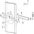
- a conductive nonferrous metal plate 101 which is long in an X direction, is assumed as illustrated in FIG. 1 .
- a rod-like permanent magnet 102 which is long in a Y direction, is disposed below the nonferrous metal plate 101 so as to be movable in the X direction.
- a permanent magnet of which both upper and lower end sides are magnetized to an N pole and an S pole, is used as the permanent magnet 102 in this embodiment. Accordingly, magnetic lines ML of force stand up vertically (in a height direction) from the permanent magnet 102. The magnetic lines ML of force penetrate the nonferrous metal plate 101 to the upper side from the lower side.
- a pair of electrodes 2a and 2a are provided on both side surfaces of the nonferrous metal plate 101 so as to face each other.
- a direct current I flows in the Y direction (a width direction), that is, horizontally between these pair of electrodes 2a and 2a. Accordingly, the horizontal current I and the magnetic lines ML of force, which are generated from the permanent magnet 102 in the height direction, cross each other. The magnetic lines ML of force actually move with the rotation of the permanent magnet as described below.
- an electromagnetic force (Lorentz force) f according to Fleming's left hand rule is generated at a portion, in which the current I flows, of the nonferrous metal plate 101. That is, a Lorentz force f, which drives the nonferrous metal plate 101 in the X direction and is generated according to Fleming's left hand rule, is applied to the nonferrous metal plate 101.
- the permanent magnet 102 is moved in the direction of an arrow AR (the X direction). Accordingly, the magnetic lines ML of force move while penetrating the nonferrous metal plate 101. Therefore, eddy currents 104 and 104 are generated in the nonferrous metal plate 101 on the front and rear sides of the magnetic lines ML of force in the X direction.
- the electromagnetic force f according to Fleming's rule is generated.
- the electromagnetic force fe caused by the eddy currents is generated.
- the inventor also intuits that the electromagnetic force fe caused by eddy currents is generated when the permanent magnet 102 is linearly moved in FIG. 1 .
- the magnetic field is a magnetic field generated from the rotating permanent magnet 102 (an actually assumed element is a permanent magnet rotating at a certain speed like a rotating-shifting magnetic field unit main body 8 of FIGS. 2A and 2B )
- those skilled in the art could not assure that the electromagnetic force f according to Fleming's rule can be really obtained as described above.
- the inventor repeated many experiments. Knowledge, which is obtained from these experiments and is unique to the inventor, was obtained. The inventor has made the invention on the basis of the knowledge. That is, the invention is said as an invention that cannot be made by those skilled in the art not performing the following experiments. The invention will be described below.
- the inventor continues making an effort day and night to develop a device that reliably drives and stirs molten metal M by a large force and is more excellent than a device in the related art. Since the inventor has uniquely thought of the device as described above everyday, the inventor has uniquely thought to simultaneously use the force f of the first technique and the force fe of the second technique. However, at first, similar to general those skilled in the art, the inventor has also vaguely thought that these two techniques are incompatible with each other. General engineers would give up here. However, since the inventor was eager to provide a new and excellent device, the inventor thought that two techniques are compatible with each other if devising something and could not give up hope of making the two techniques be compatible with each other.
- the inventor had an object that is unique to the inventor. For this reason, the inventor constantly repeated various experiments that would not be performed by general those skilled in the art. On the basis of the results of these experiments, the inventor obtained the unique knowledge that it is possible to obtain the resultant driving force (the combined driving force) F of the electromagnetic force f according to Fleming's rule and the electromagnetic force fe generated by eddy currents by making the first and second techniques be compatible with each other at the same time and to reliably drive and stir molten metal M by the resultant driving force F The inventor has made the invention on the basis of the unique knowledge.
- the invention has been made on the basis of the knowledge that is unique to the inventor and is based on the unique experiment results obtained by the inventor. Accordingly, the invention is said as an invention that cannot be made by other those skilled in the art not performing the above-mentioned experiments.
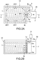
- FIGS. 2A and 2B illustrate a molten metal stirring device according to a first embodiment of the invention
- FIG. 2A is a plan view
- FIG. 2B is a vertical sectional view taken along line b-b of FIG. 2A
- the first embodiment is an embodiment in which a rotating-shifting magnetic field unit 20 is provided outside a side wall 1a of a furnace main body 1 of a main bath 10.
- the molten metal stirring device includes the main bath 10.
- Molten metal formed of metal having conductivity that is, molten metal formed of nonferrous metal (for example, Al, Cu, Zn, Si, an alloy including them as main components, a Mg alloy, or the like), or molten metal M formed of metal other than nonferrous metal is stored in a storage chamber 1A of the furnace main body 1 of the main bath 10.
- a pair of electrodes 2a and 2a are mounted on the side wall 1a of the furnace main body 1 of the main bath 10 so as to face each other in a vertical direction (a height direction).
- the pair of electrodes 2a and 2a are embedded in the side wall 1a, but do not necessarily need to be embedded and may be provided on the inner surface of the side wall 1a.
- these electrodes 2a and 2a are exposed from the side wall 1a and are in contact with the stored molten metal M. Accordingly, a current I can flow in a height direction between the electrodes 2a and 2a through the molten metal M.
- the electrodes 2a and 2a are connected to a power supply device 3 through wires 4a and 4a.
- a part of the wires 4a and 4a, that is, portions of the wires 4a and 4a close to the electrodes 2a and 2a are provided in the side wall 1a and are not in contact with the molten metal M.
- the reason why the direct current I is allowed to flow between the electrodes 2a and 2a is to obtain the Lorentz force (a second electromagnetic force) f according to Fleming's left hand rule as described above.
- the power supply device 3 is adapted to allow a direct current and an alternating current to flow in various modes by control signals that are sent from a control device (not illustrated).
- a direct current the polarities of the pair of electrodes 2a and 2a can be switched to each other.
- an alternating current a period, a waveform, and the like can be selected and adjusted.
- the waveform of the current I has, for example, a rectangular shape in the case of an alternating current
- the width of a positive pulse and the width of a negative pulse at one period can be arbitrarily set so that a duty ratio is changed.
- the power supply device 3 is adapted to be capable of arbitrarily setting a current value and a voltage value even when any one of a direct current and an alternating current is output.
- a current I flows in the vertical direction (a direct current Idc flows to the lower side from the upper side or to the upper side from the lower side or an alternating current lac flows) between the pair of electrodes 2a and 2a.
- the current I intersects the magnetic lines ML of force generated from the rotating-shifting magnetic field unit 20, so that the electromagnetic force (the second electromagnetic force) f according to Fleming's rule for driving the molten metal M in the direction of an arrow AR1 ( FIG. 2A ) is obtained.
- a direct current is allowed to flow between the pair of electrodes 2a and 2a when the outer periphery of the rotating-shifting magnetic field unit 20 is magnetized to one pole of an N pole and an S pole, and an alternating current synchronized with the periods of N poles and S poles (rotation periods) is allowed to flow between the pair of electrodes when N poles and S poles are alternately arranged on the outer periphery of the rotating-shifting magnetic field unit.
- the reason for this is to obtain a driving force f, which always drives molten metal M in the same direction, that is, in the direction of the arrow AR1, as an electromagnetic force according to Fleming's left hand rule.
- the reason why the current I flowing between the electrodes 2a and 2a is adapted to be capable of being set to any of a direct current and an alternating current by the power supply device 3 is to apply an electromagnetic force f, which is always applied in the same rotational direction, to the molten metal M even though any one of various rotating-shifting magnetic field unit main bodies 8 (see FIGS. 3A, 3B, 3C , 4A, 4B, and 4C ) to be described below is used.
- the rotating-shifting magnetic field unit 20 includes a chassis 7 that is made of a non-magnetic material, a rotating-shifting magnetic field unit main body 8 that is rotatably built in the chassis 7, and a drive unit (not illustrated) that drives the rotating-shifting magnetic field unit main body 8 clockwise (or counterclockwise).
- the rotating-shifting magnetic field unit main body 8 is rotatably installed so that input/output magnetic lines ML of force, which go out of the rotating-shifting magnetic field unit main body 8 or enter the rotating-shifting magnetic field unit main body 8, penetrate the molten metal M stored in the furnace main body 2 in a horizontal direction intersecting the vertical direction.
- the rotating-shifting magnetic field unit main body 8 functions as follows. That is, when a current I is allowed to flow in the vertical direction between the pair of electrodes 2a and 2a particularly in FIG. 2B , horizontal magnetic lines ML of force generated from the rotating-shifting magnetic field unit main body 8 intersect the current I. Accordingly, the Lorentz force (the second electromagnetic force) f, which drives the molten metal M as illustrated by the arrow AR1 of FIG. 2A , is generated.
- the rotating-shifting magnetic field unit main body 8 is rotated clockwise as illustrated in, for example, FIG. 2A when viewed from the upper side. Accordingly, the magnetic lines ML of force move while horizontally penetrating the molten metal M. Therefore, eddy currents are generated on the front and rear sides of the moving magnetic lines ML of force and the first electromagnetic force fe is generated by the eddy currents and the magnetic lines ML of force. Similar to the above-mentioned electromagnetic force f according to Fleming's left hand rule, the electromagnetic force fe generated by the eddy currents drives the molten metal M in the direction of the arrow AR1.
- the molten metal M is driven along the arrow AR1 by the resultant driving force F that is generated by the combination of the two electromagnetic forces, that is, the first and second electromagnetic forces fe and f. Therefore, the molten metal M stored in the furnace main body 1 is horizontally rotated as illustrated by an arrow AR11 of FIG. 2A .
- FIGS. 3A and 3B illustrate a first example of the rotating-shifting magnetic field unit main body
- FIG. 3C illustrates a modification of the first example
- FIGS. 4A and 4B illustrate a second example of the rotating-shifting magnetic field unit main body
- FIG. 4C illustrates a modification of the second example.
- the rotating-shifting magnetic field unit main body 8 includes a cylindrical case 8A that is made of a non-magnetic material and a rotating body 8B that is rotatably received in the case 8A.
- the rotating body 8B includes a long base 8B1 that is positioned at a rotation center portion thereof.
- the base 8B1 has a substantially square cross-section, and includes four side surfaces 8B2.
- a rod-like magnet 8B3, which is formed of a permanent magnet, is mounted on each of the side surfaces 8B2.
- the inner surface, which is mounted on the side surface 8B2, of each rod-like magnet 8B3 is magnetized to one pole (an S pole) and the outer surface thereof is magnetized to the other pole (an N pole).
- each rod-like magnet 8B3 may be magnetized to an S pole and the inner surface thereof is magnetized to an N pole so that S poles are arranged on the periphery of the rotating body 8B.
- FIG. 3C illustrates an example in which a plurality of rod-like magnets 8B3 mounted on the base 8B1 are alternately magnetized to an N pole and an S pole in a circumferential direction.
- a current I flowing in the same direction may be allowed to flow between the pair of electrodes 2a and 2a.
- N poles and S poles are alternately arranged along the outer periphery of the rotating body as illustrated in FIG. 3C
- an alternating current having a period corresponding to the arrangement of the magnetic poles needs to be allowed to flow between the pair of electrodes 2a and 2a as also briefly described above.
- the second electromagnetic force f according to Fleming's rule can be obtained as an electromagnetic force having the same direction (for example, the direction of the arrow AR1 of FIG. 2A ) even though the direction of the magnetic lines ML of force is alternately reversed.
- the control of the direction of the current I between the pair of electrodes 2a and 2a is performed by the control device as described above.
- the polygonal shape of the cross-section of the base 8B1 may be a polygonal shape of which the number of corners is arbitrary. Further, the number of the rod-like magnets 8B3 mounted on the base 8B1 may also be arbitrary.
- FIGS. 4A and 4B illustrate an example in which the number of the rod-like magnets 8B3 is set to 2 when the same poles are arranged on the outer periphery of the rotating body.
- FIG. 4C illustrates an example in which different magnetic poles are alternately arranged.
- the number of the rod-like magnets 8B3 mounted on the base 8B1 can be appropriately and arbitrarily determined as understood from the above description.
- the magnetic poles of the rod-like magnets 8B3 arranged in the circumferential direction can be arranged so that the same magnetic poles are arranged in the circumferential direction or different magnetic poles are alternately arranged in the circumferential direction.
- the cross-sectional shape of the base 8B1 may be an arbitrary polygonal shape according to the number of the provided rod-like magnets 8B3.
- a permanent magnet which is formed of a single permanent magnet and is magnetized so that the same magnetic poles or different magnetic poles are arranged therearound, may be used as the rotating body 8B.
- the pair of electrodes 2a and 2a do not necessarily need to be embedded in a furnace wall as illustrated in FIG. 2B and may be provided on the inner surface of a furnace wall 3a.
- the wires 4a and 4a may also be embedded in the furnace wall 3a or may be allowed to creep in the storage chamber 1A of the furnace main body 1 without being embedded so that the wires 4a and 4a are not in contact with the molten metal M.
- FIGS. 5A and 5B illustrates a molten metal stirring device according to a second embodiment of the invention
- FIG. 5A is a plan view
- FIG. 5B is a vertical sectional view taken along line b-b of FIG. 5A
- the second embodiment is different from the first embodiment ( FIGS. 2A and 2B ) in that the pair of electrodes 2a and 2a are also provided on the side wall 1a to horizontally face each other as particularly understood from FIG. 5A in response to the horizontal installation of the rotating-shifting magnetic field unit 20 so that a current I horizontally flows in the second embodiment.
- the rotating-shifting magnetic field unit main body 8 is adapted to be rotated clockwise in FIG. 5B .
- the rotating-shifting magnetic field unit 20 is adapted to be switched between a vertical position in the vertical direction as in the first embodiment and a horizontal position in which the rotating-shifting magnetic field unit lies down as in the second embodiment.
- the furnace main body 1 of the main bath 10 needs to be provided with the pair of electrodes 2a and 2a that are illustrated in FIG. 2B and face each other in the vertical direction and the pair of electrodes 2a and 2a that are illustrated in FIG. 5A and face each other in the horizontal direction, that is, a total of two pairs of electrodes 2a (four electrodes 2a).
- the rotating-shifting magnetic field unit 20 can be switched between the vertical position and the horizontal position so as to correspond to various conditions, such as an installation site, when used.
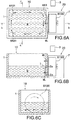
- FIG. 6A is a plan view of a third embodiment of the invention
- FIG. 6B is a vertical sectional view taken along line b-b of FIG. 6A
- FIG. 6C is a vertical sectional view taken along line c-c of FIG. 6A .
- the third embodiment is different from the first and second embodiments in terms of the structure of a rotating-shifting magnetic field unit main body. That is, a rotating-shifting magnetic field unit main body 81B0 illustrated in FIGS. 7A and 7B is used in the third embodiment. That is, a pair of rectangular permanent magnets 81B2 are mounted on the surface of a disc-shaped rotating substrate 81B1 at an arbitrary interval, for example, an interval of 180°. These permanent magnets 81B2 are mounted on the rotating substrate 81B1 so that the inner sides, which are mounted, of these permanent magnets 81B2 correspond to an S pole and the outer sides thereof correspond to an N pole. While the rotating-shifting magnetic field unit main body 81B0 illustrated in FIGS.
- molten metal M is driven in the direction of an arrow AR3 as illustrated in FIG. 6A by a resultant driving force F of an electromagnetic force f according to Fleming's left hand rule that is generated when a current I flows between the pair of electrodes 2a and 2a and an electromagnetic force fe that is generated by eddy currents generated when the rotating-shifting magnetic field unit main body 81B0 is rotated; and the molten metal M of the furnace main body 1 is driven and rotated as illustrated by arrows AR31.
- the plurality of permanent magnets 81B2 can also be mounted on the base 8B1 as illustrated in FIG. 7C so that different poles are arranged in a circumferential direction. In this case, an alternating current needs to be allowed to flow between the pair of electrodes 2a and 2a as described above.
- the rotating-shifting magnetic field unit 20 is merely provided later as long as the main bath 10 having been already provided includes a pair of electrodes 2a and 2a, the first to third embodiments having been described above are realized. Alternatively, as long as the pair of electrodes 2a and 2a and the rotating-shifting magnetic field unit 20 are provided later on the main bath 10 having been already provided, the embodiments of the invention can be realized.
- FIG. 8A is a horizontal sectional view of a fourth embodiment of the invention and FIG. 8B is a vertical sectional view taken along line b-b of FIG. 8A .
- the fourth embodiment is a so-called passage type stirring device that guides molten metal M of a main bath 30 to a so-called molten metal passage 41a, returns the molten metal M to a main bath 30 by applying the resultant driving force F to the molten metal M in the molten metal passage 41a, and stirs the molten metal M stored in the main bath 30.
- a molten metal stirring device includes a main bath 30 and a stirring unit 40.
- the main bath 30 includes a furnace main body 1 that stores molten metal M.
- the stirring unit 40 includes a passage member 41 that includes a molten metal passage 41a and a rotating-shifting magnetic field unit main body 8.
- a molten metal outlet 30a1 and a molten metal inlet 30a2 are formed in one side wall 30a of the main bath 30, and communicate with each other through the hollow passage member 41, which has a substantially U-shaped cross-section, of the stirring unit 40.
- the passage member 41 includes the molten metal passage 41a that is formed therein and has a substantially U-shaped cross-section. That is, one end of the molten metal passage 41a is connected to the molten metal outlet 30a1 so as to communicate with the molten metal outlet 30a1, and the other end of the molten metal passage 41a is connected to the molten metal inlet 30a2 so as to communicate with the molten metal inlet 30a2.
- the molten metal M of the main bath 30 flows out of the molten metal outlet 30a1 to the molten metal passage 41a, and then is driven in the molten metal passage 41a by the resultant driving force F as described below. After that, the molten metal M returns to the main bath 30 from the molten metal inlet 30b2.
- a storage space 40a is divided by the passage member 41 and the side wall 30a.
- the rotating-shifting magnetic field unit main body 8 is rotatably received in the storage space 40a.
- Various elements can be used as the rotating-shifting magnetic field unit main body 8, but the rotating-shifting magnetic field unit main bodies illustrated in, for example, FIGS. 3A, 3B, 3C , 4A, 4B, 4C , and the like can be used.
- FIGS. 3A and 3B when the rotating-shifting magnetic field unit main body illustrated in FIGS. 3A and 3B is used, magnetic lines ML of force horizontally extend and penetrate the molten metal M present in the molten metal passage 41a as particularly illustrated in FIG. 8B .
- a pair of electrodes 2a and 2a which face each other in the vertical direction, are provided on the inner wall of the passage member 41 so as to be exposed to the molten metal passage 41a.
- a current I flows between these electrodes 2a and 2a through the molten metal M in the vertical direction.
- These electrodes 2a and 2a are connected to a power supply device 3.
- a first electromagnetic force fe caused by eddy currents is generated by the rotation of the rotating-shifting magnetic field unit main body 8, and the molten metal M present in the molten metal passage 41a is also driven in the direction of the arrows AR4 by the electromagnetic force fe.
- a large resultant driving force F is generated by the combination of the second electromagnetic force f and the first electromagnetic force fe, acts on the molten metal M present in the molten metal passage 41a, allows the molten metal M to flow into the furnace main body 1 of the main bath 30 from the molten metal inlet 2b1, and allows the molten metal M of the main bath 30 to be sucked into the molten metal passage 41a from the molten metal inlet 2b1. Accordingly, as particularly illustrated in FIG. 8A , the molten metal M stored in the furnace main body 1 of the main bath 30 is reliably stirred and driven along arrows AR41.
- the rotating-shifting magnetic field unit main body 8 is installed inside the passage member 41 particularly in FIGS. 8A and 8B , but the rotating-shifting magnetic field unit main body 8 may be installed outside the passage member 41.
- the rotating-shifting magnetic field unit main bodies 81B0 illustrated in FIGS. 7A, 7B, and 7C can be used instead of the rotating-shifting magnetic field unit main body 8 so that a rotating shaft extends laterally.
- the molten metal present in the passage member 41 can also be driven by this structure.
- the rotating-shifting magnetic field unit main body 8 has been provided inside the so-called U shape of the U-shaped passage member 41, but may be provided outside the U shape of the passage member 41.
- a total of two rotating-shifting magnetic field unit main bodies 8 may be provided inside and outside the U shape so that the passage member 41 (the molten metal passage 41a) is interposed between the two rotating-shifting magnetic field unit main bodies 8.
- the magnetic lines ML of force generated from one rotating-shifting magnetic field unit main body 8 are shared in the above-mentioned embodiments so that two forces, that is, the electromagnetic force fe generated by eddy currents and the electromagnetic force f according to Fleming's rule are obtained.
- the pair of electrodes 2a and 2a are provided at other positions different from the positions of FIG.
- another magnetic field unit is provided in addition to the rotating-shifting magnetic field unit main body 8 and a pair of electrodes 2a and 2a can be provided at positions where an electromagnetic force f according to Fleming's rule is generated in relationship to the magnetic field unit. Even in this case, it is not possible to avoid an increase in the cost of the device and an increase in the size of the device as described above.
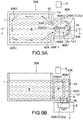
- FIG. 9A is a plan view of a fifth embodiment of the invention and FIG. 9B is a vertical sectional view taken along line b-b of FIG. 11A .
- the fifth embodiment is different from the fourth embodiment of FIGS. 8A and 8B in terms of the structure of a stirring unit 40A. That is, this embodiment is an embodiment in which a stirring chamber 40A1 communicating with a main bath 30A is made and molten metal M is driven by a resultant driving force F.
- a molten metal stirring device includes the main bath 30A and the stirring unit 40A.
- the main bath 30A includes a furnace main body 1 that stores molten metal M.
- Aside wall 1a1, which has a substantially U-shaped cross-section, of the stirring unit 40A is formed so as to be connected to one side wall 1a of the furnace main body 1.
- the stirring chamber 40A1 of the stirring unit 40A which communicates with the inside of the furnace main body 1 of the main bath 30A, is formed by the side wall 1a1.
- a partition plate 40A0 stands upright in the direction of the flow of the molten metal in the stirring chamber 40A1.
- the opening 50 is partitioned into two openings 50A and 50B by the partition plate 40A0, and the stirring chamber 40A1 is partitioned into two upper and lower chambers illustrated in FIG. 9A , that is, a first chamber 40A11 and a second chamber 40A12.
- the partition plate 40A0 is provided so as to be rotatable about a shaft portion 40A10.
- the width of the opening 50A of the first chamber 40A11 and the width of the opening 50B of the second chamber 40A12 are adjusted by the rotation of the partition plate 40A0, and the flow of the molten metal becomes optimal as described below.
- a gap G which allows the flow of the molten metal M, is formed between the shaft portion 40A10 and the inside of the side wall 1a1. Accordingly, the molten metal M can circulate through the opening 50A, the first chamber 40A11, the gap G, the second chamber 40A12, the opening 50B, and the furnace main body 1 from the inside of the furnace main body 1 of the main bath 30A as described below.
- the partition plate 40A1 includes a partition plate main body 40A10 and the shaft portion 40A0.
- the shaft portion 40A10 (2a) is made of a conductive material, and functions as one of the pair of electrodes 2a and 2a.
- a plurality of the other electrodes 2a are provided on the inside of the side wall 1a1. Accordingly, a current I horizontally flows between one shaft portion 40A10 (2a) and the plurality of electrodes 2a through the molten metal M. That is, a plurality of paths for the current I are formed horizontally.
- One electrode 40A10 (2a) and the plurality of the other electrodes 2a are connected to terminals of both poles of the power supply device 3.
- a rotating-shifting magnetic field unit 20 is provided below the bottom wall of the stirring chamber 40A1 in the stirring unit 40A.
- a rotating-shifting magnetic field unit main body 8 is provided in the rotating-shifting magnetic field unit 20 so as to be rotatable about an axis extending in a vertical direction.
- the rotating-shifting magnetic field unit main body which is illustrated in FIGS. 7A and 7B or FIG. 7C , or the like can be used as the rotating-shifting magnetic field unit main body 8.
- magnetic lines ML of force stand up as illustrated in FIG. 9B .
- the second electromagnetic force f is generated by the intersection between the magnetic lines ML of force and the current I that flows between the shaft portion 40A10 (2a) and the electrodes 2a. Further, the first electromagnetic force fe caused by eddy currents is also generated with the rotation of the rotating-shifting magnetic field unit main body 8. Accordingly, the molten metal M is driven in the direction of arrows AR5 ( FIG. 9A ) by the resultant driving force F of these two electromagnetic forces f and fe. Therefore, the molten metal M is rotated and stirred in the furnace main body 1 as illustrated by arrows AR51.
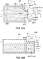
- FIGS. 10A and 10B illustrate a sixth embodiment of the invention, and illustrate a case in which the rotating-shifting magnetic field unit 20 of FIGS. 9A and 9B is installed above the stirring chamber 40A1. Meanwhile, it is natural that the rotating-shifting magnetic field unit main body 8 of FIG. 9B is installed so as to be inverted.
- FIG. 11A is a vertical sectional view of a seventh embodiment
- FIG. 11B is a sectional view taken along line b-b.
- the seventh embodiment includes two melting furnaces, that is, main baths 100 and 101.
- a molten metal furnace system which includes a molten metal transfer device for transferring molten metal M to a furnace main body 101A of the main bath 101 from a furnace main body 100A of the main bath 100, is illustrated.
- an opening 100b is formed in a bottom wall 100a of one main bath 100, and an opening 101b is formed in a bottom wall 101a of the other main bath 101.
- These openings 100b and 101b communicate with each other through a hollow passage member 103 that is bent substantially in a U shape.
- the cross-sectional shape of the passage member 103 is illustrated in FIG. 11B .
- the cross-sectional shape of a communication passage 103a formed in the passage member 103 is a rectangular shape.
- a pair of electrodes 2a and 2a are provided on the inner surfaces, which face each other in a width direction with the communication passage 103a of the passage member 103 interposed therebetween, of a pair of side walls 103b and 103b. As illustrated in FIG.
- the pair of electrodes 2a and 2a are provided above a curved portion 103c of the passage member 103 that is bent in a vertical direction.
- a rotating-shifting magnetic field unit main body 8 is horizontally provided on the inside (at an upper portion) of the curved portion 103c.
- the rotating-shifting magnetic field unit main body 8 is illustrated in FIGS. 3A, 3B, 3C , 4A, 4B, and 4C .
- the electrodes 2a and 2a are connected to a power supply device 3.
- molten metal M present in the passage member 103 can be transferred to the other main bath 101 from one main bath 100 by a resultant driving force F of a second electromagnetic force f according to Fleming's rule and a first electromagnetic force fe generated by eddy currents.
- the inventor has made an experiment to drive molten aluminum according to each of the above-mentioned embodiments, and has confirmed that a driving force (transfer force) can be made larger than each of the electromagnetic force fe generated by eddy currents and the electromagnetic force f according to Fleming's rule.
- a driving force transfer force
- the inventor has made an experiment formed of the combination of a case in which the amount of molten metal transferred by only the Lorentz force f is about 1000 Tons/h and a case in which the amount of molten metal transferred by only the electromagnetic force fe, which is generated by eddy currents, is about 900 Tons/h; and has numerically confirmed that the amount of transferred molten metal can be set in the range of about 1800 to 2000 Tons/h.
Landscapes
- Engineering & Computer Science (AREA)
- Mechanical Engineering (AREA)
- General Engineering & Computer Science (AREA)
- Waste-Gas Treatment And Other Accessory Devices For Furnaces (AREA)
- Vertical, Hearth, Or Arc Furnaces (AREA)
- Continuous Casting (AREA)
- Furnace Charging Or Discharging (AREA)
Claims (12)
- Dispositif d'agitation de métal en fusion comprenant :un corps principal de four (1) qui comprend une chambre de stockage (1A) stockant du métal en fusion formé avec un métal conducteur ; etun corps principal d'unité de champ magnétique de rotation - déplacement (8) qui peut tourner pour entraîner et agiter le métal en fusion stocké dans le corps principal de four (1),dans lequel le corps principal d'unité de champ magnétique de rotation - déplacement (1) comprend un aimant permanent (8B3), de sorte que des lignes de force magnétique d'entrée / sortie, qui sortent de l'aimant permanent (8B3) ou entrent dans l'aimant permanent (8B3), se déplacent avec la rotation du corps principal d'unité de champ magnétique de rotation - déplacement (1) tout en pénétrant dans le métal en fusion (M), de sorte qu'une première force électromagnétique (fe) pour entraîner le métal en fusion est générée par les courants de Foucault qui sont générés par le mouvement des lignes de force magnétique d'entrée / sortie,le corps principal de four (1) comprend au moins une paire d'électrodes (2a) qui permet au courant de s'écouler à travers le métal en fusion (M),la paire d'électrodes (2a) est prévue dans la chambre de stockage (1) dans des positions dans lesquelles le courant s'écoulant entre la paire d'électrodes (2a) et les lignes de force magnétique d'entrée / sortie se coupent et génèrent une seconde force électromagnétique (f) pour entraîner le métal en fusion (M) dans la même direction que la première force électromagnétique (fe), etle métal en fusion (M) stocké dans la chambre de stockage (1A) est entraîné et agité par une force d'entraînement résultante (F) des première et seconde forces électromagnétiques (fe, f).
- Dispositif d'agitation de métal en fusion selon la revendication 1,
dans lequel la paire d'électrodes (2a) est prévue à un intervalle prédéterminé dans une direction verticale parallèle à une direction de hauteur, et
le corps principal d'unité du champ magnétique de rotation - déplacement (8) est prévu afin de pouvoir tourner autour d'un axe vertical. - Dispositif d'agitation de métal en fusion selon la revendication 1,
dans lequel la paire d'électrodes (2a) est prévue à un intervalle prédéterminé dans une direction horizontale coupant une direction de hauteur, et
le corps principal d'unité de champ magnétique de rotation - déplacement (8) est prévu afin de pouvoir tourner autour d'un axe horizontal. - Dispositif d'agitation de métal en fusion selon la revendication 1,
dans lequel le corps principal d'unité de champ magnétique de rotation - déplacement (8) comprend un ou une pluralité d'aimants permanents (8B3), et
les mêmes pôles magnétiques sont agencés autour d'un axe vertical s'étendant dans une direction de hauteur ou un axe horizontal coupant la direction de hauteur. - Dispositif d'agitation de métal en fusion selon la revendication 1,
dans lequel le corps principal d'unité de champ magnétique de rotation - déplacement (8) comprend un ou une pluralité d'aimants permanents (8B3), et
différents pôles magnétiques sont agencés de manière alternée autour d'un axe vertical s'étendant dans une direction de hauteur ou un axe horizontal coupant la direction de hauteur. - Dispositif d'agitation de métal en fusion selon la revendication 5, comprenant en outre :une pluralité d'aimants permanents (8B3),dans lequel la pluralité d'aimants permanents (8B3) sont agencés autour de l'axe vertical ou de l'axe horizontal.
- Dispositif d'agitation de métal en fusion selon la revendication 1, comprenant en outre :deux paires d'électrodes comprenant une première paire d'électrodes (2a) et une seconde paire d'électrodes (2a),dans lequel la première paire d'électrodes (2a) est prévue à un intervalle prédéterminé dans une direction verticale parallèle à une direction de hauteur,la seconde paire d'électrodes (2a) est prévue à un intervalle prédéterminé dans une direction horizontale coupant la direction de hauteur, etle corps principal d'unité de champ magnétique de rotation - déplacement (8) est adapté pour être commuté entre une première position d'installation dans laquelle le corps principal d'unité de champ magnétique de rotation - déplacement (8) est prévu afin de pouvoir tourner autour d'un axe vertical et une seconde position d'installation dans laquelle le corps principal d'unité de champ magnétique de rotation - déplacement (8) est prévu afin de pouvoir tourner autour d'un axe horizontal.
- Dispositif d'agitation de métal en fusion selon la revendication 1,
dans lequel la paire d'électrodes (2a) est prévue à un intervalle prédéterminé dans une direction verticale parallèle à une direction de hauteur, et
le corps principal d'unité de champ magnétique de rotation - déplacement (8) est prévu afin de pouvoir tourner autour d'un axe horizontal coupant la direction de hauteur. - Dispositif d'agitation de métal en fusion selon la revendication 8,
dans lequel le corps principal d'unité de champ magnétique de rotation - déplacement (8) comprend un ou une pluralité d'aimants permanents (8B3), et
les mêmes pôles magnétiques sont agencés autour de l'axe horizontal. - Dispositif d'agitation de métal en fusion selon la revendication 8,
dans lequel le corps principal d'unité de champ magnétique de rotation - déplacement (8) comprend un ou une pluralité d'aimants permanents (8B3), et
différents pôles magnétiques sont agencés de manière alternée autour de l'axe horizontal. - Dispositif d'agitation de métal en fusion selon la revendication 4,
dans lequel un dispositif d'alimentation en énergie (3), qui permet à un courant continu de s'écouler, est raccordé entre la paire d'électrodes (2a). - Dispositif d'agitation de métal en fusion selon la revendication 5,
dans lequel le dispositif d'alimentation en énergie (3), qui permet à un courant alternatif de s'écouler, est raccordé entre la paire d'électrodes (2a), et
la période du courant alternatif est contrôlée en relation avec les périodes de rotation des différents pôles magnétiques du corps principal d'unité de champ magnétique de rotation - déplacement (8) de sorte que la première force électromagnétique (fe) entraîne le métal en fusion dans la même direction.
Applications Claiming Priority (2)
| Application Number | Priority Date | Filing Date | Title |
|---|---|---|---|
| JP2014066995A JP6033807B2 (ja) | 2014-03-27 | 2014-03-27 | 金属溶湯攪拌装置及び金属溶湯移送装置 |
| PCT/JP2015/059392 WO2015147170A1 (fr) | 2014-03-27 | 2015-03-26 | Dispositif d'agitation de métal en fusion et dispositif de transfert de métal en fusion |
Publications (3)
| Publication Number | Publication Date |
|---|---|
| EP3124904A1 EP3124904A1 (fr) | 2017-02-01 |
| EP3124904A4 EP3124904A4 (fr) | 2017-11-22 |
| EP3124904B1 true EP3124904B1 (fr) | 2020-09-23 |
Family
ID=54195676
Family Applications (1)
| Application Number | Title | Priority Date | Filing Date |
|---|---|---|---|
| EP15767968.9A Not-in-force EP3124904B1 (fr) | 2014-03-27 | 2015-03-26 | Dispositif d'agitation de métal en fusion |
Country Status (9)
| Country | Link |
|---|---|
| US (1) | US10281216B2 (fr) |
| EP (1) | EP3124904B1 (fr) |
| JP (1) | JP6033807B2 (fr) |
| KR (1) | KR101869834B1 (fr) |
| CN (1) | CN106170673B (fr) |
| AU (1) | AU2015234864B2 (fr) |
| CA (1) | CA2943648C (fr) |
| NZ (1) | NZ724542A (fr) |
| WO (1) | WO2015147170A1 (fr) |
Families Citing this family (6)
| Publication number | Priority date | Publication date | Assignee | Title |
|---|---|---|---|---|
| AU2019237468B2 (en) | 2018-03-20 | 2022-01-27 | Kenzo Takahashi | Molten metal pump and method of adjusting pumping capacity of molten metal pump |
| JP7515173B2 (ja) * | 2020-12-21 | 2024-07-12 | 株式会社ヂーマグ | 金属溶湯ポンプ |
| WO2023033637A1 (fr) * | 2021-09-03 | 2023-03-09 | Latvijas Universitāte | Dispositif d'induction sans contact d'écoulement dans des liquides électriquement conducteurs |
| JP2024034910A (ja) * | 2022-09-01 | 2024-03-13 | 株式会社ヂーマグ | 磁場装置および溶湯駆動方法 |
| CN116164536A (zh) * | 2023-03-02 | 2023-05-26 | 东北大学 | 一种交替方向脉冲序列的永磁搅拌金属熔体流动的方法 |
| WO2026064384A1 (fr) * | 2024-09-17 | 2026-03-26 | Pyrotek, Inc. | Amorçage et dégazage de filtre à aimant permanent |
Family Cites Families (16)
| Publication number | Priority date | Publication date | Assignee | Title |
|---|---|---|---|---|
| JPS5851779B2 (ja) * | 1980-04-01 | 1983-11-18 | 株式会社神戸製鋼所 | 連続鋳造設備における溶鋼撹拌方法 |
| CN1008984B (zh) * | 1987-06-01 | 1990-08-01 | 冶金工业部武汉钢铁设计研究院 | 连续铸钢电磁搅拌装置 |
| JP3056659B2 (ja) * | 1994-12-09 | 2000-06-26 | 新日本製鐵株式会社 | 溶融金属の連続鋳造方法 |
| JP4245673B2 (ja) | 1996-11-14 | 2009-03-25 | 高橋 謙三 | 攪拌装置付きアルミ溶解炉、溶融アルミ攪拌装置及び溶湯アルミ攪拌方法 |
| JP4376771B2 (ja) * | 2004-12-22 | 2009-12-02 | 高橋 謙三 | 攪拌装置 |
| KR101213559B1 (ko) * | 2004-12-22 | 2012-12-18 | 겐조 다카하시 | 교반장치 및 방법과, 그 교반장치를 이용한 교반장치 부착용해로 |
| JP2006349293A (ja) * | 2005-06-17 | 2006-12-28 | Kenzo Takahashi | 攪拌装置付溶解炉及び溶解炉用攪拌装置 |
| US7651656B2 (en) * | 2006-07-20 | 2010-01-26 | Kenzo Takahashi | Melting furnace with agitator and agitator for melting furnace |
| DE102007037340B4 (de) * | 2007-08-03 | 2010-02-25 | Forschungszentrum Dresden - Rossendorf E.V. | Verfahren und Einrichtung zum elektromagnetischen Rühren von elektrisch leitenden Flüssigkeiten |
| JP5646138B2 (ja) * | 2008-06-27 | 2014-12-24 | 高橋 謙三 | 攪拌装置付溶解炉 |
| JP4995234B2 (ja) | 2008-12-26 | 2012-08-08 | 株式会社ヂーマグ | 非鉄金属溶湯ポンプ及びそれを用いた非鉄金属溶解炉 |
| JP5550885B2 (ja) * | 2009-11-12 | 2014-07-16 | 高橋 謙三 | 溶解炉システム |
| JP5474879B2 (ja) | 2011-07-04 | 2014-04-16 | 高橋 謙三 | 攪拌装置付金属溶解炉 |
| JP5766572B2 (ja) * | 2011-09-30 | 2015-08-19 | 高橋 謙三 | 金属溶解炉用渦室体及びそれを用いた金属溶解炉 |
| JP5819270B2 (ja) | 2012-08-08 | 2015-11-18 | 高橋 謙三 | 永久磁石式筒型溶湯攪拌装置及び永久磁石式汲み出しポンプ付溶解炉 |
| JP5813693B2 (ja) * | 2013-04-23 | 2015-11-17 | 高橋 謙三 | 溶湯金属循環駆動装置及びそれを有するメインバス |
-
2014
- 2014-03-27 JP JP2014066995A patent/JP6033807B2/ja active Active
-
2015
- 2015-03-26 WO PCT/JP2015/059392 patent/WO2015147170A1/fr not_active Ceased
- 2015-03-26 KR KR1020167028430A patent/KR101869834B1/ko not_active Expired - Fee Related
- 2015-03-26 NZ NZ724542A patent/NZ724542A/en not_active IP Right Cessation
- 2015-03-26 EP EP15767968.9A patent/EP3124904B1/fr not_active Not-in-force
- 2015-03-26 CN CN201580016511.5A patent/CN106170673B/zh not_active Expired - Fee Related
- 2015-03-26 AU AU2015234864A patent/AU2015234864B2/en not_active Ceased
- 2015-03-26 CA CA2943648A patent/CA2943648C/fr not_active Expired - Fee Related
- 2015-03-26 US US15/129,616 patent/US10281216B2/en not_active Expired - Fee Related
Non-Patent Citations (1)
| Title |
|---|
| None * |
Also Published As
| Publication number | Publication date |
|---|---|
| KR101869834B1 (ko) | 2018-06-21 |
| AU2015234864A1 (en) | 2016-10-20 |
| AU2015234864B2 (en) | 2017-11-02 |
| CN106170673B (zh) | 2018-01-02 |
| JP6033807B2 (ja) | 2016-11-30 |
| US20170176107A1 (en) | 2017-06-22 |
| EP3124904A4 (fr) | 2017-11-22 |
| CN106170673A (zh) | 2016-11-30 |
| WO2015147170A1 (fr) | 2015-10-01 |
| EP3124904A1 (fr) | 2017-02-01 |
| NZ724542A (en) | 2018-04-27 |
| US10281216B2 (en) | 2019-05-07 |
| CA2943648C (fr) | 2018-01-02 |
| JP2015190661A (ja) | 2015-11-02 |
| KR20160134745A (ko) | 2016-11-23 |
| CA2943648A1 (fr) | 2015-10-01 |
Similar Documents
| Publication | Publication Date | Title |
|---|---|---|
| EP3124904B1 (fr) | Dispositif d'agitation de métal en fusion | |
| EP2708839B1 (fr) | Dispositif d'agitation de métal fondu cylindrique de type aimant permanent, et four de fusion | |
| Li et al. | Magnetically‐and electrically‐controllable functional liquid metal droplets | |
| US7262531B2 (en) | Magnetic suspension bearing | |
| US20040234379A1 (en) | Direct current magnetohydrodynamic pump configurations | |
| US20140219823A1 (en) | Micropump | |
| JP2014035131A5 (fr) | ||
| JP5372328B2 (ja) | 溶解炉用撹拌装置及び攪拌装置付溶解炉 | |
| JP2006349293A (ja) | 攪拌装置付溶解炉及び溶解炉用攪拌装置 | |
| Tieriekhov et al. | Wireless magnetoelectrochemical induction of rotational motion | |
| Lozon et al. | Chemically‐Driven Autonomous Janus Electromagnets as Magnetotactic Swimmers | |
| Yachikov et al. | Behavior of conducting liquid within an arc furnace in a vertical magnetic field | |
| JP2011257129A (ja) | 攪拌装置付溶解炉及び溶解炉用攪拌装置 | |
| Sharma et al. | Microflow Switching using Artificial Cilia for On‐Demand Particle Manipulation | |
| KR100978828B1 (ko) | 분할 코일체를 갖는 회전판과 분할 자석체를 갖는 고정판에의한 전동장치 | |
| RU167107U1 (ru) | Электрическая машина радиального действия | |
| Murdoch et al. | Magnetic field-enabled co-electrodeposition of luminescent yttria particles | |
| CN103973075A (zh) | 盐液流磁力发电装置 | |
| Fuchs et al. | A liquid metal droplet rotary paddle motor | |
| PT91565B (pt) | Dispositivo para bombear metal fundido de um reservatorio | |
| Clark et al. | Control of fluid flow using redox magnetohydrodynamics for chip-based microfluidics and analytical applications | |
| Hatlo et al. | The Electrostatic Force between Dielectric Bodies | |
| PL169292B1 (pl) | Urządzenie do pokazu ruchu elektrolitu w polu magnetycznym | |
| CN101047057A (zh) | 永磁磁场的消磁与变极控制技术 |
Legal Events
| Date | Code | Title | Description |
|---|---|---|---|
| STAA | Information on the status of an ep patent application or granted ep patent |
Free format text: STATUS: THE INTERNATIONAL PUBLICATION HAS BEEN MADE |
|
| PUAI | Public reference made under article 153(3) epc to a published international application that has entered the european phase |
Free format text: ORIGINAL CODE: 0009012 |
|
| STAA | Information on the status of an ep patent application or granted ep patent |
Free format text: STATUS: REQUEST FOR EXAMINATION WAS MADE |
|
| 17P | Request for examination filed |
Effective date: 20161025 |
|
| AK | Designated contracting states |
Kind code of ref document: A1 Designated state(s): AL AT BE BG CH CY CZ DE DK EE ES FI FR GB GR HR HU IE IS IT LI LT LU LV MC MK MT NL NO PL PT RO RS SE SI SK SM TR |
|
| AX | Request for extension of the european patent |
Extension state: BA ME |
|
| DAV | Request for validation of the european patent (deleted) | ||
| DAX | Request for extension of the european patent (deleted) | ||
| A4 | Supplementary search report drawn up and despatched |
Effective date: 20171023 |
|
| RIC1 | Information provided on ipc code assigned before grant |
Ipc: F27D 3/14 20060101ALI20171017BHEP Ipc: F27D 27/00 20100101AFI20171017BHEP Ipc: B22D 1/00 20060101ALI20171017BHEP Ipc: B22D 35/00 20060101ALI20171017BHEP Ipc: B22D 27/02 20060101ALI20171017BHEP |
|
| GRAP | Despatch of communication of intention to grant a patent |
Free format text: ORIGINAL CODE: EPIDOSNIGR1 |
|
| STAA | Information on the status of an ep patent application or granted ep patent |
Free format text: STATUS: GRANT OF PATENT IS INTENDED |
|
| INTG | Intention to grant announced |
Effective date: 20200407 |
|
| GRAS | Grant fee paid |
Free format text: ORIGINAL CODE: EPIDOSNIGR3 |
|
| GRAA | (expected) grant |
Free format text: ORIGINAL CODE: 0009210 |
|
| STAA | Information on the status of an ep patent application or granted ep patent |
Free format text: STATUS: THE PATENT HAS BEEN GRANTED |
|
| AK | Designated contracting states |
Kind code of ref document: B1 Designated state(s): AL AT BE BG CH CY CZ DE DK EE ES FI FR GB GR HR HU IE IS IT LI LT LU LV MC MK MT NL NO PL PT RO RS SE SI SK SM TR |
|
| REG | Reference to a national code |
Ref country code: GB Ref legal event code: FG4D |
|
| REG | Reference to a national code |
Ref country code: CH Ref legal event code: EP |
|
| REG | Reference to a national code |
Ref country code: IE Ref legal event code: FG4D |
|
| REG | Reference to a national code |
Ref country code: DE Ref legal event code: R096 Ref document number: 602015059541 Country of ref document: DE Ref country code: AT Ref legal event code: REF Ref document number: 1316814 Country of ref document: AT Kind code of ref document: T Effective date: 20201015 |
|
| REG | Reference to a national code |
Ref country code: NO Ref legal event code: T2 Effective date: 20200923 |
|
| REG | Reference to a national code |
Ref country code: NL Ref legal event code: FP |
|
| PG25 | Lapsed in a contracting state [announced via postgrant information from national office to epo] |
Ref country code: HR Free format text: LAPSE BECAUSE OF FAILURE TO SUBMIT A TRANSLATION OF THE DESCRIPTION OR TO PAY THE FEE WITHIN THE PRESCRIBED TIME-LIMIT Effective date: 20200923 Ref country code: GR Free format text: LAPSE BECAUSE OF FAILURE TO SUBMIT A TRANSLATION OF THE DESCRIPTION OR TO PAY THE FEE WITHIN THE PRESCRIBED TIME-LIMIT Effective date: 20201224 Ref country code: FI Free format text: LAPSE BECAUSE OF FAILURE TO SUBMIT A TRANSLATION OF THE DESCRIPTION OR TO PAY THE FEE WITHIN THE PRESCRIBED TIME-LIMIT Effective date: 20200923 Ref country code: SE Free format text: LAPSE BECAUSE OF FAILURE TO SUBMIT A TRANSLATION OF THE DESCRIPTION OR TO PAY THE FEE WITHIN THE PRESCRIBED TIME-LIMIT Effective date: 20200923 Ref country code: BG Free format text: LAPSE BECAUSE OF FAILURE TO SUBMIT A TRANSLATION OF THE DESCRIPTION OR TO PAY THE FEE WITHIN THE PRESCRIBED TIME-LIMIT Effective date: 20201223 |
|
| PG25 | Lapsed in a contracting state [announced via postgrant information from national office to epo] |
Ref country code: LV Free format text: LAPSE BECAUSE OF FAILURE TO SUBMIT A TRANSLATION OF THE DESCRIPTION OR TO PAY THE FEE WITHIN THE PRESCRIBED TIME-LIMIT Effective date: 20200923 Ref country code: RS Free format text: LAPSE BECAUSE OF FAILURE TO SUBMIT A TRANSLATION OF THE DESCRIPTION OR TO PAY THE FEE WITHIN THE PRESCRIBED TIME-LIMIT Effective date: 20200923 |
|
| REG | Reference to a national code |
Ref country code: LT Ref legal event code: MG4D |
|
| PG25 | Lapsed in a contracting state [announced via postgrant information from national office to epo] |
Ref country code: CZ Free format text: LAPSE BECAUSE OF FAILURE TO SUBMIT A TRANSLATION OF THE DESCRIPTION OR TO PAY THE FEE WITHIN THE PRESCRIBED TIME-LIMIT Effective date: 20200923 Ref country code: LT Free format text: LAPSE BECAUSE OF FAILURE TO SUBMIT A TRANSLATION OF THE DESCRIPTION OR TO PAY THE FEE WITHIN THE PRESCRIBED TIME-LIMIT Effective date: 20200923 Ref country code: PT Free format text: LAPSE BECAUSE OF FAILURE TO SUBMIT A TRANSLATION OF THE DESCRIPTION OR TO PAY THE FEE WITHIN THE PRESCRIBED TIME-LIMIT Effective date: 20210125 Ref country code: RO Free format text: LAPSE BECAUSE OF FAILURE TO SUBMIT A TRANSLATION OF THE DESCRIPTION OR TO PAY THE FEE WITHIN THE PRESCRIBED TIME-LIMIT Effective date: 20200923 Ref country code: SM Free format text: LAPSE BECAUSE OF FAILURE TO SUBMIT A TRANSLATION OF THE DESCRIPTION OR TO PAY THE FEE WITHIN THE PRESCRIBED TIME-LIMIT Effective date: 20200923 Ref country code: EE Free format text: LAPSE BECAUSE OF FAILURE TO SUBMIT A TRANSLATION OF THE DESCRIPTION OR TO PAY THE FEE WITHIN THE PRESCRIBED TIME-LIMIT Effective date: 20200923 |
|
| PGFP | Annual fee paid to national office [announced via postgrant information from national office to epo] |
Ref country code: NO Payment date: 20210215 Year of fee payment: 7 Ref country code: NL Payment date: 20210223 Year of fee payment: 7 Ref country code: FR Payment date: 20210309 Year of fee payment: 7 Ref country code: IT Payment date: 20210316 Year of fee payment: 7 |
|
| PG25 | Lapsed in a contracting state [announced via postgrant information from national office to epo] |
Ref country code: ES Free format text: LAPSE BECAUSE OF FAILURE TO SUBMIT A TRANSLATION OF THE DESCRIPTION OR TO PAY THE FEE WITHIN THE PRESCRIBED TIME-LIMIT Effective date: 20200923 Ref country code: AL Free format text: LAPSE BECAUSE OF FAILURE TO SUBMIT A TRANSLATION OF THE DESCRIPTION OR TO PAY THE FEE WITHIN THE PRESCRIBED TIME-LIMIT Effective date: 20200923 Ref country code: IS Free format text: LAPSE BECAUSE OF FAILURE TO SUBMIT A TRANSLATION OF THE DESCRIPTION OR TO PAY THE FEE WITHIN THE PRESCRIBED TIME-LIMIT Effective date: 20210123 Ref country code: PL Free format text: LAPSE BECAUSE OF FAILURE TO SUBMIT A TRANSLATION OF THE DESCRIPTION OR TO PAY THE FEE WITHIN THE PRESCRIBED TIME-LIMIT Effective date: 20200923 |
|
| PGFP | Annual fee paid to national office [announced via postgrant information from national office to epo] |
Ref country code: AT Payment date: 20210218 Year of fee payment: 7 Ref country code: GB Payment date: 20210212 Year of fee payment: 7 Ref country code: DE Payment date: 20210310 Year of fee payment: 7 |
|
| REG | Reference to a national code |
Ref country code: DE Ref legal event code: R097 Ref document number: 602015059541 Country of ref document: DE |
|
| PG25 | Lapsed in a contracting state [announced via postgrant information from national office to epo] |
Ref country code: SK Free format text: LAPSE BECAUSE OF FAILURE TO SUBMIT A TRANSLATION OF THE DESCRIPTION OR TO PAY THE FEE WITHIN THE PRESCRIBED TIME-LIMIT Effective date: 20200923 |
|
| PLBE | No opposition filed within time limit |
Free format text: ORIGINAL CODE: 0009261 |
|
| STAA | Information on the status of an ep patent application or granted ep patent |
Free format text: STATUS: NO OPPOSITION FILED WITHIN TIME LIMIT |
|
| PG25 | Lapsed in a contracting state [announced via postgrant information from national office to epo] |
Ref country code: DK Free format text: LAPSE BECAUSE OF FAILURE TO SUBMIT A TRANSLATION OF THE DESCRIPTION OR TO PAY THE FEE WITHIN THE PRESCRIBED TIME-LIMIT Effective date: 20200923 Ref country code: SI Free format text: LAPSE BECAUSE OF FAILURE TO SUBMIT A TRANSLATION OF THE DESCRIPTION OR TO PAY THE FEE WITHIN THE PRESCRIBED TIME-LIMIT Effective date: 20200923 |
|
| 26N | No opposition filed |
Effective date: 20210624 |
|
| PG25 | Lapsed in a contracting state [announced via postgrant information from national office to epo] |
Ref country code: MC Free format text: LAPSE BECAUSE OF FAILURE TO SUBMIT A TRANSLATION OF THE DESCRIPTION OR TO PAY THE FEE WITHIN THE PRESCRIBED TIME-LIMIT Effective date: 20200923 |
|
| REG | Reference to a national code |
Ref country code: CH Ref legal event code: PL |
|
| REG | Reference to a national code |
Ref country code: BE Ref legal event code: MM Effective date: 20210331 |
|
| PG25 | Lapsed in a contracting state [announced via postgrant information from national office to epo] |
Ref country code: CH Free format text: LAPSE BECAUSE OF NON-PAYMENT OF DUE FEES Effective date: 20210331 Ref country code: LU Free format text: LAPSE BECAUSE OF NON-PAYMENT OF DUE FEES Effective date: 20210326 Ref country code: LI Free format text: LAPSE BECAUSE OF NON-PAYMENT OF DUE FEES Effective date: 20210331 Ref country code: IE Free format text: LAPSE BECAUSE OF NON-PAYMENT OF DUE FEES Effective date: 20210326 |
|
| PG25 | Lapsed in a contracting state [announced via postgrant information from national office to epo] |
Ref country code: BE Free format text: LAPSE BECAUSE OF NON-PAYMENT OF DUE FEES Effective date: 20210331 |
|
| REG | Reference to a national code |
Ref country code: DE Ref legal event code: R119 Ref document number: 602015059541 Country of ref document: DE |
|
| REG | Reference to a national code |
Ref country code: NO Ref legal event code: MMEP |
|
| REG | Reference to a national code |
Ref country code: NL Ref legal event code: MM Effective date: 20220401 |
|
| REG | Reference to a national code |
Ref country code: AT Ref legal event code: MM01 Ref document number: 1316814 Country of ref document: AT Kind code of ref document: T Effective date: 20220326 |
|
| GBPC | Gb: european patent ceased through non-payment of renewal fee |
Effective date: 20220326 |
|
| PG25 | Lapsed in a contracting state [announced via postgrant information from national office to epo] |
Ref country code: NO Free format text: LAPSE BECAUSE OF NON-PAYMENT OF DUE FEES Effective date: 20220331 Ref country code: NL Free format text: LAPSE BECAUSE OF NON-PAYMENT OF DUE FEES Effective date: 20220401 Ref country code: GB Free format text: LAPSE BECAUSE OF NON-PAYMENT OF DUE FEES Effective date: 20220326 Ref country code: FR Free format text: LAPSE BECAUSE OF NON-PAYMENT OF DUE FEES Effective date: 20220331 Ref country code: DE Free format text: LAPSE BECAUSE OF NON-PAYMENT OF DUE FEES Effective date: 20221001 Ref country code: AT Free format text: LAPSE BECAUSE OF NON-PAYMENT OF DUE FEES Effective date: 20220326 |
|
| PG25 | Lapsed in a contracting state [announced via postgrant information from national office to epo] |
Ref country code: IT Free format text: LAPSE BECAUSE OF NON-PAYMENT OF DUE FEES Effective date: 20220326 Ref country code: HU Free format text: LAPSE BECAUSE OF FAILURE TO SUBMIT A TRANSLATION OF THE DESCRIPTION OR TO PAY THE FEE WITHIN THE PRESCRIBED TIME-LIMIT; INVALID AB INITIO Effective date: 20150326 |
|
| PG25 | Lapsed in a contracting state [announced via postgrant information from national office to epo] |
Ref country code: CY Free format text: LAPSE BECAUSE OF FAILURE TO SUBMIT A TRANSLATION OF THE DESCRIPTION OR TO PAY THE FEE WITHIN THE PRESCRIBED TIME-LIMIT Effective date: 20200923 |
|
| PG25 | Lapsed in a contracting state [announced via postgrant information from national office to epo] |
Ref country code: MK Free format text: LAPSE BECAUSE OF FAILURE TO SUBMIT A TRANSLATION OF THE DESCRIPTION OR TO PAY THE FEE WITHIN THE PRESCRIBED TIME-LIMIT Effective date: 20200923 |
|
| PG25 | Lapsed in a contracting state [announced via postgrant information from national office to epo] |
Ref country code: TR Free format text: LAPSE BECAUSE OF FAILURE TO SUBMIT A TRANSLATION OF THE DESCRIPTION OR TO PAY THE FEE WITHIN THE PRESCRIBED TIME-LIMIT Effective date: 20200923 |
|
| PG25 | Lapsed in a contracting state [announced via postgrant information from national office to epo] |
Ref country code: MT Free format text: LAPSE BECAUSE OF FAILURE TO SUBMIT A TRANSLATION OF THE DESCRIPTION OR TO PAY THE FEE WITHIN THE PRESCRIBED TIME-LIMIT Effective date: 20200923 |