EP3124910B1 - Magazinschacht für eine feuerwaffe - Google Patents
Magazinschacht für eine feuerwaffe Download PDFInfo
- Publication number
- EP3124910B1 EP3124910B1 EP16182255.6A EP16182255A EP3124910B1 EP 3124910 B1 EP3124910 B1 EP 3124910B1 EP 16182255 A EP16182255 A EP 16182255A EP 3124910 B1 EP3124910 B1 EP 3124910B1
- Authority
- EP
- European Patent Office
- Prior art keywords
- magazine
- unit
- magazine well
- stop
- firearm
- Prior art date
- Legal status (The legal status is an assumption and is not a legal conclusion. Google has not performed a legal analysis and makes no representation as to the accuracy of the status listed.)
- Not-in-force
Links
- 230000009471 action Effects 0.000 claims description 29
- 238000000034 method Methods 0.000 claims description 18
- 239000002184 metal Substances 0.000 claims description 15
- 229910052751 metal Inorganic materials 0.000 claims description 15
- 230000008878 coupling Effects 0.000 claims description 10
- 238000010168 coupling process Methods 0.000 claims description 10
- 238000005859 coupling reaction Methods 0.000 claims description 10
- 238000006243 chemical reaction Methods 0.000 claims description 5
- 238000009420 retrofitting Methods 0.000 claims description 4
- 239000000463 material Substances 0.000 claims description 2
- 230000002411 adverse Effects 0.000 description 2
- 150000002739 metals Chemical class 0.000 description 2
- 230000009467 reduction Effects 0.000 description 2
- 229910001208 Crucible steel Inorganic materials 0.000 description 1
- 229910000831 Steel Inorganic materials 0.000 description 1
- 238000010276 construction Methods 0.000 description 1
- 238000005553 drilling Methods 0.000 description 1
- 238000010304 firing Methods 0.000 description 1
- 238000003780 insertion Methods 0.000 description 1
- 230000037431 insertion Effects 0.000 description 1
- 239000003562 lightweight material Substances 0.000 description 1
- 238000003754 machining Methods 0.000 description 1
- 230000007246 mechanism Effects 0.000 description 1
- 239000007769 metal material Substances 0.000 description 1
- 230000004048 modification Effects 0.000 description 1
- 238000012986 modification Methods 0.000 description 1
- 229920000642 polymer Polymers 0.000 description 1
- 230000008439 repair process Effects 0.000 description 1
- 239000011435 rock Substances 0.000 description 1
- 239000004576 sand Substances 0.000 description 1
- 239000010959 steel Substances 0.000 description 1
- 238000006467 substitution reaction Methods 0.000 description 1
- 230000003319 supportive effect Effects 0.000 description 1
- 239000002023 wood Substances 0.000 description 1
Images







Classifications
-
- F—MECHANICAL ENGINEERING; LIGHTING; HEATING; WEAPONS; BLASTING
- F41—WEAPONS
- F41A—FUNCTIONAL FEATURES OR DETAILS COMMON TO BOTH SMALLARMS AND ORDNANCE, e.g. CANNONS; MOUNTINGS FOR SMALLARMS OR ORDNANCE
- F41A3/00—Breech mechanisms, e.g. locks
- F41A3/64—Mounting of breech-blocks; Accessories for breech-blocks or breech-block mountings
- F41A3/66—Breech housings or frames; Receivers
-
- F—MECHANICAL ENGINEERING; LIGHTING; HEATING; WEAPONS; BLASTING
- F41—WEAPONS
- F41A—FUNCTIONAL FEATURES OR DETAILS COMMON TO BOTH SMALLARMS AND ORDNANCE, e.g. CANNONS; MOUNTINGS FOR SMALLARMS OR ORDNANCE
- F41A11/00—Assembly or disassembly features; Modular concepts; Articulated or collapsible guns
- F41A11/02—Modular concepts, e.g. weapon-family concepts
-
- F—MECHANICAL ENGINEERING; LIGHTING; HEATING; WEAPONS; BLASTING
- F41—WEAPONS
- F41A—FUNCTIONAL FEATURES OR DETAILS COMMON TO BOTH SMALLARMS AND ORDNANCE, e.g. CANNONS; MOUNTINGS FOR SMALLARMS OR ORDNANCE
- F41A17/00—Safety arrangements, e.g. safeties
- F41A17/34—Magazine safeties
- F41A17/38—Magazine mountings, e.g. for locking the magazine in the gun
-
- F—MECHANICAL ENGINEERING; LIGHTING; HEATING; WEAPONS; BLASTING
- F41—WEAPONS
- F41A—FUNCTIONAL FEATURES OR DETAILS COMMON TO BOTH SMALLARMS AND ORDNANCE, e.g. CANNONS; MOUNTINGS FOR SMALLARMS OR ORDNANCE
- F41A19/00—Firing or trigger mechanisms; Cocking mechanisms
- F41A19/06—Mechanical firing mechanisms, e.g. counterrecoil firing, recoil actuated firing mechanisms
- F41A19/11—Trigger guards; Trigger-guard mountings
Definitions
- the present invention relates generally to firearms, and more specifically to magazine wells for firearms.
- Bolt action type rifles with a long history of use, are typically considered to be one of the most accurate types of rifles, and are often used as sniper and precision platforms; however, users who convert a bolt action type rifle into a rifle suitable for use with a detachable box magazine generally inadvertently introduce additional tolerance stack-up, resulting in a weapon that may feed unreliably.
- the stability of the magazine is controlled by the magazine body to bottom metal interface, the trigger guard to stock interface, and the trigger guard to action interface.
- the trigger guard to stock interface controls the height of the bottom metal, and affects the fore-aft and lateral placement of the magazine. Specifically, if the stock is inletted off center, then lateral placement of the trigger guard is adversely affected; if the stock inletting is improperly placed longitudinally, then the fore- and aft- placement of the magazine is adversely affected. Moreover, even though mounting screws that attach the trigger guard to the stock are the primary interface with the stock, there generally remains some room for relative movement or shifted alignment, which is affected by the trigger guard to stock interface.
- the trigger guard to stock interface can vary significantly, given that this interface is affected by the competence of the gunsmith, often a hobbyist, performing the necessary inletting work on the stock.
- attachment of the aftermarket bottom metal requires that the rifle be modified by the gunsmith.
- the trigger guard to stock interface may further be affected by warpage of the wood over time and/or due to varying weather conditions, particularly in moist environments.
- the trigger guard to action interface primarily controls the fore-aft and lateral placement of the bottom metal. Because so many interfaces control the stability of the magazine, the tolerance stack-up can result in excessive relative movement between the components and an inherent reduction in reliability of the firearm.
- bolt action type rifles such as the Remington 700 Long Action
- US 2,997,803 A refers to a eadily attachable magazine attachment unit for use in a bolt action rifle comprising a generally rectangular magazine housing open at top and bottom, and oppositely extending connecting plates integrally connected to opposite ends of said housing.
- Each of said plates having an attachment bolt receiving socket means arranged to be connected to the stock of the rifle and one of said plates having'a trigger-bow and a slot for reception of the trigger of the rifle, a latch plate pivotally connected to said lastmentioned connecting plate, spring means biasing said latch plate around its pivot in one direction, an operatmagazine having an open top partially enclosed by opposed flanges on the opposite edges defining said open top.
- Said means on said magazine comprising a slot in the Wall area of the magazine adjacent the latch plate, said slot being adapted to receive one of the lips on the latch plate while the other lip bears against the said wall area of said magazine.
- the magazine has a slot means on the opposite wall area to receive a projection on one of said connecting plates and to be releasably engaged therewith under the resilient pressure of the spring means acting on said other lip.
- DE 197 43 557 C1 refers to antohter solution known from the prior art.
- Embodiments disclosed herein address the above stated needs by providing a magazine well unit as herein described.
- a magazine well unit for a firearm with the features of claims 1 is disclosed.
- a method of retrofitting a rifle with the features of claim 10 is disclosed.
- the unit 100 may be provided as a means for a user to convert a standard bolt action type rifle such as a Remington 700 Long Action rifle, as illustrated in FIG. 19 , or a similarly configured firearm, into a rifle suitable for use with a box type magazine, although those skilled in the art will also recognize that the unit 100 may be used with other bolt action rifles or completely different platforms, regardless of action, such as the such as the M16/AR-series platform, other bolt action type rifles, or others.
- the unit 100 may replace the factory bottom metal of a bolt action type rifle to allow the use of a detachable box magazine.
- the word "exemplary” is used herein to mean “serving as an example, instance, or illustration.” Any embodiment described herein as "exemplary” is not necessarily to be construed as preferred or advantageous over other embodiments.
- the unit 100 has a fore region 102, an aft region 104, and a magazine well 106.
- the unit has a trigger guard 108.
- a lever 110 may be included to allow a user to lock or unlock a magazine in position relative to the unit 100.
- the unit 100 includes an upper portion 112 that may have an interface for a firearm receiver.
- firearm receiver shall be understood to mean those portions of a firearm assembly that mount or feed cartridges to a barrel, barrel assembly, or extensions thereof.
- the firearm receiver shall be understood to be the upper receiver in an M16/AR-15 series firearm, the receiver 402 (see e.g. Fig. 20B ) in a Remington 700 series firearm 400, or that portion of a firearm 400 that is shaped or configured to allow a cartridge 300 to initiate movement in a firing direction. That is, the upper portion 112 may be shaped so as to engage a firearm in a manner that allows an aftermarket magazine 200 (see FIG.
- the unit 100 may be attachable to the firearm 400 using fastening points designed for receiving factory standard bottom metal components that would normally be in place in a bolt action rifle (see FIG. 19 ).
- the upper portion 112 may be shaped to conform to any number of firearms or other weapons systems.
- the unit 100 may have one or more fore stops 116 and one or more aft stops 118.
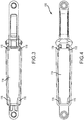
- the fore and aft stops 116, 118 are provided to stop a box magazine from extending too far into an interior cavity 114 of the magazine well of the unit 100 (see FIG. 4 ) and/or the firearm, as well as to reduce a rotational movement of the magazine within the magazine well of the unit 100. More specifically, the fore and aft stops 116, 118 together provide a tight tolerance for attaching a magazine, thereby reducing the tolerance stack-up between the firearm and the cartridge feed components.
- the lever 110 may releasably maintain a magazine attached to the unit 100 in a manner known to those skilled in the art.
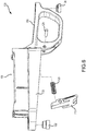
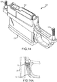
- the lever 110 may be biased towards an engaged position by the spring 120 (see FIG. 1 ) to selectively allow a magazine to be inserted into the magazine well 106. That is, the lever 110 may be biased in an extended position as illustrated in FIG. 5 . Insertion of a magazine 200 may cause the spring 120 to temporarily retract, until the spring 120 extends again to cause the lever 110 to engage a recess in the magazine 200, as illustrated in FIG. 14A .
- the lever 110 is pivoted about the pin 126 (see FIG.
- the lever 110 may be configured to require either a pull motion or a push motion to force disengagement from the magazine 200.
- the magazine well 106 and/or lever 110 may provide sufficient support in some embodiments so as to maintain a magazine attached to, for example, a lower receiver of an AR-15 type or AR-15 variant rifle without allowing significant relative motion between the magazine and the lower receiver (not illustrated).
- the unit 100 may further include a fore fastener interface 122 and an aft fastener interface 124.
- the fastener interfaces 122, 124 may be made of a metallic or other suitably strong material such as a steel, so that the main body 132 of the unit 100 may be made of a polymeric or other lightweight material, such as a reinforced polymer.
- the fastener interfaces 122, 124 may be press fit into the main body 132 to provide a female portion or passage for one or more fasteners 128, 130, as illustrated in FIG. 14 .
- the lever 110 may be made of a metallic material such as a cast steel for strength and durability, and pivotally coupled to the main body 132 using a press fit pin 126.
- the unit 100 may have an opposing side that is a substantially identical mirror image of the first side, although this is not required.
- one or more of the aft stops 118 may be shaped and positioned to provide both a stop flange 134 against which a magazine 200 (not pictured) may abut when installed and an upper portion region 136 for engaging the firearm. That is, the upper portion 112 may generally comprise the upper portion region 136 of the aft stop(s) 118 to suitably engage the firearm.
- FIGS. 10-12 which illustrate a cross section of the unit 100 and details of the fore stops 116 respectively, one or more of the fore stops 116 may be shaped and positioned to provide both a stop flange 138 against which a magazine 200 may abut when installed and an upper portion region 140 for engaging the firearm. That is, the upper portion 112 may generally comprise the upper portion region 140 of the fore stop(s) 116 to suitably engage the firearm.
- the fore and aft stops 116, 118 may be shaped and positioned to position a magazine 200 in the magazine well 106 such that a leading cartridge 300 does not dive excessively relative to a longitudinal axis of the firearm 400, as illustrated in FIG. 14 .
- the upper portion regions 136, 140 of the fore and aft stops 116, 118 provide a clean engagement with the firearm 400, while the stop flanges 134, 138, provide a consistent stop feature for a magazine 200 being installed, thereby reducing the tolerance stack-up and potential for misfeeding of the cartridge.
- the magazine stability is controlled in currently-available aftermarket bottom metals by a combination of the magazine body to magazine well interface, the trigger guard to stock interface, and the trigger guard or magazine well to action interface.
- the unit 100 herein described controls magazine stability using primarily the magazine body to magazine well 106 interface, resulting in a more reliable interface and reducing the chances of misfeeding the cartridge.
- the unit 100 may be shaped so as to limit a tolerance stack-up between the box magazine 200 and the rifle or firearm 400 to consist primarily of an interface between the box magazine 200 and the magazine well 106.
- the unit 100 is configured to provide a tolerance stack-up between the magazine 200 and the firearm 400 that consists of (a) an interface between the magazine 200 and the magazine well 106, (b) an interface between the magazine 200 and the lever 110, and (c) an interface between the magazine well 106 and the firearm 400.
- FIG. 15 is a cross section view illustrating some details of the interface between the unit 100, the magazine 200, and a cartridge 300.
- the fore stop 116 is shown with an upper portion 202 of a box magazine 200 abutting the stop flange 138 in the unit 100.
- the cartridge 300 is also in a feed position, biased towards the feed position by a magazine follower 204.
- FIG. 16 illustrates more detailed aspects of the assembly in FIG. 15 .
- FIGS. 17-18 illustrate a rear portion of the assembly in FIG. 15 .
- the upper portion 202 of the magazine 200 is illustrated abutting the stop flange 134 in the aft stop 118, with the rear portion 304 of the cartridge 300 in a feed position.
- FIG. 19 illustrates the unit 100 installed with a magazine 200 on a bolt action type firearm 400, such as a Remington 700 Long Action type firearm.
- FIGS. 20A-20B illustrate some details of how the unit 100 interfaces with the firearm 400 (note: some components of the firearm 400 are removed for clarity).
- the unit 100 has been illustrated in use with a bolt action type rifle, such as the Remington 700L rifle, the unit 100 could also be used on an AR type rifle platform, and provide substantially the same or similar benefits, such as a reduction in tolerance stack-up, as well as preventing relative movement between the magazine and other components, even if the lower receiver is disconnected.
- detachable box magazines 200 that protrude from the firearm are sometimes used hastily as monopods to help stabilize the weapon.
- soldiers were taught to avoid using the box magazine 200 in this manner, as such use can damage the magazine 200 (direct impact, locking mechanism damage) and cause failures to feed (due to the shifting position of the looser magazines under load).
- some embodiments provide a system 100 and/or method of using a magazine 200 as one would use a monopod. Such embodiments may be useful for non-precision applications, as these type of weapons would typically either use dedicated support (bipod, tripod, separate monopod) mounted in more ideal locations or be set up with more optimal expedient support (sand bags, backpacks, supportive shooting positions, available terrain, etc.).
- the method 2100 includes: removing 2102 a factory bottom metal from the rifle, and coupling 2104 a magazine well unit to the rifle.
- the magazine well unit has (a) an upper portion having a firearm interface; (b) a lower portion shaped to receive a box magazine; (c) a proximal portion; and (d) a distal portion having a magazine well.
- the magazine well may have at least one fore stop and at least one aft stop, the at least one fore stop and the at least one aft stop shaped to prevent the box magazine from passing beyond the upper portion of the magazine well unit.
- At least one of the at least one fore stop or the at least one aft stop comprises an upper portion region having a surface for engaging the firearm.
- the method 2100 may also include coupling a box magazine to the magazine well unit, wherein coupling the box magazine to the magazine well unit comprises causing the box magazine to engage a release lever in the magazine well unit.
- the method 2100 may also include one or more of the following: coupling 2106 the magazine well unit to one of a bolt action type rifle or an AR platform type rifle; coupling 2108 a box magazine to the magazine well unit; causing the at least one fore stop and the at least one aft stop to limit travel of the box magazine relative to the magazine well, or limiting 2110 travel of the magazine (or box magazine) relative to the magazine well; and causing the box magazine to engage the magazine well and a release lever, and no other components of the firearm or magazine well unit.
- the method 2100 includes causing a tolerance stack-up between the magazine and the firearm to consist of (a) an interface between the magazine and the magazine well, (b) an interface between the magazine and the lever, and (c) an interface between the magazine well and the firearm. In some embodiments, the method 2100 includes causing a tolerance stack-up between the magazine and the firearm to consist primarily of an interface between the magazine and the magazine well.
- the method 2100 provides a no-gunsmithing means of retrofitting a rifle with a magazine well unit to reduce tolerance stack-up between a magazine and the rifle.
- no-gunsmithing means shall be understood to mean a means that does not involve drilling or machining features in a factory-provided firearm.
- the present invention provides, among other things, a system and method for using a firearm magazine assembly.
Landscapes
- Engineering & Computer Science (AREA)
- General Engineering & Computer Science (AREA)
- Aiming, Guidance, Guns With A Light Source, Armor, Camouflage, And Targets (AREA)
Claims (15)
- Magazinschachteinheit (100) für eine Schusswaffenaufnahme (402), wobei die Magazinschachteinheit (100) aufweist:einen oberen Abschnitt (112);einen unteren Abschnitt;einen proximalen Abschnitt; undeinen distalen Abschnitt, der einen Magazinschacht (106) hat, um lösbar ein Boxmagazin (200) aufzunehmen; wobeider Magazinschacht (106) wenigstens einen vorderen Stopp (116) und wenigstens einen hinteren Stopp (118) aufweist, wobei der wenigstens eine vordere Stopp (116) und der wenigstens eine hintere Stopp (118) geformt sind, um zu verhindern, dass das Boxmagazin (200) nach oben über eine vorgegebene Position relativ zu dem oberen Abschnitt in der Magazinschachteinheit (100) hinausläuft, indem ein oberer Abschnitt (202) des Boxmagazins (200) anstößt; undder obere Abschnitt der Magazinschachteinheit (100) wenigstens eine Oberfläche zum Eingreifen der Schusswaffenaufnahme hat.
- Einheit (100) nach Anspruch 1, wobei
der proximale Abschnitt einen Abzugsbügel (108) aufweist und/oder der Magazinschacht (106) zwei vordere Stopps (116) und zwei hintere Stopps (118) aufweist. - Einheit (100) nach Anspruch 1, wobei:die wenigstens eine Oberfläche zum Eingreifen der Schusswaffenaufnahme konkav ist.
- Einheit (100) des Anspruchs 1, wobei:der Magazinschacht (106) eine erste Seitenwand, eine zweite Seitenwand um eine erste Endwand und eine zweite Endwand aufweist, wobei die ersten und zweiten Seitenwände und die ersten und zweiten Endwände einen Magazinaufnahmeraum zwischen sich definieren;der wenigstens eine vordere Stopp (116) einen Stopp-Flansch aufweist, der wenigstens mit der ersten Seitenwand, der zweiten Seitenwand oder der zweiten Endband gekoppelt ist; undder wenigstens eine vordere Stopp (116) einen oberen Abschnittsbereich aufweist, der eine Oberfläche zum Eingreifen der Schusswaffenaufnahme, und wobei optional der wenigstens eine hintere Stopp (118) einen Stopp-Flansch aufweist, der wenigstens mit der ersten Seitenwand, der zweiten Seitenwand oder der ersten Endwand gekoppelt ist.
- Einheit (100) nach Anspruch 1, wobei:die Einheit (100) ferner einen Magazinlösehebel zum wahlweise Ineingriffbringen mit dem Boxmagazin (200) hat;wenigstens eine vordere Stopp (116) und der wenigstens eine hintere Stopp (118) Stopp-Flansche aufweisen, um die Verlagerung des Boxmagazins relativ zu dem Magazinschacht (106) zu begrenzen; und wobeidas Boxmagazin (200) nur den Magazinschacht (106) und den Magazinlösehebel eingreift.
- Einheit (100) des Anspruchs 1, wobei:der Magazinschacht (106) eine erste Seitenwand, eine zweite Seitenwand, eine erste Endwand, und eine zweite Endwand aufweist, wobei die erste und zweite Seitenwand und die erste und zweite Endwand einen Magazinaufnahmeraum zwischen sich definieren; undder wenigstens eine hintere Stopp (118) und die erste Endwand einen oberen Abschnitt aufweisen der eine Oberfläche hat, die dazu ausgeformt, eine Schusswaffenaufnahme einzugreifen, und wobei optional der wenigstens eine vordere Stopp (116) und die zweite Endwand einen oberen Abschnitt aufweisen, der eine konkave Oberfläche hat und dazu ausgebildet in die Schusswaffenaufnahme einzugreifen.
- Einheit (100) des Anspruchs 1, wobei:der Magazinschacht (106) eine ersten Seitenwand, eine zweite Seitenwand, eine erste Endwand und eine zweite Endwand aufweist, wobei die erste und zweite Seitenwand und die erste und zweite Endwand einen Magazinaufnahmeraum zwischen sich definieren; undder wenigstens eine vordere Stopp (116) und die zweite Endwand einen oberen Abschnitt aufweisen, der eine konkave Oberfläche hat und dazu ausgeformt ist, in die Schusswaffenaufnahme einzugreifen.
- Einheit (100) des Anspruchs 1, wobei entweder:die Einheit (100) ferner einen Abzugsbügel (100) aufweist und dazu ausgeformt ist, das Boxmagazin (200) mit einem Repetiergewehr verbinden; oderdie Einheit (100) dazu ausgeformt ist, das Boxmagazin (200) mit einer unteren Aufnahme eines AR-Plattform-Gewehrs zu verbinden.
- Einheit (100) des Anspruchs 1, ferner aufweisend:ein Schloss, das dazu ausgebildet ist, das Boxmagazin (200) mit der Einheit (100) gekoppelt zu halten; und wobeidie Einheit (100) geformt ist, um eine Toleranz auf Schichtung zwischen dem Boxmagazin (200) und dem Gewehr derart zu begrenzen, dass es im Wesentlichen auf eine Schnittstelle zwischen dem Boxmagazin (200) und dem Magazinschacht (106) begrenzt istund/oder die Einheit des Anspruchs 1 ferner aufweisend einen Abzugsbügel (108), wobei der Magazinschacht (106) und der Abzugsbügel (108) im Wesentlichen aus einem polymerischen Material bestehen.
- Verfahren zum Nachrüsten eines Gewehrs, wobei das Verfahren aufweist:Entfernen eines Fabrikbodenmetalls von dem Gewehr; undKoppeln einer Magazinschachteinheit mit dem Gewehr, wobei die Magazinschachteinheit aufweist (a) einen oberen Abschnitt, der eine Schnittstelle für eine Schusswaffenaufnahme (b) einen unteren Abschnitt, der geformt ist, um ein Boxmagazin aufzunehmen; (c) einen proximalen Abschnitt; und (d) einen distalen Abschnitt der einen Magazinschacht hat; wobei(i) der Magazinschacht wenigstens einen vorderen Stopp und wenigstens einen hinteren Stopp aufweist, wobei der wenigstens eine vordere Stopp und der wenigstens eine hintere Stopp dazu ausgebildet sind, um zu verhindern, dass das Boxmagazin über eine vorgegebene Position relativ zu dem oberen Abschnitt der Magazinschachteinheit hinaus nach oben ausläuft, indem ein oberer Abschnitt des Boxmagazins anstößt; und(ii) der obere Abschnitt der Magazinschachteinheit wenigstens eine Oberfläche zum Eingreifen in die Schusswaffenaufnahme hat.
- Verfahren des Anspruchs 10, wobei das Gewehr ein Repetier-Gewehr ist und der proximale Abschnitt der Magazinschachteinheit (100) einen Abzugsbügel aufweist, wobei das Verfahren ferner aufweist:Koppeln eines Boxmagazins (200) mit der Magazinschachteinheit (100), wobei das Koppeln des Boxmagazins (200) an der Magazinschachteinheit (100) aufweist: Ineingriffbringen des Boxmagazins (200) mit einem Lösehebel in der Magazinschachteinheit (100).
- Verfahren des Anspruchs 10, ferner aufweisend
Koppeln der Magazinschachteinheit (100) mit entweder einer Aufnahme eines Repetier-Gewehrs oder einer unteren Aufnahme eines AR-Plattform-Gewehrs; Koppeln eines Boxmagazins (200) mit der Magazinschachteinheit (100); grenzende Bewegung des Boxmagazins (200) relativ zu dem Magazinschacht (106) durch den wenigstens einen vorderen Stopp (116) und den wenigstens einen hinteren Stopp (118); und
in Eingriffbringen des Boxmagazins (200) mit dem Magazinschacht (106) und einem Schloss, und einen weiteren Komponenten der Schusswaffe oder Magazinschachteinheit (100) und/oder
Begrenzen einer Toleranzaufschichtung zwischen dem Magazin und der Schusswaffe auf (a) eine Schnittstelle zwischen dem Magazin und dem Magazinschacht, (b) eine Schnittstelle zwischen dem Magazin und dem Schloss, und (c) eine Schnittstelle zwischen dem Magazinschacht und der Waffenaufnahme. - Verfahren des Anspruchs 10, ferner aufweisend:Begrenzen der Toleranzaufschichtung zwischen dem Magazin und der Schusswaffe auf primär eine Schnittstelle zwischen dem Magazin und dem Magazinschacht.
- Umrüstbausatz für eine Repetierschusswaffe, wobei der Umrüstbausatz aufweist:die Magazinschachteinheit des Anspruchs 1mit (a) dem oberen Abschnitt, der eine Schnittstelle für eine Schusswaffenaufnahme hat, (b) dem unteren Abschnitt, (c) dem proximalen Abschnitt, der einen Abzugsbügel hat, (d) dem distalen Abschnitt, und (e) einem Hebel zum lösbaren Koppelthalten des Magazins mit dem Magazinschacht; wobei wenigstens eine vordere Stopp oder der wenigstens eine hintere Stopp eine Flansch-Oberfläche aufweist, um das Boxmagazin daran zu hintern über eine vorgegebene Position hinaus relativ zu dem oberen Abschnitt-Magazinschachteinheit hinaus zu laufen; und wobeider Umrüstbausatz dazu ausgebildet ist, ein Fabrikbodenmetall in der Repetierschusswaffe zu ersetzen, und um eine Toleranzaufschichtung bereit zu stellen zwischen dem Magazin und der Schusswaffe, wobei die Toleranzaufschichtung umfasst (a) eine Schnittstelle zwischen dem Magazin und dem Magazinschacht (b) eine Schnittstelle zwischen dem Magazin und dem Hebel, und (c) eine Schnittstelle zwischen dem Magazinschacht und der Schusswaffenaufnahme.
- Umrüstbausatz des Anspruchs 14; wobei
die Magazinschachteinheit dazu geformt ist, ein Bodenmetall in einem RepetierGewehr zu ersetzen; und
der obere Abschnitt eine Oberfläche zum Eingreifen in eine Schusswaffenaufnahme hat.
Applications Claiming Priority (1)
| Application Number | Priority Date | Filing Date | Title |
|---|---|---|---|
| US201562199597P | 2015-07-31 | 2015-07-31 |
Publications (2)
| Publication Number | Publication Date |
|---|---|
| EP3124910A1 EP3124910A1 (de) | 2017-02-01 |
| EP3124910B1 true EP3124910B1 (de) | 2019-02-20 |
Family
ID=56557635
Family Applications (1)
| Application Number | Title | Priority Date | Filing Date |
|---|---|---|---|
| EP16182255.6A Not-in-force EP3124910B1 (de) | 2015-07-31 | 2016-08-01 | Magazinschacht für eine feuerwaffe |
Country Status (2)
| Country | Link |
|---|---|
| US (2) | US10101102B2 (de) |
| EP (1) | EP3124910B1 (de) |
Cited By (1)
| Publication number | Priority date | Publication date | Assignee | Title |
|---|---|---|---|---|
| USD1004037S1 (en) | 2021-07-23 | 2023-11-07 | 22 Evolution Llc | Trigger guard for a firearm |
Families Citing this family (22)
| Publication number | Priority date | Publication date | Assignee | Title |
|---|---|---|---|---|
| US10739095B2 (en) | 2015-12-01 | 2020-08-11 | Mean L.L.C. | Firearm operating system |
| US10697724B2 (en) * | 2017-05-16 | 2020-06-30 | RedSnake Enterprises, LLC | Bottom metal for a detachable box magazine |
| US10571210B2 (en) * | 2017-11-29 | 2020-02-25 | Chad Amodio | Trigger guard for a firearm comprising a projection |
| EP3737907B1 (de) | 2018-01-09 | 2024-08-21 | Sturm, Ruger & Company, Inc. | Modulares magazinschachteinführsystem für schusswaffe |
| USD877284S1 (en) * | 2018-11-20 | 2020-03-03 | Shih-Che Hu | Gun body |
| USD877844S1 (en) * | 2018-11-20 | 2020-03-10 | Shih-Che Hu | Gun body |
| USD877283S1 (en) * | 2018-11-20 | 2020-03-03 | Shih-Che Hu | Gun body |
| US10969184B2 (en) * | 2019-01-10 | 2021-04-06 | Daniel Defense, Inc. | Bolt action firearm receiver assemblies |
| USD897479S1 (en) * | 2019-01-21 | 2020-09-29 | Daniel Defense, Inc. | Trigger guard and magazine latch assembly |
| USD877845S1 (en) * | 2019-03-03 | 2020-03-10 | Shih-Che Hu | Gun body |
| USD877846S1 (en) * | 2019-03-05 | 2020-03-10 | Shih-Che Hu | Gun body |
| US11280570B2 (en) | 2019-03-11 | 2022-03-22 | James Matthew Underwood | Firearm operating mechanisms and bolt release |
| US11371789B2 (en) | 2019-08-06 | 2022-06-28 | James Matthew Underwood | Roller delayed firearm operating system |
| US11543195B2 (en) | 2020-07-03 | 2023-01-03 | James Matthew Underwood | Roller and bearing delayed firearm operating systems |
| US11846476B2 (en) | 2021-10-07 | 2023-12-19 | James Matthew Underwood | Ejector for firearm |
| USD998742S1 (en) * | 2023-05-17 | 2023-09-12 | Noah Zimner | Ruger American 7.62×39 magazine well |
| US20250123067A1 (en) * | 2023-10-13 | 2025-04-17 | James Matthew Underwood | Modular magazine assemblies |
| USD1108573S1 (en) | 2023-10-16 | 2026-01-06 | Evolved Gear Llc | Firearm |
| USD1108572S1 (en) | 2023-10-16 | 2026-01-06 | Evolved Gear Llc | Firearm |
| USD1110455S1 (en) | 2023-10-16 | 2026-01-27 | Evolved Gear Llc | Firearm |
| US20240133651A1 (en) * | 2023-12-01 | 2024-04-25 | Shawn Batten | Rifle Tripod Support Assembly |
| USD1115997S1 (en) * | 2024-06-03 | 2026-03-03 | Syndicus USA Inc. | Firearm magazine well |
Family Cites Families (52)
| Publication number | Priority date | Publication date | Assignee | Title |
|---|---|---|---|---|
| US2997803A (en) | 1959-06-19 | 1961-08-29 | Clyde M Florence | Removable magazine unit for bolt action rifle |
| US2956363A (en) * | 1959-06-23 | 1960-10-18 | Alfred L Montana | Side cam magazine catch for firearms |
| US3574264A (en) * | 1969-07-14 | 1971-04-13 | Ernest P Simmons Sr | Magazine assembly for automatic rifles |
| US3803739A (en) * | 1972-07-28 | 1974-04-16 | J Troutman | Magazine kit for repeating rifles |
| US4237638A (en) | 1978-08-04 | 1980-12-09 | Trexler Gene D | Box magazine replacement kit for bolt action rifles |
| US4505182A (en) * | 1980-12-11 | 1985-03-19 | Chartered Industries Of Singapore Private Ltd. | Firearm trigger mechanism |
| US4475437A (en) * | 1980-12-11 | 1984-10-09 | Chartered Industries Of Singapore Private Limited | Sear actuator |
| DE19743557C1 (de) | 1997-10-01 | 1999-03-25 | Sig Schweiz Industrieges | Magazin-Arretierung an einer Handfeuerwaffe |
| DE102006009895B3 (de) | 2006-03-03 | 2007-07-12 | S.A.T. Swiss Arms Technology Ag | Steckmagazin einer Handfeuerwaffe |
| US9151553B2 (en) | 2007-01-10 | 2015-10-06 | Smith & Wesson Corp. | Bolt action firearm and its method of assembly |
| DE102009037899A1 (de) | 2009-08-19 | 2011-02-24 | Rheinmetall Waffe Munition Gmbh | Keilverschluss einer Rohrwaffe |
| US20110173859A1 (en) | 2010-01-15 | 2011-07-21 | Smith & Wesson Corp. | Removable trigger guard |
| US8434253B2 (en) | 2010-03-29 | 2013-05-07 | Randy Cain | Magazine release latch and trigger guard |
| US9091499B2 (en) * | 2010-04-08 | 2015-07-28 | 22 Evolution Llc | Bolt hold open actuator for use with AR-15/M16 type firearms |
| US20120085009A1 (en) | 2010-04-09 | 2012-04-12 | Crow Larry P | Rifle bedding block with integral magazine and trigger guard assembly |
| USD640766S1 (en) | 2010-05-24 | 2011-06-28 | Joplin Jered S | Firearm trigger guard and magazine release |
| US8397416B2 (en) | 2010-09-28 | 2013-03-19 | Smith & Wesson Corp. | Multi-caliber bolt-action rifle and components |
| GB2485166B (en) | 2010-11-02 | 2014-11-19 | Rodney Goodman | A firearm stock |
| US8464455B2 (en) | 2011-01-07 | 2013-06-18 | Sturm, Ruger & Company, Inc. | Lockable safety for firearm |
| US9631885B2 (en) * | 2011-01-13 | 2017-04-25 | J. Allen Enterprises, Inc. | Rifle stock assembly for different barreled receivers |
| US8931200B2 (en) | 2011-02-02 | 2015-01-13 | Nathan Pratt | Slide-lock engagement device |
| US8104209B1 (en) * | 2011-02-03 | 2012-01-31 | Krow Innovation, Inc. | Dynamic latch for a tube mounted magazine well |
| US8832987B2 (en) | 2011-10-26 | 2014-09-16 | Michael A. Addis | Systems and methods for aiding the insertion of detachable firearm magazines |
| WO2013090749A1 (en) | 2011-12-14 | 2013-06-20 | Sturm, Ruger & Company, Inc. | Stock bedding system for firearm |
| US8904692B2 (en) | 2012-01-06 | 2014-12-09 | Brookshire Tool & Mfg Co., Inc. | Butt pad apparatus for a firearm |
| US8931393B1 (en) | 2012-02-23 | 2015-01-13 | Jeff Vincent | Replacement stock system for rifle |
| DE202013012776U1 (de) | 2012-03-22 | 2019-08-22 | Frederik Wilhelm Du Plooy | Gewehr-Hinterschaft |
| US9091505B1 (en) | 2012-04-10 | 2015-07-28 | Vincent P. Battaglia | Solid chassis rifle |
| US8950097B2 (en) | 2012-05-01 | 2015-02-10 | Edward A. Sugg | Automatic weapon magazine, charging handle, bolt carrier, bolt catch, scope, and bolt features and methods of operation |
| US9140506B2 (en) | 2012-07-31 | 2015-09-22 | Lwrc International Llc | Firearm receiver assembly |
| DE202012008104U1 (de) | 2012-08-24 | 2013-01-29 | Styria Arms - Mayerl | Abzugsbügel für Schusswaffen mit herausnehmbaren Magazin |
| US8782943B2 (en) | 2012-10-26 | 2014-07-22 | Ra Brands, L.L.C. | Quick detach barrel mounting system |
| EP2943733B1 (de) | 2013-01-10 | 2019-02-27 | Sturm, Ruger & Company, Inc. | Austauschbares schaftsystem für feuerwaffen |
| US9513077B2 (en) * | 2013-01-11 | 2016-12-06 | Howa Machnery, Ltd. | Magazine lock and portable firearm |
| US8984790B2 (en) | 2013-01-11 | 2015-03-24 | Sig Sauer, Inc. | Adjustable cheek rest |
| US8935872B2 (en) | 2013-02-05 | 2015-01-20 | Smith & Wesson Corp. | Firearm having magazine safety |
| DE102013102198A1 (de) | 2013-03-06 | 2014-09-11 | L&O Hunting Group GmbH | Gewehrschaft |
| US8789305B1 (en) | 2013-06-26 | 2014-07-29 | American Tactical Imports, Inc. | Hybrid lower receiver for a rifle |
| AT514445B1 (de) * | 2013-06-27 | 2015-05-15 | Weilharter Rene | Schusswaffe |
| US10767943B2 (en) | 2013-06-28 | 2020-09-08 | David K Roberts | Hybrid polymer lower receivers for firearms and metal threaded inserts, kits and methods therefor |
| US9383162B2 (en) | 2013-07-02 | 2016-07-05 | David Joel Spykerman | Adjustable firearm |
| US9267750B1 (en) | 2013-08-17 | 2016-02-23 | Superior Shooting Systems, Inc | Drop-in adjustable trigger assembly with camming safety linkage |
| US9003685B1 (en) * | 2013-08-27 | 2015-04-14 | George Huang | Hinged trigger guard |
| US9857132B2 (en) | 2014-01-07 | 2018-01-02 | Pro Mag Mfg., Inc. | Rifle stock |
| USD744055S1 (en) | 2014-04-25 | 2015-11-24 | Donald F. Bitz | Gun stock with an interchangeable barrel channel in the forend |
| USD745623S1 (en) | 2014-05-19 | 2015-12-15 | Nightstrike, LLC | Forward grip for a rifle barrel |
| USD745940S1 (en) | 2014-05-28 | 2015-12-22 | Nightstrike, LLC | Forward grip for a rifle barrel |
| WO2015186017A1 (en) | 2014-06-04 | 2015-12-10 | Salzani Alberto | Firearms with automatic safety lock |
| US20150377584A1 (en) | 2014-06-25 | 2015-12-31 | Ati Ip, Llc | Forend-mounted heatshield arrangement for firearms |
| WO2015200588A1 (en) | 2014-06-26 | 2015-12-30 | Sturm, Ruger & Company, Inc. | Firearm safety mechanism |
| US9341436B2 (en) | 2014-08-13 | 2016-05-17 | Kenneth A Frankel | Gun assembly including gun action mated to gunstock by at least three zones of intentional interference fit |
| US20160348992A1 (en) * | 2015-05-29 | 2016-12-01 | Richard J. Tisone | Ammunition magazine configured for automatic ejection |
-
2016
- 2016-07-28 US US15/222,526 patent/US10101102B2/en active Active
- 2016-08-01 EP EP16182255.6A patent/EP3124910B1/de not_active Not-in-force
-
2018
- 2018-09-19 US US16/135,264 patent/US10996008B2/en active Active
Non-Patent Citations (1)
| Title |
|---|
| None * |
Cited By (1)
| Publication number | Priority date | Publication date | Assignee | Title |
|---|---|---|---|---|
| USD1004037S1 (en) | 2021-07-23 | 2023-11-07 | 22 Evolution Llc | Trigger guard for a firearm |
Also Published As
| Publication number | Publication date |
|---|---|
| US10101102B2 (en) | 2018-10-16 |
| EP3124910A1 (de) | 2017-02-01 |
| US10996008B2 (en) | 2021-05-04 |
| US20170030667A1 (en) | 2017-02-02 |
| US20190107347A1 (en) | 2019-04-11 |
Similar Documents
| Publication | Publication Date | Title |
|---|---|---|
| EP3124910B1 (de) | Magazinschacht für eine feuerwaffe | |
| US11578943B2 (en) | Firearm barrel tray, stock, and related methods | |
| EP3869141B1 (de) | Verfahren und vorrichtung für einen optischen adapter für einen schusswaffenschieber | |
| US7162823B2 (en) | Firearm stock connector | |
| US10161712B2 (en) | Rifle stock assembly for different barreled receivers | |
| US8539708B2 (en) | Barrel mounting and retention mechanism | |
| US10578396B2 (en) | Modular grenade launcher system | |
| US7810271B2 (en) | Modular rifle systems and methods | |
| US8819982B2 (en) | Precision rifle chassis system | |
| US8429844B2 (en) | Modular firearm stock system | |
| US8291805B1 (en) | Quick-attach locking device for a flash hider | |
| US20190101350A1 (en) | Compensators for firearms, and related methods | |
| EP3489611B1 (de) | Auswechselbaren platten für eine feuerwaffe | |
| US6889463B2 (en) | Rifle comprising a stock, a forearm and a barrel | |
| US20120167433A1 (en) | Modular automatic or semi-automatic rifle | |
| WO2015106163A1 (en) | Firearm magazine adapter and release assembly | |
| US20210048261A1 (en) | Firearm Breech Cover Interlock | |
| US10648769B2 (en) | Handgun grip module with a reinforcing bracket | |
| US20190285374A1 (en) | Firearm Magazine | |
| US12504243B2 (en) | Magazine well assembly | |
| US12169111B2 (en) | Ambidextrous charging handle | |
| EP2383537A1 (de) | Montierplatte zur lösbaren Montage eines Visiers an einer Schusswaffe | |
| US20250283689A1 (en) | Handguard mounting system |
Legal Events
| Date | Code | Title | Description |
|---|---|---|---|
| PUAI | Public reference made under article 153(3) epc to a published international application that has entered the european phase |
Free format text: ORIGINAL CODE: 0009012 |
|
| STAA | Information on the status of an ep patent application or granted ep patent |
Free format text: STATUS: THE APPLICATION HAS BEEN PUBLISHED |
|
| AK | Designated contracting states |
Kind code of ref document: A1 Designated state(s): AL AT BE BG CH CY CZ DE DK EE ES FI FR GB GR HR HU IE IS IT LI LT LU LV MC MK MT NL NO PL PT RO RS SE SI SK SM TR |
|
| AX | Request for extension of the european patent |
Extension state: BA ME |
|
| STAA | Information on the status of an ep patent application or granted ep patent |
Free format text: STATUS: REQUEST FOR EXAMINATION WAS MADE |
|
| 17P | Request for examination filed |
Effective date: 20170616 |
|
| RBV | Designated contracting states (corrected) |
Designated state(s): AL AT BE BG CH CY CZ DE DK EE ES FI FR GB GR HR HU IE IS IT LI LT LU LV MC MK MT NL NO PL PT RO RS SE SI SK SM TR |
|
| GRAP | Despatch of communication of intention to grant a patent |
Free format text: ORIGINAL CODE: EPIDOSNIGR1 |
|
| STAA | Information on the status of an ep patent application or granted ep patent |
Free format text: STATUS: GRANT OF PATENT IS INTENDED |
|
| INTG | Intention to grant announced |
Effective date: 20181015 |
|
| GRAS | Grant fee paid |
Free format text: ORIGINAL CODE: EPIDOSNIGR3 |
|
| GRAA | (expected) grant |
Free format text: ORIGINAL CODE: 0009210 |
|
| STAA | Information on the status of an ep patent application or granted ep patent |
Free format text: STATUS: THE PATENT HAS BEEN GRANTED |
|
| AK | Designated contracting states |
Kind code of ref document: B1 Designated state(s): AL AT BE BG CH CY CZ DE DK EE ES FI FR GB GR HR HU IE IS IT LI LT LU LV MC MK MT NL NO PL PT RO RS SE SI SK SM TR |
|
| REG | Reference to a national code |
Ref country code: GB Ref legal event code: FG4D |
|
| REG | Reference to a national code |
Ref country code: CH Ref legal event code: EP |
|
| REG | Reference to a national code |
Ref country code: DE Ref legal event code: R096 Ref document number: 602016010037 Country of ref document: DE |
|
| REG | Reference to a national code |
Ref country code: AT Ref legal event code: REF Ref document number: 1098761 Country of ref document: AT Kind code of ref document: T Effective date: 20190315 |
|
| REG | Reference to a national code |
Ref country code: IE Ref legal event code: FG4D |
|
| REG | Reference to a national code |
Ref country code: LT Ref legal event code: MG4D |
|
| REG | Reference to a national code |
Ref country code: NL Ref legal event code: MP Effective date: 20190220 |
|
| PG25 | Lapsed in a contracting state [announced via postgrant information from national office to epo] |
Ref country code: PT Free format text: LAPSE BECAUSE OF FAILURE TO SUBMIT A TRANSLATION OF THE DESCRIPTION OR TO PAY THE FEE WITHIN THE PRESCRIBED TIME-LIMIT Effective date: 20190620 Ref country code: SE Free format text: LAPSE BECAUSE OF FAILURE TO SUBMIT A TRANSLATION OF THE DESCRIPTION OR TO PAY THE FEE WITHIN THE PRESCRIBED TIME-LIMIT Effective date: 20190220 Ref country code: LT Free format text: LAPSE BECAUSE OF FAILURE TO SUBMIT A TRANSLATION OF THE DESCRIPTION OR TO PAY THE FEE WITHIN THE PRESCRIBED TIME-LIMIT Effective date: 20190220 Ref country code: NO Free format text: LAPSE BECAUSE OF FAILURE TO SUBMIT A TRANSLATION OF THE DESCRIPTION OR TO PAY THE FEE WITHIN THE PRESCRIBED TIME-LIMIT Effective date: 20190520 Ref country code: FI Free format text: LAPSE BECAUSE OF FAILURE TO SUBMIT A TRANSLATION OF THE DESCRIPTION OR TO PAY THE FEE WITHIN THE PRESCRIBED TIME-LIMIT Effective date: 20190220 |
|
| PG25 | Lapsed in a contracting state [announced via postgrant information from national office to epo] |
Ref country code: GR Free format text: LAPSE BECAUSE OF FAILURE TO SUBMIT A TRANSLATION OF THE DESCRIPTION OR TO PAY THE FEE WITHIN THE PRESCRIBED TIME-LIMIT Effective date: 20190521 Ref country code: IS Free format text: LAPSE BECAUSE OF FAILURE TO SUBMIT A TRANSLATION OF THE DESCRIPTION OR TO PAY THE FEE WITHIN THE PRESCRIBED TIME-LIMIT Effective date: 20190620 Ref country code: RS Free format text: LAPSE BECAUSE OF FAILURE TO SUBMIT A TRANSLATION OF THE DESCRIPTION OR TO PAY THE FEE WITHIN THE PRESCRIBED TIME-LIMIT Effective date: 20190220 Ref country code: BG Free format text: LAPSE BECAUSE OF FAILURE TO SUBMIT A TRANSLATION OF THE DESCRIPTION OR TO PAY THE FEE WITHIN THE PRESCRIBED TIME-LIMIT Effective date: 20190520 Ref country code: NL Free format text: LAPSE BECAUSE OF FAILURE TO SUBMIT A TRANSLATION OF THE DESCRIPTION OR TO PAY THE FEE WITHIN THE PRESCRIBED TIME-LIMIT Effective date: 20190220 Ref country code: LV Free format text: LAPSE BECAUSE OF FAILURE TO SUBMIT A TRANSLATION OF THE DESCRIPTION OR TO PAY THE FEE WITHIN THE PRESCRIBED TIME-LIMIT Effective date: 20190220 Ref country code: HR Free format text: LAPSE BECAUSE OF FAILURE TO SUBMIT A TRANSLATION OF THE DESCRIPTION OR TO PAY THE FEE WITHIN THE PRESCRIBED TIME-LIMIT Effective date: 20190220 |
|
| REG | Reference to a national code |
Ref country code: AT Ref legal event code: MK05 Ref document number: 1098761 Country of ref document: AT Kind code of ref document: T Effective date: 20190220 |
|
| PG25 | Lapsed in a contracting state [announced via postgrant information from national office to epo] |
Ref country code: IT Free format text: LAPSE BECAUSE OF FAILURE TO SUBMIT A TRANSLATION OF THE DESCRIPTION OR TO PAY THE FEE WITHIN THE PRESCRIBED TIME-LIMIT Effective date: 20190220 Ref country code: RO Free format text: LAPSE BECAUSE OF FAILURE TO SUBMIT A TRANSLATION OF THE DESCRIPTION OR TO PAY THE FEE WITHIN THE PRESCRIBED TIME-LIMIT Effective date: 20190220 Ref country code: CZ Free format text: LAPSE BECAUSE OF FAILURE TO SUBMIT A TRANSLATION OF THE DESCRIPTION OR TO PAY THE FEE WITHIN THE PRESCRIBED TIME-LIMIT Effective date: 20190220 Ref country code: AL Free format text: LAPSE BECAUSE OF FAILURE TO SUBMIT A TRANSLATION OF THE DESCRIPTION OR TO PAY THE FEE WITHIN THE PRESCRIBED TIME-LIMIT Effective date: 20190220 Ref country code: SK Free format text: LAPSE BECAUSE OF FAILURE TO SUBMIT A TRANSLATION OF THE DESCRIPTION OR TO PAY THE FEE WITHIN THE PRESCRIBED TIME-LIMIT Effective date: 20190220 Ref country code: ES Free format text: LAPSE BECAUSE OF FAILURE TO SUBMIT A TRANSLATION OF THE DESCRIPTION OR TO PAY THE FEE WITHIN THE PRESCRIBED TIME-LIMIT Effective date: 20190220 Ref country code: DK Free format text: LAPSE BECAUSE OF FAILURE TO SUBMIT A TRANSLATION OF THE DESCRIPTION OR TO PAY THE FEE WITHIN THE PRESCRIBED TIME-LIMIT Effective date: 20190220 Ref country code: EE Free format text: LAPSE BECAUSE OF FAILURE TO SUBMIT A TRANSLATION OF THE DESCRIPTION OR TO PAY THE FEE WITHIN THE PRESCRIBED TIME-LIMIT Effective date: 20190220 |
|
| REG | Reference to a national code |
Ref country code: DE Ref legal event code: R097 Ref document number: 602016010037 Country of ref document: DE |
|
| PG25 | Lapsed in a contracting state [announced via postgrant information from national office to epo] |
Ref country code: SM Free format text: LAPSE BECAUSE OF FAILURE TO SUBMIT A TRANSLATION OF THE DESCRIPTION OR TO PAY THE FEE WITHIN THE PRESCRIBED TIME-LIMIT Effective date: 20190220 Ref country code: PL Free format text: LAPSE BECAUSE OF FAILURE TO SUBMIT A TRANSLATION OF THE DESCRIPTION OR TO PAY THE FEE WITHIN THE PRESCRIBED TIME-LIMIT Effective date: 20190220 |
|
| PLBE | No opposition filed within time limit |
Free format text: ORIGINAL CODE: 0009261 |
|
| STAA | Information on the status of an ep patent application or granted ep patent |
Free format text: STATUS: NO OPPOSITION FILED WITHIN TIME LIMIT |
|
| PG25 | Lapsed in a contracting state [announced via postgrant information from national office to epo] |
Ref country code: AT Free format text: LAPSE BECAUSE OF FAILURE TO SUBMIT A TRANSLATION OF THE DESCRIPTION OR TO PAY THE FEE WITHIN THE PRESCRIBED TIME-LIMIT Effective date: 20190220 |
|
| 26N | No opposition filed |
Effective date: 20191121 |
|
| PG25 | Lapsed in a contracting state [announced via postgrant information from national office to epo] |
Ref country code: SI Free format text: LAPSE BECAUSE OF FAILURE TO SUBMIT A TRANSLATION OF THE DESCRIPTION OR TO PAY THE FEE WITHIN THE PRESCRIBED TIME-LIMIT Effective date: 20190220 |
|
| REG | Reference to a national code |
Ref country code: DE Ref legal event code: R119 Ref document number: 602016010037 Country of ref document: DE |
|
| PG25 | Lapsed in a contracting state [announced via postgrant information from national office to epo] |
Ref country code: TR Free format text: LAPSE BECAUSE OF FAILURE TO SUBMIT A TRANSLATION OF THE DESCRIPTION OR TO PAY THE FEE WITHIN THE PRESCRIBED TIME-LIMIT Effective date: 20190220 |
|
| PG25 | Lapsed in a contracting state [announced via postgrant information from national office to epo] |
Ref country code: LU Free format text: LAPSE BECAUSE OF NON-PAYMENT OF DUE FEES Effective date: 20190801 Ref country code: CH Free format text: LAPSE BECAUSE OF NON-PAYMENT OF DUE FEES Effective date: 20190831 Ref country code: LI Free format text: LAPSE BECAUSE OF NON-PAYMENT OF DUE FEES Effective date: 20190831 Ref country code: MC Free format text: LAPSE BECAUSE OF FAILURE TO SUBMIT A TRANSLATION OF THE DESCRIPTION OR TO PAY THE FEE WITHIN THE PRESCRIBED TIME-LIMIT Effective date: 20190220 |
|
| REG | Reference to a national code |
Ref country code: BE Ref legal event code: MM Effective date: 20190831 |
|
| PG25 | Lapsed in a contracting state [announced via postgrant information from national office to epo] |
Ref country code: IE Free format text: LAPSE BECAUSE OF NON-PAYMENT OF DUE FEES Effective date: 20190801 Ref country code: DE Free format text: LAPSE BECAUSE OF NON-PAYMENT OF DUE FEES Effective date: 20200303 Ref country code: FR Free format text: LAPSE BECAUSE OF NON-PAYMENT OF DUE FEES Effective date: 20190831 |
|
| PG25 | Lapsed in a contracting state [announced via postgrant information from national office to epo] |
Ref country code: BE Free format text: LAPSE BECAUSE OF NON-PAYMENT OF DUE FEES Effective date: 20190831 |
|
| GBPC | Gb: european patent ceased through non-payment of renewal fee |
Effective date: 20200801 |
|
| PG25 | Lapsed in a contracting state [announced via postgrant information from national office to epo] |
Ref country code: CY Free format text: LAPSE BECAUSE OF FAILURE TO SUBMIT A TRANSLATION OF THE DESCRIPTION OR TO PAY THE FEE WITHIN THE PRESCRIBED TIME-LIMIT Effective date: 20190220 |
|
| PG25 | Lapsed in a contracting state [announced via postgrant information from national office to epo] |
Ref country code: MT Free format text: LAPSE BECAUSE OF FAILURE TO SUBMIT A TRANSLATION OF THE DESCRIPTION OR TO PAY THE FEE WITHIN THE PRESCRIBED TIME-LIMIT Effective date: 20190220 Ref country code: HU Free format text: LAPSE BECAUSE OF FAILURE TO SUBMIT A TRANSLATION OF THE DESCRIPTION OR TO PAY THE FEE WITHIN THE PRESCRIBED TIME-LIMIT; INVALID AB INITIO Effective date: 20160801 |
|
| PG25 | Lapsed in a contracting state [announced via postgrant information from national office to epo] |
Ref country code: GB Free format text: LAPSE BECAUSE OF NON-PAYMENT OF DUE FEES Effective date: 20200801 |
|
| PG25 | Lapsed in a contracting state [announced via postgrant information from national office to epo] |
Ref country code: MK Free format text: LAPSE BECAUSE OF FAILURE TO SUBMIT A TRANSLATION OF THE DESCRIPTION OR TO PAY THE FEE WITHIN THE PRESCRIBED TIME-LIMIT Effective date: 20190220 |