EP3124996A1 - Fehldetektionrückhalteschaltung zur laserentfernungsmesser - Google Patents
Fehldetektionrückhalteschaltung zur laserentfernungsmesser Download PDFInfo
- Publication number
- EP3124996A1 EP3124996A1 EP16182073.3A EP16182073A EP3124996A1 EP 3124996 A1 EP3124996 A1 EP 3124996A1 EP 16182073 A EP16182073 A EP 16182073A EP 3124996 A1 EP3124996 A1 EP 3124996A1
- Authority
- EP
- European Patent Office
- Prior art keywords
- light
- time
- threshold
- fog
- erroneous detection
- Prior art date
- Legal status (The legal status is an assumption and is not a legal conclusion. Google has not performed a legal analysis and makes no representation as to the accuracy of the status listed.)
- Withdrawn
Links
- 238000001514 detection method Methods 0.000 title claims abstract description 79
- 230000000452 restraining effect Effects 0.000 title claims description 17
- 238000005259 measurement Methods 0.000 claims abstract description 42
- 230000003321 amplification Effects 0.000 claims abstract description 13
- 238000003199 nucleic acid amplification method Methods 0.000 claims abstract description 13
- 230000008859 change Effects 0.000 claims description 6
- 230000007423 decrease Effects 0.000 claims description 6
- 230000007246 mechanism Effects 0.000 description 9
- 238000000034 method Methods 0.000 description 8
- 230000008569 process Effects 0.000 description 8
- 238000010586 diagram Methods 0.000 description 6
- 230000000630 rising effect Effects 0.000 description 6
- 230000000694 effects Effects 0.000 description 3
- 238000012545 processing Methods 0.000 description 2
- XLYOFNOQVPJJNP-UHFFFAOYSA-N water Substances O XLYOFNOQVPJJNP-UHFFFAOYSA-N 0.000 description 2
- 235000015256 Chionanthus virginicus Nutrition 0.000 description 1
- 241000234271 Galanthus Species 0.000 description 1
- 230000002411 adverse Effects 0.000 description 1
- 239000002131 composite material Substances 0.000 description 1
- 238000007796 conventional method Methods 0.000 description 1
- 238000012937 correction Methods 0.000 description 1
- 239000000284 extract Substances 0.000 description 1
- 230000006872 improvement Effects 0.000 description 1
- 238000009434 installation Methods 0.000 description 1
- 238000012986 modification Methods 0.000 description 1
- 230000004048 modification Effects 0.000 description 1
- 230000003287 optical effect Effects 0.000 description 1
- 239000004065 semiconductor Substances 0.000 description 1
Images


Classifications
-
- G—PHYSICS
- G01—MEASURING; TESTING
- G01S—RADIO DIRECTION-FINDING; RADIO NAVIGATION; DETERMINING DISTANCE OR VELOCITY BY USE OF RADIO WAVES; LOCATING OR PRESENCE-DETECTING BY USE OF THE REFLECTION OR RERADIATION OF RADIO WAVES; ANALOGOUS ARRANGEMENTS USING OTHER WAVES
- G01S7/00—Details of systems according to groups G01S13/00, G01S15/00, G01S17/00
- G01S7/48—Details of systems according to groups G01S13/00, G01S15/00, G01S17/00 of systems according to group G01S17/00
- G01S7/483—Details of pulse systems
- G01S7/486—Receivers
- G01S7/4868—Controlling received signal intensity or exposure of sensor
-
- G—PHYSICS
- G01—MEASURING; TESTING
- G01S—RADIO DIRECTION-FINDING; RADIO NAVIGATION; DETERMINING DISTANCE OR VELOCITY BY USE OF RADIO WAVES; LOCATING OR PRESENCE-DETECTING BY USE OF THE REFLECTION OR RERADIATION OF RADIO WAVES; ANALOGOUS ARRANGEMENTS USING OTHER WAVES
- G01S17/00—Systems using the reflection or reradiation of electromagnetic waves other than radio waves, e.g. lidar systems
- G01S17/02—Systems using the reflection of electromagnetic waves other than radio waves
- G01S17/04—Systems determining the presence of a target
-
- G—PHYSICS
- G01—MEASURING; TESTING
- G01S—RADIO DIRECTION-FINDING; RADIO NAVIGATION; DETERMINING DISTANCE OR VELOCITY BY USE OF RADIO WAVES; LOCATING OR PRESENCE-DETECTING BY USE OF THE REFLECTION OR RERADIATION OF RADIO WAVES; ANALOGOUS ARRANGEMENTS USING OTHER WAVES
- G01S17/00—Systems using the reflection or reradiation of electromagnetic waves other than radio waves, e.g. lidar systems
- G01S17/02—Systems using the reflection of electromagnetic waves other than radio waves
- G01S17/06—Systems determining position data of a target
- G01S17/08—Systems determining position data of a target for measuring distance only
- G01S17/10—Systems determining position data of a target for measuring distance only using transmission of interrupted, pulse-modulated waves
-
- G—PHYSICS
- G01—MEASURING; TESTING
- G01S—RADIO DIRECTION-FINDING; RADIO NAVIGATION; DETERMINING DISTANCE OR VELOCITY BY USE OF RADIO WAVES; LOCATING OR PRESENCE-DETECTING BY USE OF THE REFLECTION OR RERADIATION OF RADIO WAVES; ANALOGOUS ARRANGEMENTS USING OTHER WAVES
- G01S7/00—Details of systems according to groups G01S13/00, G01S15/00, G01S17/00
- G01S7/48—Details of systems according to groups G01S13/00, G01S15/00, G01S17/00 of systems according to group G01S17/00
- G01S7/483—Details of pulse systems
- G01S7/486—Receivers
- G01S7/4865—Time delay measurement, e.g. time-of-flight measurement, time of arrival measurement or determining the exact position of a peak
-
- G—PHYSICS
- G01—MEASURING; TESTING
- G01S—RADIO DIRECTION-FINDING; RADIO NAVIGATION; DETERMINING DISTANCE OR VELOCITY BY USE OF RADIO WAVES; LOCATING OR PRESENCE-DETECTING BY USE OF THE REFLECTION OR RERADIATION OF RADIO WAVES; ANALOGOUS ARRANGEMENTS USING OTHER WAVES
- G01S7/00—Details of systems according to groups G01S13/00, G01S15/00, G01S17/00
- G01S7/48—Details of systems according to groups G01S13/00, G01S15/00, G01S17/00 of systems according to group G01S17/00
- G01S7/483—Details of pulse systems
- G01S7/486—Receivers
- G01S7/487—Extracting wanted echo signals, e.g. pulse detection
- G01S7/4873—Extracting wanted echo signals, e.g. pulse detection by deriving and controlling a threshold value
-
- G—PHYSICS
- G01—MEASURING; TESTING
- G01S—RADIO DIRECTION-FINDING; RADIO NAVIGATION; DETERMINING DISTANCE OR VELOCITY BY USE OF RADIO WAVES; LOCATING OR PRESENCE-DETECTING BY USE OF THE REFLECTION OR RERADIATION OF RADIO WAVES; ANALOGOUS ARRANGEMENTS USING OTHER WAVES
- G01S7/00—Details of systems according to groups G01S13/00, G01S15/00, G01S17/00
- G01S7/48—Details of systems according to groups G01S13/00, G01S15/00, G01S17/00 of systems according to group G01S17/00
- G01S7/483—Details of pulse systems
- G01S7/486—Receivers
- G01S7/489—Gain of receiver varied automatically during pulse-recurrence period
-
- G—PHYSICS
- G01—MEASURING; TESTING
- G01S—RADIO DIRECTION-FINDING; RADIO NAVIGATION; DETERMINING DISTANCE OR VELOCITY BY USE OF RADIO WAVES; LOCATING OR PRESENCE-DETECTING BY USE OF THE REFLECTION OR RERADIATION OF RADIO WAVES; ANALOGOUS ARRANGEMENTS USING OTHER WAVES
- G01S17/00—Systems using the reflection or reradiation of electromagnetic waves other than radio waves, e.g. lidar systems
- G01S17/02—Systems using the reflection of electromagnetic waves other than radio waves
- G01S17/06—Systems determining position data of a target
- G01S17/42—Simultaneous measurement of distance and other co-ordinates
Definitions
- the present invention relates to time-of-flight (TOF) laser range finders that exploit reflection of pulsed laser light and in particular to erroneous detection restraining circuits for laser range finders capable of preventing close-range erroneous detection caused by fog, rain, dirt on a window face of a cover, and other like factors to a minimum possible.
- TOF time-of-flight
- Patent Document 1 JP 5092076 B (hereinafter, "Patent Document 1"), a laser area sensor that can accurately detect an intruder or the like regardless of the installation location and weather conditions by eliminating, to the highest degree possible, the negative effects on the laser light during bad outdoor weather conditions or the like, and that can prevent erroneous detection to the highest degree possible.
- the third embodiment focuses on a solution to dense fog issues as described in reference to FIGS. 6(a) to 6(f).
- the third embodiment includes: a second laser range finder that emits pulsed laser light and measures a period of time for light reflected by at least one object that is present in a laser light emitting direction to return thereby to obtain distance information to the object and light-reception level information of the reflected light and time width information along the time axis of the reflected light; a scanning mechanism portion that changes a measurement direction of the second laser range finder; an information acquiring portion that defines a detection area and acquires distance information, light-reception level information and time width information in each measurement direction in the detection area in a time-series manner, by the second laser range finder periodically performing measurement while the scanning mechanism portion changes the measurement direction; an information correcting portion that performs correction with a second information correcting function that, if there is a discontinuous change exceeding a predetermined amount when the distance information and light-reception level information acquired by the information
- Patent Document 2 JP 5439684 B (hereinafter, "Patent Document 2”), a laser scanning sensor capable of maintaining reliability of detection of intruders or the like as much as possible even when the cover of a light receiving portion is dirty.
- This laser scanning sensor includes: a housing in which an opening portion is formed; a cover that is arranged so as to cover the opening portion and that can transmit laser light; a laser range finder that is arranged inside the housing, includes a laser light emitting portion for emitting laser light to outside of the housing through the cover and a laser light receiving portion for receiving laser light and outputting a signal according to the amount of the received light, and performs measurement by acquiring distance information to at least one object through measurement of a period of time taken for reflected light caused by the laser light emitted by the laser light emitting portion being reflected by the object to return, and acquiring received light level information of the reflected light; a scanning mechanism portion that changes a measurement direction performed by the laser range finder; an information acquisition portion that forms a detection area, as a result of acquisition of the distance information and the received light level information by the laser range finder being periodically performed while the measurement direction is being changed by the scanning mechanism portion, and that acquires, in time series, the distance information and the received light level information for each measurement direction in
- pulses such as Pulse P71, Pulse P72, Pulse P73 and Pulse P74 shown in FIGS. 6(a) to 6(f) of Patent Document 1, appear in which the light-reception level hovers around a level lower than that of another reflection and the pulse time width along the time axis having a wider shape continuously exists for a relatively long period of time. Pulses with a substantially similar shape are present in adjacent measurement directions, and a substantially similar pulse condition is present over a continuously wide angle range.
- the present invention provides an erroneous detection restraining circuit for a laser range finder capable of preventing close-range erroneous detection caused by fog, rain, dirt on a window face of a cover, and other like factors to eliminate sources of misinformation.
- An erroneous detection restraining circuit in accordance with the present invention is an erroneous detection restraining circuit for a laser range finder in which each reflected light reflected by at least one object of pulsed laser light emitted by a light emitting element reaches a light receiving element, and distance information to the at least one object is acquired based on an amount of time from a light emission starting time for the pulsed laser light to an output starting time from the light receiving element, the erroneous detection restraining circuit including: a comparator configured to receive as inputs a threshold and a light-reception output from the light receiving element; a time measuring section configured to measure time elapsed since the light emission starting time for the pulsed laser light; and a setting changing section configured to change either one or both of the threshold and an amplification factor of the comparator for the light-reception output in accordance with a time measurement value obtained by the time measuring section.
- the setting changing section may either decrease the amplification factor or increase the threshold while the time measurement value is less than or equal to a predetermined value. Furthermore, the setting changing section may either decrease the amplification factor stepwise or increase the threshold stepwise in accordance with the time measurement value while the time measurement value is less than or equal to a predetermined value. Alternatively, the setting changing section may either decrease the amplification factor continuously or increase the threshold continuously in accordance with the time measurement value while the time measurement value is less than or equal to a predetermined value.
- the erroneous detection restraining circuit configured as described above, prevents close-range erroneous detection caused by fog and other like factors and obviates, for example, the need for a process that distinguishes between fog and a human body at relatively close range.
- the erroneous detection restraining circuit can simplify the process of identifying a human body over the entire range.
- the erroneous detection restraining circuit in accordance with the present invention prevents close-range erroneous detection caused by fog and other like factors and obviates, for example, the need for a process that distinguishes between fog and a human body at relatively close range.
- the erroneous detection restraining circuit can simplify the process of identifying a human body over the entire range.
- fog detection preventing circuits that are specific examples of the erroneous detection restraining circuit as embodiments of the present invention in reference to drawings.
- FIG. 1 is a schematic cross-sectional view of a configuration of a laser range finder 110 to which a fog detection preventing circuit 10 in accordance with a first embodiment of the present invention is applied.
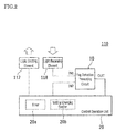
- FIG. 2 is a schematic block diagram of an electrical configuration of the laser range finder 110.
- FIG. 3 is a schematic diagram of the fog detection preventing circuit 10.
- the laser range finder 110 includes a laser light emitting section 111 and a laser light receiving section 115.
- the laser light emitting section 111 includes a laser light emitting element 112.
- the laser light receiving section 115 includes a light receiving lens 117 and a light receiving element 118.
- the laser range finder 110 is placed inside a housing 101 having an opening. The opening is covered with a lens cover 116 through which laser light can pass.
- pulsed laser light emitted from the laser light emitting element 112 in the laser light emitting section 111 passes through the lens cover 116 and reaches a human body or another like object that is present outside the housing 101. Part of the laser light reflected off such an object returns in the direction of the laser range finder 110 and passes through the lens cover 116 and then through the light receiving lens 117 before reaching the light receiving element 118.
- Distance data to the object such as a human body is acquired by precisely measuring a small amount of time from the emission of the pulsed laser light from the laser light emitting element 112 to the arrival of the reflected light to the light receiving element 118.
- Light-reception level data may additionally be acquired that represents intensity of the reflected light. If there is a plurality of objects in the direction in which the laser light is emitted, the distance data (and the light-reception level data) is acquired for each object.
- the laser light emitting element 112 in the laser light emitting section 111 may be, for example, a semiconductor laser diode (LD).
- the light receiving element 118 may be, for example, an avalanche photodiode (APD).
- Dedicated hardware circuitry may be desirably provided to control driving of the laser light emitting element 112, to measure the amount of time taken for the reflected light to return, and to acquire and record the light-reception level of the reflected light. This is however not the only possible configuration to achieve these purposes in this embodiment.
- a typical feature of laser range finders is their capability to precisely measure up to remarkably long distances, for example, no shorter than a few tens of meters, and in some cases, even much longer distances.
- a scanning mechanism 120 may be provided, as shown in FIG. 1 , mechanically connected to at least a part of the laser range finder 110, in order to change a measurement direction (angle) of the laser range finder 110.
- the scanning mechanism 120 if provided with a built-in electric motor and related components (not shown), becomes rotatable.
- either only the optical system in the laser range finder 110 or the entire laser range finder 110 may be configured to be rotatable. Other configurations are also possible. Rotating the scanning mechanism 120 at a certain rate in a predetermined direction enables the measurement direction of the laser range finder 110 to be changed in conjunction with this rotation.
- the laser range finder 110 includes the fog detection preventing circuit 10 and a control operation unit 20 in addition to the laser light emitting element 112 and the light receiving element 118 described above.
- the fog detection preventing circuit 10 has a first input terminal IN1 for receiving a light-reception output of the light receiving element 118, a second input terminal IN2 for control purposes, and an output terminal OUT for outputting a result of comparison.
- the control operation unit 20 has a control output terminal for the laser light emitting element 112, a control output terminal for the fog detection preventing circuit 10, and an input terminal for receiving an output from the output terminal OUT of the fog detection preventing circuit 10.
- the control operation unit 20 includes a timer 20a and a setting changing section 20b.
- the control operation unit 20 may double, for example, as an arithmetic and control unit controlling other functions of the laser range finder 110 and controlling the entire apparatus including the scanning mechanism 120.
- the fog detection preventing circuit 10 includes therein a comparator CMP having an output thereof connected to the output terminal OUT.
- One of input terminals of the comparator CMP is connected to the first input terminal IN1 to receive the light-reception output of the light receiving element 118.
- the other input terminal of the comparator CMP is connected to a contact between a resistor R2 (5.6 k ⁇ ) and a resistor R3 (220 ⁇ ) that are connected in series between a 3.3 V line and ground GND.
- the voltage that appears at this contact acts as a threshold for the comparator CMP.
- the contact is also connected to the second input terminal IN2 via a resistor R1 (1.2 k ⁇ ).
- This internal configuration of the fog detection preventing circuit 10 enables the comparator CMP to compare the light-reception output of the light receiving element 118 with the threshold. If the light-reception output is higher, the output terminal OUT outputs a HIGH level; otherwise, the output terminal OUT outputs a LOW level.
- the threshold inputted to the comparator CMP is variable with an input to the second input terminal IN2. If this input is the HIGH level, the threshold is about 600 mV; if the input is the LOW level, the threshold is about 100 mV.
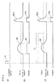
- FIG. 4 is a time chart for an exemplary situation where there exist fog at relatively close range and a human body at relatively far range.
- FIG. 4(a) represents a light-projection waveform.
- FIG. 4(b) represents the aforementioned threshold, a received light waveform, and the aforementioned comparator output when the fog detection preventing circuit 10 is out of operation.
- FIG. 4(c) represents the aforementioned threshold, a received light waveform, and the aforementioned comparator output when the fog detection preventing circuit 10 is in operation.
- pulsed laser light is emitted in accordance with a light-projection waveform P1 outputted from the control operation unit 20 to the laser light emitting element 112.
- the input from the control operation unit 20 to the second input terminal IN2 of the fog detection preventing circuit 10 is changed to the HIGH level throughout a predetermined period T1 starting at a time of rising of the light-projection waveform P1.
- the threshold inputted to the comparator CMP also rises to about 600 mV. Therefore, at the output of the comparator CMP, there appears on the time axis only the narrow pulse waveform PH1 corresponding to the human body at relatively far range, and no pulse waveform PF corresponding to the fog at relatively close range.
- the predetermined period T1 is determined so that the threshold inputted to the comparator CMP is increased until a time equivalent of approximately 4 meters (or approximately 3 to 5 meters) of distance elapses because fog, up to approximately 4 meters away, could produce relatively intense reflected light that may cause erroneous detection.
- the axis of projected light and the axis of received light do not overlap and are separated by a distance at close range where fog could be detected. Accordingly, the light-reception level when fog is detected is less than or equal to a relatively low value.
- the light-reception level can be further lowered by using a non-spherical surface lens as a light projecting lens and the light receiving lens 117.
- a human body has a higher reflection level than fog. The aforementioned simple configuration is thus capable of removing adverse effects of fog without sacrificing human body detecting capability.
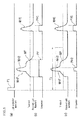
- FIG. 5 is a time chart for an exemplary situation where there exist fog and a human body at relatively close range and another human body at relatively far range.
- FIG. 5(a) represents a light-projection waveform.
- FIG. 5(b) represents the aforementioned threshold, a received light waveform, and the aforementioned comparator output when the fog detection preventing circuit 10 is out of operation.
- FIG. 5(c) represents the aforementioned threshold, a received light waveform, and the aforementioned comparator output when the fog detection preventing circuit 10 is in operation.
- pulsed laser light is emitted in accordance with a light-projection waveform P1 outputted from the control operation unit 20 to the laser light emitting element 112, similarly to the situation represented in FIG. 4(a) .
- the input from the control operation unit 20 to the second input terminal IN2 of the fog detection preventing circuit 10 is changed to the HIGH level throughout the predetermined period T1 starting at the time of rising of the light-projection waveform P1.
- the threshold inputted to the comparator CMP also rises to about 600 mV. Therefore, at the output of the comparator CMP, there appear on the time axis a pulse waveform PH2 corresponding to one of the human bodies at relatively close range and the narrow pulse waveform PH1 corresponding to the other human body at relatively far range. In other words, the human body is also accurately detectable at relatively close range because erroneous detection caused by the fog is prevented.
- the relatively simply configured fog detection preventing circuit 10 is additionally provided to the laser range finder 110.
- the fog detection preventing circuit 10 can prevent fog at relatively close range from being erroneously detected and appearing at the output of the comparator CMP. This in turn can obviate, for example, the need for a process that distinguishes between fog and a human body at relatively close range and hence simplify the process of identifying a human body over the entire range.
- the fog detection preventing circuit 10 additionally provided to a control operation circuit for the conventional TOF laser range finder, removes detection signals per se resulting from reflection off objects such as fog and a window face.
- the control operation circuit can be dedicated to processing of detection signals representing human bodies. This reduces workload in implementing a detection process and is expected to make some improvement in the detection performance of even a CPU with low processing power.
- the additional provision of the fog detection preventing circuit 10 can practically eliminate constraints that would occur in distinguishing between fog and a human body for detection and greatly improve close-range human body detecting capability in fog or a similarly poor environment.
- FIG. 6 is a schematic diagram of a fog detection preventing circuit 10A in accordance with a second embodiment of the present invention. Note that the second embodiment is the same as the first embodiment described in reference to FIG. 3 , except for the points detailed below. The same members are denoted by the same reference numerals. Description will focus on differences between the two embodiments.
- the fog detection preventing circuit 10A includes therein a comparator CMP having an output thereof connected to an output terminal OUT.
- One of input terminals of the comparator CMP is connected to a contact between a resistor R5 (50 ⁇ ) and a resistor R6 (50 ⁇ ) that are connected in series between ground GND and a first input terminal IN1 where a light-reception output of a light receiving element 118 is inputted.
- This contact is also connected to the drain of an FET whose source is grounded and whose gate is connected to a second input terminal IN2 via a resistor R4 (1 k ⁇ ).
- the other input terminal of the comparator CMP is connected to a contact between a resistor R7 (10.5 k ⁇ ) and a resistor R8 (330 ⁇ ) that are connected in series between a 3.3 V line and ground GND.
- the voltage that appears at this contact acts as a threshold for the comparator CMP.
- This internal configuration of the fog detection preventing circuit 10A fixes the threshold to be inputted to the comparator CMP at about 100 mV. Instead, an input gain (amplification factor) for the light-reception output from the light receiving element 118 to the first input terminal IN1 can be changed through an input to the second input terminal IN2.
- an input gain for the light-reception output from the light receiving element 118 to the first input terminal IN1 can be changed through an input to the second input terminal IN2.
- the input gain remains unchanged at approximately 1/1; when the input to the second input terminal IN2 is a HIGH level, the input gain falls to about 1/6.
- the configuration of the second embodiment described so far can achieve effects substantially similar to those achieved by the first embodiment by changing an input from a control operation unit 20 to the second input terminal IN2 of the fog detection preventing circuit 10A to a HIGH level throughout a predetermined period T1 starting at a time of rising of a light-projection waveform P1.
- the threshold for the comparator CMP or the input gain (amplification factor) for the light-reception output is discontinuously changed by changing the input from the control operation unit 20 to the second input terminal IN2 of the fog detection preventing circuit 10 or 10A to the HIGH level throughout the predetermined period T1 starting at the time of rising of the light-projection waveform P1.
- the threshold for the comparator CMP or the input gain (amplification factor) for the light-reception output may be changed stepwise during the predetermined period T1 starting at the time of rising of the light-projection waveform P1 by D/A converting the output of the control operation unit 20 and running a program in the control operation unit 20. Further alternatively, the threshold for the comparator CMP or the input gain (amplification factor) for the light-reception output may be changed continuously with time elapsed since the time of rising of the light-projection waveform P1 until the predetermined period T1 elapses.
Landscapes
- Engineering & Computer Science (AREA)
- Physics & Mathematics (AREA)
- Computer Networks & Wireless Communication (AREA)
- General Physics & Mathematics (AREA)
- Radar, Positioning & Navigation (AREA)
- Remote Sensing (AREA)
- Electromagnetism (AREA)
- Optical Radar Systems And Details Thereof (AREA)
Applications Claiming Priority (2)
| Application Number | Priority Date | Filing Date | Title |
|---|---|---|---|
| JP2015151888 | 2015-07-31 | ||
| JP2016125223A JP2017032547A (ja) | 2015-07-31 | 2016-06-24 | レーザ距離計用の誤検知抑制回路 |
Publications (1)
| Publication Number | Publication Date |
|---|---|
| EP3124996A1 true EP3124996A1 (de) | 2017-02-01 |
Family
ID=56615840
Family Applications (1)
| Application Number | Title | Priority Date | Filing Date |
|---|---|---|---|
| EP16182073.3A Withdrawn EP3124996A1 (de) | 2015-07-31 | 2016-07-29 | Fehldetektionrückhalteschaltung zur laserentfernungsmesser |
Country Status (2)
| Country | Link |
|---|---|
| US (1) | US10139477B2 (de) |
| EP (1) | EP3124996A1 (de) |
Cited By (5)
| Publication number | Priority date | Publication date | Assignee | Title |
|---|---|---|---|---|
| EP3671264A1 (de) * | 2018-12-21 | 2020-06-24 | Sick Ag | Sensor und verfahren zur erfassung eines objekts |
| EP3602111A4 (de) * | 2017-03-28 | 2020-12-09 | Luminar Technologies, Inc. | Zeitveränderliche verstärkung bei einem in einem lidar-system betriebenen optischen detektor |
| EP3584602A4 (de) * | 2017-02-15 | 2020-12-09 | Pioneer Corporation | Optische abtastvorrichtung und steuerungsverfahren |
| EP4283331A1 (de) * | 2022-05-24 | 2023-11-29 | Sick Ag | Optische erfassung und abstandsmessung |
| EP4143607A4 (de) * | 2020-04-28 | 2024-10-16 | Ouster, Inc. | Lidar-system mit nebelerkennung und adaptiver reaktion |
Families Citing this family (2)
| Publication number | Priority date | Publication date | Assignee | Title |
|---|---|---|---|---|
| US10267899B2 (en) * | 2017-03-28 | 2019-04-23 | Luminar Technologies, Inc. | Pulse timing based on angle of view |
| US11828882B2 (en) * | 2017-08-28 | 2023-11-28 | Sony Semiconductor Solutions Corporation | Distance measuring device and distance measuring method |
Citations (5)
| Publication number | Priority date | Publication date | Assignee | Title |
|---|---|---|---|---|
| US5627511A (en) * | 1994-08-30 | 1997-05-06 | Nippondenso Co., Ltd. | Distance measuring apparatus for automotive vehicles that compensates for the influence of particles floating in the air |
| US5739901A (en) * | 1995-05-12 | 1998-04-14 | Mitsubishi Denki Kabushiki Kaisha | Distance measuring apparatus and distance measuring method for a vehicle |
| US6819407B2 (en) * | 2002-02-08 | 2004-11-16 | Omron Corporation | Distance measuring apparatus |
| JP5092076B2 (ja) | 2007-10-26 | 2012-12-05 | オプテックス株式会社 | レーザエリアセンサ |
| JP5439684B2 (ja) | 2009-07-17 | 2014-03-12 | オプテックス株式会社 | レーザスキャンセンサ |
Family Cites Families (3)
| Publication number | Priority date | Publication date | Assignee | Title |
|---|---|---|---|---|
| JPS595981A (ja) | 1982-07-01 | 1984-01-12 | Mitsubishi Electric Corp | 測距装置 |
| JPS59142488A (ja) | 1983-02-02 | 1984-08-15 | Nissan Motor Co Ltd | 光レ−ダ装置 |
| EP0971242A1 (de) * | 1998-07-10 | 2000-01-12 | Cambridge Consultants Limited | Sensorsignalverarbeitung |
-
2016
- 2016-07-27 US US15/220,691 patent/US10139477B2/en active Active
- 2016-07-29 EP EP16182073.3A patent/EP3124996A1/de not_active Withdrawn
Patent Citations (5)
| Publication number | Priority date | Publication date | Assignee | Title |
|---|---|---|---|---|
| US5627511A (en) * | 1994-08-30 | 1997-05-06 | Nippondenso Co., Ltd. | Distance measuring apparatus for automotive vehicles that compensates for the influence of particles floating in the air |
| US5739901A (en) * | 1995-05-12 | 1998-04-14 | Mitsubishi Denki Kabushiki Kaisha | Distance measuring apparatus and distance measuring method for a vehicle |
| US6819407B2 (en) * | 2002-02-08 | 2004-11-16 | Omron Corporation | Distance measuring apparatus |
| JP5092076B2 (ja) | 2007-10-26 | 2012-12-05 | オプテックス株式会社 | レーザエリアセンサ |
| JP5439684B2 (ja) | 2009-07-17 | 2014-03-12 | オプテックス株式会社 | レーザスキャンセンサ |
Cited By (9)
| Publication number | Priority date | Publication date | Assignee | Title |
|---|---|---|---|---|
| EP3584602A4 (de) * | 2017-02-15 | 2020-12-09 | Pioneer Corporation | Optische abtastvorrichtung und steuerungsverfahren |
| EP3602111A4 (de) * | 2017-03-28 | 2020-12-09 | Luminar Technologies, Inc. | Zeitveränderliche verstärkung bei einem in einem lidar-system betriebenen optischen detektor |
| EP3671264A1 (de) * | 2018-12-21 | 2020-06-24 | Sick Ag | Sensor und verfahren zur erfassung eines objekts |
| CN111352122A (zh) * | 2018-12-21 | 2020-06-30 | 西克股份公司 | 用于检测对象的传感器和方法 |
| CN111352122B (zh) * | 2018-12-21 | 2023-01-03 | 西克股份公司 | 用于检测对象的传感器和方法 |
| US11592552B2 (en) | 2018-12-21 | 2023-02-28 | Sick Ag | Sensor and method for detecting an object |
| EP4143607A4 (de) * | 2020-04-28 | 2024-10-16 | Ouster, Inc. | Lidar-system mit nebelerkennung und adaptiver reaktion |
| US12270950B2 (en) | 2020-04-28 | 2025-04-08 | Ouster, Inc. | LIDAR system with fog detection and adaptive response |
| EP4283331A1 (de) * | 2022-05-24 | 2023-11-29 | Sick Ag | Optische erfassung und abstandsmessung |
Also Published As
| Publication number | Publication date |
|---|---|
| US20170031011A1 (en) | 2017-02-02 |
| US10139477B2 (en) | 2018-11-27 |
Similar Documents
| Publication | Publication Date | Title |
|---|---|---|
| US10139477B2 (en) | Erroneous detection restraining circuit for laser range finder | |
| CN112368597B (zh) | 光测距装置 | |
| US11961306B2 (en) | Object detection device | |
| JP5439684B2 (ja) | レーザスキャンセンサ | |
| US7760336B2 (en) | Laser area sensor | |
| US11933896B2 (en) | Optical distance measuring apparatus | |
| US10339405B2 (en) | Image recognition device and image recognition method | |
| JP5540217B2 (ja) | レーザースキャンセンサ | |
| CN110244316A (zh) | 接收光脉冲的接收器组件、LiDAR模组和接收光脉冲的方法 | |
| JP7069629B2 (ja) | 距離測定装置、移動体、距離測定方法およびプログラム | |
| JP6557923B2 (ja) | 車載レーダ装置及び領域検出方法 | |
| JP7375789B2 (ja) | 測距装置 | |
| US20230162395A1 (en) | Point-Cloud Processing | |
| JP6874592B2 (ja) | 時間測定装置、距離測定装置、移動体、時間測定方法、及び距離測定方法 | |
| US20230108583A1 (en) | Distance measurement device | |
| US20190178996A1 (en) | Distance measuring device | |
| WO2023181948A1 (ja) | ノイズ除去装置、物体検出装置およびノイズ除去方法 | |
| JP2017032547A (ja) | レーザ距離計用の誤検知抑制回路 | |
| JP2019028039A (ja) | 距離測定装置及び距離測定方法 | |
| KR20170105295A (ko) | 거리 측정 장치 | |
| US20220003853A1 (en) | Distance measuring device and malfunction determination method for distance measuring device | |
| JP7673764B2 (ja) | ノイズ除去装置、物体検出装置およびノイズ除去方法 | |
| WO2019188326A1 (ja) | センサ装置 | |
| US11308637B2 (en) | Distance detection method, distance detection system and computer program product | |
| CN115176175B (zh) | 物体检测装置 |
Legal Events
| Date | Code | Title | Description |
|---|---|---|---|
| PUAI | Public reference made under article 153(3) epc to a published international application that has entered the european phase |
Free format text: ORIGINAL CODE: 0009012 |
|
| AK | Designated contracting states |
Kind code of ref document: A1 Designated state(s): AL AT BE BG CH CY CZ DE DK EE ES FI FR GB GR HR HU IE IS IT LI LT LU LV MC MK MT NL NO PL PT RO RS SE SI SK SM TR |
|
| AX | Request for extension of the european patent |
Extension state: BA ME |
|
| RIN1 | Information on inventor provided before grant (corrected) |
Inventor name: IWASAWA, MASASHI |
|
| 17P | Request for examination filed |
Effective date: 20170728 |
|
| RBV | Designated contracting states (corrected) |
Designated state(s): AL AT BE BG CH CY CZ DE DK EE ES FI FR GB GR HR HU IE IS IT LI LT LU LV MC MK MT NL NO PL PT RO RS SE SI SK SM TR |
|
| 17Q | First examination report despatched |
Effective date: 20190617 |
|
| STAA | Information on the status of an ep patent application or granted ep patent |
Free format text: STATUS: THE APPLICATION HAS BEEN WITHDRAWN |
|
| 18W | Application withdrawn |
Effective date: 20191223 |