EP3125066A2 - Kochvorrichtung mit einer bediendrucktaste - Google Patents
Kochvorrichtung mit einer bediendrucktaste Download PDFInfo
- Publication number
- EP3125066A2 EP3125066A2 EP16177534.1A EP16177534A EP3125066A2 EP 3125066 A2 EP3125066 A2 EP 3125066A2 EP 16177534 A EP16177534 A EP 16177534A EP 3125066 A2 EP3125066 A2 EP 3125066A2
- Authority
- EP
- European Patent Office
- Prior art keywords
- tab
- pushbutton
- control
- inner body
- home appliance
- Prior art date
- Legal status (The legal status is an assumption and is not a legal conclusion. Google has not performed a legal analysis and makes no representation as to the accuracy of the status listed.)
- Withdrawn
Links
- 238000010411 cooking Methods 0.000 title claims description 6
- 239000000463 material Substances 0.000 claims description 5
- 238000002347 injection Methods 0.000 description 1
- 239000007924 injection Substances 0.000 description 1
- 238000000034 method Methods 0.000 description 1
Images



Classifications
-
- G—PHYSICS
- G05—CONTROLLING; REGULATING
- G05G—CONTROL DEVICES OR SYSTEMS INSOFAR AS CHARACTERISED BY MECHANICAL FEATURES ONLY
- G05G1/00—Controlling members, e.g. knobs or handles; Assemblies or arrangements thereof; Indicating position of controlling members
- G05G1/08—Controlling members for hand actuation by rotary movement, e.g. hand wheels
- G05G1/087—Controlling members for hand actuation by rotary movement, e.g. hand wheels retractable; Flush control knobs
Definitions
- the present invention relates to a home appliance having a rotary control pushbutton.
- Rotary control pushbuttons are placed into a casing embodied on a panel positioned on a cooking device.
- a holding section of the pushbutton is released out of the panel by a system embodied in the pushbutton, and when not in use, said holding section is retracted inside the casing, and thus, a flush surface is obtained on the panel.
- Said releasing and retracting of pushbuttons having unique start and stop positions are realized by means of a simple fingertip pressure exerted onto the outer flat surface of the pushbutton.
- the invention is a simplified retractable knob in which an actuating element can be displaced axially with respect to a bearing element with or counter to the force of a coiled spring.
- a latching element is integrated into the coil spring, which is guided in a guideway having at least a rest position and an actuating position of the actuating element.
- the object of the present invention is to reduce the number of sub-components in the rotary control pushbuttons used in home appliances and to facilitate production and to provide expedite assembly.
- the present invention comprises a tab which is one-piece with the inner body and positioned to an inner edge of an opening formed on the inner body, said tab providing adjustment of the start and stop positions of the pushbutton by moving axially in the channels provided on the guide element. Since the tab is one-piece with the inner body, the number of sub-components is reduced and rapid assembly is provided in rotary pushbuttons. Moreover, production is facilitated by reducing material variety and complexity of the pushbutton.
- the tab has an embodiment which can easily function inside indented channels.
- a neck section is provided on the tab in the region between the inner edge and the tab end section.
- the neck section width is smaller than the tab width.
- At least one of the corners provided on the tab is a rounded corner.
- the tab and the inner body are made of the same plastic material.
- the material variety and complexity during production are reduced, and production is facilitated.
- the present invention is a cooking device with a control element has a gas tap.
- the present invention relates to a home appliance (1) having rotary control pushbutton (2) where the number of sub-components is reduced and the assembly of the pushbutton is facilitated and the assembly duration is shortened and production is facilitated.
- the control pushbutton (2) is connected to a control element (50) and it can be used in all home appliances.
- a cooking device having a control element (50) and a tap functioning by means of gas is illustrated in Figure 1 .
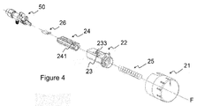
- the rotary control pushbutton (2) comprises a control sleeve (21) having a cylindrical structure, a helical spring (25) placed into the gap formed by the cylindrical periphery of the control sleeve (21), an inner body (22) which is similar to a rectangular prism, and a guide element (24) axially guided to the gap provided in the inner body (22).
- a control sleeve (21) having a cylindrical structure
- a helical spring (25) placed into the gap formed by the cylindrical periphery of the control sleeve (21)
- an inner body (22) which is similar to a rectangular prism
- a guide element (24) axially guided to the gap provided in the inner body (22).
- channels (241) on the guide element (24) are formed for providing movement of a tab (23) positioned on the inner body (22).
- connection element (26) in the control pushbutton (2), and said connection element (26) is connected to the shafts of the elements like switch, thermostat, gas tap or electrical stove regulator, and said connection element (26) prevents unintentional and uncontrolled removal of the pushbutton.
- the control pushbutton (2) switches to an operation position by exerting pressure with fingertip in the direction of the movement axis (F) through a push surface (211) provided on a control sleeve (21). Again in the same manner, the pushbutton switches to the stop position by exerting pressure in the direction of the center movement axis (F) through the same push surface (211) provided on said control sleeve (21). Thus, the releasing-retracting of the control pushbutton (2) is realized in the axial direction by means of the exerted pressure.
- the pushbutton can also be rotated around its own axis.
- the operation-stop positions of the pushbutton in other words, the axial releasing-retracting actions of the pushbutton are provided with the help of a tab (23) moving inside the channels (241) provided on the guide element (24).
- the tab (23) advances inside the channels (241) having an indented form, and it is fixed to a channel section which has a form suitable for locking, and it provides the pushbutton to stay in this position.
- the tab (23) is released from this mentioned position, and by means of the axial back movement inside the channels (241), the pushbutton returns to its initial position.
- the control pushbutton (2) comprises a control sleeve (21), a helical spring (25), an inner body (22), a guide element (24) and a connection element (26).
- a tap operating with gas and having a control element (50) controlled by means of the control pushbutton (2) can be seen.
- the shaft of the tap operating with gas engages to a connection channel (242) provided on the guide element (24) and illustrated in Figure 3 , and it is connected with respect to the center movement axis (F).
- the tab (23) moving in the channels (241) provided on the guide element (24) is positioned to an inner edge (222) provided in an opening (221) existing on the inner body (22).
- the inner body (22) and said tab (23) are manufactured in a one-piece manner from the same plastic material by means of injection method.
- the neck section (233) is positioned on the tab (23) in the region between the inner edge (222) and the tab end section (232).
- the tab (23) has a form which is similar to rectangular prism and "U"-like form is created in the regions where the neck section (233) is provided.
- the width (234) of said neck section is smaller than the tab width (231).
- at least one of the corners provided on the tab (23) has a rounded corner (235).
- the rounded corner (235) is provided by forming curve at the corners of the tab (23) by means of breaking chamfer.
Landscapes
- Physics & Mathematics (AREA)
- General Physics & Mathematics (AREA)
- Engineering & Computer Science (AREA)
- Automation & Control Theory (AREA)
- Cookers (AREA)
- Switches With Compound Operations (AREA)
- Push-Button Switches (AREA)
Applications Claiming Priority (1)
| Application Number | Priority Date | Filing Date | Title |
|---|---|---|---|
| TR201509506 | 2015-07-31 |
Publications (2)
| Publication Number | Publication Date |
|---|---|
| EP3125066A2 true EP3125066A2 (de) | 2017-02-01 |
| EP3125066A3 EP3125066A3 (de) | 2017-02-08 |
Family
ID=56296736
Family Applications (1)
| Application Number | Title | Priority Date | Filing Date |
|---|---|---|---|
| EP16177534.1A Withdrawn EP3125066A3 (de) | 2015-07-31 | 2016-07-01 | Kochvorrichtung mit einer bediendrucktaste |
Country Status (1)
| Country | Link |
|---|---|
| EP (1) | EP3125066A3 (de) |
Cited By (3)
| Publication number | Priority date | Publication date | Assignee | Title |
|---|---|---|---|---|
| JP2020521550A (ja) * | 2017-05-30 | 2020-07-27 | ウェスト ファーマ サービシーズ イスラエル リミテッド | 印刷回路基板の縦置き構造 |
| US11819666B2 (en) | 2017-05-30 | 2023-11-21 | West Pharma. Services IL, Ltd. | Modular drive train for wearable injector |
| US12357767B2 (en) | 2016-08-01 | 2025-07-15 | West Pharma. Services IL, Ltd. | Partial door closure prevention spring |
Citations (1)
| Publication number | Priority date | Publication date | Assignee | Title |
|---|---|---|---|---|
| US6410871B1 (en) | 1999-06-19 | 2002-06-25 | Mannesmann Vdo Ag | Retractable rotary knob for switch including latch mechanism |
Family Cites Families (6)
| Publication number | Priority date | Publication date | Assignee | Title |
|---|---|---|---|---|
| TR199600723A2 (xx) * | 1996-09-12 | 1998-04-21 | Ar�El�K A.�. | Ev aletlerinde kullan�lan kontrol d��mesi. |
| DE10306583A1 (de) * | 2003-02-17 | 2004-09-02 | BSH Bosch und Siemens Hausgeräte GmbH | Lagervorrichtung für einen versenkbaren Knebel |
| EP1526422B1 (de) * | 2003-10-22 | 2007-02-14 | Lisi Automotive Rapid | Versenkbare Drehgriffvorrichtung einer Schalt-oder Stelleinrichtung insbesondere eines Haushaltsgeräts |
| TR200502678U (tr) * | 2005-07-08 | 2005-09-21 | Ocak Kalip İmalat San.Ve Ti̇c.Ltd.Şti̇. | Pişirme ocaklarında kullanılan kumanda düğmesinde yenilik |
| WO2008039159A1 (en) * | 2006-09-27 | 2008-04-03 | Ocak Kalip Makina Imalat Sanayi Ve Ticaret Limited Sirketi | Reinforced locker in control knob mechanisms |
| PL3063599T3 (pl) * | 2013-11-01 | 2019-12-31 | Arçelik Anonim Sirketi | Urządzenie gospodarstwa domowego zawierające pokrętło |
-
2016
- 2016-07-01 EP EP16177534.1A patent/EP3125066A3/de not_active Withdrawn
Patent Citations (1)
| Publication number | Priority date | Publication date | Assignee | Title |
|---|---|---|---|---|
| US6410871B1 (en) | 1999-06-19 | 2002-06-25 | Mannesmann Vdo Ag | Retractable rotary knob for switch including latch mechanism |
Cited By (3)
| Publication number | Priority date | Publication date | Assignee | Title |
|---|---|---|---|---|
| US12357767B2 (en) | 2016-08-01 | 2025-07-15 | West Pharma. Services IL, Ltd. | Partial door closure prevention spring |
| JP2020521550A (ja) * | 2017-05-30 | 2020-07-27 | ウェスト ファーマ サービシーズ イスラエル リミテッド | 印刷回路基板の縦置き構造 |
| US11819666B2 (en) | 2017-05-30 | 2023-11-21 | West Pharma. Services IL, Ltd. | Modular drive train for wearable injector |
Also Published As
| Publication number | Publication date |
|---|---|
| EP3125066A3 (de) | 2017-02-08 |
Similar Documents
| Publication | Publication Date | Title |
|---|---|---|
| EP3125066A2 (de) | Kochvorrichtung mit einer bediendrucktaste | |
| JP5982023B2 (ja) | 回転/押しボタン制御装置 | |
| AU2017298342B2 (en) | Medicament container holder for a medicament delivery device and method of assemblying a medicament delivery device | |
| EP2485111B1 (de) | Verbesserte zurücknehmbare Bedienung für Hausgerät | |
| CN109475701B (zh) | 用于药剂输送装置的药剂容器组件 | |
| US6972387B2 (en) | Padlockable push-button | |
| EP3462092A1 (de) | Kochvorrichtung mit bedienknopf | |
| EP3234974B1 (de) | Bedienvorrichtung für ein fahrzeug, insbesondere einen personenkraftwagen | |
| DE102006036636A1 (de) | Rasteinrichtung für ein Bedienelement in einem Kraftfahrzeug | |
| DE202016104274U1 (de) | Thermische Schalteinrichtung | |
| EP2735795B1 (de) | Gashahn für eine Kocheinrichtung | |
| EP3348716A1 (de) | Tragevorrichtung für einen duschkopf | |
| EP2469551B1 (de) | Kochvorrichtung mit einem versenkbaren Drehknebel | |
| EP3117850A1 (de) | Applikator mit kolben mit durch eine widerstandsstruktur begrenzter reichweite | |
| EP3323135B1 (de) | Hebelbetätigung für die steuerung elektrischer geräte | |
| KR101222707B1 (ko) | 가이드 와이어 방향 전환용 카테터 및 이를 이용한 가이드 와이어 방향 전환방법 | |
| EP3007193B1 (de) | Abzapfwechsler für ölgefüllte, elektrische transformatoren | |
| CN103322279A (zh) | 操纵设备 | |
| EP3707734B1 (de) | Elektromagnet und schaltbedienelement mit einem solchen elektromagneten | |
| EP3282194B1 (de) | Mit zahnradgetriebe ausgestatteter steuerknopf zur steuerung des leistungspegels eines brenners in einer gaskochstelle | |
| EP2597376B1 (de) | Kochvorrichtung mit Gashahnschaft | |
| CN112471906B (zh) | 烹饪装置及其盖体组件 | |
| KR0122763Y1 (ko) | 전자렌지의 조절노브 결합구조 | |
| WO2013120634A1 (de) | Elektrischer drucktaster mit einem dichtbalg und einer den dichtbalg beaufschlagenden feder sowie verfahren zu dessen montage | |
| EP3249298A1 (de) | Kochvorrichtung mit gashahn |
Legal Events
| Date | Code | Title | Description |
|---|---|---|---|
| PUAI | Public reference made under article 153(3) epc to a published international application that has entered the european phase |
Free format text: ORIGINAL CODE: 0009012 |
|
| PUAL | Search report despatched |
Free format text: ORIGINAL CODE: 0009013 |
|
| AK | Designated contracting states |
Kind code of ref document: A2 Designated state(s): AL AT BE BG CH CY CZ DE DK EE ES FI FR GB GR HR HU IE IS IT LI LT LU LV MC MK MT NL NO PL PT RO RS SE SI SK SM TR |
|
| AX | Request for extension of the european patent |
Extension state: BA ME |
|
| AK | Designated contracting states |
Kind code of ref document: A3 Designated state(s): AL AT BE BG CH CY CZ DE DK EE ES FI FR GB GR HR HU IE IS IT LI LT LU LV MC MK MT NL NO PL PT RO RS SE SI SK SM TR |
|
| AX | Request for extension of the european patent |
Extension state: BA ME |
|
| RIC1 | Information provided on ipc code assigned before grant |
Ipc: G05G 1/08 20060101AFI20170102BHEP |
|
| STAA | Information on the status of an ep patent application or granted ep patent |
Free format text: STATUS: THE APPLICATION IS DEEMED TO BE WITHDRAWN |
|
| 18D | Application deemed to be withdrawn |
Effective date: 20170809 |