EP3125375A1 - Verbesserte vorrichtung und verbessertes verfahren zum anschliessen eines ersten bündels von leitern, die nach zufallsmuster an ein bündel von identifizierten leitern angeschlossen sind, insbesondere für den anschluss eines kabelstrangs - Google Patents
Verbesserte vorrichtung und verbessertes verfahren zum anschliessen eines ersten bündels von leitern, die nach zufallsmuster an ein bündel von identifizierten leitern angeschlossen sind, insbesondere für den anschluss eines kabelstrangs Download PDFInfo
- Publication number
- EP3125375A1 EP3125375A1 EP16181284.7A EP16181284A EP3125375A1 EP 3125375 A1 EP3125375 A1 EP 3125375A1 EP 16181284 A EP16181284 A EP 16181284A EP 3125375 A1 EP3125375 A1 EP 3125375A1
- Authority
- EP
- European Patent Office
- Prior art keywords
- conductors
- signals
- bundle
- identified
- housing
- Prior art date
- Legal status (The legal status is an assumption and is not a legal conclusion. Google has not performed a legal analysis and makes no representation as to the accuracy of the status listed.)
- Granted
Links
Images
Classifications
-
- H—ELECTRICITY
- H01—ELECTRIC ELEMENTS
- H01R—ELECTRICALLY-CONDUCTIVE CONNECTIONS; STRUCTURAL ASSOCIATIONS OF A PLURALITY OF MUTUALLY-INSULATED ELECTRICAL CONNECTING ELEMENTS; COUPLING DEVICES; CURRENT COLLECTORS
- H01R29/00—Coupling parts for selective co-operation with a counterpart in different ways to establish different circuits, e.g. for voltage selection, for series-parallel selection, programmable connectors
-
- G—PHYSICS
- G01—MEASURING; TESTING
- G01R—MEASURING ELECTRIC VARIABLES; MEASURING MAGNETIC VARIABLES
- G01R31/00—Arrangements for testing electric properties; Arrangements for locating electric faults; Arrangements for electrical testing characterised by what is being tested not provided for elsewhere
- G01R31/005—Testing of electric installations on transport means
-
- G—PHYSICS
- G01—MEASURING; TESTING
- G01R—MEASURING ELECTRIC VARIABLES; MEASURING MAGNETIC VARIABLES
- G01R31/00—Arrangements for testing electric properties; Arrangements for locating electric faults; Arrangements for electrical testing characterised by what is being tested not provided for elsewhere
- G01R31/50—Testing of electric apparatus, lines, cables or components for short-circuits, continuity, leakage current or incorrect line connections
- G01R31/58—Testing of lines, cables or conductors
- G01R31/60—Identification of wires in a multicore cable
-
- H—ELECTRICITY
- H01—ELECTRIC ELEMENTS
- H01R—ELECTRICALLY-CONDUCTIVE CONNECTIONS; STRUCTURAL ASSOCIATIONS OF A PLURALITY OF MUTUALLY-INSULATED ELECTRICAL CONNECTING ELEMENTS; COUPLING DEVICES; CURRENT COLLECTORS
- H01R2201/00—Connectors or connections adapted for particular applications
- H01R2201/26—Connectors or connections adapted for particular applications for vehicles
Definitions
- the present invention generally relates to connecting a first bundle of conductors to a second bundle of conductors.
- the invention relates to the connection of a hitch beam to a harness of conductors for rear lights of a motor vehicle.
- Installers must first consult a specific technical document for each vehicle to identify the conductors of the tail light beam, which causes a significant loss of time.
- junction box intended to be connected, on the one hand, as input, to the tail light beam and, on the other hand, at the output, to the driving beam and comprising addressable inputs and addressing means for selecting commands to identify the driver of the tow beam corresponding to the selected command, after acknowledgment thereof, and to address the inputs after identification of the conductors.
- the junction box is configured to match all the drivers of the hitch beam with the taillight conductors.
- junction box is advantageous in many respects, it has been found that developments in embedded technology in motor vehicles tend increasingly to diversify the signals to the rear lights.
- the signals corresponding to a lighting function may have characteristics that vary. For example, it may happen that motor vehicle manufacturers modify the frequency of a signal related to the execution of a function.
- the object of the invention is therefore to overcome these various disadvantages.
- Another object of the invention is to propose a device for connecting conductor bundles capable of facilitating the recognition of conductors and, consequently, of making it easier to relate a towing beam to a beam of lights. rear of a motor vehicle.
- the invention thus has, according to a first aspect, a device for connecting a first bundle of conductors connected randomly to a second bundle of identified conductors, comprising a housing that is connected between the first and the second bundle.
- This device comprises means for identifying the conductors of the first beam from characteristics of the signals they convey and means for directing the identified conductors to corresponding conductors of the second beam.
- Such a device is thus able to recognize the drivers of the first beam, in this case the drivers of a vehicle rear light beam and this, by simple comparison with known signal characteristics and stored in memory.
- the means for identifying the conductors comprise means for storing the signals and means for comparing the stored signals with identification signals stored in memory and corresponding to predetermined functions.
- the comparison means are adapted to compare the measured signals with the identification signals so as to identify the measured signals with a margin of tolerance.
- the device comprises a microcontroller comprising said comparison means and said memory and a power stage receiving control commands issued by the comparison means for conveying the identified signals to the corresponding signals of the second beam.
- the housing comprises addressable inputs connected to the first beam and addressable address addressing means for directing the identified beams to the corresponding conductors of the second beam.
- the addressing means comprise a human-machine interface for selecting commands and adapted to assign inputs to the outputs of the box.
- the device comprises means for periodically identifying the conductors of the first beam from characteristics of the signals they convey.
- the invention also relates, according to a second aspect, to a method of connecting a first bundle of conductors connected randomly to a second bundle of identified conductors.
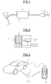
- connection device 1 On the figure 1 the general architecture of a connection device for conductor bundles designated by the general reference numeral 1 is shown.
- This device is intended to allow the connection of a first bundle 2 of conductors to a second bundle 3 of conductors.
- these are, respectively, a rear light beam of a motor vehicle and a coupling beam, that is to say a bundle of conductors intended to be connected to a motor vehicle. coupling.
- the device 1 constitutes a casing which is connected between the first beam 2 and the second conductor beam 3 and is intended to allow the assignment of the conductors of the first beam 2, which are connected randomly, to the conductors of the other beam, previously identified, to match them without previously identifying, manually, the beams of the first bundle of conductors 2.
- the device 1 essentially comprises a connection box 4 comprising a set of inputs 5 on which are connected the conductors of the first beam 2 and an output 6 equipped with a plug 7 to be connected to a corresponding socket 8 of the beam of coupling 3.
- connection box 4 comprises, internally, an input and control stage and a power stage 11 receiving control signals delivered by the input and control stage 10.
- a general supply stage 12 supplies the power stage 11 as well as the input and control stage 10 via a secondary supply stage 13.
- the input and control stage 10 comprises a microcontroller 14 ensuring the actual detection of the functions of the drivers of the tail light beam associated with a memory 15.
- the microcontroller 14 receives, at input E, the signals conveyed by each of the conductors.
- the microcontroller 14 stores the signals conveyed and compares these signals with corresponding signals stored in memory 15. For example, the characteristics of the signals received as input are compared. with the corresponding characteristics of the stored signals whose function is known.
- the signals from the tail light beam received at the input may be necessary to identify the signals from the tail light beam received at the input that correspond to a night light function, a left flashing function, a right flashing function, an anti-fog function, etc.
- the microcontroller 10 transmits control signals to the power stage 11 which, for example, comprises configurable circuit elements, provided with relays switching the power to the hitch, so as to transmit the identified signals to the tow beam conductors that provide the identified function.
- the power stage 11 which, for example, comprises configurable circuit elements, provided with relays switching the power to the hitch, so as to transmit the identified signals to the tow beam conductors that provide the identified function.
- the box is thus able to identify the signals it receives at the input in order to be able to route them to the corresponding outputs. It is also capable of separating different signals conveyed on the same conductor and corresponding to different functions.
- the outputs can thus be activated selectively depending on the input conductors.
- some motor vehicles have one or more bulbs that can have multiple functions. It can be a night-light function, a stop function and an anti-fog function. These functions are performed from three different signal levels.
- the detection of the signals conveyed and their comparison with corresponding signals stored in memory thus makes it possible to identify the function, whether it is combined with other functions within the same bulb or is deported to another light bulb. .
- connection of a first bundle of conductors randomly connected, in this case a rear light beam of a motor vehicle, to a second bundle of identified conductors, here a coupling beam consists in identifying the conductors of the first beam from characteristics of the signals they convey, by storing and comparing the signals received at the input of the box with stored signals.
- the signals are conveyed in a carrier simultaneously with signals serving for the transmission of information of various kinds, concerning for example the pressure of the tires, the signals then being demodulated to be compared with signals stored in memory.
- the signals are recognized by positioning the housing 4 in an identification mode. It may, for example, be to position a specific input of the housing to a predetermined voltage level, for example equal to 12 volts, for a predetermined time.
- the inputs are programmed to match the outputs of the box.
- Such addressing is a procedure within the reach of a person skilled in the art. It will not be described in detail later.
- the housing can thus include input addressing means for communicating each input on which an identified signal flows with a corresponding output of the housing 4.
- a configuration box 16 which is connected to the box 4 and includes functions enabling the activation or deactivation of functions of the vehicle.
- the signal thus produced is detected and identified by the housing 4 which, in response, proceeds to address the corresponding input to route the identified signal to the corresponding output of the housing 4 and, consequently, the corresponding driver of the coupling beam 3.
Landscapes
- Physics & Mathematics (AREA)
- General Physics & Mathematics (AREA)
- Insulated Conductors (AREA)
Applications Claiming Priority (1)
| Application Number | Priority Date | Filing Date | Title |
|---|---|---|---|
| FR1557143A FR3039716B1 (fr) | 2015-07-27 | 2015-07-27 | Dispositif et procede ameliores de raccordement d'un premier faisceau de conducteurs branches aleatoirement a un faisceau de conducteurs identifies |
Publications (2)
| Publication Number | Publication Date |
|---|---|
| EP3125375A1 true EP3125375A1 (de) | 2017-02-01 |
| EP3125375B1 EP3125375B1 (de) | 2021-08-11 |
Family
ID=54478795
Family Applications (1)
| Application Number | Title | Priority Date | Filing Date |
|---|---|---|---|
| EP16181284.7A Active EP3125375B1 (de) | 2015-07-27 | 2016-07-26 | Verbesserte vorrichtung zum anschliessen eines ersten bündels von leitern, die nach zufallsmuster an ein bündel von identifizierten leitern angeschlossen sind, insbesondere für den anschluss eines kabelstrangs, und ihre verwendung |
Country Status (2)
| Country | Link |
|---|---|
| EP (1) | EP3125375B1 (de) |
| FR (1) | FR3039716B1 (de) |
Citations (4)
| Publication number | Priority date | Publication date | Assignee | Title |
|---|---|---|---|---|
| WO2000060475A1 (en) * | 1999-04-06 | 2000-10-12 | Cablesoft, Inc. | A system for monitoring connection pattern of data ports |
| EP1648054A2 (de) | 2004-10-15 | 2006-04-19 | Construction Electromecaniques Thome | Vorrichtung und Verfahren zur Verbindung eines willkürlich verzweigten Kabelbaums an einen Kabelbaum mit bestimmten Kabeln, insbesondere zur Verbindung eines Anhängerkupplungskabels |
| EP2034423A2 (de) * | 2007-09-04 | 2009-03-11 | Apple Inc. | Intelligente Kabel |
| EP2590274A2 (de) * | 2011-11-07 | 2013-05-08 | Apple Inc. | Techniken zur Konfiguration von Kontakten eines Steckers |
Family Cites Families (1)
| Publication number | Priority date | Publication date | Assignee | Title |
|---|---|---|---|---|
| US3902026A (en) * | 1974-01-18 | 1975-08-26 | Electronic Control Systems Inc | Method and apparatus for identifying wires |
-
2015
- 2015-07-27 FR FR1557143A patent/FR3039716B1/fr not_active Expired - Fee Related
-
2016
- 2016-07-26 EP EP16181284.7A patent/EP3125375B1/de active Active
Patent Citations (4)
| Publication number | Priority date | Publication date | Assignee | Title |
|---|---|---|---|---|
| WO2000060475A1 (en) * | 1999-04-06 | 2000-10-12 | Cablesoft, Inc. | A system for monitoring connection pattern of data ports |
| EP1648054A2 (de) | 2004-10-15 | 2006-04-19 | Construction Electromecaniques Thome | Vorrichtung und Verfahren zur Verbindung eines willkürlich verzweigten Kabelbaums an einen Kabelbaum mit bestimmten Kabeln, insbesondere zur Verbindung eines Anhängerkupplungskabels |
| EP2034423A2 (de) * | 2007-09-04 | 2009-03-11 | Apple Inc. | Intelligente Kabel |
| EP2590274A2 (de) * | 2011-11-07 | 2013-05-08 | Apple Inc. | Techniken zur Konfiguration von Kontakten eines Steckers |
Also Published As
| Publication number | Publication date |
|---|---|
| FR3039716A1 (fr) | 2017-02-03 |
| EP3125375B1 (de) | 2021-08-11 |
| FR3039716B1 (fr) | 2017-08-25 |
Similar Documents
| Publication | Publication Date | Title |
|---|---|---|
| US10005384B2 (en) | Anti-dazzle headlamp | |
| CN107199943B (zh) | 用于机动车辆的智能灯组件和智能照明系统 | |
| US20170190336A1 (en) | Automated Vehicle Operation Based On Gesture To Pedestrian | |
| EP1298009B1 (de) | Beleuchtungs- oder Signalierungscheinwerfer und Verfahren mit zumindest einem Scheinwerfer | |
| US20130054087A1 (en) | Method for controlling a light emission of a headlight of a vehicle | |
| CN109899760B (zh) | 车灯装置 | |
| EP3844031B1 (de) | Zubehörsteuerung mit einem fahrzeugkommunikationsbus | |
| EP3700778B1 (de) | Scheinwerfereinheit mit autodimmfunktion | |
| CN115140074A (zh) | 用于操作驾驶员辅助功能的方法 | |
| US8981647B2 (en) | Lighting system | |
| US9902309B2 (en) | Vehicle and method for illuminating a region rearward of a vehicle | |
| EP3125375B1 (de) | Verbesserte vorrichtung zum anschliessen eines ersten bündels von leitern, die nach zufallsmuster an ein bündel von identifizierten leitern angeschlossen sind, insbesondere für den anschluss eines kabelstrangs, und ihre verwendung | |
| EP2725876A1 (de) | Elektrische Anschlussvorrichtung eines Scheinwerfers | |
| EP3386799B1 (de) | Homogenes rücklichtsystem für ein kraftfahrzeug | |
| EP3899779A1 (de) | Verfahren zur gewinnung eines bildes eines zu klassifizierenden objektes und zugehöriges system | |
| CN213586382U (zh) | 多光源前照灯的控制系统 | |
| EP1648054B1 (de) | Vorrichtung und Verfahren zur Verbindung eines willkürlich verzweigten Kabelbaums an einen Kabelbaum mit bestimmten Kabeln, insbesondere zur Verbindung eines Anhängerkupplungskabels | |
| EP3398813B1 (de) | Beleuchtungsmodul für ein fahrzeug | |
| FR2921601A3 (fr) | Dispositif de securite aux intersections pour vehicule automobile | |
| FR3096756A1 (fr) | Procédé de commande d’un système de signalisation d’un véhicule automobile | |
| EP4668679A1 (de) | System und verfahren zur steuerung von fahrzeuglampen | |
| US12441234B2 (en) | Method, control arrangement, and control device for controlling a rear lamp in a vehicle | |
| CN111835946B (zh) | 视觉系统和对象检测方法 | |
| EP2461252A1 (de) | Automatisches Erkennungsverfahren eines Lichtsteuerbusses | |
| CN109484282A (zh) | 一种汽车远近光灯智能切换装置 |
Legal Events
| Date | Code | Title | Description |
|---|---|---|---|
| PUAI | Public reference made under article 153(3) epc to a published international application that has entered the european phase |
Free format text: ORIGINAL CODE: 0009012 |
|
| STAA | Information on the status of an ep patent application or granted ep patent |
Free format text: STATUS: THE APPLICATION HAS BEEN PUBLISHED |
|
| AK | Designated contracting states |
Kind code of ref document: A1 Designated state(s): AL AT BE BG CH CY CZ DE DK EE ES FI FR GB GR HR HU IE IS IT LI LT LU LV MC MK MT NL NO PL PT RO RS SE SI SK SM TR |
|
| AX | Request for extension of the european patent |
Extension state: BA ME |
|
| STAA | Information on the status of an ep patent application or granted ep patent |
Free format text: STATUS: REQUEST FOR EXAMINATION WAS MADE |
|
| 17P | Request for examination filed |
Effective date: 20170713 |
|
| STAA | Information on the status of an ep patent application or granted ep patent |
Free format text: STATUS: EXAMINATION IS IN PROGRESS |
|
| 17Q | First examination report despatched |
Effective date: 20180529 |
|
| REG | Reference to a national code |
Ref country code: DE Ref legal event code: R079 Ref document number: 602016061899 Country of ref document: DE Free format text: PREVIOUS MAIN CLASS: H01R0029000000 Ipc: G01R0031000000 |
|
| GRAP | Despatch of communication of intention to grant a patent |
Free format text: ORIGINAL CODE: EPIDOSNIGR1 |
|
| STAA | Information on the status of an ep patent application or granted ep patent |
Free format text: STATUS: GRANT OF PATENT IS INTENDED |
|
| RIC1 | Information provided on ipc code assigned before grant |
Ipc: G01R 31/00 20060101AFI20200831BHEP Ipc: H01R 29/00 20060101ALI20200831BHEP Ipc: G01R 31/60 20200101ALI20200831BHEP |
|
| INTG | Intention to grant announced |
Effective date: 20200918 |
|
| 19U | Interruption of proceedings before grant |
Effective date: 20200203 |
|
| 19W | Proceedings resumed before grant after interruption of proceedings |
Effective date: 20210401 |
|
| RAP3 | Party data changed (applicant data changed or rights of an application transferred) |
Owner name: SEF POWER |
|
| GRAJ | Information related to disapproval of communication of intention to grant by the applicant or resumption of examination proceedings by the epo deleted |
Free format text: ORIGINAL CODE: EPIDOSDIGR1 |
|
| GRAP | Despatch of communication of intention to grant a patent |
Free format text: ORIGINAL CODE: EPIDOSNIGR1 |
|
| GRAS | Grant fee paid |
Free format text: ORIGINAL CODE: EPIDOSNIGR3 |
|
| GRAA | (expected) grant |
Free format text: ORIGINAL CODE: 0009210 |
|
| STAA | Information on the status of an ep patent application or granted ep patent |
Free format text: STATUS: THE PATENT HAS BEEN GRANTED |
|
| INTG | Intention to grant announced |
Effective date: 20210618 |
|
| INTG | Intention to grant announced |
Effective date: 20210618 |
|
| AK | Designated contracting states |
Kind code of ref document: B1 Designated state(s): AL AT BE BG CH CY CZ DE DK EE ES FI FR GB GR HR HU IE IS IT LI LT LU LV MC MK MT NL NO PL PT RO RS SE SI SK SM TR |
|
| REG | Reference to a national code |
Ref country code: CH Ref legal event code: EP |
|
| REG | Reference to a national code |
Ref country code: DE Ref legal event code: R096 Ref document number: 602016061899 Country of ref document: DE |
|
| REG | Reference to a national code |
Ref country code: IE Ref legal event code: FG4D Free format text: LANGUAGE OF EP DOCUMENT: FRENCH Ref country code: AT Ref legal event code: REF Ref document number: 1419915 Country of ref document: AT Kind code of ref document: T Effective date: 20210915 |
|
| REG | Reference to a national code |
Ref country code: LT Ref legal event code: MG9D |
|
| REG | Reference to a national code |
Ref country code: NL Ref legal event code: MP Effective date: 20210811 |
|
| REG | Reference to a national code |
Ref country code: AT Ref legal event code: MK05 Ref document number: 1419915 Country of ref document: AT Kind code of ref document: T Effective date: 20210811 |
|
| PG25 | Lapsed in a contracting state [announced via postgrant information from national office to epo] |
Ref country code: LT Free format text: LAPSE BECAUSE OF FAILURE TO SUBMIT A TRANSLATION OF THE DESCRIPTION OR TO PAY THE FEE WITHIN THE PRESCRIBED TIME-LIMIT Effective date: 20210811 Ref country code: BG Free format text: LAPSE BECAUSE OF FAILURE TO SUBMIT A TRANSLATION OF THE DESCRIPTION OR TO PAY THE FEE WITHIN THE PRESCRIBED TIME-LIMIT Effective date: 20211111 Ref country code: AT Free format text: LAPSE BECAUSE OF FAILURE TO SUBMIT A TRANSLATION OF THE DESCRIPTION OR TO PAY THE FEE WITHIN THE PRESCRIBED TIME-LIMIT Effective date: 20210811 Ref country code: ES Free format text: LAPSE BECAUSE OF FAILURE TO SUBMIT A TRANSLATION OF THE DESCRIPTION OR TO PAY THE FEE WITHIN THE PRESCRIBED TIME-LIMIT Effective date: 20210811 Ref country code: FI Free format text: LAPSE BECAUSE OF FAILURE TO SUBMIT A TRANSLATION OF THE DESCRIPTION OR TO PAY THE FEE WITHIN THE PRESCRIBED TIME-LIMIT Effective date: 20210811 Ref country code: PT Free format text: LAPSE BECAUSE OF FAILURE TO SUBMIT A TRANSLATION OF THE DESCRIPTION OR TO PAY THE FEE WITHIN THE PRESCRIBED TIME-LIMIT Effective date: 20211213 Ref country code: NO Free format text: LAPSE BECAUSE OF FAILURE TO SUBMIT A TRANSLATION OF THE DESCRIPTION OR TO PAY THE FEE WITHIN THE PRESCRIBED TIME-LIMIT Effective date: 20211111 Ref country code: SE Free format text: LAPSE BECAUSE OF FAILURE TO SUBMIT A TRANSLATION OF THE DESCRIPTION OR TO PAY THE FEE WITHIN THE PRESCRIBED TIME-LIMIT Effective date: 20210811 Ref country code: RS Free format text: LAPSE BECAUSE OF FAILURE TO SUBMIT A TRANSLATION OF THE DESCRIPTION OR TO PAY THE FEE WITHIN THE PRESCRIBED TIME-LIMIT Effective date: 20210811 Ref country code: HR Free format text: LAPSE BECAUSE OF FAILURE TO SUBMIT A TRANSLATION OF THE DESCRIPTION OR TO PAY THE FEE WITHIN THE PRESCRIBED TIME-LIMIT Effective date: 20210811 |
|
| PG25 | Lapsed in a contracting state [announced via postgrant information from national office to epo] |
Ref country code: PL Free format text: LAPSE BECAUSE OF FAILURE TO SUBMIT A TRANSLATION OF THE DESCRIPTION OR TO PAY THE FEE WITHIN THE PRESCRIBED TIME-LIMIT Effective date: 20210811 Ref country code: LV Free format text: LAPSE BECAUSE OF FAILURE TO SUBMIT A TRANSLATION OF THE DESCRIPTION OR TO PAY THE FEE WITHIN THE PRESCRIBED TIME-LIMIT Effective date: 20210811 Ref country code: GR Free format text: LAPSE BECAUSE OF FAILURE TO SUBMIT A TRANSLATION OF THE DESCRIPTION OR TO PAY THE FEE WITHIN THE PRESCRIBED TIME-LIMIT Effective date: 20211112 |
|
| PG25 | Lapsed in a contracting state [announced via postgrant information from national office to epo] |
Ref country code: NL Free format text: LAPSE BECAUSE OF FAILURE TO SUBMIT A TRANSLATION OF THE DESCRIPTION OR TO PAY THE FEE WITHIN THE PRESCRIBED TIME-LIMIT Effective date: 20210811 |
|
| PG25 | Lapsed in a contracting state [announced via postgrant information from national office to epo] |
Ref country code: DK Free format text: LAPSE BECAUSE OF FAILURE TO SUBMIT A TRANSLATION OF THE DESCRIPTION OR TO PAY THE FEE WITHIN THE PRESCRIBED TIME-LIMIT Effective date: 20210811 |
|
| REG | Reference to a national code |
Ref country code: DE Ref legal event code: R097 Ref document number: 602016061899 Country of ref document: DE |
|
| PG25 | Lapsed in a contracting state [announced via postgrant information from national office to epo] |
Ref country code: SM Free format text: LAPSE BECAUSE OF FAILURE TO SUBMIT A TRANSLATION OF THE DESCRIPTION OR TO PAY THE FEE WITHIN THE PRESCRIBED TIME-LIMIT Effective date: 20210811 Ref country code: SK Free format text: LAPSE BECAUSE OF FAILURE TO SUBMIT A TRANSLATION OF THE DESCRIPTION OR TO PAY THE FEE WITHIN THE PRESCRIBED TIME-LIMIT Effective date: 20210811 Ref country code: RO Free format text: LAPSE BECAUSE OF FAILURE TO SUBMIT A TRANSLATION OF THE DESCRIPTION OR TO PAY THE FEE WITHIN THE PRESCRIBED TIME-LIMIT Effective date: 20210811 Ref country code: EE Free format text: LAPSE BECAUSE OF FAILURE TO SUBMIT A TRANSLATION OF THE DESCRIPTION OR TO PAY THE FEE WITHIN THE PRESCRIBED TIME-LIMIT Effective date: 20210811 Ref country code: CZ Free format text: LAPSE BECAUSE OF FAILURE TO SUBMIT A TRANSLATION OF THE DESCRIPTION OR TO PAY THE FEE WITHIN THE PRESCRIBED TIME-LIMIT Effective date: 20210811 Ref country code: AL Free format text: LAPSE BECAUSE OF FAILURE TO SUBMIT A TRANSLATION OF THE DESCRIPTION OR TO PAY THE FEE WITHIN THE PRESCRIBED TIME-LIMIT Effective date: 20210811 |
|
| PLBE | No opposition filed within time limit |
Free format text: ORIGINAL CODE: 0009261 |
|
| STAA | Information on the status of an ep patent application or granted ep patent |
Free format text: STATUS: NO OPPOSITION FILED WITHIN TIME LIMIT |
|
| 26N | No opposition filed |
Effective date: 20220512 |
|
| PG25 | Lapsed in a contracting state [announced via postgrant information from national office to epo] |
Ref country code: IT Free format text: LAPSE BECAUSE OF FAILURE TO SUBMIT A TRANSLATION OF THE DESCRIPTION OR TO PAY THE FEE WITHIN THE PRESCRIBED TIME-LIMIT Effective date: 20210811 |
|
| PG25 | Lapsed in a contracting state [announced via postgrant information from national office to epo] |
Ref country code: SI Free format text: LAPSE BECAUSE OF FAILURE TO SUBMIT A TRANSLATION OF THE DESCRIPTION OR TO PAY THE FEE WITHIN THE PRESCRIBED TIME-LIMIT Effective date: 20210811 |
|
| REG | Reference to a national code |
Ref country code: DE Ref legal event code: R119 Ref document number: 602016061899 Country of ref document: DE |
|
| PG25 | Lapsed in a contracting state [announced via postgrant information from national office to epo] |
Ref country code: MC Free format text: LAPSE BECAUSE OF FAILURE TO SUBMIT A TRANSLATION OF THE DESCRIPTION OR TO PAY THE FEE WITHIN THE PRESCRIBED TIME-LIMIT Effective date: 20210811 |
|
| REG | Reference to a national code |
Ref country code: CH Ref legal event code: PL |
|
| GBPC | Gb: european patent ceased through non-payment of renewal fee |
Effective date: 20220726 |
|
| REG | Reference to a national code |
Ref country code: BE Ref legal event code: MM Effective date: 20220731 |
|
| PG25 | Lapsed in a contracting state [announced via postgrant information from national office to epo] |
Ref country code: LU Free format text: LAPSE BECAUSE OF NON-PAYMENT OF DUE FEES Effective date: 20220726 Ref country code: LI Free format text: LAPSE BECAUSE OF NON-PAYMENT OF DUE FEES Effective date: 20220731 Ref country code: CH Free format text: LAPSE BECAUSE OF NON-PAYMENT OF DUE FEES Effective date: 20220731 |
|
| PG25 | Lapsed in a contracting state [announced via postgrant information from national office to epo] |
Ref country code: GB Free format text: LAPSE BECAUSE OF NON-PAYMENT OF DUE FEES Effective date: 20220726 Ref country code: DE Free format text: LAPSE BECAUSE OF NON-PAYMENT OF DUE FEES Effective date: 20230201 Ref country code: BE Free format text: LAPSE BECAUSE OF NON-PAYMENT OF DUE FEES Effective date: 20220731 |
|
| PG25 | Lapsed in a contracting state [announced via postgrant information from national office to epo] |
Ref country code: IE Free format text: LAPSE BECAUSE OF NON-PAYMENT OF DUE FEES Effective date: 20220726 |
|
| PG25 | Lapsed in a contracting state [announced via postgrant information from national office to epo] |
Ref country code: HU Free format text: LAPSE BECAUSE OF FAILURE TO SUBMIT A TRANSLATION OF THE DESCRIPTION OR TO PAY THE FEE WITHIN THE PRESCRIBED TIME-LIMIT; INVALID AB INITIO Effective date: 20160726 |
|
| PG25 | Lapsed in a contracting state [announced via postgrant information from national office to epo] |
Ref country code: MK Free format text: LAPSE BECAUSE OF FAILURE TO SUBMIT A TRANSLATION OF THE DESCRIPTION OR TO PAY THE FEE WITHIN THE PRESCRIBED TIME-LIMIT Effective date: 20210811 Ref country code: CY Free format text: LAPSE BECAUSE OF FAILURE TO SUBMIT A TRANSLATION OF THE DESCRIPTION OR TO PAY THE FEE WITHIN THE PRESCRIBED TIME-LIMIT Effective date: 20210811 |
|
| PG25 | Lapsed in a contracting state [announced via postgrant information from national office to epo] |
Ref country code: MT Free format text: LAPSE BECAUSE OF FAILURE TO SUBMIT A TRANSLATION OF THE DESCRIPTION OR TO PAY THE FEE WITHIN THE PRESCRIBED TIME-LIMIT Effective date: 20210811 |
|
| PGFP | Annual fee paid to national office [announced via postgrant information from national office to epo] |
Ref country code: FR Payment date: 20250730 Year of fee payment: 10 |
|
| PG25 | Lapsed in a contracting state [announced via postgrant information from national office to epo] |
Ref country code: TR Free format text: LAPSE BECAUSE OF FAILURE TO SUBMIT A TRANSLATION OF THE DESCRIPTION OR TO PAY THE FEE WITHIN THE PRESCRIBED TIME-LIMIT Effective date: 20210811 |