EP3125384B1 - Boitier d'installation - Google Patents
Boitier d'installation Download PDFInfo
- Publication number
- EP3125384B1 EP3125384B1 EP16181361.3A EP16181361A EP3125384B1 EP 3125384 B1 EP3125384 B1 EP 3125384B1 EP 16181361 A EP16181361 A EP 16181361A EP 3125384 B1 EP3125384 B1 EP 3125384B1
- Authority
- EP
- European Patent Office
- Prior art keywords
- installation box
- wedge
- circumferential wall
- installation
- box
- Prior art date
- Legal status (The legal status is an assumption and is not a legal conclusion. Google has not performed a legal analysis and makes no representation as to the accuracy of the status listed.)
- Active
Links
Images


Classifications
-
- H—ELECTRICITY
- H02—GENERATION; CONVERSION OR DISTRIBUTION OF ELECTRIC POWER
- H02G—INSTALLATION OF ELECTRIC CABLES OR LINES, OR OF COMBINED OPTICAL AND ELECTRIC CABLES OR LINES
- H02G3/00—Installations of electric cables or lines or protective tubing therefor in or on buildings, equivalent structures or vehicles
- H02G3/02—Details
- H02G3/08—Distribution boxes; Connection or junction boxes
- H02G3/12—Distribution boxes; Connection or junction boxes for flush mounting
- H02G3/123—Distribution boxes; Connection or junction boxes for flush mounting in thin walls
Definitions
- the invention relates to an installation box made of plastic for electrical engineering purposes, at least comprising a pot-like box body with a bottom and a peripheral wall protruding from the bottom, and also comprising means for fastening to or in a perforation of a building wall or a building cavity wall, the peripheral wall parallel to the central longitudinal axis of the can body has slots extending over part of its length, according to the preamble of claim 1.
- Such plastic installation boxes are widely known in the prior art.
- Such installation boxes are usually cylindrical boxes with a bottom.
- the bottom of the installation boxes is often arranged by means of a bevel arranged between the bottom and the side wall of the installation box.
- openings which can be broken out or pierced, for example, are formed for easier feeding and removal.
- spreading means spread on screws and reach behind the perforation of the hollow wall in order to be able to be tightened by means of the screws behind the hollow building wall and the can in its inside to fix the perforation used position.
- installation boxes known in the prior art are often designed to be so long that they cannot be used in all building hollow walls because their length is too long, so that they cannot be inserted flush with the wall into the perforations.
- the fitter may have to carry and store installation boxes of different lengths on site.
- an electrical cavity wall box which has mutually opposite guides for resilient holding members in the can jacket, which bear against a surrounding boundary wall by means of teeth in an intended mounting position and are intended to secure the position.
- a tool for assembling / disassembling an installation box discloses the DE 198 48 475 A1 ,
- the object of the present invention is to improve an installation box of the type mentioned at the outset in such a way that it can be placed in the perforation of a cavity wall in a particularly quick and simple manner and can be secured in a positionally stable manner.
- the invention proposes that the circumferential wall of the installation box is tapered in both areas adjacent to the slot and that a groove-like guide is formed adjacent to the respective tapered area, in each of which a longitudinal side of a wedge-shaped material strip, which forms the expansion means , is feasible or guided, and that the wedge-shaped material strip is formed on the inside or outside of the circumferential wall in the region of its front end, which is near the floor in the installation direction, on the circumferential wall by means of a film hinge.
- the installer can insert and pre-position it in the corresponding perforation in the building wall or building cavity wall in a first step.
- the installer moves the spreading means covering the slot from their pre-assembly position into a spreading position in which the spreading means spread the circumferential wall of the installation box in the area of the respective slot and thus the circumferential wall against Tighten the hole reveal and keep it pressed in the tense position.
- the bracing against the hole reveal and thus fastening to or in the perforation of a building wall or building cavity wall is thus carried out in a particularly rapid manner, since no screws are screwed in time-consuming and no expansion or tightening means, if necessary, have to be tightened behind the wall. For the installer on site, this saves a considerable amount of time compared to conventional installation boxes, so that a lot of time can be saved, especially when installing a large number of installation boxes.
- the expansion means is formed by a flat, wedge-shaped material strip which is longitudinally guided along its long sides in adjacent areas of the circumferential wall and is adjustable from a tension-free preassembly position into the spread position which stretches the circumferential wall against the hole reveal.
- the wedge shape is preferably oriented so that the flatter tip faces the bottom of the installation box and the wider end of the wedge in the pre-assembly position projects beyond the mouth of the installation box. In the position of use braced against the hole reveal, the wedge tip is approximated to the bottom of the installation box and the wider wedge end is flush with the mouth of the installation box.
- the wedge shape can also be oriented so that the flatter tip projects beyond the mouth of the installation box and the wider end of the Keils is arranged in the pre-assembly position near the bottom of the installation box. In this case, the wedge tip is pulled further out of the installation box to brace against the hole reveal.
- the wider wedge end spreads the areas of the circumferential wall adjacent to the slot and presses them against the perforation so that the installation box is held tight against the perforation of the building wall or hollow building wall.
- the wedge tips projecting outward beyond the mouth plane can be removed by the installer in the tensioned position of the installation box, for example by cutting off the wedge tips at the level of the mouth edge.
- the film-hinge-like connection of the wedge-shaped strips of material to the installation box allows them to be opened can be brought into the pre-assembly position by hand in a particularly rapid manner and then adjusted to the clamping position which expands the can.
- two opposing slots are formed or arranged with corresponding spreading means distributed over the circumference.
- the groove-like guides and the long sides of the wedge-shaped material strip have a dovetail-like shape.
- the groove-like guides adjacent to the slot run converging towards one another in the direction of the base of the installation box.
- the converging guides can be arranged with respect to one another in such a way that the installation box is spread less clearly in an area near the bottom than in an area near the mouth edge.
- the slots and the groove-like guides on the mouth side of the installation box are designed to be open at the edge.
- the wedge-shaped material strip projects outward beyond the mouth edge of the installation box in a non-tensioned preassembly position and is arranged flush with the mouth edge in the tensioned position of use.
- the wedge-shaped material strips are pre-positioned in a pre-assembly position in which the wedge-shaped material strips are located between the groove-like areas of the surrounding wall. so that the wedge-shaped strips of material only have to be pushed into the perforation of the building wall or hollow wall of the building in the direction of installation, i.e. in a direction parallel to the central longitudinal axis of the installation box, until the parts in the circumferential wall have to be pushed until the in the pre-assembly position over the mouth of the Installation box protruding ends are in an approximately flush position to the mouth of the installation box.
- each wedge-shaped material strip has a tool engagement.
- the tool engagement consists of a square or a rectangular perforation.
- Such a perforation within the wedge-shaped strip of material can be actuated, for example, in a quick and simple manner with a hook-like traction tool or the like. This can be necessary, for example, in order to tension the wedge-shaped material strip or to bring it back into the loose position from the tensioned position.
- the circumferential wall has means on the outside that increase the frictional engagement and / or the frictional engagement compared to the hole reveal.
- the means are formed by a wavy or trapezoidal surface structure.
- the means are formed by a rubber coating arranged or applied on the outside of the surrounding wall.
- the material strips have the outwardly projecting projections which increase the frictional engagement and / or the frictional engagement relative to the hole reveal.
- the bottom of the can body is molded in the manner of a truncated cone, directed away from the inside of the can towards the surrounding wall.
- the peripheral wall has at its free, mouth-side end a collar which projects outwards and forms a flange edge.
- the box can be used in a particularly quick and simple manner by the installer in their target mounting position, since the installer only has to push the installation box into the perforation until it lies with the flange edge formed in this way on the building wall or hollow building wall surrounding the perforation. Then the installation box only has to be fixed in this position, i.e. it has to be clamped.
- the circumferential wall is elastic at least over part of its length.
- the elastic region can be pushed into one another like a bellows or pushed into one another and stretched or stretched.
- the arrangement of such an elastic region on the circumferential wall enables the use of such installation boxes even in only a small amount Deep holes in a building wall or building cavity wall.
- the elastic region is usually formed near the floor on the circumferential wall. The installer on site can thus use the installation box according to the invention even with perforations of only a small depth, and thus does not have to stock and hold boxes of different lengths for installation on site.
- the elastic area can consist of a soft plastic or rubber and such an installation box according to the invention can be produced, for example, in the 2-component process.
- screw domes running parallel to the installation direction are arranged on the inside of the peripheral wall of the installation box.
- the invention proposes a tool, the tool having an approximately hollow cylindrical base body with a handle at one end region, the outer diameter of the cylindrical base body being slightly smaller than the inner diameter of the installation box forming the installation space, so that the cylindrical base body of the tool can be moved into the installation space of the Installation box is insertable, the cylindrical base body having opposite longitudinal groove pairs on the outside, within which, in the position of use of the tool, parts of the installation box, namely the wedge-shaped material strips, are arranged, with resilient latching means being arranged in a first pair of longitudinal grooves, which engage in the tool engagement holes in the wedge-shaped material strips , and on a second pair of longitudinal grooves an outwardly projecting projection from the mouth-side end is formed, which in each case overlaps the end edge of the spreading means formed by the wedge-shaped material strips, a third and a fourth pair of longitudinal grooves being formed, each of which has a free space for forms the screw dome
- Such a tool can be used both for assembly, that is to say for inserting the can into the perforation and subsequent fixing within the perforation, and for disassembly, that is, for later removal from the perforation.
- the tool can be connected to the installation box or inserted into it in a respective position, that is to say an assembly position and a dismantling position.
- the cylindrical base body of the tool engages in the assembly space of the installation box, and the projections projecting outward on the second pair of longitudinal grooves rest on the free ends of the wedge-shaped material strips.
- the protruding projections on the outside meet the free ends of the wedge-shaped strips of material and move the wedge-shaped strips of material along the groove-like guides on the corresponding areas of the peripheral wall of the installation box into the tensioned position spreading the peripheral wall.
- the shift takes place until the free ends of the wedge-shaped strips of material are arranged flush with the mouth of the installation box.
- the installation box is held in the correct position by the tool, that is to say with the flange edge it is held against the building wall delimiting the perforation.
- the fitter wants to use the tool to dismantle such an installation box, he must insert the tool in a slightly rotated position relative to the installation position in the installation space of the installation box.
- the resilient locking means arranged in the first pair of longitudinal grooves engage in the installation perforations of the wedge-shaped material strips. Then the fitter can first move the wedge-shaped material strips from the clamping position to the loose position by pulling the handle and then pull the installation box out of the perforations in the building wall.
- Corresponding further pairs of longitudinal grooves are formed on the tool, which form a free space for the screw domes of the installation box in the respective position of the tool, that is to say in the assembly position and in the disassembly position.
- an installation box of the type mentioned at the outset can be positioned and fixed particularly quickly and securely and, if desired, can be dismantled again.
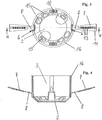
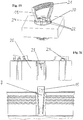
- FIG. 1 to 8 a first embodiment of the invention is shown.
- the Figures 1 to 8 show an installation box 1 made of plastic for electrical purposes.
- the installation box 1 has at least one pot-like box body with a bottom 2 and a peripheral wall 3 protruding from the bottom 2.
- the installation box 1 has means for attachment to or in a perforation of a building wall or a building hollow wall 4.
- the peripheral wall 3 of the installation box 1 has slots 5 running parallel to the central longitudinal axis of the box body over part of its length.
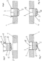
- Spreading means covering the slot 5 are arranged on the wall 3, which, in the position of use of the installation box 1 inserted into the perforation of the hollow building wall 4, spread the circumferential wall 3 in the area of the slot 5 and tighten or hold the circumferential wall 3 against the hole reveal.
- the circumference of the peripheral wall 3 distributed two opposite slots 5 formed and with appropriate expansion means expandable, so that the circumferential wall 3 is spread in the area of the slot 5 and is kept tense against the hole reveal.
- the areas of the peripheral wall 3 adjacent to the slot 5 are in the exemplary embodiment of FIG Figures 1 to 8 Tapered and adjacent to the respective tapered area, a groove-like guide 6 is formed.
- a longitudinal side of a wedge-shaped material strip 7, which forms the expansion means, can be guided in the groove-like guide 6 ( Figures 1 to 6 ) or led ( Figures 7 and 8 ).
- both the groove-like guide 6 and each longitudinal side of the wedge-shaped material strip 7 are shaped like dovetails. This prevents the wedge-shaped material strip 7 from slipping out of the groove-like guide 6 when the wedge-shaped material strip 7 is adjusted within the groove-like guide 6 even when high clamping forces are applied.
- the groove-like guides 6 adjacent to the slot 5 converge towards one another in the direction of the base 2 of the installation box 1.
- the slots 5 and the groove-like guides 3 on the mouth side of the installation box 1 are designed to be open at the edge.
- a dimensionally stable, hard plastic for the production of Installation boxes 1 enables.
- an elastic, not dimensionally stable plastic at least in the vicinity of the slots 5, the open-edge design of the slots 5 is not necessary.
- each wedge-shaped material strip 7 is formed on the outside of the surrounding wall 3 by means of a film hinge 8 in the region of its front end, which is near the bottom 2 in the installation direction, by means of a film hinge 8. This ensures at all times that a sufficient number of wedge-shaped strips of material 7 are carried in the spreading position for bracing the installation box 1. This reduces the number of parts to be stored and kept in stock for the installer on site.
- each wedge-shaped material strip 7 is integrally formed on the inside of the surrounding wall 3 by means of a film hinge in the region of its front end in the installation direction, which is approximated to the bottom 2, by means of a film hinge. This also ensures at all times that a sufficient number of wedge-shaped strips of material 7 are carried in the spread position for bracing the installation box 1. In addition, this solution ensures that the material strips 7 molded on by means of the film hinge do not form an obstacle when the installation box 1 is inserted into the perforation of the building wall or hollow building wall 4 or, if the installer is inattentive, may be separated from the surrounding wall 3 and possibly lost.
- the wedge-shaped material strips 7 formed on the inside of the circumferential wall 3 are thus arranged in a preassembly position within the installation space of the installation box 1 and, for example, are only approximated to the circumferential wall 3 after the installation box 1 has been inserted into the perforation of a building wall or hollow wall 4 and accordingly in the spread position spent.
- the wedge-shaped material strip 7 projects in a non-tensioned pre-assembly position outward of the mouth of the installation box 1 and in particular from Figure 8 can be seen, the wedge-shaped material strip 7 is arranged flush in the tensioned and spread use position to the mouth of the installation box 1.
- each wedge-shaped material strip 7 is easier to handle, for example in that a hook-like tool engages in it and adjusts it from the non-tensioned pre-assembly position into the clamping position.
- means can be arranged on the outside on the circumferential wall 3 which increase the frictional connection and / or the non-positive connection.
- the means can be formed, for example, by a wavy or a trapezoidal surface structure 12.
- the means can also be formed by a rubber coating arranged or applied on the outside of the peripheral wall 3. This rubber coating can, for example, be applied to the circumferential wall 3 using the 2-component process.
- Such projections 13 are tensioned or pressed against the hole reveal when the wedge-shaped material strips 7 are tensioned in the tensioned position, in order thus to increase the hold of the installation box 1 in the installed position.
- breakable or pierceable areas 15 are formed for the feeding and removal of cables, for example. These can be pierced or broken out by the installer on site, as required, in order to lead a corresponding number of cables into or out of the box.
- screw domes 18 are arranged on the inside of the circumferential wall 3 of the installation box 1 and run parallel to the direction of installation.
- the circumferential wall 3 is elastic at least over part of its length.
- the elastic region 17 can be bellows-like pushed into each other and pulled apart as desired or required and thus stretched.
- Such an installation box 1 according to the invention can also be used and used by the installer on site in perforations on a building wall or hollow building wall 4 which have only a small installation depth. The fitter therefore does not have to carry installation boxes 1 with different lengths in order to be able to install them in correspondingly deep perforations.
- the installation box 1 may be necessary to design the installation box 1 accordingly longer in order to provide sufficient space for the cables and / or the installed device put.
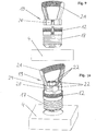
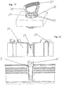
- the invention sets in Figures 9 to 12 Tool 19 shown for assembly and disassembly of an installation box 1 according to the embodiment of the invention.
- the tool 19 has an approximately hollow cylindrical base body 20 with a handle 21 at a first end region.
- the outer diameter of the cylindrical base body 20 is slightly smaller than the inner diameter of the installation box 1 that forms the installation space.
- the cylindrical base body 20 of the tool 19 can be easily inserted into FIGS Installation space of the installation box 1 can be inserted by means of the handle 21.
- the cylindrical base body 20 has opposite ones on the outside Longitudinal groove pairs 22.
- the wedge-shaped material strips 7 are arranged in a first or in a second pair of longitudinal grooves 22 of the tool 19, depending on the intended use of the tool 19, that is to say for mounting or dismantling the installation box 1 by means of the tool 19.
- resilient locking means 23 are arranged in a first pair of longitudinal grooves 22, which engage in the tool engagement holes 11 of the wedge-shaped material strips 7.
- a third and a fourth pair of longitudinal grooves 22 are formed on the tool 19, each of which forms a free space for the screw domes 18 of the installation box 1 in the respective position, that is to say in the assembly position or in the dismantling position of the tool 19.
- Such a tool 19 can be pre-positioned quickly and easily by the installer on site, either in the assembly position or in the disassembly position, on an installation box 1 in order to either assemble or disassemble the installation box 1.
- the tool 19 is partially inserted into the installation space of the installation box 1 in the appropriate position and can either release the installation box 1 in the respective position by engaging the resilient latching means 23 in the tool engagement holes 11 and then dismantle it or by means of the protruding projections 24 exert pressure on the wedge-shaped material strips 7 and adjust them into the clamping position which is flush with the mouth plane and fix the installation box 1 in the position of use.
Landscapes
- Engineering & Computer Science (AREA)
- Architecture (AREA)
- Civil Engineering (AREA)
- Structural Engineering (AREA)
- Connection Or Junction Boxes (AREA)
Claims (20)
- Boîte d'installation (1) en plastique pour des buts électriques, au moins comportant un corps de boîte en forme de pot avec un fond (2) et une paroi circonférentielle (3) s'étendant à partir du fond (2), en outre comportant des moyens pour la fixation à ou dans un trou d'une paroi de bâtiment ou une paroi creuse de bâtiment (4), la paroi circonférentielle (3) comportant en parallèle à l'axe longitudinal central du corps de boîte des fentes (5) s'étendant sur une partie de sa longueur, avec des moyens d'écartement recouvrant la fente (5) étant formés ou disposés à la paroi (3) et, dans sa position d'utilisation de la boîte d'installation (1) insérée dans le trou de la paroi, écartant la paroi circonférentielle (3) dans la zone de la fente (5) et tendant la paroi circonférentielle (3) contre la jambe du trou ou la maintenant appliquée là-contre, les moyens d'écartement étant réglables par manipulation à partir de leur position de pré-montage à une position écartée, dans laquelle la paroi circonférentielle (3) de la boîte d'installation (1) est écartée dans la zone de la fente (6) respective, caractérisée en ce que dans les deux zones voisines à la fente (5), la paroi circonférentielle de la boîte d'installation (1) est diminuée, et voisin à la zone diminuée respective, un guide (6) chacun en forme de rainure est réalisé, dans lequel un côté longitudinal chacun d'une bande de matériau (7) en forme de coin formant les moyens d'écartement peut être guidé ou est guidé, et que la bande de matériau (7) en forme de coin est formée, dans la zone de son extrémité avant, dans la direction de montage, adaptée au fond (2), intérieurement ou extérieurement à la paroi circonférentielle (3) au moyen d'une charnière-film (8).
- Boîte d'installation (1) selon la revendication 1, caractérisée en ce que, réparties sur la périphérie, deux fentes (5) opposées avec des moyens d'écartement correspondants sont réalisées ou arrangées.
- Boîte d'installation (1) selon la revendication 1, caractérisée en ce que les guides (6) en forme de rainure et les côtés longitudinaux de la bande de matériau (7) en forme de coin ont une forme de type queue d'aronde.
- Boîte d'installation (1) selon la revendication 1 ou 3, caractérisée en ce que les guides (6) en forme de rainure voisins à la fente (5) s'étendent de façon convergente entre eux dans la direction du fond (2) de la boîte d'installation (1).
- Boîte d'installation (1) selon une des revendications 1 à 4, caractérisée en ce que les fentes (5) et les guides (3) en forme de rainure sont réalisés avec des arêtes ouvertes vers le côté de l'embouchure de la boîte d'installation (1).
- Boîte d'installation (1) selon une des revendications 1 à 5, caractérisée en ce que la bande de matériau (7) en forme de coin, dans une position de pré-montage non tendue, s'étend au-delà de l'arête de l'embouchure de la boîte d'installation (1) vers l'extérieur, et dans la position d'utilisation tendue, est disposée en affleurement avec l'arête de l'embouchure.
- Boîte d'installation (1) selon une des revendications 1 à 6, caractérisée en ce que chaque bande de matériau (7) en forme de coin comporte un accès pour un outil.
- Boîte d'installation (1) selon la revendication 7, caractérisée en ce que l'accès pour un outil consiste en un trou (11) carré ou rectangulaire.
- Boîte d'installation (1) selon une des revendications 1 à 8, caractérisée en ce que la paroi circonférentielle (3) comprend des moyens sur l'extérieur qui augmentent la valeur de la friction et/ou de la force par rapport à la jambe du trou.
- Boîte d'installation (1) selon la revendication 9, caractérisée en ce que les moyens sont réalisés par une structure de surface (12) en forme d'ondes ou de trapèze.
- Boîte d'installation (1) selon la revendication 9 ou 10, caractérisée en ce que les moyens sont réalisés par une couche de gomme disposée ou appliquée à l'extérieur sur la paroi circonférentielle (3).
- Boîte d'installation (1) selon une des revendications 1 à 11, caractérisée en ce que les bandes de matériau (7) comportent des saillies (13) augmentant la valeur de la friction et/ou de la force par rapport à la jambe du trou et faisant saillie vers l'extérieur.
- Boîte d'installation (1) selon la revendication 12, caractérisée en ce que plusieurs saillies (13) successives sont disposées à l'extérieur sur la bande de matériau (7), la hauteur des saillies (13) se diminuant à partir du plan formé par l'embouchure de la boîte d'installation (1) dans la direction du fond (2) de la boîte d'installation (1).
- Boîte d'installation (1) selon une des revendications 1 à 11, caractérisée en ce que le fond (2) du corps de boîte est formé de façon tronconique (à 14), à partir de l'intérieur de la boîte vers la paroi circonférentielle (3).
- Boîte d'installation (1) selon la revendication 1, caractérisée en ce que dans le fond (2) de la boîte d'installation ou dans une zone tronconique (14), des zones (15) à être arrachées ou percées sont réalisées.
- Boîte d'installation (1) selon une des revendications 1 à 13, caractérisée en ce que la paroi circonférentielle (3) comporte à son extrémité libre au côté de l'embouchure un collier (16) s'étendant vers l'extérieur et formant une arête de bride.
- Boîte d'installation (1) selon une des revendications 1 à 16, caractérisée en ce que la paroi circonférentielle (3) est réalisée de façon élastique au moins sur une partie de sa longueur.
- Boîte d'installation (1) selon la revendication 17, caractérisée en ce que la partie élastique (17) peut être resserrée ou est resserrée et peut être étirée ou est étirée de façon de soufflet.
- Boîte d'installation (1) selon une des revendications 1 à 18, caractérisée en ce qu' à l'intérieur de la paroi circonférentielle (3) de la boîte d'installation (1), des bossages pour vis (18) s'étendant en parallèle à la direction de montage sont disposés.
- Outil (19) pour le montage et le démontage d'une boîte d'installation (1) selon une ou plusieurs revendications 1 à 19, dans lequel l'outil (19) comporte un corps principal (20) environ en forme d'un cylindre creux avec une poignée (21) à une partie d'extrémité, et dans lequel le diamètre extérieur du corps principal (20) cylindrique est légèrement inférieur au diamètre intérieur de la boîte d'installation (1) formant l'espace d'installation, de façon que le corps principal (20) cylindrique de l'outil (19) puisse être inséré au moyen de la poignée (21) dans l'espace d'installation de la boîte d'installation (1), caractérisée en ce que le corps principal (20) cylindrique comporte sur son extérieur des paires opposés de rainures longitudinales (22), à l'intérieur desquelles, dans la position d'utilisation de l'outil (19), des parties de la boîte d'installation (1), c'est-à-dire les bandes de matériau (7) en forme de coin sont disposées, dans un premier paire de rainures longitudinales (22) des moyens d'encliquetage (23) résilients étant disposés qui s'engagent dans des trous d'engagement de l'outil (11) des bandes de matériau (7) en forme de coin, et à un deuxième paire de rainures longitudinales (22) une saillie (24) chacune s'étendant vers l'extérieur de l'extrémité à l'embouchure est réalisée qui dans la position de montage respectivement s'étend sur le front des moyens d'écartement formés par les bandes de matériau (7) en forme de coin, en outre un troisième et un quatrième paire de rainures longitudinales (22) étant prévus, qui forment un espace libre respectif pour les bossages pour vis.
Applications Claiming Priority (1)
| Application Number | Priority Date | Filing Date | Title |
|---|---|---|---|
| DE102015112420.3A DE102015112420A1 (de) | 2015-07-29 | 2015-07-29 | Installationsdose |
Publications (2)
| Publication Number | Publication Date |
|---|---|
| EP3125384A1 EP3125384A1 (fr) | 2017-02-01 |
| EP3125384B1 true EP3125384B1 (fr) | 2020-02-26 |
Family
ID=56611198
Family Applications (1)
| Application Number | Title | Priority Date | Filing Date |
|---|---|---|---|
| EP16181361.3A Active EP3125384B1 (fr) | 2015-07-29 | 2016-07-27 | Boitier d'installation |
Country Status (2)
| Country | Link |
|---|---|
| EP (1) | EP3125384B1 (fr) |
| DE (1) | DE102015112420A1 (fr) |
Families Citing this family (10)
| Publication number | Priority date | Publication date | Assignee | Title |
|---|---|---|---|---|
| DE202018006675U1 (de) * | 2018-03-14 | 2022-01-17 | Kaiser Gmbh & Co. Kg | Installationsdose |
| DE202018101937U1 (de) | 2018-04-10 | 2019-04-11 | F-Tronic Gmbh | Installationsmaterial für die Elektroinstallation in Hohlwänden |
| DE102018009768A1 (de) | 2018-12-17 | 2020-06-18 | Truma Gerätetechnik GmbH & Co. KG | Haltevorrichtung für eine Komponente |
| DE102019131367A1 (de) * | 2019-11-20 | 2021-05-20 | Kaiser Gmbh & Co. Kg | Installationsdose |
| DE102020103805B4 (de) * | 2020-02-13 | 2026-02-19 | Herbert Wintersteiger | Elektroinstallationsdose mit angeformten Rastzähnen |
| DE102020203797A1 (de) | 2020-03-24 | 2021-09-30 | Hansgrohe Se | Wandeinbau-Anschlussboxeinheit mit Verlängerungshülse |
| DE102020203792A1 (de) | 2020-03-24 | 2021-09-30 | Hansgrohe Se | Wandeinbau-Anschlussboxeinheit |
| DE102020203800A1 (de) | 2020-03-24 | 2021-09-30 | Hansgrohe Se | Sanitäre Wandeinbau-Anschlussboxeinheit mit elektrischer Leitungsdurchführung |
| DE102020203794A1 (de) | 2020-03-24 | 2021-09-30 | Hansgrohe Se | Wandeinbau-Anschlussboxeinheit mit Funktionsflächenkörper |
| DE202023106677U1 (de) * | 2023-11-14 | 2023-12-19 | F-Tronic Gmbh | Befestigungshülse |
Citations (2)
| Publication number | Priority date | Publication date | Assignee | Title |
|---|---|---|---|---|
| FR2339318A1 (fr) * | 1976-01-26 | 1977-08-19 | Badoux Daniel | Perfectionnements aux boitiers porte-appareillage pour installations electriques du type encastre |
| FR2881286A1 (fr) * | 2005-01-26 | 2006-07-28 | Boulay Accessoires De Derivati | Boitier pour connexions electriques, destine a etre monte dans un logement |
Family Cites Families (11)
| Publication number | Priority date | Publication date | Assignee | Title |
|---|---|---|---|---|
| DE4101979A1 (de) * | 1991-01-24 | 1992-07-30 | Kaiser Gmbh & Co Kg | Elektrische hohlwanddose |
| DE4241989A1 (de) * | 1992-12-12 | 1994-06-16 | Grohe Armaturen Friedrich | Unterputz-Armatur |
| DE4342512C2 (de) * | 1993-12-09 | 1995-09-21 | Ludwig Schroeder | Elektrische Einbaudose |
| AT404080B (de) * | 1994-11-04 | 1998-08-25 | Putz Georg | Elektroinstallationsdose für die montage in wänden, insbesondere hohlwänden |
| FR2781097B1 (fr) * | 1998-07-08 | 2000-10-13 | Legrand Sa | Boite d'encastrement pour cloison seche a patte(s) de serrage initialement d'un seul tenant, notamment pour appareillage electrique |
| DE19848475A1 (de) * | 1998-10-21 | 2000-04-27 | Klaus Steinbrecher | Positionierhilfe für runde Bauelemente, insbesondere für das Ausrichten und nachträglichem Positionieren von Hohlwandschalter- und/bzw. Hohlwandschalterklemmdosen u. dgl. |
| EP1303017A1 (fr) * | 2001-10-10 | 2003-04-16 | Adolf Würth GmbH & Co. KG | Boíte pour cloison sèche |
| NL1031723C2 (nl) * | 2006-04-28 | 2007-11-05 | Abb Bv | Doos voor electrische installaties, voorzien van plaatsingsmiddelen. |
| FR2923326B1 (fr) * | 2007-11-05 | 2010-01-22 | Thierry Fournier | Boitier encastrable dans une cloison |
| US7586039B1 (en) * | 2008-01-09 | 2009-09-08 | Arlington Industries, Inc. | Hole saw electrical box for direct mounting of electrical fixtures or devices to a wall |
| EP2273637B1 (fr) * | 2009-07-09 | 2017-05-24 | Kaiser GmbH & Co. KG | Dispositif destiné au passage étanche aux gaz de combustion d'un élément longitudinal à travers un mur |
-
2015
- 2015-07-29 DE DE102015112420.3A patent/DE102015112420A1/de not_active Withdrawn
-
2016
- 2016-07-27 EP EP16181361.3A patent/EP3125384B1/fr active Active
Patent Citations (2)
| Publication number | Priority date | Publication date | Assignee | Title |
|---|---|---|---|---|
| FR2339318A1 (fr) * | 1976-01-26 | 1977-08-19 | Badoux Daniel | Perfectionnements aux boitiers porte-appareillage pour installations electriques du type encastre |
| FR2881286A1 (fr) * | 2005-01-26 | 2006-07-28 | Boulay Accessoires De Derivati | Boitier pour connexions electriques, destine a etre monte dans un logement |
Also Published As
| Publication number | Publication date |
|---|---|
| DE102015112420A1 (de) | 2017-02-02 |
| EP3125384A1 (fr) | 2017-02-01 |
Similar Documents
| Publication | Publication Date | Title |
|---|---|---|
| EP3125384B1 (fr) | Boitier d'installation | |
| EP1065426B1 (fr) | Dispositif de raccordement pour la fixation d'objets allongés | |
| EP2587106B1 (fr) | Manchette pare-feu | |
| EP0943856A2 (fr) | Dispositif de raccordement avec saillie de montage | |
| AT515988A2 (de) | Leuchte, Anordnung für eine Rasterdecke, Verfahren zum Montieren einer Leuchte, Verfahren zum Demontieren einer Leuchte, sowie Demontagewerkzeug | |
| EP1774184A1 (fr) | Rivet a expansion | |
| EP0671581A2 (fr) | Rail de montage pour la fixation de tuyaux ou similaires | |
| DE202016103068U1 (de) | Blindbefestigungsvorrichtung zur Befestigung eines Bauteils | |
| DE102013003133A1 (de) | Dachrelinghalter sowie Dachrelinganordnung und Fahrzeug mit der Dachrelinganordnung | |
| EP3584898B1 (fr) | Boîte d'installation | |
| EP3122981A2 (fr) | Dispositif d'étanchéité et moyen de fixation | |
| WO2005017372A1 (fr) | Dispositif comportant deux profiles creux assembles par une vis et outil correspondant | |
| EP3369946B1 (fr) | Cheville plate et procédé de montage d'une cheville plate dans une paroi | |
| EP3421708B1 (fr) | Jeu d'ajustage en plusieurs pièces destiné au montage espacé d'un cadre à une douelle | |
| DE102014102260B4 (de) | Baukasten für die Abdichtung des Durchganges von Kabeln oder Adern, die durch eine Platte verlaufen sowie Verfahren zum Abdichten | |
| DE202004011202U1 (de) | Moduldichtung für Leitungsdurchführungen | |
| DE4408419A1 (de) | Montageschiene zur Befestigung von Rohren oder dergleichen Gegenständen | |
| EP3303062B1 (fr) | Arrangement pour la fixation d'un element en forme de reglette | |
| DE102012107009A1 (de) | Dübel | |
| EP3692615B1 (fr) | Manchon de montage | |
| DE3109885A1 (de) | Elektrische leuchte zum einbau in vorgefertigte zwischendecken | |
| EP3486400A1 (fr) | Sous-construction pour un revêtement de façade et procédé de montage d'une sous-construction | |
| DE102025103033A1 (de) | Installationsdose | |
| DE7700802U1 (de) | Schallisolierende rohrschelle | |
| EP3364053B1 (fr) | Cheville à expansion |
Legal Events
| Date | Code | Title | Description |
|---|---|---|---|
| PUAI | Public reference made under article 153(3) epc to a published international application that has entered the european phase |
Free format text: ORIGINAL CODE: 0009012 |
|
| STAA | Information on the status of an ep patent application or granted ep patent |
Free format text: STATUS: THE APPLICATION HAS BEEN PUBLISHED |
|
| AK | Designated contracting states |
Kind code of ref document: A1 Designated state(s): AL AT BE BG CH CY CZ DE DK EE ES FI FR GB GR HR HU IE IS IT LI LT LU LV MC MK MT NL NO PL PT RO RS SE SI SK SM TR |
|
| AX | Request for extension of the european patent |
Extension state: BA ME |
|
| STAA | Information on the status of an ep patent application or granted ep patent |
Free format text: STATUS: REQUEST FOR EXAMINATION WAS MADE |
|
| 17P | Request for examination filed |
Effective date: 20170613 |
|
| RBV | Designated contracting states (corrected) |
Designated state(s): AL AT BE BG CH CY CZ DE DK EE ES FI FR GB GR HR HU IE IS IT LI LT LU LV MC MK MT NL NO PL PT RO RS SE SI SK SM TR |
|
| STAA | Information on the status of an ep patent application or granted ep patent |
Free format text: STATUS: EXAMINATION IS IN PROGRESS |
|
| 17Q | First examination report despatched |
Effective date: 20171013 |
|
| GRAP | Despatch of communication of intention to grant a patent |
Free format text: ORIGINAL CODE: EPIDOSNIGR1 |
|
| STAA | Information on the status of an ep patent application or granted ep patent |
Free format text: STATUS: GRANT OF PATENT IS INTENDED |
|
| INTG | Intention to grant announced |
Effective date: 20191023 |
|
| GRAS | Grant fee paid |
Free format text: ORIGINAL CODE: EPIDOSNIGR3 |
|
| GRAA | (expected) grant |
Free format text: ORIGINAL CODE: 0009210 |
|
| STAA | Information on the status of an ep patent application or granted ep patent |
Free format text: STATUS: THE PATENT HAS BEEN GRANTED |
|
| AK | Designated contracting states |
Kind code of ref document: B1 Designated state(s): AL AT BE BG CH CY CZ DE DK EE ES FI FR GB GR HR HU IE IS IT LI LT LU LV MC MK MT NL NO PL PT RO RS SE SI SK SM TR |
|
| REG | Reference to a national code |
Ref country code: GB Ref legal event code: FG4D Free format text: NOT ENGLISH |
|
| REG | Reference to a national code |
Ref country code: CH Ref legal event code: NV Representative=s name: TROESCH SCHEIDEGGER WERNER AG, CH Ref country code: CH Ref legal event code: EP |
|
| REG | Reference to a national code |
Ref country code: DE Ref legal event code: R096 Ref document number: 502016008893 Country of ref document: DE |
|
| REG | Reference to a national code |
Ref country code: AT Ref legal event code: REF Ref document number: 1238808 Country of ref document: AT Kind code of ref document: T Effective date: 20200315 |
|
| REG | Reference to a national code |
Ref country code: IE Ref legal event code: FG4D Free format text: LANGUAGE OF EP DOCUMENT: GERMAN |
|
| REG | Reference to a national code |
Ref country code: NL Ref legal event code: FP |
|
| PG25 | Lapsed in a contracting state [announced via postgrant information from national office to epo] |
Ref country code: RS Free format text: LAPSE BECAUSE OF FAILURE TO SUBMIT A TRANSLATION OF THE DESCRIPTION OR TO PAY THE FEE WITHIN THE PRESCRIBED TIME-LIMIT Effective date: 20200226 Ref country code: FI Free format text: LAPSE BECAUSE OF FAILURE TO SUBMIT A TRANSLATION OF THE DESCRIPTION OR TO PAY THE FEE WITHIN THE PRESCRIBED TIME-LIMIT Effective date: 20200226 Ref country code: NO Free format text: LAPSE BECAUSE OF FAILURE TO SUBMIT A TRANSLATION OF THE DESCRIPTION OR TO PAY THE FEE WITHIN THE PRESCRIBED TIME-LIMIT Effective date: 20200526 |
|
| REG | Reference to a national code |
Ref country code: LT Ref legal event code: MG4D |
|
| PG25 | Lapsed in a contracting state [announced via postgrant information from national office to epo] |
Ref country code: BG Free format text: LAPSE BECAUSE OF FAILURE TO SUBMIT A TRANSLATION OF THE DESCRIPTION OR TO PAY THE FEE WITHIN THE PRESCRIBED TIME-LIMIT Effective date: 20200526 Ref country code: IS Free format text: LAPSE BECAUSE OF FAILURE TO SUBMIT A TRANSLATION OF THE DESCRIPTION OR TO PAY THE FEE WITHIN THE PRESCRIBED TIME-LIMIT Effective date: 20200626 Ref country code: HR Free format text: LAPSE BECAUSE OF FAILURE TO SUBMIT A TRANSLATION OF THE DESCRIPTION OR TO PAY THE FEE WITHIN THE PRESCRIBED TIME-LIMIT Effective date: 20200226 Ref country code: LV Free format text: LAPSE BECAUSE OF FAILURE TO SUBMIT A TRANSLATION OF THE DESCRIPTION OR TO PAY THE FEE WITHIN THE PRESCRIBED TIME-LIMIT Effective date: 20200226 Ref country code: SE Free format text: LAPSE BECAUSE OF FAILURE TO SUBMIT A TRANSLATION OF THE DESCRIPTION OR TO PAY THE FEE WITHIN THE PRESCRIBED TIME-LIMIT Effective date: 20200226 |
|
| PG25 | Lapsed in a contracting state [announced via postgrant information from national office to epo] |
Ref country code: PT Free format text: LAPSE BECAUSE OF FAILURE TO SUBMIT A TRANSLATION OF THE DESCRIPTION OR TO PAY THE FEE WITHIN THE PRESCRIBED TIME-LIMIT Effective date: 20200719 Ref country code: DK Free format text: LAPSE BECAUSE OF FAILURE TO SUBMIT A TRANSLATION OF THE DESCRIPTION OR TO PAY THE FEE WITHIN THE PRESCRIBED TIME-LIMIT Effective date: 20200226 Ref country code: ES Free format text: LAPSE BECAUSE OF FAILURE TO SUBMIT A TRANSLATION OF THE DESCRIPTION OR TO PAY THE FEE WITHIN THE PRESCRIBED TIME-LIMIT Effective date: 20200226 Ref country code: RO Free format text: LAPSE BECAUSE OF FAILURE TO SUBMIT A TRANSLATION OF THE DESCRIPTION OR TO PAY THE FEE WITHIN THE PRESCRIBED TIME-LIMIT Effective date: 20200226 Ref country code: CZ Free format text: LAPSE BECAUSE OF FAILURE TO SUBMIT A TRANSLATION OF THE DESCRIPTION OR TO PAY THE FEE WITHIN THE PRESCRIBED TIME-LIMIT Effective date: 20200226 Ref country code: EE Free format text: LAPSE BECAUSE OF FAILURE TO SUBMIT A TRANSLATION OF THE DESCRIPTION OR TO PAY THE FEE WITHIN THE PRESCRIBED TIME-LIMIT Effective date: 20200226 Ref country code: LT Free format text: LAPSE BECAUSE OF FAILURE TO SUBMIT A TRANSLATION OF THE DESCRIPTION OR TO PAY THE FEE WITHIN THE PRESCRIBED TIME-LIMIT Effective date: 20200226 Ref country code: SM Free format text: LAPSE BECAUSE OF FAILURE TO SUBMIT A TRANSLATION OF THE DESCRIPTION OR TO PAY THE FEE WITHIN THE PRESCRIBED TIME-LIMIT Effective date: 20200226 Ref country code: SK Free format text: LAPSE BECAUSE OF FAILURE TO SUBMIT A TRANSLATION OF THE DESCRIPTION OR TO PAY THE FEE WITHIN THE PRESCRIBED TIME-LIMIT Effective date: 20200226 |
|
| REG | Reference to a national code |
Ref country code: DE Ref legal event code: R097 Ref document number: 502016008893 Country of ref document: DE |
|
| PLBE | No opposition filed within time limit |
Free format text: ORIGINAL CODE: 0009261 |
|
| STAA | Information on the status of an ep patent application or granted ep patent |
Free format text: STATUS: NO OPPOSITION FILED WITHIN TIME LIMIT |
|
| PG25 | Lapsed in a contracting state [announced via postgrant information from national office to epo] |
Ref country code: IT Free format text: LAPSE BECAUSE OF FAILURE TO SUBMIT A TRANSLATION OF THE DESCRIPTION OR TO PAY THE FEE WITHIN THE PRESCRIBED TIME-LIMIT Effective date: 20200226 |
|
| 26N | No opposition filed |
Effective date: 20201127 |
|
| PG25 | Lapsed in a contracting state [announced via postgrant information from national office to epo] |
Ref country code: SI Free format text: LAPSE BECAUSE OF FAILURE TO SUBMIT A TRANSLATION OF THE DESCRIPTION OR TO PAY THE FEE WITHIN THE PRESCRIBED TIME-LIMIT Effective date: 20200226 Ref country code: PL Free format text: LAPSE BECAUSE OF FAILURE TO SUBMIT A TRANSLATION OF THE DESCRIPTION OR TO PAY THE FEE WITHIN THE PRESCRIBED TIME-LIMIT Effective date: 20200226 Ref country code: MC Free format text: LAPSE BECAUSE OF FAILURE TO SUBMIT A TRANSLATION OF THE DESCRIPTION OR TO PAY THE FEE WITHIN THE PRESCRIBED TIME-LIMIT Effective date: 20200226 |
|
| GBPC | Gb: european patent ceased through non-payment of renewal fee |
Effective date: 20200727 |
|
| PG25 | Lapsed in a contracting state [announced via postgrant information from national office to epo] |
Ref country code: GB Free format text: LAPSE BECAUSE OF NON-PAYMENT OF DUE FEES Effective date: 20200727 Ref country code: LU Free format text: LAPSE BECAUSE OF NON-PAYMENT OF DUE FEES Effective date: 20200727 |
|
| PG25 | Lapsed in a contracting state [announced via postgrant information from national office to epo] |
Ref country code: IE Free format text: LAPSE BECAUSE OF NON-PAYMENT OF DUE FEES Effective date: 20200727 |
|
| PG25 | Lapsed in a contracting state [announced via postgrant information from national office to epo] |
Ref country code: TR Free format text: LAPSE BECAUSE OF FAILURE TO SUBMIT A TRANSLATION OF THE DESCRIPTION OR TO PAY THE FEE WITHIN THE PRESCRIBED TIME-LIMIT Effective date: 20200226 Ref country code: MT Free format text: LAPSE BECAUSE OF FAILURE TO SUBMIT A TRANSLATION OF THE DESCRIPTION OR TO PAY THE FEE WITHIN THE PRESCRIBED TIME-LIMIT Effective date: 20200226 Ref country code: CY Free format text: LAPSE BECAUSE OF FAILURE TO SUBMIT A TRANSLATION OF THE DESCRIPTION OR TO PAY THE FEE WITHIN THE PRESCRIBED TIME-LIMIT Effective date: 20200226 |
|
| PG25 | Lapsed in a contracting state [announced via postgrant information from national office to epo] |
Ref country code: MK Free format text: LAPSE BECAUSE OF FAILURE TO SUBMIT A TRANSLATION OF THE DESCRIPTION OR TO PAY THE FEE WITHIN THE PRESCRIBED TIME-LIMIT Effective date: 20200226 Ref country code: AL Free format text: LAPSE BECAUSE OF FAILURE TO SUBMIT A TRANSLATION OF THE DESCRIPTION OR TO PAY THE FEE WITHIN THE PRESCRIBED TIME-LIMIT Effective date: 20200226 |
|
| PG25 | Lapsed in a contracting state [announced via postgrant information from national office to epo] |
Ref country code: GR Free format text: LAPSE BECAUSE OF FAILURE TO SUBMIT A TRANSLATION OF THE DESCRIPTION OR TO PAY THE FEE WITHIN THE PRESCRIBED TIME-LIMIT Effective date: 20200226 |
|
| PGFP | Annual fee paid to national office [announced via postgrant information from national office to epo] |
Ref country code: NL Payment date: 20230721 Year of fee payment: 8 |
|
| PGFP | Annual fee paid to national office [announced via postgrant information from national office to epo] |
Ref country code: CH Payment date: 20230801 Year of fee payment: 8 Ref country code: AT Payment date: 20230721 Year of fee payment: 8 |
|
| PGFP | Annual fee paid to national office [announced via postgrant information from national office to epo] |
Ref country code: FR Payment date: 20230724 Year of fee payment: 8 Ref country code: BE Payment date: 20230721 Year of fee payment: 8 |
|
| REG | Reference to a national code |
Ref country code: CH Ref legal event code: PL |
|
| REG | Reference to a national code |
Ref country code: NL Ref legal event code: MM Effective date: 20240801 |
|
| REG | Reference to a national code |
Ref country code: AT Ref legal event code: MM01 Ref document number: 1238808 Country of ref document: AT Kind code of ref document: T Effective date: 20240727 |
|
| PG25 | Lapsed in a contracting state [announced via postgrant information from national office to epo] |
Ref country code: NL Free format text: LAPSE BECAUSE OF NON-PAYMENT OF DUE FEES Effective date: 20240801 |
|
| PG25 | Lapsed in a contracting state [announced via postgrant information from national office to epo] |
Ref country code: CH Free format text: LAPSE BECAUSE OF NON-PAYMENT OF DUE FEES Effective date: 20240731 Ref country code: AT Free format text: LAPSE BECAUSE OF NON-PAYMENT OF DUE FEES Effective date: 20240727 Ref country code: BE Free format text: LAPSE BECAUSE OF NON-PAYMENT OF DUE FEES Effective date: 20240731 |
|
| PG25 | Lapsed in a contracting state [announced via postgrant information from national office to epo] |
Ref country code: FR Free format text: LAPSE BECAUSE OF NON-PAYMENT OF DUE FEES Effective date: 20240731 |
|
| REG | Reference to a national code |
Ref country code: BE Ref legal event code: MM Effective date: 20240731 |
|
| PGFP | Annual fee paid to national office [announced via postgrant information from national office to epo] |
Ref country code: DE Payment date: 20250930 Year of fee payment: 10 |
|
| REG | Reference to a national code |
Ref country code: DE Ref legal event code: R082 Ref document number: 502016008893 Country of ref document: DE Representative=s name: KOECHLING, MARIETTA, M.SC B.ENG., DE |