EP3125400A2 - Procédé et dispositif de charge d'alimentation - Google Patents
Procédé et dispositif de charge d'alimentation Download PDFInfo
- Publication number
- EP3125400A2 EP3125400A2 EP16180426.5A EP16180426A EP3125400A2 EP 3125400 A2 EP3125400 A2 EP 3125400A2 EP 16180426 A EP16180426 A EP 16180426A EP 3125400 A2 EP3125400 A2 EP 3125400A2
- Authority
- EP
- European Patent Office
- Prior art keywords
- electronic device
- real
- charging
- connection
- voltage information
- Prior art date
- Legal status (The legal status is an assumption and is not a legal conclusion. Google has not performed a legal analysis and makes no representation as to the accuracy of the status listed.)
- Pending
Links
Images


Classifications
-
- H—ELECTRICITY
- H01—ELECTRIC ELEMENTS
- H01M—PROCESSES OR MEANS, e.g. BATTERIES, FOR THE DIRECT CONVERSION OF CHEMICAL ENERGY INTO ELECTRICAL ENERGY
- H01M10/00—Secondary cells; Manufacture thereof
- H01M10/42—Methods or arrangements for servicing or maintenance of secondary cells or secondary half-cells
- H01M10/44—Methods for charging or discharging
-
- H—ELECTRICITY
- H02—GENERATION; CONVERSION OR DISTRIBUTION OF ELECTRIC POWER
- H02J—ELECTRIC POWER NETWORKS; CIRCUIT ARRANGEMENTS OR SYSTEMS FOR SUPPLYING OR DISTRIBUTING ELECTRIC POWER; SYSTEMS FOR STORING ELECTRIC ENERGY
- H02J7/00—Circuit arrangements for charging or discharging batteries or for supplying loads from batteries
- H02J7/34—Parallel operation in networks using both storage and other DC sources, e.g. providing buffering
- H02J7/342—The other DC source being a battery actively interacting with the first one, i.e. battery to battery charging
-
- H—ELECTRICITY
- H02—GENERATION; CONVERSION OR DISTRIBUTION OF ELECTRIC POWER
- H02J—ELECTRIC POWER NETWORKS; CIRCUIT ARRANGEMENTS OR SYSTEMS FOR SUPPLYING OR DISTRIBUTING ELECTRIC POWER; SYSTEMS FOR STORING ELECTRIC ENERGY
- H02J7/00—Circuit arrangements for charging or discharging batteries or for supplying loads from batteries
- H02J7/90—Regulation of charging or discharging current or voltage
- H02J7/96—Regulation of charging or discharging current or voltage in response to battery voltage
- H02J7/963—Regulation of charging or discharging current or voltage in response to battery voltage in response to battery voltage gradient
-
- H—ELECTRICITY
- H02—GENERATION; CONVERSION OR DISTRIBUTION OF ELECTRIC POWER
- H02J—ELECTRIC POWER NETWORKS; CIRCUIT ARRANGEMENTS OR SYSTEMS FOR SUPPLYING OR DISTRIBUTING ELECTRIC POWER; SYSTEMS FOR STORING ELECTRIC ENERGY
- H02J7/00—Circuit arrangements for charging or discharging batteries or for supplying loads from batteries
- H02J7/40—Circuit arrangements for charging or discharging batteries or for supplying loads from batteries characterised by the exchange of charge or discharge related data
- H02J7/42—Circuit arrangements for charging or discharging batteries or for supplying loads from batteries characterised by the exchange of charge or discharge related data with electronic devices having internal batteries, e.g. mobile phones
-
- Y—GENERAL TAGGING OF NEW TECHNOLOGICAL DEVELOPMENTS; GENERAL TAGGING OF CROSS-SECTIONAL TECHNOLOGIES SPANNING OVER SEVERAL SECTIONS OF THE IPC; TECHNICAL SUBJECTS COVERED BY FORMER USPC CROSS-REFERENCE ART COLLECTIONS [XRACs] AND DIGESTS
- Y02—TECHNOLOGIES OR APPLICATIONS FOR MITIGATION OR ADAPTATION AGAINST CLIMATE CHANGE
- Y02B—CLIMATE CHANGE MITIGATION TECHNOLOGIES RELATED TO BUILDINGS, e.g. HOUSING, HOUSE APPLIANCES OR RELATED END-USER APPLICATIONS
- Y02B40/00—Technologies aiming at improving the efficiency of home appliances, e.g. induction cooking or efficient technologies for refrigerators, freezers or dish washers
-
- Y—GENERAL TAGGING OF NEW TECHNOLOGICAL DEVELOPMENTS; GENERAL TAGGING OF CROSS-SECTIONAL TECHNOLOGIES SPANNING OVER SEVERAL SECTIONS OF THE IPC; TECHNICAL SUBJECTS COVERED BY FORMER USPC CROSS-REFERENCE ART COLLECTIONS [XRACs] AND DIGESTS
- Y02—TECHNOLOGIES OR APPLICATIONS FOR MITIGATION OR ADAPTATION AGAINST CLIMATE CHANGE
- Y02E—REDUCTION OF GREENHOUSE GAS [GHG] EMISSIONS, RELATED TO ENERGY GENERATION, TRANSMISSION OR DISTRIBUTION
- Y02E60/00—Enabling technologies; Technologies with a potential or indirect contribution to GHG emissions mitigation
- Y02E60/10—Energy storage using batteries
Definitions
- the present disclosure generally relates to the field of electronic technology, and more particularly, to a method and device for power charging.
- both a first electronic device and a second electronic device are provided with a battery.
- the method for charging includes the following steps: converting, by the first electronic device though its power management module, a voltage outputted from a battery of the first electronic device to a fixed voltage, the first electronic device being a charging device; inputting the fixed voltage to the second electronic device, the second electronic device being a device to be charged; acquiring in real time, by the second electronic device, a required charging voltage according to charged state of a battery of the second electronic device, the required charging voltage varying with the charged state of the battery of the second electronic device; converting, by the second electronic device though its power management module, the fixed voltage to the required charging voltage such that the second electronic device is charged with the converted charging voltage.
- there are two voltage conversions in the method for charging in which one is performed by the first electronic device, and the other is performed by the second electronic device.
- a method for power charging including: establishing a connection of a first electronic device with a second electronic device; acquiring, by the second electronic device based on the connection, real-time charged voltage information of the first electronic device, the real-time charged voltage information varying with charged state of the first electronic device; and controlling, during charging the first electronic device by the second electronic device, the second electronic device to output a charging voltage to the first electronic device according to the real-time charged voltage information of the first electronic device to charge the first electronic device.
- the establishing a connection of a first electronic device with a second electronic device may include: establishing the connection of the first electronic device with the second electronic device by using designated interfaces provided respectively on the first electronic device and the second electronic device and a designated type of data line between the first electronic device and the second electronic device.
- the first electronic device and the second electronic device both are mobile terminals, or the first electronic device is a mobile terminal and the second electronic device is a mobile power supply device.
- a method for power charging including: establishing a connection of a first electronic device with a second electronic device; detecting in real time charged state of the first electronic device and acquiring real-time charged voltage information of the first electronic device during the first electronic device being charged by the second electronic device, the real-time charged voltage information varying with the charged state of the first electronic device; and transmitting in real time, based on the connection, the real-time charged voltage information of the first electronic device to the second electronic device such that the second electronic device controls a charging voltage outputted from the second electronic device to charge the first electronic device.
- the establishing a connection of a first electronic device with a second electronic device may include: establishing the connection of the first electronic device with the second electronic device by using designated interfaces provided respectively on the first electronic device and the second electronic device and a designated type of data line between the first electronic device and the second electronic device.
- the detecting in real time charged state of the first electronic device and acquiring real-time charged voltage information of the first electronic device may include: acquiring a preset current value multiplied by a present equivalent resistance of a battery as the real-time charged voltage information of the first electronic device when the charged state indicates that a present voltage value of the battery is smaller than a preset value, the equivalent resistance of the battery varying with the charged state of the first electronic device; and acquiring a preset voltage value as the real-time charged voltage information of the first electronic device when the charged state indicates that a present voltage value of the battery is greater than a preset value.
- a device for power charging including: a connection module configured to establish a connection of a first electronic device with a second electronic device; an acquisition module configured to acquire, based on the connection, real-time charged voltage information of the first electronic device, real-time charged voltage information varying with charged state of the first electronic device; and a control module configured to control, during charging the first electronic device, the device to output a charging voltage to the first electronic device according to the real-time charged voltage information of the first electronic device to charge the first electronic device.
- connection module is further configured to establish the connection of the first electronic device with the second electronic device by using designated interfaces provided respectively on the first electronic device and the second electronic device and a designated type of data line between the first electronic device and the second electronic device.
- the first electronic device and the second electronic device both are mobile terminals, or the first electronic device is a mobile terminal and the second electronic device is a mobile power supply device.
- a device for power charging including: a connection module configured to establish a connection of a first electronic device with a second electronic device; an acquisition module configured to detect in real time charged state of the first electronic device and acquire real-time charged voltage information of the first electronic device during the first electronic device being charged by the second electronic device, the real-time charged voltage information varying with the charged state of the first electronic device; and a transmission module configured to transmit in real time, based on the connection, the real-time charged voltage information of the first electronic device to the second electronic device such that the second electronic device controls a charging voltage outputted from the second electronic device to charge the first electronic device.
- connection module is further configured to establish the connection of the first electronic device with the second electronic device by using designated interfaces provided respectively on the first electronic device and the second electronic device and a designated type of data line between the first electronic device and the second electronic device.
- the acquisition module is further configured to acquire a preset current value multiplied by a present equivalent resistance of a battery as the real-time charged voltage information of the first electronic device when the charged state indicates that a present voltage value of the battery is smaller than a preset value, the equivalent resistance of the battery varying with the charged state of the first electronic device, and acquire a preset voltage value as the real-time charged voltage information of the first electronic device when the charged state indicates that a present voltage value of the battery is greater than a preset value.
- an electronic device comprising: a processor; a memory for storing instructions executable by the processor, wherein the processor is configured to: establish a connection with a first electronic device, acquire, based on the connection, real-time charged voltage information of the first electronic device, the real-time charged voltage information varying with charged state of the first electronic device, and control, during charging the first electronic device, the electronic device to output a charging voltage to the first electronic device according to the real-time charged voltage information of the first electronic device to charge the first electronic device.
- an electronic device comprising: a processor; a memory for storing instructions executable by the processor, wherein the processor is configured to: establish a connection with a second electronic device, detect in real time charged state of the electronic device and acquiring real-time charged voltage information of the electronic device during the electronic device being charged by the second electronic device, the real-time charged voltage information varying with charged state of the electronic device, and transmit in real time, based on the connection, the real-time charged voltage information to the second electronic device such that the second electronic device controls a charging voltage outputted from the second electronic device to charge the electronic device.
- Fig. 1 is a schematic diagram illustrating varying of various parameters during power charging for a battery.
- the various parameters include battery voltage and charging current.
- the horizontal axis denotes charging time
- the vertical axis denotes strength of the various parameters
- the dashes line represents battery voltage
- the solid line represents charging current.
- trickle charging i.e. pre-charging with low voltage
- constant-current charging constant-voltage charging
- charging termination i.e. pre-charging with low voltage
- trickle charging is performed to pre-charge a completely discharged battery with a small current to protect the battery.
- trickle charging may be employed when battery voltage is lower than a pre-charging voltage threshold.
- the current of trickle charging generally is one-tenth of the current of constant-current charging, i.e. 0.1C.
- 'C' is a means for representing current by reference to nominal capacity of a battery. For example, in case that a battery has a nominal capacity of 1000mAh, 1C denotes a charging current of 1000mA. Accordingly, 0.1C of the trickle charging represents 100mA.
- the procedure of trickle charging is an optional procedure.
- Constant-current Charging constant-current charging is performed with a higher current when battery voltage rises above the pre-charging voltage threshold.
- the current of constant-current charging generally is within a range from 0.2C to 1.0C.
- Charging current equals charging voltage divided by the equivalent resistance, so charging voltage should be adjusted in real time during the procedure in order to ensure charging current is constant even if the equivalent resistance increase gradually. In the procedure of constant-current charging, charging voltage should be increase gradually.
- Constant-voltage Charging the constant-current charging is finished when the battery voltage rises to a final voltage, and then t constant-voltage charging is started.
- the final voltage generally is 3.0V to 4.2V
- charging voltage should be adjusted in real time to ensure it is fixed value.
- the equivalent resistance of the battery in the charger circuit increases continuously, while charging current decreases gradually from a largest value because charging current is in inverse proportion to the equivalent resistance.
- charging current decreases to 0.01C, the procedure of constant-voltage charging finished.
- Charging Termination upon the procedure of constant-voltage charging finishes, entire charging is terminated. However, in some cases, charging is started again when battery voltage is detected to be lower than a re-charging voltage threshold.
- input voltage of the electronic device generally is a fixed value, so the above described adjustment of charging voltage may be performed by a power management module of the electronic device itself.
- Fig. 2 is a flow diagram illustrating a method for power charging according to an exemplary embodiment. As shown in Fig. 2 , the method may include the following steps.
- step S201 a connection of a first electronic device is established with a second electronic device.
- step S202 the second electronic device acquires, based on the connection, real-time charged voltage information of the first electronic device, wherein the real-time charged voltage information varies with charged state of the first electronic device.
- step S203 the second electronic device, during charging the first electronic device by the second electronic device, is controlled to output a charging voltage to the first electronic device according to the real-time charged voltage information of the first electronic device to charge the first electronic device.
- the establishment of a connection of a first electronic device with a second electronic device may include: establishing the connection of the first electronic device with the second electronic device by using designated interfaces provided respectively on the first electronic device and the second electronic device and a designated type of data line between the first electronic device and the second electronic device.
- both the first electronic device and the second electronic device may be mobile terminals, or the first electronic device may be a mobile terminal and the second electronic device may be a mobile power supply device.
- Fig. 3 is a flow diagram illustrating a method for power charging according to an exemplary embodiment. As shown in Fig. 3 , the method for power charging may include the following steps.
- step S301 a connection of a first electronic device is established with a second electronic device.
- step S302 charged state of the first electronic device is detected in real time and real-time charged voltage information of the first electronic device is acquired during the first electronic device being charged by the second electronic device, wherein the real-time charged voltage information varies with the charged state of the first electronic device.
- step S303 the real-time charged voltage information of the first electronic device to the second electronic device is transmitted in real time based on the connection such that the second electronic device controls a charging voltage outputted from the second electronic device to charge the first electronic device.
- the establishment of a connection of a first electronic device with a second electronic device may include: establishing the connection of the first electronic device with the second electronic device by using designated interfaces provided respectively on the first electronic device and the second electronic device and a designated type of data line between the first electronic device and the second electronic device.
- the detection in real time of charged state of the first electronic device and acquisition of real-time charged voltage information of the first electronic device may include: acquiring a preset current value multiplied by a present equivalent resistance of a battery as the real-time charged voltage information of the first electronic device when the charged state indicates that a present voltage value of the battery is smaller than a preset value, wherein the equivalent resistance of the battery varies with the charged state of the first electronic device; and acquiring a preset voltage value as the real-time charged voltage information of the first electronic device when the charged state indicates that a present voltage value of the battery is greater than a preset value.
- Fig. 4 is a schematic diagram illustrating interaction of two parties involved in the method for power charging according to an exemplary embodiment. As shown in Fig. 4 , the method may include the following steps.
- step S401 a connection of a first electronic device is established with a second electronic device.
- Both the first electronic device and the second electronic device are provided with a battery.
- descriptions are provided by taking the first electronic device being a device to be charged and the second electronic device being used for charging the first electronic device as an example.
- the first electronic device and the second electronic device may be same type of electronic devices or may be different type of electronic devices.
- both the first electronic device and the second electronic device are mobile phones, or the first electronic device is a mobile phone and the second electronic device is a tablet computer, or the first electronic device is a mobile phone and the second electronic device is a mobile charger.
- the establishment of a connection of a first electronic device with a second electronic device may include: establishing the connection of the first electronic device with the second electronic device by using designated interfaces provided respectively on the first electronic device and the second electronic device and a designated type of data line between the first electronic device and the second electronic device.
- the established connection may include data connection and power connection.
- the designated interfaces may be USB Type C (Universal Serial Bus Type C) interfaces
- the designated data line may be a USB Type C data line.
- the USB Type C interface and data line respectively have a structure of quadded cable wherein two of four cables are used as serial data channel for establishing data connection, and the other two cables are used as power lines for establishing power connection.
- the connection established with USB Type C interfaces and data line has a characteristic of common usage both in positive and negative directions, so in the method provided in the embodiment, the first electronic device and the second electronic device may be charged with each other.
- the first electronic device may be a device to be charged and the second device may be used for charging the first electronic device
- some configuration may be provided such that the second electronic device become the device to be charged and the first electronic device is used to charge the second electronic device.
- step S402 the first electronic device detects in real time charged state of the first electronic device and acquires real-time charged voltage information of the first electronic device.
- a procedure of charging the first electronic device by the second electronic device is started.
- the first electronic device detects in real time its own charged state through a power management module thereof.
- the charged state indicates battery voltage of the first electronic device.
- the detection in real time may specifically include reading in real time the battery voltage of the first electronic device.
- real-time charged voltage information of the first electronic device may be acquired.
- the real-time charged voltage information may indicate a charging voltage required by the first electronic device currently.
- the real-time charged voltage information may vary with the charged state of the first electronic device.
- the first electronic device is charged with constant-current charging when the charged state indicates that a present voltage value of the battery of the first electronic device is smaller than a preset value.
- charging current is maintained the same and the charging current may be set a preset current value according to actual requirements.
- the preset current may be set as a value between 0.1C to 1.1C.
- equivalent resistance of the battery varies with change in charged state. Based on the relationship that a voltage value equals to a current value multiplied with a resistance value, in the case that the resistance value varies in real time, the voltage value should be varied according to change in the resistance value in order to keep the current value unchanged.
- the preset current value multiplied by the equivalent resistance value of the battery at present may be acquired as the real-time charged voltage information of the first electronic device.
- the first electronic device In the procedure of charging, battery voltage increases gradually with change in the charged state, and when the charged state indicates that the present battery voltage of the first electronic device is greater than a preset value, the first electronic device is charged with constant-voltage charging.
- charging voltage is maintained the same.
- the charging voltage may be set as a preset voltage value according to actual requirements.
- the preset voltage value may be set as a value between 2.9V to 4.3V.
- the preset voltage value may be acquired as the real-time charging voltage information.
- step S403 the real-time charged voltage information of the first electronic device is transmitting in real time to the second electronic device.
- the first electronic device after acquiring its own real-time charging voltage information, transmits the real-time charging voltage information to the second electronic device such that the second electronic device controls a charging voltage outputted from the second electronic device to charge the first electronic device.
- the real-time charging voltage information is transmitted to the second electronic device in an isochronous transmission mode through the data connection provided in step S401 with the USB Type C interfaces and data line. It should be noted that the manner for transmitting the real-time charging voltage information may include periodic transmission of data blocks and any others, which is not limited thereto.
- step S404 the second electronic device acquires the real-time charging voltage information of the first electronic device.
- the second electronic device based on the data connection established in step S401, acquires the real-time charging voltage information of the first electronic device, wherein the real-time charging voltage information varies with the charged state of the first electronic device.
- step S405 the second electronic device controls, according to the real-time charging voltage information of the first electronic device, a charging voltage outputted from the second electronic device to charge the first electronic device.
- the second electronic device After acquiring the real-time charging voltage information of the first electronic device, the second electronic device converts its own output voltage to a charging voltage required by the first electronic device, and output the charging voltage to the first electronic device.
- the second electronic device after acquiring the real-time charging voltage information of the first electronic device, the second electronic device converts its own present battery voltage to the charging voltage through its own power management module. For example, in the case where the present battery voltage of the second electronic device is 3V, if the charging voltage information indicates that the first electronic device currently requires a charging voltage of 3.3V, the second electronic device converts the voltage of 3V to 3.3V through its own power management module and uses the voltage of 3.3V as output charging voltage. The second electronic device then outputs the charging voltage to the first electronic device based on the power connection established in step S401 with USB Type C interfaces and data line.
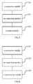
- Fig. 5 is a block diagram illustrating a device for power charging according to another exemplary embodiment.
- the device may include a connection module 501, an acquisition module 502 and a control module 503.
- the connection module 501 is configured to establish a connection of a first electronic device with a second electronic device.
- the acquisition module 502 is configured to acquire, based on the connection, real-time charged voltage information of the first electronic device, wherein the real-time charged voltage information varies with charged state of the first electronic device.
- the control module 503 is configured to control, during charging the first electronic device, the device to output a charging voltage to the first electronic device according to the real-time charged voltage information of the first electronic device to charge the first electronic device.
- connection module is further configured to establish the connection of the first electronic device with the second electronic device by using designated interfaces provided respectively on the first electronic device and the second electronic device and a designated type of data line between the first electronic device and the second electronic device.
- both the first electronic device and the second electronic device may be mobile terminals, or the first electronic device may be a mobile terminal and the second electronic device may be a mobile power supply device.
- Fig. 6 is a block diagram illustrating a device for power charging according to an exemplary embodiment.
- the device may include a connection module 601, an acquisition module 602 and a transmission module 603.
- the connection module 601 is configured to establish a connection of a first electronic device with a second electronic device.
- the acquisition module 602 is configured to detect in real time charged state of the first electronic device and acquire real-time charged voltage information of the first electronic device during the first electronic device being charged by the second electronic device, wherein the real-time charged voltage information varies with the charged state of the first electronic device.
- the transmission module 603 is configured to transmit in real time, based on the connection, the real-time charged voltage information of the first electronic device to the second electronic device such that the second electronic device controls a charging voltage outputted from the second electronic device to charge the first electronic device.
- connection module is further configured to establish the connection of the first electronic device with the second electronic device by using designated interfaces provided respectively on the first electronic device and the second electronic device and a designated type of data line between the first electronic device and the second electronic device.
- the acquisition module is further configured to acquire a preset current value multiplied by a present equivalent resistance of a battery as the real-time charged voltage information of the first electronic device when the charged state indicates that a present voltage value of the battery is smaller than a preset value, wherein the equivalent resistance of the battery varies with the charged state of the first electronic device, and acquire a preset voltage value as the real-time charged voltage information of the first electronic device when the charged state indicates that a present voltage value of the battery is greater than a preset value.
- Fig. 7 is a block diagram illustrating an electronic device 700 according to an exemplary embodiment.
- the device 700 may be a mobile phone, a computer, a digital broadcast terminal, a messaging device, a gaming console, a tablet, a medical device, an exercise equipment, a personal digital assistant, and the like.
- the devicde 700 may include one or more of the following components: a processing component 702, a memory 704, a power component 706, a multimedia component 708, an audio component 710, an input/output (I/O) interface 712, a sensor component 714, and a communication component 716.
- the processing component 702 typically controls overall operations of the device 700, such as the operations associated with display, telephone calls, data communications, camera operations, and recording operations.
- the processing component 702 may include one or more processors 720 to execute instructions to perform all or part of the steps in the above described methods.
- the processing component 702 may include one or more modules which facilitate the interaction between the processing component 702 and other components.
- the processing component 702 may include a multimedia module to facilitate the interaction between the multimedia component 708 and the processing component 702.
- the memory 704 is configured to store various types of data to support the operation of the device 700. Examples of such data include instructions for any applications or methods operated on the device 700, contact data, phonebook data, messages, pictures, video, etc.
- the memory 704 may be implemented using any type of volatile or non-volatile memory devices, or a combination thereof, such as a static random access memory (SRAM), an electrically erasable programmable read-only memory (EEPROM), an erasable programmable read-only memory (EPROM), a programmable read-only memory (PROM), a read-only memory (ROM), a magnetic memory, a flash memory, a magnetic or optical disk.
- SRAM static random access memory
- EEPROM electrically erasable programmable read-only memory
- EPROM erasable programmable read-only memory
- PROM programmable read-only memory
- ROM read-only memory
- magnetic memory a magnetic memory
- flash memory a flash memory
- magnetic or optical disk a magnetic or optical
- the power component 706 provides power to various components of the device 700.
- the power component 706 may include a power management system, one or more power sources, and any other components associated with the generation, management, and distribution of power for the device 700.
- the multimedia component 708 includes a screen providing an output interface between the device 700 and the user.
- the screen may include a liquid crystal display (LCD) and a touch panel (TP). If the screen includes the touch panel, the screen may be implemented as a touch screen to receive input signals from the user.
- the touch panel includes one or more touch sensors to sense touches, swipes, and gestures on the touch panel. The touch sensors may not only sense a boundary of a touch or swipe action, but also sense a period of time and a pressure associated with the touch or swipe action.
- the multimedia component 708 includes a front camera and/or a rear camera.
- the front camera and the rear camera may receive an external multimedia datum while the device 700 is in an operation mode, such as a photographing mode or a video mode.
- an operation mode such as a photographing mode or a video mode.
- Each of the front camera and the rear camera may be a fixed optical lens system or have optical focusing and zooming capability.
- the audio component 710 is configured to output and/or input audio signals.
- the audio component 710 includes a microphone ("MIC") configured to receive an external audio signal when the device 700 is in an operation mode, such as a call mode, a recording mode, and a voice recognition mode.
- the received audio signal may be further stored in the memory 704 or transmitted via the communication component 716.
- the audio component 710 further includes a speaker to output audio signals.
- the I/O interface 712 provides an interface between the processing component 702 and peripheral interface modules, the peripheral interface modules being, for example, a keyboard, a click wheel, buttons, and the like.
- the buttons may include, but are not limited to, a home button, a volume button, a starting button, and a locking button.
- the sensor component 714 includes one or more sensors to provide status assessments of various aspects of the device 700. For instance, the sensor component 714 may detect an open/closed status of the device 700, relative positioning of components (e.g., the display and the keypad, of the device 700), a change in position of the device 700 or a component of the device 700, a presence or absence of user contact with the device 700, an orientation or an acceleration/deceleration of the device 700, and a change in temperature of the device 700.
- the sensor component 714 may include a proximity sensor configured to detect the presence of a nearby object without any physical contact.
- the sensor component 714 may also include a light sensor, such as a CMOS or CCD image sensor, for use in imaging applications.
- the sensor component 714 may also include an accelerometer sensor, a gyroscope sensor, a magnetic sensor, a pressure sensor, or a temperature sensor.
- the communication component 716 is configured to facilitate communication, wired or wirelessly, between the device 700 and other devices.
- the device 700 can access a wireless network based on a communication standard, such as WiFi, 2G, or 3G, or a combination thereof.
- the communication component 716 receives a broadcast signal or broadcast associated information from an external broadcast management system via a broadcast channel.
- the communication component 716 further includes a near field communication (NFC) module to facilitate short-range communications.
- the NFC module may be implemented based on a radio frequency identification (RFID) technology, an infrared data association (IrDA) technology, an ultra-wideband (UWB) technology, a Bluetooth (BT) technology, and other technologies.
- RFID radio frequency identification
- IrDA infrared data association
- UWB ultra-wideband
- BT Bluetooth
- the device 700 may be implemented with one or more application specific integrated circuits (ASICs), digital signal processors (DSPs), digital signal processing devices (DSPDs), programmable logic devices (PLDs), field programmable gate arrays (FPGAs), controllers, micro-controllers, microprocessors, or other electronic components, for performing the above described methods.
- ASICs application specific integrated circuits
- DSPs digital signal processors
- DSPDs digital signal processing devices
- PLDs programmable logic devices
- FPGAs field programmable gate arrays
- controllers micro-controllers, microprocessors, or other electronic components, for performing the above described methods.
- non-transitory computer-readable storage medium including instructions, such as included in the memory 704, executable by the processor 720 in the device 700, for performing the above-described methods.
- the non-transitory computer-readable storage medium may be a ROM, a RAM, a CD-ROM, a magnetic tape, a floppy disc, an optical data storage device, and the like.
- a non-transitory computer readable storage medium having stored therein instructions that, when executed by a processor of a terminal, cause the terminal to perform a method for power charging as described above.
Landscapes
- Engineering & Computer Science (AREA)
- Power Engineering (AREA)
- Manufacturing & Machinery (AREA)
- Chemical & Material Sciences (AREA)
- Chemical Kinetics & Catalysis (AREA)
- Electrochemistry (AREA)
- General Chemical & Material Sciences (AREA)
- Charge And Discharge Circuits For Batteries Or The Like (AREA)
- Secondary Cells (AREA)
- Telephone Function (AREA)
Applications Claiming Priority (1)
| Application Number | Priority Date | Filing Date | Title |
|---|---|---|---|
| CN201510446546.4A CN106410303B (zh) | 2015-07-27 | 2015-07-27 | 充电方法及装置 |
Publications (2)
| Publication Number | Publication Date |
|---|---|
| EP3125400A2 true EP3125400A2 (fr) | 2017-02-01 |
| EP3125400A3 EP3125400A3 (fr) | 2017-03-01 |
Family
ID=56693949
Family Applications (1)
| Application Number | Title | Priority Date | Filing Date |
|---|---|---|---|
| EP16180426.5A Pending EP3125400A3 (fr) | 2015-07-27 | 2016-07-20 | Procédé et dispositif de charge d'alimentation |
Country Status (8)
| Country | Link |
|---|---|
| US (1) | US10116157B2 (fr) |
| EP (1) | EP3125400A3 (fr) |
| JP (1) | JP2017534241A (fr) |
| KR (1) | KR20170023760A (fr) |
| CN (1) | CN106410303B (fr) |
| MX (1) | MX367463B (fr) |
| RU (1) | RU2635661C2 (fr) |
| WO (1) | WO2017016163A1 (fr) |
Cited By (3)
| Publication number | Priority date | Publication date | Assignee | Title |
|---|---|---|---|---|
| WO2018151860A1 (fr) * | 2017-02-17 | 2018-08-23 | Qualcomm Incorporated | Charge de batterie basée sur une distribution de puissance de bus série universel (usb pd) |
| KR20190120802A (ko) * | 2017-03-13 | 2019-10-24 | 니뽄 다바코 산교 가부시키가이샤 | 흡연 시스템, 급전 제어 방법, 프로그램, 일차 장치, 및 이차 장치 |
| JP2020058394A (ja) * | 2020-01-23 | 2020-04-16 | 日本たばこ産業株式会社 | 喫煙システム、給電制御方法、プログラム、一次装置、及び二次装置 |
Families Citing this family (21)
| Publication number | Priority date | Publication date | Assignee | Title |
|---|---|---|---|---|
| KR101898185B1 (ko) * | 2014-11-11 | 2018-09-12 | 광동 오포 모바일 텔레커뮤니케이션즈 코포레이션 리미티드 | 전원 어댑터, 단말기 및 충전 시스템 |
| US20170244265A1 (en) * | 2014-11-11 | 2017-08-24 | Guangdong Oppo Mobile Telecommunications Corp., Ltd. | Communication method, power adaptor and terminal |
| US10587135B2 (en) * | 2015-09-11 | 2020-03-10 | Microsoft Technology Licensing, Llc | Adaptive battery charging |
| WO2018038423A1 (fr) * | 2016-08-23 | 2018-03-01 | 삼성전자 주식회사 | Appareil d'alimentation électrique, dispositif électronique recevant de l'énergie, et son procédé de commande |
| TWI625915B (zh) * | 2016-11-18 | 2018-06-01 | Industrial Technology Research Institute | 智慧型充電方法 |
| KR102331070B1 (ko) * | 2017-02-03 | 2021-11-25 | 삼성에스디아이 주식회사 | 배터리 팩 및 배터리 팩의 충전 제어 방법 |
| US20180254648A1 (en) * | 2017-03-01 | 2018-09-06 | Dialog Semiconductor (Uk) Limited | Applying Alternate Modes of USB Type-C for Fast Charging Systems |
| CN106685018B (zh) * | 2017-03-17 | 2020-06-23 | 赣州市瑞嘉达电子有限公司 | 一种反向充电方法、装置及终端 |
| AU2018249241B2 (en) | 2017-04-07 | 2020-07-16 | Guangdong Oppo Mobile Telecommunications Corp., Ltd. | Wireless charging apparatus, device to be charged and control method therefor |
| US20200321794A1 (en) * | 2017-12-08 | 2020-10-08 | Hewlett-Packard Development Company, L.P. | Battery charge controls |
| CN108859803A (zh) * | 2018-04-27 | 2018-11-23 | 北海和思科技有限公司 | 一种电动车充电器智能控制系统及其控制方法 |
| EP3709472A4 (fr) * | 2018-09-06 | 2021-02-17 | Guangdong Oppo Mobile Telecommunications Corp., Ltd. | Procédé de régulation de charge, terminal et support de stockage informatique |
| CN109768602B (zh) * | 2018-10-11 | 2021-11-09 | 浙江动一新能源动力科技股份有限公司 | 一种园林工具的电池包充放电方法及系统 |
| CN112444599B (zh) * | 2019-08-28 | 2023-09-19 | 北京小米移动软件有限公司 | 电池破损检测方法及装置 |
| CN112564294B (zh) * | 2019-09-24 | 2023-08-29 | 北京小米移动软件有限公司 | 充电方法、装置及存储介质 |
| CN110824372A (zh) * | 2019-11-25 | 2020-02-21 | Oppo广东移动通信有限公司 | 一种判断电池内短路的方法、设备和电子设备 |
| US11233417B2 (en) * | 2020-01-02 | 2022-01-25 | Sennheiser Electronic Gmbh & Co. Kg | Rechargeable charger for rechargeable devices, and method for charging rechargeable devices |
| WO2022061542A1 (fr) * | 2020-09-22 | 2022-03-31 | 深圳市大疆创新科技有限公司 | Procédé de commande d'alimentation électrique, dispositif de traitement d'image, dispositif de commande de photographie et support de stockage |
| JP7554500B2 (ja) * | 2020-12-22 | 2024-09-20 | TeraWatt Technology株式会社 | 電池システム、充電装置及び充電方法 |
| EP4340166B1 (fr) * | 2021-07-27 | 2025-10-15 | Samsung Electronics Co., Ltd. | Appareil électronique pour charger un autre appareil électronique, et procédé de commande d'appareil électronique pour charger un autre appareil électronique |
| CN119278425A (zh) | 2022-07-27 | 2025-01-07 | 雷蛇(亚太)私人有限公司 | 输入设备 |
Citations (1)
| Publication number | Priority date | Publication date | Assignee | Title |
|---|---|---|---|---|
| CN104485724A (zh) * | 2014-12-31 | 2015-04-01 | 展讯通信(上海)有限公司 | 待充电设备的充电方法、装置、待充电设备及充电系统 |
Family Cites Families (19)
| Publication number | Priority date | Publication date | Assignee | Title |
|---|---|---|---|---|
| CN101150327A (zh) * | 2006-09-22 | 2008-03-26 | 鸿富锦精密工业(深圳)有限公司 | 便携式设备借电系统及便携式设备 |
| JP2008204800A (ja) * | 2007-02-20 | 2008-09-04 | Matsushita Electric Ind Co Ltd | 非水系電解質二次電池の急速充電方法およびそれを用いる電子機器 |
| US7701168B2 (en) * | 2007-03-23 | 2010-04-20 | Sony Ericsson Mobile Communications Ab | Universal serial bus charger device |
| JP4966998B2 (ja) * | 2009-06-18 | 2012-07-04 | パナソニック株式会社 | 充電制御回路、電池パック、及び充電システム |
| CN102025001B (zh) * | 2009-09-21 | 2013-07-31 | 联想(北京)有限公司 | 一种终端的充电、供电方法及终端 |
| WO2011156768A2 (fr) | 2010-06-11 | 2011-12-15 | Mojo Mobility, Inc. | Système de transfert d'énergie sans fil prenant en charge l'interopérabilité et aimants multipolaires à utiliser avec ce système |
| EP2579423B8 (fr) * | 2011-10-05 | 2023-08-23 | Malikie Innovations Limited | Charge et communication sans fil avec des dispositifs d'alimentation et dispositifs d'alimentation dans un système de communication |
| US9287731B2 (en) | 2012-02-29 | 2016-03-15 | Fairchild Semiconductor Corporation | Battery charging system including current observer circuitry to avoid battery voltage overshoot based on battery current draw |
| EP2701268A1 (fr) * | 2012-08-24 | 2014-02-26 | Philip Morris Products S.A. | Système électronique portable comprenant un dispositif de charge et procédé de chargement d'une batterie secondaire |
| US9431839B2 (en) | 2012-10-26 | 2016-08-30 | Nokia Technologies Oy | Method, apparatus, and computer program product for optimized device-to-device charging |
| CN103928947B (zh) * | 2013-01-10 | 2016-10-05 | 联想(北京)有限公司 | 电子设备的充电方法、装置及系统 |
| CN104701918B (zh) * | 2013-12-10 | 2017-06-30 | 南京德朔实业有限公司 | 一种充电组合及其控制方法 |
| CN103701182A (zh) * | 2013-12-16 | 2014-04-02 | 小米科技有限责任公司 | 充电器、电子设备及充电系统 |
| CN103762702B (zh) * | 2014-01-28 | 2015-12-16 | 广东欧珀移动通信有限公司 | 电子设备充电装置及其电源适配器 |
| CN103762690B (zh) * | 2014-01-28 | 2016-08-24 | 广东欧珀移动通信有限公司 | 充电系统 |
| CN104135053A (zh) * | 2014-08-06 | 2014-11-05 | 中国联合网络通信集团有限公司 | 电量共享方法和装置 |
| CN104467116B (zh) * | 2014-12-31 | 2018-03-23 | 展讯通信(上海)有限公司 | 充电方法、装置以及充电器 |
| CN104659881B (zh) * | 2015-03-06 | 2017-04-19 | 广东欧珀移动通信有限公司 | 移动终端的充电方法及装置 |
| US20160378155A1 (en) * | 2015-06-26 | 2016-12-29 | Microsoft Technology Licensing, Llc | Charge process in usb setup |
-
2015
- 2015-07-27 CN CN201510446546.4A patent/CN106410303B/zh active Active
- 2015-12-25 KR KR1020167004900A patent/KR20170023760A/ko not_active Ceased
- 2015-12-25 WO PCT/CN2015/098957 patent/WO2017016163A1/fr not_active Ceased
- 2015-12-25 MX MX2016003722A patent/MX367463B/es active IP Right Grant
- 2015-12-25 RU RU2016110908A patent/RU2635661C2/ru active
- 2015-12-25 JP JP2017530398A patent/JP2017534241A/ja active Pending
-
2016
- 2016-07-18 US US15/212,852 patent/US10116157B2/en active Active
- 2016-07-20 EP EP16180426.5A patent/EP3125400A3/fr active Pending
Patent Citations (1)
| Publication number | Priority date | Publication date | Assignee | Title |
|---|---|---|---|---|
| CN104485724A (zh) * | 2014-12-31 | 2015-04-01 | 展讯通信(上海)有限公司 | 待充电设备的充电方法、装置、待充电设备及充电系统 |
Cited By (9)
| Publication number | Priority date | Publication date | Assignee | Title |
|---|---|---|---|---|
| WO2018151860A1 (fr) * | 2017-02-17 | 2018-08-23 | Qualcomm Incorporated | Charge de batterie basée sur une distribution de puissance de bus série universel (usb pd) |
| KR20190120802A (ko) * | 2017-03-13 | 2019-10-24 | 니뽄 다바코 산교 가부시키가이샤 | 흡연 시스템, 급전 제어 방법, 프로그램, 일차 장치, 및 이차 장치 |
| EP3586656A4 (fr) * | 2017-03-13 | 2020-11-04 | Japan Tobacco Inc. | Système à fumer, procédé de commande d'alimentation électrique, programme, dispositif primaire et dispositif secondaire |
| US11445760B2 (en) | 2017-03-13 | 2022-09-20 | Japan Tobacco Inc. | Smoking system, power supply control method, program, primary device, and secondary device |
| US11918049B2 (en) | 2017-03-13 | 2024-03-05 | Japan Tobacco Inc. | Smoking system, power supply control method, program, primary device, and secondary device |
| EP4593242A3 (fr) * | 2017-03-13 | 2026-02-11 | Japan Tobacco Inc. | Système à fumer, procédé de commande d'alimentation électrique, programme, dispositif primaire et dispositif secondaire |
| JP2020058394A (ja) * | 2020-01-23 | 2020-04-16 | 日本たばこ産業株式会社 | 喫煙システム、給電制御方法、プログラム、一次装置、及び二次装置 |
| JP2024114869A (ja) * | 2020-01-23 | 2024-08-23 | 日本たばこ産業株式会社 | 喫煙システム、給電制御方法、プログラム、一次装置、及び二次装置 |
| JP7824360B2 (ja) | 2020-01-23 | 2026-03-04 | 日本たばこ産業株式会社 | 喫煙システム、給電制御方法、プログラム、一次装置、及び二次装置 |
Also Published As
| Publication number | Publication date |
|---|---|
| RU2016110908A (ru) | 2017-09-28 |
| CN106410303A (zh) | 2017-02-15 |
| EP3125400A3 (fr) | 2017-03-01 |
| MX367463B (es) | 2019-08-22 |
| KR20170023760A (ko) | 2017-03-06 |
| CN106410303B (zh) | 2019-02-19 |
| US10116157B2 (en) | 2018-10-30 |
| MX2016003722A (es) | 2017-12-07 |
| WO2017016163A1 (fr) | 2017-02-02 |
| RU2635661C2 (ru) | 2017-11-15 |
| JP2017534241A (ja) | 2017-11-16 |
| US20170033582A1 (en) | 2017-02-02 |
Similar Documents
| Publication | Publication Date | Title |
|---|---|---|
| EP3125400A2 (fr) | Procédé et dispositif de charge d'alimentation | |
| US10205332B2 (en) | Efficient two way charging method using master and slave devices | |
| EP2940523B1 (fr) | Procédé et dispositif permettant de configurer des paramètres photographiques | |
| EP3832841A1 (fr) | Circuit de recharge, dispositif électronique, procédé et dispositif de commande de recharge | |
| CN108574123B (zh) | 电池充电控制方法、装置及电池 | |
| EP3780328B1 (fr) | Dispositif de charge inversée | |
| EP3439138A1 (fr) | Procédé et terminal de chargement sans fil | |
| US10852798B2 (en) | Power supply control method and apparatus for power strip, and storage medium | |
| CN106067571A (zh) | 为电池充电的方法及电子设备 | |
| CN112421702A (zh) | 锂电池充电方法及装置 | |
| CN104577235B (zh) | 为便携式设备充电的方法、控制充电的方法、装置及系统 | |
| CN107124012B (zh) | 充电方法、装置、充电器、终端和系统 | |
| CN107546873A (zh) | 无线充电距离的控制方法及装置、电子设备 | |
| EP3828716A1 (fr) | Procédé et appareil d'identification de dispositif électronique, dispositif terminal et dispositif électronique | |
| CN106856339A (zh) | 充电方法、装置及电子设备 | |
| CN106026232A (zh) | Usb端口类型的检测方法及装置 | |
| CN105449764B (zh) | 充电方法、装置及系统 | |
| EP4050751A1 (fr) | Procédé, appareil et support d'enregistrement pour déterminer la durée de charge de batterie | |
| CN112886650B (zh) | 充电控制方法、装置及存储介质 | |
| CN113922457A (zh) | 充电方法、装置、电子设备及存储介质 | |
| CN116780672A (zh) | 充电方法及装置、电子设备、存储介质 | |
| CN109450032B (zh) | 无线充电的处理方法、装置及设备 | |
| EP3787143A1 (fr) | Procédé de charge et dispositif pour terminal mobile, terminal et support d'enregistrement | |
| CN113078697A (zh) | 充电控制方法及装置、转接器 | |
| CN115118805B (zh) | 一种测试设备、方法、装置及存储介质 |
Legal Events
| Date | Code | Title | Description |
|---|---|---|---|
| PUAI | Public reference made under article 153(3) epc to a published international application that has entered the european phase |
Free format text: ORIGINAL CODE: 0009012 |
|
| STAA | Information on the status of an ep patent application or granted ep patent |
Free format text: STATUS: THE APPLICATION HAS BEEN PUBLISHED |
|
| PUAL | Search report despatched |
Free format text: ORIGINAL CODE: 0009013 |
|
| AK | Designated contracting states |
Kind code of ref document: A2 Designated state(s): AL AT BE BG CH CY CZ DE DK EE ES FI FR GB GR HR HU IE IS IT LI LT LU LV MC MK MT NL NO PL PT RO RS SE SI SK SM TR |
|
| AX | Request for extension of the european patent |
Extension state: BA ME |
|
| AK | Designated contracting states |
Kind code of ref document: A3 Designated state(s): AL AT BE BG CH CY CZ DE DK EE ES FI FR GB GR HR HU IE IS IT LI LT LU LV MC MK MT NL NO PL PT RO RS SE SI SK SM TR |
|
| AX | Request for extension of the european patent |
Extension state: BA ME |
|
| RIC1 | Information provided on ipc code assigned before grant |
Ipc: H02J 7/00 20060101AFI20170124BHEP Ipc: H01M 10/44 20060101ALI20170124BHEP |
|
| STAA | Information on the status of an ep patent application or granted ep patent |
Free format text: STATUS: REQUEST FOR EXAMINATION WAS MADE |
|
| 17P | Request for examination filed |
Effective date: 20170831 |
|
| RBV | Designated contracting states (corrected) |
Designated state(s): AL AT BE BG CH CY CZ DE DK EE ES FI FR GB GR HR HU IE IS IT LI LT LU LV MC MK MT NL NO PL PT RO RS SE SI SK SM TR |
|
| STAA | Information on the status of an ep patent application or granted ep patent |
Free format text: STATUS: EXAMINATION IS IN PROGRESS |
|
| 17Q | First examination report despatched |
Effective date: 20171208 |