EP3125415B1 - Supraleitender radialspalt-synchronmaschine, magnetisierungsvorrichtung und magnetisierungsverfahren - Google Patents
Supraleitender radialspalt-synchronmaschine, magnetisierungsvorrichtung und magnetisierungsverfahren Download PDFInfo
- Publication number
- EP3125415B1 EP3125415B1 EP15769533.9A EP15769533A EP3125415B1 EP 3125415 B1 EP3125415 B1 EP 3125415B1 EP 15769533 A EP15769533 A EP 15769533A EP 3125415 B1 EP3125415 B1 EP 3125415B1
- Authority
- EP
- European Patent Office
- Prior art keywords
- wall portion
- superconductor
- rotor
- synchronous machine
- end part
- Prior art date
- Legal status (The legal status is an assumption and is not a legal conclusion. Google has not performed a legal analysis and makes no representation as to the accuracy of the status listed.)
- Active
Links
Images




Classifications
-
- H—ELECTRICITY
- H02—GENERATION; CONVERSION OR DISTRIBUTION OF ELECTRIC POWER
- H02K—DYNAMO-ELECTRIC MACHINES
- H02K21/00—Synchronous motors having permanent magnets; Synchronous generators having permanent magnets
- H02K21/12—Synchronous motors having permanent magnets; Synchronous generators having permanent magnets with stationary armatures and rotating magnets
- H02K21/14—Synchronous motors having permanent magnets; Synchronous generators having permanent magnets with stationary armatures and rotating magnets with magnets rotating within the armatures
-
- H—ELECTRICITY
- H02—GENERATION; CONVERSION OR DISTRIBUTION OF ELECTRIC POWER
- H02K—DYNAMO-ELECTRIC MACHINES
- H02K15/00—Processes or apparatus specially adapted for manufacturing, assembling, maintaining or repairing of dynamo-electric machines
- H02K15/02—Processes or apparatus specially adapted for manufacturing, assembling, maintaining or repairing of dynamo-electric machines of stator or rotor bodies
- H02K15/03—Processes or apparatus specially adapted for manufacturing, assembling, maintaining or repairing of dynamo-electric machines of stator or rotor bodies having permanent magnets
-
- H—ELECTRICITY
- H01—ELECTRIC ELEMENTS
- H01F—MAGNETS; INDUCTANCES; TRANSFORMERS; SELECTION OF MATERIALS FOR THEIR MAGNETIC PROPERTIES
- H01F13/00—Apparatus or processes for magnetising or demagnetising
- H01F13/003—Methods and devices for magnetising permanent magnets
-
- H—ELECTRICITY
- H01—ELECTRIC ELEMENTS
- H01F—MAGNETS; INDUCTANCES; TRANSFORMERS; SELECTION OF MATERIALS FOR THEIR MAGNETIC PROPERTIES
- H01F6/00—Superconducting magnets; Superconducting coils
-
- H—ELECTRICITY
- H02—GENERATION; CONVERSION OR DISTRIBUTION OF ELECTRIC POWER
- H02K—DYNAMO-ELECTRIC MACHINES
- H02K1/00—Details of the magnetic circuit
- H02K1/02—Details of the magnetic circuit characterised by the magnetic material
-
- H—ELECTRICITY
- H02—GENERATION; CONVERSION OR DISTRIBUTION OF ELECTRIC POWER
- H02K—DYNAMO-ELECTRIC MACHINES
- H02K1/00—Details of the magnetic circuit
- H02K1/06—Details of the magnetic circuit characterised by the shape, form or construction
- H02K1/22—Rotating parts of the magnetic circuit
- H02K1/27—Rotor cores with permanent magnets
- H02K1/2793—Rotors axially facing stators
- H02K1/2795—Rotors axially facing stators the rotor consisting of two or more circumferentially positioned magnets
- H02K1/2796—Rotors axially facing stators the rotor consisting of two or more circumferentially positioned magnets where both axial sides of the rotor face a stator
-
- H—ELECTRICITY
- H02—GENERATION; CONVERSION OR DISTRIBUTION OF ELECTRIC POWER
- H02K—DYNAMO-ELECTRIC MACHINES
- H02K55/00—Dynamo-electric machines having windings operating at cryogenic temperatures
- H02K55/02—Dynamo-electric machines having windings operating at cryogenic temperatures of the synchronous type
- H02K55/04—Dynamo-electric machines having windings operating at cryogenic temperatures of the synchronous type with rotating field windings
-
- Y—GENERAL TAGGING OF NEW TECHNOLOGICAL DEVELOPMENTS; GENERAL TAGGING OF CROSS-SECTIONAL TECHNOLOGIES SPANNING OVER SEVERAL SECTIONS OF THE IPC; TECHNICAL SUBJECTS COVERED BY FORMER USPC CROSS-REFERENCE ART COLLECTIONS [XRACs] AND DIGESTS
- Y02—TECHNOLOGIES OR APPLICATIONS FOR MITIGATION OR ADAPTATION AGAINST CLIMATE CHANGE
- Y02E—REDUCTION OF GREENHOUSE GAS [GHG] EMISSIONS, RELATED TO ENERGY GENERATION, TRANSMISSION OR DISTRIBUTION
- Y02E40/00—Technologies for an efficient electrical power generation, transmission or distribution
- Y02E40/60—Superconducting electric elements or equipment; Power systems integrating superconducting elements or equipment
Definitions
- the present invention relates to a radial-gap type superconducting synchronous machine, a magnetizing apparatus and a magnetizing method, and more particularly to a technique for effectively increasing captured magnetic flux in an object to be magnetized while ensuring the practical utility.
- Superconducting synchronous machines which use a superconducting material for a field system or an armature, have attracted attention e.g. for the reason that a high power output can be obtained with high efficiency, and studies and proposals have been made thereon.
- superconducting synchronous machine can be classified broadly into a radial-gap type and an axial-gap type.
- Patent document 1 Japanese Patent No.
- a superconducting synchronous machine of the radial-gap type (hereinafter referred to as a radial-gap type superconducting synchronous machine), and patent document 2 (Japanese Patent Laid-Open Publication No. 2004-235625 ) by the present inventors, for example, discloses a superconducting synchronous machine of the axial-gap type (hereinafter referred to as an axial-gap type superconducting synchronous machine).
- AU 2012289033 discloses an electric rotary machine.
- JP 2003 332128 discloses a magnetizing apparatus Yudong Jiang etal., "Magnetization Process of an HTS Motor and the Torque Ripple Suppression", IEEE TRANSACTIONS ON APPLIED SUPERCONDUCTIVITY, IEEE Service Center, Los Alamitos, CA, US, vol. 19, no. 3, 2009-06-01 , discloses a radial-gap type superconducting machine and a magnetizing apparatus.
- the radial-gap type superconducting synchronous machine of patent document 1 is a rotating field system-type synchronous machine in which a field system portion of a rotor is comprised of a permanent magnet, and an armature coil, provided in an armature as a stator, is comprised of a superconducting coil made of a superconducting material.
- the axial-gap type superconducting synchronous machine of patent document 2 has rotors and stators arranged alternately in the rotational axis direction of the rotors (a stator, a rotor and a stator are arranged in this order in an illustrated embodiment).
- the field system portion of the rotor is composed of a bulk superconductor.
- a bulk superconductor which is a mass of superconductor crystals, can capture magnetic flux lines at pinning points therein when a magnetic field (magnetic flux) is introduced into the bulk superconductor at a temperature which is not more than a critical temperature at which the matrix superconductor shows a superconducting transition.
- This enables the bulk superconductor to act as a magnet having a higher magnetic flux density than a permanent magnet.
- a field system portion having a high magnetic flux density can be obtained by allowing the bulk superconductor to capture magnetic flux lines, whereby a high power output can be obtained with high efficiency.
- the bulk superconductor can hold a stronger magnetic field than a superconducting coil provided that the superconducting coil has the same size as the bulk superconductor.
- the synchronous machine therefore has an advantage in terms of downsizing over a synchronous machine which uses a superconducting coil. Furthermore, the synchronous machine does not require connecting wiring for supplying electric current to the field system portion. The synchronous machine therefore has advantages also in terms of simplification of the device structure and enhancement in the efficiency of the device system, such as reduction in the amount of incoming heat.
- the axial-gap type superconducting synchronous machine of patent document 2 also has an advantage in that an armature coil, provided in an armature as a stator, is configured to function also as a magnetizing coil (magnetizing apparatus) for the bulk superconductor.
- the magnetizing apparatus is integrated with the synchronous machine. This makes it possible to magnetize the bulk superconductor conveniently in a timely manner.
- the axial-gap type superconducting synchronous machine of patent document 2 in performing its magnetization with the armature coil, uses pulse magnetization in order to prevent the magnetizing apparatus from becoming large-sized upon the integration of the magnetizing apparatus with the synchronous machine and thereby losing the practical utility.
- a superconductor may be magnetized by pulse magnetization or static magnetic field magnetization.
- pulse magnetization a strong magnetic field is instantaneously applied to a bulk superconductor, which is held at a temperature lower than its superconducting critical temperature, to introduce magnetic flux into the bulk superconductor.
- the bulk superconductor is allowed to capture the magnetic flux by the pinning effect, so that the bulk superconductor will function as a magnet having a high magnetic flux density.
- a static magnetic field (stationary magnetic field) is applied to a bulk superconductor, which is held at a temperature higher than its superconducting critical temperature, to introduce magnetic flux into the bulk superconductor.
- the temperature of the bulk superconductor is then lowered to a temperature lower than the superconducting critical temperature, and the bulk superconductor is held at that temperature to allow the bulk superconductor to capture the magnetic flux by the pinning effect, thereby allowing the bulk superconductor to function as a magnet having a high magnetic flux density.
- an object to be magnetized such as a bulk superconductor, can capture more magnetic flux lines by static magnetic field magnetization than by pulse magnetization.
- a large-scale magnetizing apparatus using a superconducting coil will be needed as described above. Since the size of the entire synchronous machine should thus be increased, this attempt is not always desirable in the light of practical utility.
- a coil is generally disposed such that it surrounds the periphery of an object to be magnetized. If in the synchronous machine of patent document 2 a coil is disposed such that it surrounds the bulk superconductor provided in the rotor, the rotor will increase in size excessively and wiring will become complicated, whereby the practical utility will be lost.
- the present inventors have made intensive studies on a technique which uses static magnetic field magnetization and yet ensures practical utility, and which can secure a lot of captured magnetic flux in a field system portion of a superconducting synchronous machine. It has now been found that by devising the construction of a field system portion of a superconducting synchronous machine or the construction of a magnetizing apparatus, the amount of captured magnetic flux in an object to be magnetized can be effectively increased while ensuring the practical utility. The finding led to the present invention.
- the present invention has been made in view of the above situation. It is therefore an object of the present invention to provide a radial-gap type superconducting synchronous machine, a magnetizing apparatus and a magnetizing method which can effectively increase captured magnetic flux in an object to be magnetized while ensuring the practical utility.
- the superconductor is disposed in plural numbers at the distal end part of the magnetic pole, and the plurality of superconductors are disposed in such a stepped arrangement that when viewed in the direction of the rotational axis of the rotor, a superconductor closest to the center of the magnetic pole is located nearer to the stator than the other superconductors.
- the superconductor preferably has a rectangular shape as viewed from outside in the radial direction of the rotor.
- the superconductor is disposed in plural numbers at the distal end part of the magnetic pole, and the plurality of superconductors are disposed at the distal end part of the magnetic pole such that they are arranged in the circumferential direction of the rotor, and that they are arranged in the direction of the rotational axis of the rotor.
- a magnetizing apparatus according to another aspect of the present disclosure is defined in claim 5.
- a magnetizing method according to another aspect of the present disclosure is defined in claim 6.
- step of performing magnetization application of static magnetic field to the superconductor may be started under conditions that the temperature of the superconductor is higher than its superconducting transition temperature and, after the magnetic flux density of the static magnetic field has reached a predetermined target value, the temperature of the superconductor may be lowered to a predetermined temperature lower than the superconducting transition temperature while keeping the magnetic flux density at the target value, and then the magnetic field applied by the magnetizing apparatus may be eliminated.
- the radial-gap type superconducting synchronous machine of the present invention when the superconductor disposed on the peripheral side of the rotor is magnetized by a magnetizing apparatus from outside in the radial direction of the rotor, a lot of magnetic flux lines from the magnetizing apparatus pass through the superconductor and are guided to the ferromagnet disposed on the rotational axis side of the superconductor. This enables concentrated magnetic flux lines to pass through the superconductor.
- the superconductor can be magnetized with high efficiency even when, for example, the coil of the magnetizing apparatus is disposed outside the superconductor in the radial direction of the rotor and at a distance from the superconductor, and the coil is not a large-sized one surrounding the superconductor.
- a sufficient captured magnetic flux can therefore be ensured in the superconductor even when magnetization is performed by a magnetizing apparatus which is not large-sized.
- captured magnetic flux in the superconductor can be effectively increased while ensuring the practical utility. This makes it possible to increase the torque and the power output of the synchronous machine.
- the magnetic pole center side of the superconductor when viewed in the direction of the rotational axis of the rotor, is disposed nearer to the stator than the magnetic pole end side.
- the superconductor is disposed such that it follows the arc-shaped inner surface of the stator. This can reduce the gap between the superconductor and the stator, thereby making it possible to allow a magnetic field from the superconductor to efficiently act on the stator.
- the magnetized superconductor is attracted by the magnetic force to a magnetic portion of the magnetizing apparatus while, at the same time, the superconductor is attracted to the ferromagnet located on the rotational axis side of the superconductor. This can prevent the superconductor from moving toward the magnetizing apparatus, thus enabling the superconductor to be held in the initial installation position.
- the superconductor is disposed in plural numbers at the distal end part of the magnetic pole, and the plurality of superconductors are disposed in such a stepped arrangement that when viewed in the direction of the rotational axis of the rotor, a superconductor closest to the center of the magnetic pole is located nearer to the stator than the other superconductors, the superconductor closest to the center of the magnetic pole can be easily disposed close to the stator.
- the superconductor In the case where the superconductor has a rectangular shape as viewed from outside in the radial direction of the rotor, the superconductor can efficiently capture magnetic flux lines, and the total amount of magnetic flux in the superconductor can be increased. This can increase the torque and the power output of the synchronous machine.
- the superconductor is disposed in plural numbers at the distal end part of the magnetic pole, and the plurality of superconductors are disposed such that they are arranged in the circumferential direction of the rotor, and that they are arranged in the direction of the rotational axis of the rotor, a wide magnetic flux capturing area can be ensured with ease. This can increase the total amount of magnetic flux in magnetic flux capturing area, thereby increasing the torque and the power output of the synchronous machine.
- the coil is covered by the top wall portion and the peripheral wall portion of the housing made of ferromagnetic material, and the peripheral wall portion opens in the opposite direction from the top wall portion.
- a magnetic circuit is therefore formed in which magnetic flux flows in the following order: one end part (distal end part) of the core portion ⁇ the peripheral wall portion ⁇ the top wall portion ⁇ the other end part (proximal end part) of the core portion, or in the following order: the other end part (proximal end part) of the core portion ⁇ the top wall portion ⁇ the peripheral wall portion ⁇ the one end part (distal end part) of the core portion.
- the magnetizing apparatus of the present invention sufficient captured magnetic flux can be ensured in an object to be magnetized even when the coil lies at a distance from the object.
- the degree of freedom of disposition that can ensure sufficient captured magnetic flux for the object can be enhanced.
- the practical utility can be ensured also in this respect.
- the magnetizing apparatus Even when the magnetizing apparatus is disposed in proximity to a magnetic pole, as an object to be magnetized, of e.g. a multi-pole rotor, the magnetizing apparatus can be prevented from interfering with the neighbor magnetic pole(s). Sufficient captured magnetic flux can therefore be ensured in each of the magnetic poles of the rotor.
- the peripheral wall portion is provided with the bottom wall portion made of a ferromagnetic material, extending from the distal end part of the peripheral wall portion toward the core portion and, when viewed in the direction in which the core portion vertically extends downward, extending to a position not overlapping the core portion, and the disposition space is formed in an area located opposite the distal end part of the core portion and located inside the inner periphery of the bottom wall portion, magnetic flux lines flow from the one end part (distal end part) of the core portion and reach the bottom wall portion, or flow from the bottom wall portion and reach the one end part (distal end part) of the core portion.
- the magnetic flux lines can therefore be made denser (more concentrated) on a line extending from the one end part of the core portion in the disposition space. This makes it possible to more effectively ensure a high magnetic flux density on the line extending from the one end part of the core portion in the disposition space, thereby further increasing the efficiency of magnetization of an object to be magnetized.
- the magnetizing method of the present invention which comprises preparing the radial-gap type superconducting synchronous machine in which the ferromagnet is disposed on the rotational axis side of the superconductor, and magnetizing the synchronous machine, when the superconductor disposed on the peripheral side of the rotor is magnetized by a magnetizing apparatus from outside in the radial direction of the rotor, a lot of magnetic flux lines from the magnetizing apparatus pass through the superconductor and are guided to the ferromagnet disposed on the rotational axis side of the superconductor. This enables concentrated magnetic flux lines to pass through the superconductor.
- the superconductor can be magnetized with high efficiency even when, for example, the coil of the magnetizing apparatus is disposed outside the superconductor in the radial direction of the rotor and at a distance from the superconductor, and the coil is not a large-sized one surrounding the superconductor.
- a sufficient captured magnetic flux can therefore be ensured in the superconductor even when magnetization is performed by a magnetizing apparatus which is not large-sized.
- captured magnetic flux in the superconductor can be effectively increased while ensuring the practical utility. This makes it possible to increase the torque and the power output of the synchronous machine.
- the magnetizing method of the present invention which comprises preparing the magnetizing apparatus including the coil housed in the housing made of a ferromagnetic material, and magnetizing the synchronous machine, the coil is covered by the top wall portion and the peripheral wall portion of the housing made of ferromagnetic material, and the peripheral wall portion opens in the opposite direction from the top wall portion.
- a magnetic circuit is therefore formed in which magnetic flux flows in the following order: one end part (distal end part) of the core portion ⁇ the peripheral wall portion ⁇ the top wall portion ⁇ the other end part (proximal end part) of the core portion, or in the following order: the other end part (proximal end part) of the core portion ⁇ the top wall portion ⁇ the peripheral wall portion ⁇ the one end part (distal end part) of the core portion.
- the magnetizing apparatus including the coil housed in the housing made of a ferromagnetic material
- sufficient captured magnetic flux can be ensured in an object to be magnetized even when the coil lies at a distance from the object.
- the degree of freedom of disposition that can ensure sufficient captured magnetic flux for the object can be enhanced.
- the practical utility can be ensured also in this respect.
- the magnetizing apparatus can be prevented from interfering with the neighbor magnetic pole(s). Sufficient captured magnetic flux can therefore be ensured in each of the magnetic poles of the rotor.
- High-efficiency magnetization of a superconductor can be performed effectively especially when the radial-gap type superconducting synchronous machine having the ferromagnet disposed on the rotational axis side of the superconductor is magnetized by means of the magnetizing apparatus including the coil housed in the housing made of a ferromagnetic material.
- the peripheral wall portion is provided with the bottom wall portion made of a ferromagnetic material, extending from the distal end part of the peripheral wall portion toward the core portion and, when viewed in the direction in which the core portion vertically extends downward, extending to a position not overlapping the core portion, and the disposition space is formed in an area located opposite the distal end part of the core portion and located inside the inner periphery of the bottom wall portion, the magnetizing apparatus is preferably disposed such that the superconductor in the disposition space of the magnetizing apparatus is located nearer to the core portion than the bottom wall portion. This enables effective magnetization of the superconductor with a high-density magnetic flux.
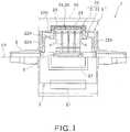
- FIG. 1 is a half cross-sectional side view of the radial-gap type superconducting synchronous machine 1.
- the radial-gap type superconducting synchronous machine 1 includes a stator 10 having a circular cross-sectional shape, shown by the two-dot chain lines in FIG. 1 , and a rotor 20 rotatably supported inside the stator 10.
- the radial-gap type superconducting synchronous machine 1 is a rotating field system-type synchronous machine; the stator 10 is provided with a not-shown armature coil, and the rotor 20 on the field system side is provided with magnetic poles 21.
- the rotor 20 is secured to a rotating shaft 2 extending on the rotational axis shown as C1 in FIG. 1 , so that the rotor 20 can rotate, together with the rotating shaft 2, on the rotational axis C1.
- a direction along the rotational axis C1 is hereinafter referred to as the rotational axis C1 direction, a direction perpendicular to the rotational axis C1 as the radial direction or radially, and a direction around the rotational axis C1 as the circumferential direction.
- FIG. 2 is a diagram of the radial-gap type superconducting synchronous machine 1 as viewed in the rotational axis C1 direction.
- the rotor 20 includes a rotor body 22 comprising a pair of disk portions 22A, secured to the rotating shaft 2 and extending in the radial direction, and a cylindrical drum portion 22B connecting the peripheries of the disks 22A, four convex magnetic poles 21 secured to the periphery of the drum portion 22B of the rotor body 22, and a generally-cylindrical vacuum cover 3 closed at both ends and hermetically covering the exteriors of the rotor body 22 and the magnetic poles 21.
- each magnetic pole fixing portion 22C is formed on the periphery of the drum portion 22B of the rotor body 22 at regular intervals in the circumferential direction.
- Each magnetic pole 21 is fixed to the distal end part of a corresponding one of the magnetic pole fixing portions 22C.
- the rotor body 22 of this embodiment is formed mainly of non-magnetic stainless steel.
- the rotor body 22 and the vacuum cover 3 are each secured integrally to the rotating shaft 2 so that the rotor body 22 and the vacuum cover 3 can rotate, together with the rotating shaft 2, on the rotational axis C1.
- the vacuum cover 3 is provided to form a vacuum insulating layer between it and the rotor body 22/the magnetic poles 21, thereby insulating the rotor 20 from the outside.
- the vacuum cover 3 of this embodiment is formed mainly of non-magnetic stainless steel; however, it may be formed of an aluminum alloy or the like.
- the vacuum cover 3, in the periphery, has convex projecting portions that cover the magnetic poles 21.
- FIG. 3 is a cross-sectional view taken along the line III-III of FIG. 2
- FIG. 4 is a cross-sectional view taken along the line IV-IV of FIG. 3
- the magnetic poles 21 of this embodiment each include a cooling base member 23 having a rectangular plate-like shape and secured to the magnetic pole fixing portion 22C of the rotor body 22, a bulk aggregate 24 consisting of a plurality of bulk superconductors 30, disposed radially outside the cooling base member 23 and located on the distal end part side of the magnetic pole 21, and a bulk fixing member 25 disposed radially outside the bulk aggregate 24 and which sandwiches and fixes the bulk aggregate 24 between it and the cooling base member 23.
- the cooling base members 23 of this embodiment are formed of OFHC (oxygen-free high conductivity) copper.
- an installation surface 23A for installation of the bulk superconductors 30 of the bulk aggregate 24 is formed in the radially outer surface of each cooling base member 23.
- the installation surface 23A when viewed in the rotational axis C1 direction, has a central portion 23C located centrally (in the center of the magnetic pole 21), and side portions 23S located on both sides of the central portion 23C.
- the central portion 23C projects radially outward (toward the stator 10) from the side portions 23S. Further, as shown in FIG. 3 , the central portion 23C and the side portions 23S extend parallel to the rotational axis C1 direction.
- connecting portions 23B projecting radially inward are formed on the radially inner surface of each cooling base member 23.
- a heat-transfer member 4 made of, for example, a copper material is connected to each connecting portion 23B.
- the heat-transfer members 4 extend radially inward from the connecting portions 23B, and are connected to a heat exchanger 5 installed in a portion, covered by the rotor 20, of the rotating shaft 2.
- the heat of the bulk aggregate 24 is transferred via the cooling base member 23 and the heat-transfer members 4 to the heat exchanger 5, and absorbed by the heat exchanger 5.
- the bulk superconductors 30 of the bulk aggregate 24, installed on the cooling base member 23, can thus be maintained at a low temperature (not more than their superconducting transition temperature).
- FIG. 5 is a perspective view of the bulk superconductors 30 constituting the bulk aggregate 24.
- the bulk superconductors 30 of the bulk aggregate 24 each have a rectangular shape as viewed from radially outside, and also have a rectangular shape in a radial cross-section.
- GdBCO GdBa 2 Cu 3 O 7-z
- GdBa 2 Cu 3 O 7-z which is a so-called high-temperature bulk superconducting material, is used as the bulk superconductors 30.
- bulk superconductors 30 are disposed in a 3 x 5 arrangement on the installation surface 23A of each cooling base member 23.
- one bulk superconductor 30 is disposed on each of the central portion 23C and the side portions 23S of the installation surface 23A of each cooling base member 23 such that the three bulk superconductors 30 are arranged in the circumferential direction of the rotational axis C1.
- the bulk superconductors 30 are disposed such that 5 bulk superconductors 30 are arranged in the rotational axis C1 direction on each of the central portion 23C and the two side portions 23S. Any two adjacent bulk superconductors 30 are disposed in contact with each other, and thus the bulk superconductors 30 are densely aggregated.
- the bulk aggregate 24 consisting of the bulk superconductors 30 arranged in such a manner, has a rectangular contour elongated in the rotational axis C1 direction.
- the central portion 23C of the installation surface 23A projects radially outward (toward the stator 10) from the side portions 23S. Therefore, when viewed in the rotational axis C1 direction, the bulk superconductors 30 are disposed in the stepped arrangement. Thus, when viewed in the rotational axis C1 direction, the bulk superconductor 30 closest to the center of each magnetic pole 21 is located nearer to the stator 10 than the other bulk superconductors 30.
- the bulk fixing member 25 is secured to the magnetic pole fixing portion 22C, and sandwiches the bulk aggregate 24 between it and the cooling base member 23 to hold the bulk superconductors 30 of the bulk aggregate 24.
- the bulk fixing member 25 of this embodiment is formed of a non-magnetic material.
- a ferromagnet 28 is disposed on the rotational axis C1 side of the thus-constructed magnetic pole 21 (the bulk aggregate 24). As shown in FIGS. 3 and 4 , the ferromagnet 28 is disposed in close proximity to the cooling base member 23 of the magnetic pole 21.
- the ferromagnet 28 of this embodiment is formed of a ferromagnetic metal material composed mainly of iron.
- FIG. 6 is a perspective view of the ferromagnet 28. As shown in FIG. 6 , the ferromagnet 28 has a rectangular plate-like shape and has through-holes 28A for passage of the above-described heat-transfer members 4 therethrough.
- the ferromagnet 28 is disposed in close proximity to the cooling base member 23, with the heat-transfer members 4 being inserted into the through-holes 28A, and is fixed to the magnetic pole fixing portion 22C.
- the ferromagnet 28 has a larger size than the bulk aggregate 24 when viewed in the radial direction, and is disposed such that it covers the entire bulk aggregate 24 from inside.
- the above-described radial-gap type superconducting synchronous machine 1 is subjected to magnetization of the bulk superconductors 30 of the bulk aggregate 24 with the below-described magnetizing apparatus 100.
- the ferromagnet 28 can guide magnetic flux lines from the magnetizing apparatus 100 so that they pass through the bulk aggregate 24 during the magnetization and, in addition, can stably keep the bulk aggregate 24 in the initial installation position after the magnetization of the bulk aggregate 24. The details will be described below.
- FIG. 7 is a perspective view of the magnetizing apparatus 100
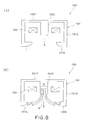
- FIG. 8(A) is a vertical cross-sectional view of the magnetizing apparatus 100
- FIG. 8(B) is a diagram illustrating part of magnetic flux lines generated by the magnetizing apparatus 100.
- the magnetizing apparatus 100 of this embodiment includes a housing 101 made of a ferromagnetic material, including a top wall portion 101T, a peripheral wall portion 101S vertically extending downward from a peripheral portion of the top wall portion 101T, and a core portion 101C located inside the peripheral wall portion 101S and vertically extending downward from the inner surface of the top wall portion 101T.
- the housing 101 is formed of a ferromagnetic metal material composed mainly of iron.
- the core portion 101C is located in an intermediate area between the opposing peripheral wall portions 101S.
- the peripheral wall portion 101S opens in the opposite direction from the top wall portion 101T.
- a superconducting coil (hereinafter referred to simply as coil) 102 wound around the core portion 101C and covered by the top wall portion 101T and the peripheral wall portion 101S.
- the coil 102 is formed of a superconducting material (Bi2233 (Bi 2 Sr 2 Ca 2 Cu 3 O 10+ ⁇ ) in this embodiment), and is connected to a current supply section 104 by a connecting wire 103 drawn out of the housing 101.
- a magnetic field is generated by the coil 102 by supplying an electric current from the current supply section 104 to the coil 102.
- the housing 101 has a generally-rectangular contour, and the core portion 101C has an elongated shape extending in the longitudinal direction of the housing 101.
- the length of the core portion 101C in the longitudinal direction is equal to the length of the bulk aggregate 24 of the radial-gap type superconducting synchronous machine 1 in the rotational axis C1 direction (see FIG. 3 ).
- the coil 102 which is wound around the core portion 101C, also has a generally-rectangular contour.
- the coil 102 is composed of generally-rectangular multi-layer wire windings.
- the height of the peripheral wall portion 101S from the top wall portion 101T is larger than the height of the core portion 101C from the top wall portion 101T.
- a bottom wall portion 101E extending from the distal end part of the peripheral wall portion 101S toward the core portion 101C, is formed integrally with the peripheral wall portion 101S.
- the bottom wall portion 101E, formed integrally with the peripheral wall portion 101S is also made of a ferromagnetic material.
- the bottom wall portion 101E when viewed in the direction in which the core portion 101C vertically extends (projects) downward, the bottom wall portion 101E extends to a position not overlapping the core portion 101C.
- a disposition space D for an object to be magnetized is formed in an area located inside the inner periphery of the bottom wall portion 101E and located opposite the distal end part of the core portion 101C in the direction in which the core portion 101C vertically extends (projects) downward.
- the object to be magnetized is the bulk aggregate 24 of each magnetic pole 21 of the radial-gap type superconducting synchronous machine 1. Therefore, the bottom wall portion 101E has such an open structure as to be capable of inserting the magnetic pole 21 through the space inside the inner periphery of the bottom wall portion 101E and positioning the bulk aggregate 24 in the disposition space D.
- the coil 102 is covered by the top wall portion 101T and the peripheral wall portion 101S of the housing 101 made of ferromagnetic material, and the peripheral wall portion 101S opens in the opposite direction from the top wall portion 101T.
- a magnetic circuit is therefore formed in which magnetic flux flows e.g. in the following order: one end part (distal end part) of the core portion 101C ⁇ the bottom wall portion 101E ⁇ the peripheral wall portion 101S ⁇ the top wall portion 101T ⁇ the other end part (proximal end part) of the core portion 101C.
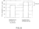
- FIG. 9 shows a graph indicating effective concentration of magnetic flux lines during magnetization with the magnetizing apparatus 100, i.e. indicating that the total magnetic flux, generated by the magnetizing apparatus 100 for an object to be magnetized, is effectively ensured.
- the graph shows data on the total magnetic flux of a magnetic field generated by the magnetizing apparatus 100 in comparison with data on the total magnetic flux of a magnetic field generated by a magnetizing apparatus (comparative magnetizing apparatus) in which a portion, corresponding to the housing 101 of the magnetizing apparatus 100, is formed of an aluminum alloy which is not a ferromagnetic material.
- the total magnetic flux refers to the total amount of magnetic flux present in the entire disposition space D.
- the total magnetic flux of the magnetic field generated by the magnetizing apparatus 100 is considerably higher, in particular by about 27%, than the total magnetic flux of the magnetic field generated by the comparative magnetizing apparatus.
- FIG. 10 is a diagram illustrating how the magnetization is performed.
- the rotor 20 of the radial-gap type superconducting synchronous machine 1 is first taken out of the stator 10. Thereafter, as shown in FIG. 10 , one magnetic pole 21 of the rotor 20 is inserted into the disposition space D of the magnetizing apparatus 100, and the magnetizing apparatus 100 comes to lie radially outside the magnetic pole 21 such that the bulk aggregate 24 of the magnetic pole 21 in the disposition space D is located opposite to and in close proximity to the core portion 101C.
- the magnetizing apparatus 100 is to be disposed such that the bulk aggregate 24 in the disposition space D is located nearer to the core portion 101C than the inner surface of the bottom wall portion 101E of the housing 101, and that the ferromagnet 28 of the radial-gap type superconducting synchronous machine 1 is located nearer to the core portion 101C than the outer surface of the bottom wall portion 101E.
- the magnetic pole 21 of the rotor 20 is inserted into the disposition space D by lowering the magnetizing apparatus 100.
- the projecting portion of the vacuum cover 3, covering the magnetic pole 21, is also disposed in the disposition space D.
- an electric current is supplied from the current supply section 104 (see FIG. 7 ) to the coil 102 to generate a magnetic field.
- magnetization is effected by directing the magnetic flux lines of the magnetizing apparatus 100 from the distal end part of the core portion 101C toward the bulk aggregate 24 of the radial-gap type superconducting synchronous machine 1.
- the electric current is continuously supplied to the coil 102 so that magnetization is effected by static magnetic field magnetization.
- FIG. 11 is a diagram showing a graph illustrating an example of temperature control of the bulk superconductors and timing of the application of a magnetic field in the magnetization according to this embodiment.
- the abscissa axis represents time
- the ordinate axis represents the temperature (K) of the bulk superconductors 30 and the magnetic flux density (T) of the magnetic field applied.
- the line L1 indicates the temperature of the bulk superconductors 30, and the line L2 indicates the magnetic flux density of the magnetic field generated by supplying an electric current to the coil 102.
- Tc represents the superconducting transition temperature.
- the application of static magnetic field (stationary magnetic field) to the bulk superconductors 30 is started under conditions that the temperature of the bulk superconductors 30 is controlled at a temperature higher than the superconducting transition temperature Tc.
- the temperature of the bulk superconductors 30 is lowered to a predetermined temperature (50 K in the illustrated example) lower than the superconducting transition temperature Tc while keeping the magnetic flux density at the target value.
- the bulk superconductors 30 are in a superconducting state from the superconducting transition temperature, which allows passage of magnetic flux lines through the bulk superconductors 30, when their temperature is lower than the superconducting transition temperature Tc.
- the magnetic field is applied for a predetermined period of time (about 60 minutes in the illustrated example) until the temperature of the bulk superconductors 30 reaches the predetermined temperature lower than the superconducting transition temperature Tc.
- a magnetic circuit is formed in which, as shown in FIG. 12 , magnetic flux flows in the following order: one end part (distal end part) of the core portion 101C ⁇ the bottom wall portion 101E ⁇ the peripheral wall portion 101S ⁇ the top wall portion 101T ⁇ the other end part (proximal end part) of the core portion 101C.
- the ferromagnet 28 because of the provision of the ferromagnet 28 in the radial-gap type superconducting synchronous machine 1, magnetic flux lines from the magnetizing apparatus 100 are guided so that they pass through the bulk aggregate 24 and reach the ferromagnet 28.
- the ferromagnet 28 is located nearer to the core portion 101C than the outer surface of the bottom wall portion 101E.
- a generally-rectangular magnetic circuit, running through the housing of the magnetizing apparatus 100 and the ferromagnet 28, is therefore formed. Since the bulk aggregate 24 is located in the straight line portion of the magnetic circuit, magnetic flux lines effectively pass through the bulk aggregate 24. Magnetization of the bulk aggregate 24 can therefore be performed efficiently.
- the supply of electric current to the coil 102 is stopped, i.e. the current applied to the coil 102 is made 0, whereby the magnetic field is eliminated as shown in FIG. 11 .
- the rotor 20 is rotated, and the magnetic pole 21 of the rotor 20, to be next magnetized, is disposed in the disposition space D of the magnetizing apparatus 100 and subjected to magnetization.
- the coil 102 is covered by the top wall portion 101T and the peripheral wall portion 101S of the housing 101 made of ferromagnetic material, and the peripheral wall portion 101S opens in the opposite direction from the top wall portion 101T.
- a magnetic circuit is therefore formed in which magnetic flux flows in the following order: one end part (distal end part) of the core portion 101C ⁇ the bottom wall portion 101E ⁇ the peripheral wall portion 101S ⁇ the top wall portion 101T ⁇ the other end part (proximal end part) of the core portion 101C.
- the peripheral wall portion 101S is provided with the bottom wall portion 101E made of a ferromagnetic material and extending from the distal end part of the peripheral wall portion 101S toward the core portion 101C.
- the bottom wall portion 101E extends to a position not overlapping the core portion 101C, and the disposition space D is formed in an area located opposite the distal end part of the core portion 101C and inside the inner periphery of the bottom wall portion 101E.
- the magnetic flux lines W flow from the one end part (distal end part) of the core portion 101C and reach the bottom wall portion 101E, the magnetic flux lines can be made more dense (concentrated) on a line extending from the one end part of the core portion 101C in the disposition space D. This further increases the efficiency of magnetization of an object to be magnetized.
- the ferromagnet 28 in the radial-gap type superconducting synchronous machine 1, a lot of magnetic flux lines W from the magnetizing apparatus 100 are guided so that they pass through the bulk aggregate 24 and reach the ferromagnet 28.
- the dense or concentrated magnetic flux lines can be passed through the bulk aggregate 24 composed of the bulk superconductors 30.
- the bulk aggregate 24 composed of the bulk superconductors 30 can be magnetized with high efficiency even though the coil 102 of the magnetizing apparatus 100 is disposed at a distance from the bulk aggregate 24, and the coil 102 is not a large-sized one surrounding the bulk aggregate 24.
- a sufficient captured magnetic flux can therefore be ensured in the bulk aggregate 24 even though magnetization is performed by the magnetizing apparatus 100 which is not large-sized.
- captured magnetic flux in the bulk aggregate 24 composed of the bulk superconductors 30 can be effectively increased while ensuring the practical utility. This makes it possible to increase the torque and the power output of the synchronous machine.
- the magnetizing apparatus 100 of this embodiment sufficient captured magnetic flux can thus be ensured in the bulk aggregate 24 even though the coil 102 lies at a distance from the bulk aggregate 24. Therefore, the degree of freedom of disposition that can ensure sufficient captured magnetic flux for the bulk aggregate 24 can be enhanced. The practical utility can be ensured also in this respect.
- the magnetizing apparatus 100 can be prevented from interfering with the neighbor magnetic pole(s). Sufficient captured magnetic flux can therefore be ensured in each of the plurality of magnetic poles.
- the magnetic pole center side of the bulk aggregate 24 when viewed in the direction of the rotational axis C1 of the rotor 20, the magnetic pole center side of the bulk aggregate 24 is disposed nearer to the stator 10 than the magnetic pole end side.
- the bulk aggregate 24 is disposed such that it follows the arc-shaped inner surface of the stator 10. This can reduce the gap between the bulk aggregate 24 and the stator 10, thereby making it possible to allow a magnetic field from the bulk aggregate 24 to efficiently act on the stator 10.
- the magnetized bulk aggregate 24 is attracted by the magnetic force to the housing 101 of ferromagnetic material, constituting the magnetizing apparatus 100, while, at the same time, the bulk aggregate 24 is attracted to the ferromagnet 28 located on the rotational axis C1 side of the bulk aggregate 24. This can prevent the bulk aggregate 24 from moving toward the magnetizing apparatus 100, thus enabling the bulk aggregate 24 to be held in the initial installation position.
- FIG. 13 is a diagram showing a table summarizing the performance of a radial-gap type superconducting synchronous machine of Example and the performances of conventional superconducting synchronous machines of Comp. Examples 1 to 3.
- the table of FIG. 13 shows data on the "model" of each of the synchronous machines of Example and Comp. Examples 1 to 3, "rotational speed", “torque” and “power output” as exemplary performance parameters, "superconducting material” used for a field system or an armature, “refrigerant or cooling method” for maintaining the superconducting material at a low temperature, and “captured magnetic flux density” in a magnetic pole.
- the radial-gap type superconducting synchronous machine 1 of Example was magnetized by the magnetizing apparatus 100 in the manner described above with reference to the above embodiment, whereby magnetic flux lines were captured by the bulk aggregate 24 of each magnetic pole 21.
- GdBCO was used for the bulk superconductors 30, and neon was used for the refrigerant.
- a very high captured magnetic flux density of, for example, 5.0 Tesla (T) is obtained, and a very high torque of 1508 Nm is obtained at a rotational speed of 190 rpm.
- the power output at that rotational speed was estimated to be 30 kW.
- the synchronous machine of Comp. Example 1 is a reluctance-type superconducting synchronous machine (radial-gap type) that uses a YBCO (YBa 2 Cu 3 O 7-z ) high-temperature superconducting bulk for a magnetic system pole, and liquid nitrogen as a refrigerant.
- the comparative synchronous machine was found to have a torque of 127 Nm at a rotational speed of 3000 rpm, and a power output of 40 kW at that rotational speed.
- the comparative data demonstrates that compared to the synchronous machine of Comp. Example 1, the synchronous machine of Example can obtain a significantly higher torque at a lower rotational speed. This indicates that the synchronous machine of Example can promptly obtain a high output as compared to the synchronous machine of Comp. Example 1.
- the synchronous machine of Comp. Example 2 is a radial-gap type superconducting synchronous machine that uses a YBCO high-temperature superconducting bulk for a magnetic system pole, and uses direct conduction cooling as a cooling method.
- the comparative synchronous machine was found to have a torque of 24 Nm at a rotational speed of 600 rpm, and a power output of 1.5 kW at that rotational speed.
- the comparative data demonstrates that compared to the synchronous machine of Comp. Example 2, the synchronous machine of Example can obtain a significantly higher torque at a lower rotational speed. This indicates that the synchronous machine of Example can promptly obtain a significantly higher output as compared to the synchronous machine of Comp. Example 1.
- the synchronous machine of Comp. Example 3 is an axial-gap type superconducting synchronous machine that uses a GdBCO superconducting material for a magnetic system, and liquid nitrogen as a refrigerant, and has a captured magnetic flux density of 0.8 to 0.9 T.
- the comparative synchronous machine was found to have a torque of 212 Nm at a rotational speed of 720 rpm, and a power output of 16 kW at that rotational speed.
- the comparative data demonstrates that the synchronous machine of Comp. Example 3 can obtain a high torque at a relatively low rotational speed, but is inferior to the synchronous machine of Example.
- the comparative data indicates that the synchronous machine of Example can promptly obtain a significantly higher output as compared to the synchronous machine of Comp. Example 3.
- the bulk superconductor was magnetized by pulse magnetization.
- the bulk aggregate 24 of the radial-gap type superconducting synchronous machine 1 is composed of the 15 bulk superconductors 30, the number of the bulk superconductors 30 is not limited to 15; for example, only one bulk superconductor may be provided in each magnetic pole 21. Further, the material of the bulk superconductors 30 is not limited to GdBCO.
- the radial-gap type superconducting synchronous machine 1 has the four magnetic poles 21, the number of the magnetic poles is not limited to four.
- stator 10 of the radial-gap type superconducting synchronous machine 1 has a cylindrical shape having a circular cross-section and which is relatively long in the axial direction
- stator 10 may have an annular shape which is relatively short in the axial direction.
- the stator 10 preferably has an annular shape.
- the bulk superconductors 30 of the above-described embodiment have a rectangular shape as viewed from radially outside, it is possible to use other shapes such as a circular shape.
- a superconducting wire rod may be used in the radial-gap type superconducting synchronous machine 1.
- the housing 101 of the magnetizing apparatus 100 may not necessarily have the bottom wall portion 101E, the provision of the bottom wall portion 101E can increase the efficiency of magnetization.
Landscapes
- Engineering & Computer Science (AREA)
- Power Engineering (AREA)
- Manufacturing & Machinery (AREA)
- Superconductive Dynamoelectric Machines (AREA)
- Permanent Field Magnets Of Synchronous Machinery (AREA)
Claims (8)
- Supraleitende Radialspalt-Synchronmaschine (1), die umfasst:einen Stator (10), der eine kreisförmige Querschnittsform aufweist;einen Rotor (20), der drehbar im Inneren des Stators (10) getragen wird; undeinen Supraleiter (30), der auf der Umfangsseite des Rotors angeordnet ist,wobei der Rotor (20) einen Rotorkörper (22), der an einer Drehwelle (2) gesichert ist, und einen konvexen Magnetpol (21) umfasst, der an dem Umfang des Rotorkörpers (22) bereitgestellt ist, wobei der Magnetpol (21) radial nach außen hervorsteht,
wobei der Magnetpol (21) an seinem radial distalen Endteil den Supraleiter (30) umfasst,
wobei, in der Richtung einer Drehachse (C1) des Rotors (20) betrachtet, der Magnetpol-Mittelabschnitt (21) des Supraleiters (30) näher an dem Stator (10) angeordnet ist als die Magnetpol-Endabschnitte (21) des Supraleiters (30), und
wobei ein Ferromagnet (28) an der Seite der Drehachse (C1) des Supraleiters (30) in dem Magnetpol (21) angeordnet ist. - Supraleitende Radialspalt-Synchronmaschine (1) nach Anspruch 1, wobei der Supraleiter (30) in mehreren Anzahlen an dem distalen Endteil des Magnetpols (21) angeordnet ist und die Vielzahl von Supraleitern (30) in einer abgestuften Anordnung angeordnet sind, die derart ist, dass, in der Richtung der Drehachse (C1) des Rotors (20) betrachtet, ein Supraleiter (30), der am nächsten an der Mitte des Magnetpols (21) liegt, sich näher an dem Stator (10) befindet als die anderen Supraleiter (30) .
- Supraleitende Radialspalt-Synchronmaschine (1) nach Anspruch 1, wobei der Supraleiter (30) von außen in der radialen Richtung des Rotors (20) betrachtet eine rechtwinklige Form aufweist.
- Supraleitende Radialspalt-Synchronmaschine (1) nach Anspruch 1, wobei der Supraleiter (30) in mehreren Anzahlen am distalen Endteil des Magnetpols (21) angeordnet ist und die Vielzahl von Supraleitern (30) derart an dem distalen Endteil des Magnetpols (21) angeordnet sind, dass sie in der Umfangsrichtung des Rotors (20) angeordnet sind und dass sie in der Richtung der Drehachse (C1) des Rotors (20) angeordnet sind.
- Magnetisierungsvorrichtung (100) zum Magnetisieren einer supraleitenden Radialspalt-Synchronmaschine (1), die umfasst:ein aus einem ferromagnetischen Material bestehendes Gehäuse (101), das einen oberen Wandabschnitt (101T), einen Umfangswandabschnitt (101S), der sich von einem Umfangsabschnitt des oberen Wandabschnitts (101T) vertikal nach unten erstreckt, und einen Kernabschnitt (101C) umfasst, der sich im Inneren des Umfangswandabschnitts (101S) befindet und sich von der inneren Oberfläche des oberen Wandabschnitts (101T) vertikal nach unten erstreckt;eine Spule (102), die in dem Gehäuse (101) untergebracht ist, wobei die Spule (102) um den Kernabschnitt (101C) gewickelt ist und von dem oberen Wandabschnitt (101T) und dem Umfangswandabschnitt (101S) bedeckt ist; undeine Stromversorgungssektion (104) zum Versorgen der Spule (102) mit einem elektrischen Strom, wobei der Umfangswandabschnitt (101S) sich in der von dem oberen Wandabschnitt (101T) entgegengesetzten Richtung öffnet, und die Höhe des Umfangswandabschnitts (101S) von dem oberen Wandabschnitt (101T) größer als die Höhe des Kernabschnitts (101C) von dem oberen Wandabschnitt (101T) ist,wobei ein Anordnungsraum (D) für ein zu magnetisierendes Objekt in einem Bereich gebildet ist, der sich dem distalen Endteil des Kernabschnitts (101C) entgegengesetzt befindet und sich im Inneren des Umfangswandabschnitts (101S) befindet,
wobei der Umfangswandabschnitt (101S) mit einem aus einem ferromagnetischen Material bestehenden unteren Wandabschnitt (101E) versehen ist, der sich von dem distalen Endteil des Umfangswandabschnitts (101S) hin zu dem Kernabschnitt (101C) erstreckt,
wobei der untere Wandabschnitt (101E), in der Richtung betrachtet, in der der Kernabschnitt (101C) sich vertikal nach unten erstreckt, sich zu einer Position erstreckt, die sich nicht mit dem Kernabschnitt (101C) überschneidet,
wobei der Anordnungsraum (D) in einem Bereich gebildet ist, der sich dem distalen Endabschnitt des Kernabschnitts (101C) entgegengesetzt befindet und sich im Inneren des inneren Umfangs des unteren Wandabschnitts (101E) befindet,
wobei der untere Wandabschnitt (101E) eine offene Struktur in der Richtung aufweist, in der sich der Kernabschnitt (101C) vertikal erstreckt, um in der Lage zu sein, das zu magnetisierende Objekt durch den Raum im Inneren des inneren Umfangs des unteren Wandabschnitts (101E) einzuführen und das zu magnetisierende Objekt in dem Anordnungsraum (D) zu positionieren, und
wobei die Magnetisierungsvorrichtung (100) derart ausgestaltet ist, dass der Anordnungsraum (D) sich näher an dem Kernabschnitt (101C) befindet als die innere Oberfläche des unteren Wandabschnitts (101E). - Magnetisierungsverfahren zum Magnetisieren einer supraleitenden Radialspalt-Synchronmaschine (1), die einen Stator (10), der eine kreisförmige Querschnittsform aufweist, einen Rotor (20), der drehbar im Inneren des Stators (10) getragen wird, und einen Supraleiter (30) umfasst, der an der Umfangsseite des Rotors (20) angeordnet ist, wobei das Verfahren die folgenden Schritte umfasst:Herstellen der supraleitenden Radialspalt-Synchronmaschine (1), wobei der Rotor (20) einen Rotorkörper (22), der an einer Drehwelle (2) gesichert ist, und einen konvexen Magnetpol (21) umfasst, der an dem Umfang des Rotorkörpers (22) bereitgestellt ist, wobei der Magnetpol (21) radial nach außen hervorsteht, wobei der Magnetpol (21) an seinem radial distalen Endteil den Supraleiter (30) umfasst, wobei, in der Richtung einer Drehachse (C1) des Rotors (20) betrachtet, der Magnetpol-Mittelabschnitt (21) des Supraleiters (30) näher an dem Stator (10) angeordnet ist als die Magnetpol-Endabschnitte (21) des Supraleiters (30) und wobei ein Ferromagnet (28) an der Seite der Drehachse des Supraleiters in dem Magnetpol (21) angeordnet ist;Herausnehmen des Rotors (20) aus dem Stator (10);Anordnen einer Magnetisierungsvorrichtung (100) außerhalb des Supraleiters (30) in der radialen Richtung des Rotors (20); undDurchführen von Magnetisierung durch Richten magnetischer Feldlinien von der Magnetisierungsvorrichtung (100) hin zu dem Supraleiter (30) .
- Magnetisierungsverfahren nach Anspruch 6, wobei die Magnetisierungsvorrichtung (100) umfasst: ein aus einem ferromagnetischen Material bestehendes Gehäuse (101), das einen oberen Wandabschnitt (101T), einen Umfangswandabschnitt (101S), der sich von einem Umfangsabschnitt des oberen Wandabschnitts (101T) vertikal nach unten erstreckt, und einen Kernabschnitt (101C) umfasst, der sich im Inneren des Umfangswandabschnitts (101S) erstreckt und sich von der inneren Oberfläche des oberen Wandabschnitts (101T) vertikal nach unten erstreckt; eine Spule (102), die in dem Gehäuse (101) untergebracht ist, wobei die Spule (102) um den Kernabschnitt (101C) gewickelt ist und von dem oberen Wandabschnitt (101T) und dem Umfangswandabschnitt (101S) bedeckt ist; und eine Stromversorgungssektion (104) zum Versorgen der Spule (102) mit einem elektrischen Strom, wobei der Umfangswandabschnitt (101S) sich in die von dem oberen Wandabschnitt (101T) entgegengesetzte Richtung öffnet, und die Höhe des Umfangswandabschnitts (101S) von dem oberen Wandabschnitt (101T) größer als die Höhe des Kernabschnitts (101C) von dem oberen Wandabschnitt (101T) ist, und wobei ein Anordnungsraum (D) für ein zu magnetisierendes Objekt in einem Bereich gebildet ist, der sich dem distalen Endteil des Kernabschnitts (101C) entgegengesetzt befindet und sich im Inneren des Umfangswandabschnitts (101S) befindet, und in dem Schritt des Anordnens der Magnetisierungsvorrichtung (100) die Magnetisierungsvorrichtung (100) derart angeordnet wird, dass der Supraleiter (30) der supraleitenden Radialspalt-Synchronmaschine (1) sich in dem Anordnungsraum (D) der Magnetisierungsvorrichtung (100) befindet.
- Magnetisierungsverfahren nach Anspruch 7, wobei in der Magnetisierungsvorrichtung (100) der Umfangswandabschnitt (101S) mit einem aus einem ferromagnetischen Material bestehenden unteren Wandabschnitt (101E) versehen ist, der sich von dem distalen Endteil des Umfangswandabschnitts (101S) hin zu dem Kernabschnitt (101C) erstreckt, wobei der untere Wandabschnitt (101E), in der Richtung betrachtet, in der der Kernabschnitt (101C) sich vertikal nach unten erstreckt, sich zu einer Position erstreckt, die sich nicht mit dem Kernabschnitt (101C) überschneidet, und wobei der Anordnungsraum (D) in einem Bereich gebildet ist, der sich dem distalen Endteil des Kernabschnitts (101C) entgegengesetzt befindet und sich im Inneren des inneren Umfangs des unteren Wandabschnitts (101E) befindet, und im Schritt des Anordnens der Magnetisierungsvorrichtung (100) die Magnetisierungsvorrichtung (100) derart angeordnet wird, dass der Supraleiter (30) in dem Anordnungsraum (D) der Magnetisierungsvorrichtung (100) sich näher an dem Kernabschnitt (101C) befindet als der untere Wandabschnitt (101E).
Applications Claiming Priority (2)
| Application Number | Priority Date | Filing Date | Title |
|---|---|---|---|
| JP2014069925 | 2014-03-28 | ||
| PCT/JP2015/059155 WO2015147068A1 (ja) | 2014-03-28 | 2015-03-25 | ラジアルギャップ型超電導同期機、着磁装置、及び着磁方法 |
Publications (3)
| Publication Number | Publication Date |
|---|---|
| EP3125415A1 EP3125415A1 (de) | 2017-02-01 |
| EP3125415A4 EP3125415A4 (de) | 2018-01-10 |
| EP3125415B1 true EP3125415B1 (de) | 2021-04-21 |
Family
ID=54195579
Family Applications (1)
| Application Number | Title | Priority Date | Filing Date |
|---|---|---|---|
| EP15769533.9A Active EP3125415B1 (de) | 2014-03-28 | 2015-03-25 | Supraleitender radialspalt-synchronmaschine, magnetisierungsvorrichtung und magnetisierungsverfahren |
Country Status (4)
| Country | Link |
|---|---|
| US (2) | US10594197B2 (de) |
| EP (1) | EP3125415B1 (de) |
| JP (1) | JP6566483B2 (de) |
| WO (1) | WO2015147068A1 (de) |
Families Citing this family (6)
| Publication number | Priority date | Publication date | Assignee | Title |
|---|---|---|---|---|
| DE102016205216A1 (de) * | 2016-03-30 | 2017-10-05 | Siemens Aktiengesellschaft | Elektrische Maschine mit supraleitfähigem Permanentmagneten und Verfahren zum Magnetisieren des Permanentmagneten |
| JP6982522B2 (ja) * | 2018-03-08 | 2021-12-17 | 三菱重工業株式会社 | 超電導回転機械用ステータ、及び超電導回転機械 |
| DE102018215917A1 (de) * | 2018-08-21 | 2020-02-27 | Siemens Aktiengesellschaft | Rotor mit Rotorwicklung für Betrieb im Dauerstrommodus |
| DE102018216890A1 (de) * | 2018-10-02 | 2020-04-02 | Rolls-Royce Deutschland Ltd & Co Kg | Rotor und Maschine mit supraleitendem Permanentmagneten |
| DE102018217983A1 (de) * | 2018-10-22 | 2020-04-23 | Rolls-Royce Deutschland Ltd & Co Kg | Rotor und Maschine mit supraleitendem Permanentmagneten in einem Rotorträger |
| CN114498970B (zh) * | 2022-03-02 | 2023-12-01 | 北京交通大学 | 一种超导同步电机充磁结构及方法 |
Family Cites Families (16)
| Publication number | Priority date | Publication date | Assignee | Title |
|---|---|---|---|---|
| JPS5142285B1 (de) * | 1969-10-09 | 1976-11-15 | ||
| JPH02111238A (ja) | 1988-10-17 | 1990-04-24 | Fanuc Ltd | 永久磁石形同期電動機 |
| US5177054A (en) * | 1991-04-08 | 1993-01-05 | Emerson Electric Co. | Flux trapped superconductor motor and method therefor |
| JPH05219717A (ja) | 1992-02-07 | 1993-08-27 | Mitsubishi Heavy Ind Ltd | 超電導モータ |
| US6111490A (en) * | 1996-06-19 | 2000-08-29 | Aisin Seiki Kabushiki Kaisha | Superconducting magnet apparatus and method for magnetizing superconductor |
| US7453174B1 (en) * | 1999-08-10 | 2008-11-18 | American Superconductor Corporation | Superconducting electric motor |
| US6707209B2 (en) | 2000-12-04 | 2004-03-16 | Emerson Electric Co. | Reduced cogging torque permanent magnet electric machine with rotor having offset sections |
| JP2003332128A (ja) * | 2002-05-15 | 2003-11-21 | Toshiba Corp | 磁石製造用金型装置,磁石の製造方法,異方性磁石及び永久磁石モータ |
| US7750524B2 (en) * | 2003-01-09 | 2010-07-06 | University Of Fukui | Superconductor magnetizing device and superconducting synchronization device |
| JP4152898B2 (ja) | 2003-01-09 | 2008-09-17 | 国立大学法人福井大学 | バルク超電導体の着磁装置、着磁方法及び超電導同期機 |
| DE10335040B4 (de) * | 2003-08-01 | 2009-09-03 | Siemens Ag | Elektrische Maschine mit ferromagnetischem Polkern ihres Rotors |
| JP4895714B2 (ja) * | 2006-07-31 | 2012-03-14 | アイシン精機株式会社 | 超電導体、超電導磁場発生素子、超電導磁場発生装置および核磁気共鳴装置 |
| JP5062263B2 (ja) * | 2010-01-08 | 2012-10-31 | 住友電気工業株式会社 | 超電導コイル機器、超電導機器、および超電導コイル機器の製造方法 |
| JP5162654B2 (ja) | 2010-12-28 | 2013-03-13 | トヨタ自動車株式会社 | 超電導モータ |
| DE102011079725A1 (de) | 2011-07-25 | 2013-01-31 | Siemens Aktiengesellschaft | Elektrische Maschine und Verfahren zu deren Betrieb |
| JP6057204B2 (ja) * | 2012-09-11 | 2017-01-11 | 川崎重工業株式会社 | 超電導界磁極 |
-
2015
- 2015-03-25 JP JP2016510432A patent/JP6566483B2/ja active Active
- 2015-03-25 WO PCT/JP2015/059155 patent/WO2015147068A1/ja not_active Ceased
- 2015-03-25 US US15/300,220 patent/US10594197B2/en active Active
- 2015-03-25 EP EP15769533.9A patent/EP3125415B1/de active Active
-
2020
- 2020-02-10 US US16/786,673 patent/US11502590B2/en active Active
Non-Patent Citations (1)
| Title |
|---|
| YUDONG JIANG ET AL: "Magnetization Process of an HTS Motor and the Torque Ripple Suppression", IEEE TRANSACTIONS ON APPLIED SUPERCONDUCTIVITY, IEEE SERVICE CENTER, LOS ALAMITOS, CA, US, vol. 19, no. 3, 1 June 2009 (2009-06-01), pages 1644 - 1647, XP011257293, ISSN: 1051-8223 * |
Also Published As
| Publication number | Publication date |
|---|---|
| US10594197B2 (en) | 2020-03-17 |
| US20170310201A1 (en) | 2017-10-26 |
| US11502590B2 (en) | 2022-11-15 |
| JP6566483B2 (ja) | 2019-08-28 |
| EP3125415A4 (de) | 2018-01-10 |
| US20200251971A1 (en) | 2020-08-06 |
| JPWO2015147068A1 (ja) | 2017-04-13 |
| EP3125415A1 (de) | 2017-02-01 |
| WO2015147068A1 (ja) | 2015-10-01 |
Similar Documents
| Publication | Publication Date | Title |
|---|---|---|
| US11502590B2 (en) | Radial-gap type superconducting synchronous machine, magnetizing apparatus, and magnetizing method | |
| Qu et al. | Review of superconducting generator topologies for direct-drive wind turbines | |
| US20080161189A1 (en) | Superconducting Electrical Machines | |
| US8084909B2 (en) | Dual armature motor/generator with flux linkage | |
| JP6461385B2 (ja) | 超電導モータ及び発電機 | |
| US7489060B2 (en) | Superconducting rotating machines with stationary field coils | |
| US8008826B2 (en) | Brushless motor/generator with trapped-flux superconductors | |
| US7492073B2 (en) | Superconducting rotating machines with stationary field coils | |
| JP2010213561A (ja) | 超伝導回転機の固定子冷却構造 | |
| CN106664000A (zh) | 电磁装置 | |
| Xu et al. | Performance comparison of 10-MW wind turbine generators with HTS, copper, and PM excitation | |
| Lee et al. | Exploring fully superconducting air-core machine topology for off-shore wind turbine applications | |
| JP5043955B2 (ja) | 超伝導同期電動機 | |
| JP5278907B2 (ja) | 超電導回転機および超電導回転機システム | |
| Watasaki et al. | Stability model of bulk HTS field pole of a synchronous rotating machine under load conditions | |
| WO2022160514A1 (zh) | 无换向装置超导直流电机 | |
| Wang et al. | Design and experiment of an HTS flux-switching machine with stationary seal | |
| US7291958B2 (en) | Rotating back iron for synchronous motors/generators | |
| RU169041U1 (ru) | Сверхпроводниковая синхронная электрическая машина | |
| CN101282050A (zh) | 一种蒸发冷却电机无槽定子 | |
| JP7616691B2 (ja) | 超電導回転機 | |
| JP7724526B2 (ja) | 超電導回転機、並びに、これを用いた船舶、自動車、航空機及びポンプ | |
| US20210375541A1 (en) | Electrical machine and method for fabrication of a coil of an electrical machine | |
| Miki et al. | Applied HTS Bulks and Wires to Rotating Machines for Marine Propulsion | |
| EP3609060A1 (de) | Generator mit supraleitenden spulenwicklungen |
Legal Events
| Date | Code | Title | Description |
|---|---|---|---|
| STAA | Information on the status of an ep patent application or granted ep patent |
Free format text: STATUS: THE INTERNATIONAL PUBLICATION HAS BEEN MADE |
|
| PUAI | Public reference made under article 153(3) epc to a published international application that has entered the european phase |
Free format text: ORIGINAL CODE: 0009012 |
|
| STAA | Information on the status of an ep patent application or granted ep patent |
Free format text: STATUS: REQUEST FOR EXAMINATION WAS MADE |
|
| 17P | Request for examination filed |
Effective date: 20161028 |
|
| AK | Designated contracting states |
Kind code of ref document: A1 Designated state(s): AL AT BE BG CH CY CZ DE DK EE ES FI FR GB GR HR HU IE IS IT LI LT LU LV MC MK MT NL NO PL PT RO RS SE SI SK SM TR |
|
| AX | Request for extension of the european patent |
Extension state: BA ME |
|
| DAV | Request for validation of the european patent (deleted) | ||
| DAX | Request for extension of the european patent (deleted) | ||
| A4 | Supplementary search report drawn up and despatched |
Effective date: 20171211 |
|
| RIC1 | Information provided on ipc code assigned before grant |
Ipc: H01F 6/00 20060101ALI20171205BHEP Ipc: H02K 55/04 20060101ALI20171205BHEP Ipc: H02K 1/02 20060101ALI20171205BHEP Ipc: H01F 13/00 20060101ALI20171205BHEP Ipc: H02K 21/14 20060101ALI20171205BHEP Ipc: H02K 1/27 20060101ALI20171205BHEP Ipc: H02K 15/03 20060101ALI20171205BHEP Ipc: H02K 55/02 20060101AFI20171205BHEP |
|
| STAA | Information on the status of an ep patent application or granted ep patent |
Free format text: STATUS: EXAMINATION IS IN PROGRESS |
|
| 17Q | First examination report despatched |
Effective date: 20200204 |
|
| GRAP | Despatch of communication of intention to grant a patent |
Free format text: ORIGINAL CODE: EPIDOSNIGR1 |
|
| STAA | Information on the status of an ep patent application or granted ep patent |
Free format text: STATUS: GRANT OF PATENT IS INTENDED |
|
| INTG | Intention to grant announced |
Effective date: 20201117 |
|
| GRAS | Grant fee paid |
Free format text: ORIGINAL CODE: EPIDOSNIGR3 |
|
| GRAA | (expected) grant |
Free format text: ORIGINAL CODE: 0009210 |
|
| STAA | Information on the status of an ep patent application or granted ep patent |
Free format text: STATUS: THE PATENT HAS BEEN GRANTED |
|
| AK | Designated contracting states |
Kind code of ref document: B1 Designated state(s): AL AT BE BG CH CY CZ DE DK EE ES FI FR GB GR HR HU IE IS IT LI LT LU LV MC MK MT NL NO PL PT RO RS SE SI SK SM TR |
|
| REG | Reference to a national code |
Ref country code: GB Ref legal event code: FG4D |
|
| REG | Reference to a national code |
Ref country code: CH Ref legal event code: EP |
|
| REG | Reference to a national code |
Ref country code: DE Ref legal event code: R096 Ref document number: 602015068392 Country of ref document: DE Ref country code: IE Ref legal event code: FG4D |
|
| REG | Reference to a national code |
Ref country code: AT Ref legal event code: REF Ref document number: 1385687 Country of ref document: AT Kind code of ref document: T Effective date: 20210515 |
|
| REG | Reference to a national code |
Ref country code: SE Ref legal event code: TRGR |
|
| REG | Reference to a national code |
Ref country code: LT Ref legal event code: MG9D |
|
| REG | Reference to a national code |
Ref country code: AT Ref legal event code: MK05 Ref document number: 1385687 Country of ref document: AT Kind code of ref document: T Effective date: 20210421 |
|
| REG | Reference to a national code |
Ref country code: NL Ref legal event code: MP Effective date: 20210421 |
|
| PG25 | Lapsed in a contracting state [announced via postgrant information from national office to epo] |
Ref country code: BG Free format text: LAPSE BECAUSE OF FAILURE TO SUBMIT A TRANSLATION OF THE DESCRIPTION OR TO PAY THE FEE WITHIN THE PRESCRIBED TIME-LIMIT Effective date: 20210721 Ref country code: AT Free format text: LAPSE BECAUSE OF FAILURE TO SUBMIT A TRANSLATION OF THE DESCRIPTION OR TO PAY THE FEE WITHIN THE PRESCRIBED TIME-LIMIT Effective date: 20210421 Ref country code: HR Free format text: LAPSE BECAUSE OF FAILURE TO SUBMIT A TRANSLATION OF THE DESCRIPTION OR TO PAY THE FEE WITHIN THE PRESCRIBED TIME-LIMIT Effective date: 20210421 Ref country code: FI Free format text: LAPSE BECAUSE OF FAILURE TO SUBMIT A TRANSLATION OF THE DESCRIPTION OR TO PAY THE FEE WITHIN THE PRESCRIBED TIME-LIMIT Effective date: 20210421 Ref country code: NL Free format text: LAPSE BECAUSE OF FAILURE TO SUBMIT A TRANSLATION OF THE DESCRIPTION OR TO PAY THE FEE WITHIN THE PRESCRIBED TIME-LIMIT Effective date: 20210421 Ref country code: LT Free format text: LAPSE BECAUSE OF FAILURE TO SUBMIT A TRANSLATION OF THE DESCRIPTION OR TO PAY THE FEE WITHIN THE PRESCRIBED TIME-LIMIT Effective date: 20210421 |
|
| PG25 | Lapsed in a contracting state [announced via postgrant information from national office to epo] |
Ref country code: ES Free format text: LAPSE BECAUSE OF FAILURE TO SUBMIT A TRANSLATION OF THE DESCRIPTION OR TO PAY THE FEE WITHIN THE PRESCRIBED TIME-LIMIT Effective date: 20210421 Ref country code: PT Free format text: LAPSE BECAUSE OF FAILURE TO SUBMIT A TRANSLATION OF THE DESCRIPTION OR TO PAY THE FEE WITHIN THE PRESCRIBED TIME-LIMIT Effective date: 20210823 Ref country code: PL Free format text: LAPSE BECAUSE OF FAILURE TO SUBMIT A TRANSLATION OF THE DESCRIPTION OR TO PAY THE FEE WITHIN THE PRESCRIBED TIME-LIMIT Effective date: 20210421 Ref country code: NO Free format text: LAPSE BECAUSE OF FAILURE TO SUBMIT A TRANSLATION OF THE DESCRIPTION OR TO PAY THE FEE WITHIN THE PRESCRIBED TIME-LIMIT Effective date: 20210721 Ref country code: RS Free format text: LAPSE BECAUSE OF FAILURE TO SUBMIT A TRANSLATION OF THE DESCRIPTION OR TO PAY THE FEE WITHIN THE PRESCRIBED TIME-LIMIT Effective date: 20210421 Ref country code: GR Free format text: LAPSE BECAUSE OF FAILURE TO SUBMIT A TRANSLATION OF THE DESCRIPTION OR TO PAY THE FEE WITHIN THE PRESCRIBED TIME-LIMIT Effective date: 20210722 Ref country code: LV Free format text: LAPSE BECAUSE OF FAILURE TO SUBMIT A TRANSLATION OF THE DESCRIPTION OR TO PAY THE FEE WITHIN THE PRESCRIBED TIME-LIMIT Effective date: 20210421 Ref country code: IS Free format text: LAPSE BECAUSE OF FAILURE TO SUBMIT A TRANSLATION OF THE DESCRIPTION OR TO PAY THE FEE WITHIN THE PRESCRIBED TIME-LIMIT Effective date: 20210821 |
|
| REG | Reference to a national code |
Ref country code: DE Ref legal event code: R097 Ref document number: 602015068392 Country of ref document: DE |
|
| PG25 | Lapsed in a contracting state [announced via postgrant information from national office to epo] |
Ref country code: CZ Free format text: LAPSE BECAUSE OF FAILURE TO SUBMIT A TRANSLATION OF THE DESCRIPTION OR TO PAY THE FEE WITHIN THE PRESCRIBED TIME-LIMIT Effective date: 20210421 Ref country code: DK Free format text: LAPSE BECAUSE OF FAILURE TO SUBMIT A TRANSLATION OF THE DESCRIPTION OR TO PAY THE FEE WITHIN THE PRESCRIBED TIME-LIMIT Effective date: 20210421 Ref country code: EE Free format text: LAPSE BECAUSE OF FAILURE TO SUBMIT A TRANSLATION OF THE DESCRIPTION OR TO PAY THE FEE WITHIN THE PRESCRIBED TIME-LIMIT Effective date: 20210421 Ref country code: SK Free format text: LAPSE BECAUSE OF FAILURE TO SUBMIT A TRANSLATION OF THE DESCRIPTION OR TO PAY THE FEE WITHIN THE PRESCRIBED TIME-LIMIT Effective date: 20210421 Ref country code: SM Free format text: LAPSE BECAUSE OF FAILURE TO SUBMIT A TRANSLATION OF THE DESCRIPTION OR TO PAY THE FEE WITHIN THE PRESCRIBED TIME-LIMIT Effective date: 20210421 Ref country code: RO Free format text: LAPSE BECAUSE OF FAILURE TO SUBMIT A TRANSLATION OF THE DESCRIPTION OR TO PAY THE FEE WITHIN THE PRESCRIBED TIME-LIMIT Effective date: 20210421 |
|
| PLBE | No opposition filed within time limit |
Free format text: ORIGINAL CODE: 0009261 |
|
| STAA | Information on the status of an ep patent application or granted ep patent |
Free format text: STATUS: NO OPPOSITION FILED WITHIN TIME LIMIT |
|
| 26N | No opposition filed |
Effective date: 20220124 |
|
| PG25 | Lapsed in a contracting state [announced via postgrant information from national office to epo] |
Ref country code: IS Free format text: LAPSE BECAUSE OF FAILURE TO SUBMIT A TRANSLATION OF THE DESCRIPTION OR TO PAY THE FEE WITHIN THE PRESCRIBED TIME-LIMIT Effective date: 20210821 Ref country code: AL Free format text: LAPSE BECAUSE OF FAILURE TO SUBMIT A TRANSLATION OF THE DESCRIPTION OR TO PAY THE FEE WITHIN THE PRESCRIBED TIME-LIMIT Effective date: 20210421 |
|
| PG25 | Lapsed in a contracting state [announced via postgrant information from national office to epo] |
Ref country code: IT Free format text: LAPSE BECAUSE OF FAILURE TO SUBMIT A TRANSLATION OF THE DESCRIPTION OR TO PAY THE FEE WITHIN THE PRESCRIBED TIME-LIMIT Effective date: 20210421 |
|
| REG | Reference to a national code |
Ref country code: DE Ref legal event code: R119 Ref document number: 602015068392 Country of ref document: DE |
|
| PG25 | Lapsed in a contracting state [announced via postgrant information from national office to epo] |
Ref country code: MC Free format text: LAPSE BECAUSE OF FAILURE TO SUBMIT A TRANSLATION OF THE DESCRIPTION OR TO PAY THE FEE WITHIN THE PRESCRIBED TIME-LIMIT Effective date: 20210421 |
|
| REG | Reference to a national code |
Ref country code: CH Ref legal event code: PL |
|
| GBPC | Gb: european patent ceased through non-payment of renewal fee |
Effective date: 20220325 |
|
| REG | Reference to a national code |
Ref country code: BE Ref legal event code: MM Effective date: 20220331 |
|
| PG25 | Lapsed in a contracting state [announced via postgrant information from national office to epo] |
Ref country code: LU Free format text: LAPSE BECAUSE OF NON-PAYMENT OF DUE FEES Effective date: 20220325 Ref country code: LI Free format text: LAPSE BECAUSE OF NON-PAYMENT OF DUE FEES Effective date: 20220331 Ref country code: IE Free format text: LAPSE BECAUSE OF NON-PAYMENT OF DUE FEES Effective date: 20220325 Ref country code: GB Free format text: LAPSE BECAUSE OF NON-PAYMENT OF DUE FEES Effective date: 20220325 Ref country code: FR Free format text: LAPSE BECAUSE OF NON-PAYMENT OF DUE FEES Effective date: 20220331 Ref country code: DE Free format text: LAPSE BECAUSE OF NON-PAYMENT OF DUE FEES Effective date: 20221001 Ref country code: CH Free format text: LAPSE BECAUSE OF NON-PAYMENT OF DUE FEES Effective date: 20220331 |
|
| PG25 | Lapsed in a contracting state [announced via postgrant information from national office to epo] |
Ref country code: BE Free format text: LAPSE BECAUSE OF NON-PAYMENT OF DUE FEES Effective date: 20220331 |
|
| PG25 | Lapsed in a contracting state [announced via postgrant information from national office to epo] |
Ref country code: HU Free format text: LAPSE BECAUSE OF FAILURE TO SUBMIT A TRANSLATION OF THE DESCRIPTION OR TO PAY THE FEE WITHIN THE PRESCRIBED TIME-LIMIT; INVALID AB INITIO Effective date: 20150325 |
|
| PG25 | Lapsed in a contracting state [announced via postgrant information from national office to epo] |
Ref country code: MK Free format text: LAPSE BECAUSE OF FAILURE TO SUBMIT A TRANSLATION OF THE DESCRIPTION OR TO PAY THE FEE WITHIN THE PRESCRIBED TIME-LIMIT Effective date: 20210421 Ref country code: CY Free format text: LAPSE BECAUSE OF FAILURE TO SUBMIT A TRANSLATION OF THE DESCRIPTION OR TO PAY THE FEE WITHIN THE PRESCRIBED TIME-LIMIT Effective date: 20210421 |
|
| PG25 | Lapsed in a contracting state [announced via postgrant information from national office to epo] |
Ref country code: TR Free format text: LAPSE BECAUSE OF FAILURE TO SUBMIT A TRANSLATION OF THE DESCRIPTION OR TO PAY THE FEE WITHIN THE PRESCRIBED TIME-LIMIT Effective date: 20210421 |
|
| PG25 | Lapsed in a contracting state [announced via postgrant information from national office to epo] |
Ref country code: MT Free format text: LAPSE BECAUSE OF FAILURE TO SUBMIT A TRANSLATION OF THE DESCRIPTION OR TO PAY THE FEE WITHIN THE PRESCRIBED TIME-LIMIT Effective date: 20210421 |
|
| PGFP | Annual fee paid to national office [announced via postgrant information from national office to epo] |
Ref country code: SE Payment date: 20260319 Year of fee payment: 12 |