EP3125447A1 - Dispositif de communication optique, système de communication optique, et procédé de transmission optique - Google Patents
Dispositif de communication optique, système de communication optique, et procédé de transmission optique Download PDFInfo
- Publication number
- EP3125447A1 EP3125447A1 EP15769740.0A EP15769740A EP3125447A1 EP 3125447 A1 EP3125447 A1 EP 3125447A1 EP 15769740 A EP15769740 A EP 15769740A EP 3125447 A1 EP3125447 A1 EP 3125447A1
- Authority
- EP
- European Patent Office
- Prior art keywords
- wavelength
- optical
- light
- light output
- unit
- Prior art date
- Legal status (The legal status is an assumption and is not a legal conclusion. Google has not performed a legal analysis and makes no representation as to the accuracy of the status listed.)
- Withdrawn
Links
Images




Classifications
-
- H—ELECTRICITY
- H04—ELECTRIC COMMUNICATION TECHNIQUE
- H04J—MULTIPLEX COMMUNICATION
- H04J14/00—Optical multiplex systems
- H04J14/02—Wavelength-division multiplex systems
- H04J14/0227—Operation, administration, maintenance or provisioning [OAMP] of WDM networks, e.g. media access, routing or wavelength allocation
-
- H—ELECTRICITY
- H01—ELECTRIC ELEMENTS
- H01S—DEVICES USING THE PROCESS OF LIGHT AMPLIFICATION BY STIMULATED EMISSION OF RADIATION [LASER] TO AMPLIFY OR GENERATE LIGHT; DEVICES USING STIMULATED EMISSION OF ELECTROMAGNETIC RADIATION IN WAVE RANGES OTHER THAN OPTICAL
- H01S5/00—Semiconductor lasers
- H01S5/06—Arrangements for controlling the laser output parameters, e.g. by operating on the active medium
- H01S5/068—Stabilisation of laser output parameters
- H01S5/0683—Stabilisation of laser output parameters by monitoring the optical output parameters
- H01S5/0687—Stabilising the frequency of the laser
-
- H—ELECTRICITY
- H04—ELECTRIC COMMUNICATION TECHNIQUE
- H04B—TRANSMISSION
- H04B10/00—Transmission systems employing electromagnetic waves other than radio-waves, e.g. infrared, visible or ultraviolet light, or employing corpuscular radiation, e.g. quantum communication
- H04B10/50—Transmitters
- H04B10/501—Structural aspects
- H04B10/506—Multiwavelength transmitters
-
- H—ELECTRICITY
- H04—ELECTRIC COMMUNICATION TECHNIQUE
- H04B—TRANSMISSION
- H04B10/00—Transmission systems employing electromagnetic waves other than radio-waves, e.g. infrared, visible or ultraviolet light, or employing corpuscular radiation, e.g. quantum communication
- H04B10/50—Transmitters
- H04B10/572—Wavelength control
-
- H—ELECTRICITY
- H04—ELECTRIC COMMUNICATION TECHNIQUE
- H04B—TRANSMISSION
- H04B10/00—Transmission systems employing electromagnetic waves other than radio-waves, e.g. infrared, visible or ultraviolet light, or employing corpuscular radiation, e.g. quantum communication
- H04B10/60—Receivers
- H04B10/61—Coherent receivers
Definitions
- the present invention relates to an optical communication device, an optical communication system and an optical transmission method.
- PTL 1 discloses a technique of making the wavelength of an optical signal to be output from each of a plurality of optical transmitters coincide with the wavelength of a reference wavelength optical signal, by using a transmission wavelength variable filter.
- the reference wavelength optical signal is one of a plurality of optical signals whose wavelength intervals are constant, which are obtained by frequency-modulating a predetermined light source with an output from a microwave oscillator.
- the technique described in PTL 1 makes wavelength intervals of a plurality of optical signals to be output from a plurality of optical transmitters coincide with a wavelength interval generated by the microwave oscillator.
- each of a plurality of optical transmitters comprises the transmission wavelength variable filter, and each of the optical transmitters controls the transmission wavelength variable filter so that the intensity of a reference wavelength optical signal becomes a maximum.
- the optical transmitter then controls the wavelength of an optical signal to be output so that the wavelength of the optical signal to be output becomes a maximum at the transmission wavelength variable filter.
- the technique described in PTL 1 indirectly makes the wavelength of an optical signal to be output from each of a plurality of optical transmitters coincide with a reference wavelength optical signal by using a transmission wavelength variable filter.
- PTL 2 describes a frequency control method of an optical transmitter or an optical receiver used in a wavelength multiplexing optical communication network.
- a technique described in PTL 1 indirectly makes the wavelength contained in a reference wavelength optical signal coincide with the wavelength of an optical signal to be output from each of a plurality of optical transmitters by using a transmission wavelength variable filter.
- the wavelength of an optical signal to be adjusted depends on the accuracy of a transmission wavelength variable filter.
- the characteristics of a transmission wavelength variable filter change with temperature or time. This involves a shift in a wavelength of an optical signal to be adjusted and an overlap of optical spectra between adjacent channels deteriorates the transmission quality of a wavelength multiplexing optical signal, which is problematic.
- PTL 2 does not disclose a technique for solving such a problem.
- An object of the present invention is to solve the above-described problems and to provide an optical communication device or the like which can output a wavelength-multiplexed optical signal whose wavelength interval has higher accuracy.
- the optical communication device of the present invention includes: a plurality of light output unit that outputs optical signals having different wavelengths, a multiplexing unit that outputs a wavelength-multiplexed signal obtained by multiplexing a plurality of optical signals output from the plurality of light output units, a reference light output unit that outputs a reference light that is a reference, a wavelength generation unit that outputs, based on the reference light, a plurality of lights having a wavelength interval depending on a predetermined frequency, and a wavelength control unit that controls, depending on an interference component between the wavelength-multiplexed signal and a light having at least one wavelength among the plurality of lights, a wavelength of an optical signal output from the light output unit.
- the optical communication system of the present invention includes: an optical communication device includeing a plurality of light output unit that outputs optical signals having different wavelengths, a multiplexing unit that outputs a wavelength-multiplexed signal obtained by multiplexing a plurality of optical signals output from the plurality of light output unit, a reference light output unit that outputs a reference light that is a reference, a wavelength generation unit that outputs, based on the reference light, a plurality of lights having a wavelength interval depending on a predetermined frequency, and a wavelength control unit that controls, depending on an interference component between the wavelength-multiplexed signal and a light having at least one wavelength among the plurality of lights, a wavelength of an optical signal output from the light output unit; and a control device that instructs the optical communication device to control a wavelength of an optical signal output from at least one of the plurality of light output unit at a predetermined timing.
- the optical communication method of the present invention includes: outputting a plurality of optical signals having different wavelengths from light output unit; outputting the wavelength-multiplexed signal obtained by multiplexing a plurality of optical signals; outputting a reference light that is a reference; outputting, based on the reference light, a plurality of lights having a wavelength interval depending on a predetermined frequency; and controlling, depending on an interference component between the wavelength-multiplexed signal and a light having at least one wavelength among the plurality of lights, a wavelength of an optical signal output from the light output unit.
- the program recording medium for a program stores thereon a program for allowing a computer to execute: a processing of outputting optical signals having different wavelengths; a processing of outputting a wavelength-multiplexed signal obtained by multiplexing a plurality of optical signals output from the plurality of light output units; a processing of outputting a reference light that is a reference; a processing of outputting, based on the reference light, a plurality of lights having a wavelength interval depending on a predetermined frequency, and a processing of controlling, depending on an interference component between the wavelength-multiplexed signal and a light having at least one wavelength among the plurality of lights, a wavelength of an optical signal output from the light output unit.
- the optical communication device or the like of the present invention can advantageously output a wavelength-multiplexed optical signal whose wavelength interval has a higher accuracy.
- FIG. 1 is a diagram illustrating a configuration example of an optical communication device 1 in a first exemplary embodiment of the present invention.
- the optical communication device 1 comprises a plurality of light output units 10-1 to 10-N (unless there is a particular need for distinction, referred to as "light output unit 10"), a multiplexing unit 13, a reference light output unit 14, a wavelength generation unit 15, and a wavelength control unit 16.
- the plurality of light output units 10 output optical signals having different wavelengths.
- the multiplexing unit 13 outputs a wavelength-multiplexed signal obtained by multiplexing a plurality of optical signals output from the plurality of light output units 10 to the outside of the optical communication device 1.
- the multiplexing unit 13, for example, can branch part of a wavelength-multiplexed signal by an optical coupler or the like, and output the part of a wavelength-multiplexed signal to the wavelength control unit 16.
- the reference light output unit 14 outputs a reference light which is a reference for the wavelength of an optical signal to be output from each light output unit 10.
- the light output unit 10 and the reference light output unit 14 are, for example, a laser or the like which can output a coherent light.
- the type of the structure or the like of the laser is not restricted, and may be, for example, a variable wavelength laser or the like in which an output wavelength can be changed.
- the wavelength generation unit 15 outputs a plurality of lights having a wavelength interval corresponding to the frequency, for example, based on an electric signal having a frequency depending on a wavelength interval of each optical signal of a wavelength-multiplexed optical signal transmitted by a light transmission path.
- the wavelength generation unit 15 may output a plurality of lights, for example, by an optical comb generator which includes a combination of a phase modulator and a resonator.
- the wavelength control unit 16 compares a wavelength of a light from the wavelength generation unit 15 and a wavelength of a wavelength-multiplexed optical signal from the multiplexing unit 13.
- the wavelength control unit 16 compares a light from the wavelength generation unit 15 and a wavelength-multiplexed optical signal from the multiplexing unit 13 by directly interfering two input lights like, for example, an optical interferometer.
- the lights to be interfered may be, for example, part of an optical signal in a wavelength-multiplexed optical signal or part of a plurality of lights from the wavelength generation unit 15.
- a light of part of wavelengths can be taken out from a light of a plurality of wavelengths by an optical filter or the like.
- the wavelength control unit 16 controls a wavelength of an optical signal to be output from the light output unit 10 corresponding to the compared wavelength based on the compared result. For example, the wavelength control unit 16 controls a wavelength of an optical signal output from the light output unit 10 to eliminate a wavelength shift between a light from the wavelength generation unit 15 and a wavelength-multiplexed optical signal from the multiplexing unit 13. For example, the wavelength control unit 16 controls a wavelength of an optical signal output from the light output unit 10 to maximize the interference between two lights when a spectrointerferometer is used.
- the wavelength of an optical signal output from the light output unit 10 may be changed, for example, by the temperature or driving current of a laser or may be changed by controlling an oscillation wavelength in the case of a variable wavelength laser.
- FIG. 2 is a flow chart illustrating an operational example of an optical communication device 1 in the first exemplary embodiment of the present invention.
- a plurality of light output units 10 output optical signals having different wavelengths (S101).
- the multiplexing unit 13 outputs a wavelength-multiplexed signal obtained by multiplexing a plurality of optical signals output from a plurality of light output units 10 to the outside of the optical communication device 1, the multiplexing unit 13 branches part of the wavelength-multiplexed signal, and outputs part of the wavelength-multiplexed signal to the wavelength control unit 16 (S102).
- the reference light output unit 14 outputs a reference light which is a reference for a wavelength of an optical signal output from each light output unit 10 (S103).
- the wavelength generation unit 15 outputs a plurality of lights having a wavelength interval corresponding to the frequency, for example, based on an electric signal having a frequency depending on a wavelength interval of each optical signal of a wavelength-multiplexed optical signal transmitted by a light transmission path (S104).
- the wavelength control unit 16 compares a wavelength of a light from the wavelength generation unit 15 and a wavelength of a wavelength-multiplexed optical signal from the multiplexing unit 13, and controls a wavelength of an optical signal output from the light output unit 10 based on the compared result (S105).
- the wavelength control unit 16 of the optical communication device 1 of the first exemplary embodiment of the present invention directly compares a wavelength of a light from the wavelength generation unit 15 and a wavelength of a wavelength-multiplexed optical signal from the multiplexing unit 13, and controls a wavelength of an optical signal output from the light output unit 10 corresponding to the compared wavelength. Accordingly, the optical communication device 1 in the first exemplary embodiment of the present invention can output a wavelength-multiplexed optical signal whose wavelength interval has higher accuracy.
- a second exemplary embodiment of the present invention will be described with reference to the Drawings. Description of a configuration in the second exemplary embodiment of the present invention similar to that of the first exemplary embodiment of the present invention will be omitted.
- FIG. 3 is a diagram illustrating a configuration example of the optical communication device 1 in the second exemplary embodiment of the present invention.
- the optical communication device 1 in the second exemplary embodiment of the present invention comprises light output units 10-1 to 10-5, a multiplexing unit 13, a reference light output unit 14, a wavelength generation unit 15, a wavelength control unit 16, a wavelength selection unit 18, and a wavelength switching unit 19.
- the number of the light output units 10 is not restricted to five, and any number of the light output units 10 may be used.
- the wavelength generation unit 15 includes an optical comb generator 11 and a microwave oscillator 12.
- the wavelength control unit 16 comprises a comparison unit 17.
- a plurality of light output units 10 output optical signals having different wavelengths.
- the wavelength of an optical signal output from each of the plurality of light output units 10 is set to have a predetermined interval.
- the wavelength of an optical signal output from each of the plurality of light output units 10, however, may shift from a set wavelength due to device-specific optical frequency setting accuracy.
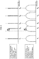
- FIG. 4 is a diagram illustrating an example of a state of frequencies corresponding to wavelengths of optical signals output from a plurality of light output units 10 and a state of optical spectrum of a plurality of optical signals included in a wavelength-multiplexed signal output from the multiplexing unit 13.
- FIG. 4 illustrates an example in which the frequency of an optical signal output from the light output unit 10-2 shifts by "+ ⁇ f". The frequency of an optical signal output from the light output unit 10 shifts from a desired frequency by "+ ⁇ f" due to, for example, a change with time.
- the fo is the frequency of a reference light output from the reference light output unit 14.
- the f m is a frequency interval of adjacent optical signals (i.e., between adjacent channels) output from the light output unit 10.
- optical spectra overlap between adjacent channels (an optical signal output from the light output unit 10-2 and an optical signal output from the light output unit 10-3) in a wavelength-multiplexed signal.
- the optical communication device 1 of the second exemplary embodiment of the present invention controls the wavelength of an optical signal output from at least one of a plurality of light output units 10 to make the wavelength of an optical signal output from the plurality of light output units 10 coincide with the wavelength of at least one of lights to be generated by the optical comb generator 11.
- the plurality of light output units 10 are controlled in such a way that optical spectra are not shifted between adjacent channels to a degree to which the optical spectra overlap.
- the temperatures or the like of the plurality of light output units 10 are controlled. For this reason, it is sufficient to consider a shift of a wavelength (a frequency corresponding to the wavelength) by which optical spectra between the adjacent channels overlap.
- the multiplexing unit 13 outputs a wavelength-multiplexed signal obtained by multiplexing optical signals output from a plurality of light output units 10 to the outside of the optical communication device 1.
- the multiplexing unit 13, for example, can branch part of a wavelength-multiplexed signal by an optical coupler or the like, and output the part of a wavelength-multiplexed signal to the comparison unit 17.
- the reference light output unit 14 outputs a reference light having a wavelength corresponding to a frequency fo which is a reference for the wavelength of an optical signal to be output from each light output unit 10.
- the reference light output from the reference light output unit 14 is input to the optical comb generator 11.
- a microwave oscillator 12 in the wavelength generation unit 15 outputs a clock signal (an electric signal) having a frequency F m .
- the frequency F m is, for example, 50 GHz or 40 GHz.
- the frequency F m of a clock signal corresponds to a wavelength interval of a plurality of optical signals output from the plurality of light output units 10.
- a clock signal output from the microwave oscillator 12 is input to the optical comb generator 11.
- an oscillator for modulation described in Japanese Patent No. 3444958 can be used.
- the optical comb generator 11 is driven by a clock signal input from the microwave oscillator 12, and generates a plurality of sideband lights (optical comb) having wavelengths corresponding to frequencies around the frequency fo at a frequency interval of F m when a reference light having a wavelength corresponding to the frequency fo is input.
- an optical comb generator described in Japanese Patent No. 3444958 can be used.
- the optical comb generator described in Japanese Patent No. 3444958 outputs an optical comb composed of several hundreds of optical spectral lines arranged around an optical frequency of a laser beam emitted from a wavelength stabilized light source at an optical frequency interval of fm.
- FIG. 5 is a diagram illustrating a state of a frequency of a reference light output from the reference light output unit 14, and a state of frequencies of an optical comb generated by the optical comb generator 11.
- a plurality of lights output from the optical comb generator 11 are an optical comb having a frequency interval of F m around a frequency fo of a reference light.
- the frequency interval of the optical comb generated by the optical comb generator 11 is highly accurately controlled, and highly accurately corresponds to a frequency F m of a clock signal input from the microwave oscillator 12.
- the wavelength selection unit 18 inputs, among a plurality of lights included in an optical comb generated by the optical comb generator 11, a light whose wavelength has been specified by the wavelength switching unit 19 to the comparison unit 17.
- a wavelength selection switch described in Japanese Patent No. 4748514 can be used for the wavelength selection unit 18.
- the wavelength selection switch can output a light having a desired wavelength among a plurality of input lights.
- the wavelength selection switch comprises an optical waveguide circuit formed on a substrate and control means for adding thermal variations to the optical waveguide circuit and performing switching control of an optical signal path, and can precisely control the wavelength of a light to be output.
- an optical signal detection device described in Japanese Patent No. 2758556 can be used.
- the optical signal detection device described in Japanese Patent No. 2758556 measures an interference intensity (interference component) which is a difference between input two optical signals.
- the comparison unit 17 detects a difference of wavelengths corresponding to a difference (" ⁇ f") between both of the optical signals.
- the wavelength control unit 16 controls the wavelength of an optical signal output from the light output unit 10 in such a way that the difference (shift) detected by the comparison unit 17 is compensated.
- a wavelength variable laser device described in Japanese Patent No. 3197869 can be used for the light output unit 10.
- a diffraction grating is used for a wavelength selecting element, and a wavelength to be output (to be selected) can be changed by adjusting the angle of the diffraction grating.
- the wavelength switching unit 19 specifies a wavelength to be selected by the wavelength selection unit 18, and requests the wavelength selection unit 18 to output a light having the specified wavelength.
- the wavelength switching unit 19 specifies a light output unit 10 which outputs an optical signal having the specified wavelength, and notifies the specified light output unit 10 (for example, a light output unit 10-2) to the wavelength control unit 16.
- FIG. 6 is a diagram illustrating a state of a frequency corresponding to the wavelength of a light selected by the wavelength selection unit 18 (specified by the wavelength switching unit 19) among a plurality of lights generated by the optical comb generator 11.
- FIG. 6 is a diagram illustrating states of a frequency corresponding to a wavelength of an optical signal output from the light output unit 10-2 before and after controlling a shift of a wavelength by the wavelength control unit 16.
- FIG. 6 is an example in which an optical signal output from the light output unit 10-2 shifts by a wavelength corresponding to a frequency ⁇ f, and the wavelength control unit 16 compensates a wavelength component corresponding to the frequency ⁇ f.
- the wavelength control unit 16 compensates a shift " ⁇ f" (a shift of wavelength correspond thereto) of a frequency of an optical signal output from the light output unit 10-2.
- the wavelength control unit 16 compensates a shift between both of the wavelengths by controlling to make a frequency of an optical signal output from the light output unit 10-2 coincide with a frequency "f 0 -F m " of a light selected by the wavelength selection unit 18.
- the wavelength switching unit 19 may control a wavelength of an optical signal to be output for all the light output units 10 while switching light output units 10-1 to 10-5 to be controlled and lights to be selected by the wavelength selection unit 18 in turn.
- the optical communication device 1 can make a wavelength interval of an optical signal output from each of the light output units 10-1 to 10-5 correspond to a frequency interval "F m " of a plurality of sideband lights (optical comb) generated by the optical comb generator 11.
- FIG. 7 is a flow chart illustrating an operational example of the optical communication device 1 in the second exemplary embodiment of the present invention.
- FIG. 7 is an example in which a wavelength of an optical signal output from the light output unit 10-2 shifts by a wavelength corresponding to a frequency "+ ⁇ f", and the wavelength of an optical signal output from the light output unit 10-2 is compensated.
- a plurality of light output units 10 output optical signals having different wavelengths (S201).
- a wavelength-multiplexed signal obtained by multiplexing a plurality of optical signals output from a plurality of light output units 10 is output to the outside of the optical communication device 1, part of the wavelength-multiplexed signal is branched, and the part of the wavelength-multiplexed signal is output to the comparison unit 17 (S202).
- the reference light output unit 14 outputs a reference light having a frequency fo which is a reference of a wavelength of an optical signal output from each light output unit 10 (S203).
- the wavelength generation unit 15 generates, based on a reference light having a wavelength corresponding to a frequency fo output from the reference light output unit 14, a plurality of lights having wavelengths around the frequency fo at a frequency interval of F m (S204).
- the wavelength selection unit 18 inputs, among the plurality of generated optical signals, a light whose wavelength has been specified by the wavelength switching unit 19 into the comparison unit 17 in the wavelength control unit 16 (S205).
- the comparison unit 17 compares a wavelength of a light from the wavelength generation unit 15 and a wavelength of a wavelength-multiplexed optical signal from the multiplexing unit 13, and as a result of the comparison, detects a difference between wavelengths corresponding to a difference (" ⁇ f") of both of the frequencies (S206).
- the wavelength control unit 16 controls a wavelength of an optical signal output from the light output unit 10-2 in such a way that a difference (shift) between wavelengths detected by the comparison unit 17 is compensated (S207).
- the wavelength control unit 16 of the optical communication device 1 of the second exemplary embodiment of the present invention directly compares a wavelength of a light from the wavelength generation unit 15 and a wavelength of a wavelength-multiplexed optical signal from the multiplexing unit 13, and controls a wavelength of an optical signal output from the light output unit 10 corresponding to the compared wavelength. Accordingly, the optical communication device 1 in the first exemplary embodiment of the present invention can output a wavelength-multiplexed optical signal whose wavelength interval has higher accuracy.
- the optical communication device 1 comprises a coherent detection unit. By using interference characteristics between a wavelength-multiplexed signal and a reference light, a frequency of an optical signal output from an LD 101 in the light output unit 10 is controlled.
- FIG. 8 is a diagram illustrating a configuration example of the optical communication device 1 in the third exemplary embodiment of the present invention.
- the optical communication device 1 in the third exemplary embodiment of the present invention comprises a coherent detection unit 20 and a wavelength shift detection unit 21 in place of the comparison unit 17.
- the optical communication device 1 comprises a branching device 22.
- the optical communication device 1 comprises LDs (Laser Diodes) 101-1 to 101-5 (unless there is a particular need for distinction, referred to as "LD 101”) and optical modulators 102-1 to 102-5 (unless there is a particular need for distinction, referred to as "optical modulator 102").
- LDs Laser Diodes
- the LD 101 outputs an optical signal having a predetermined frequency.
- a wavelength of an optical signal output from each of the plurality of LDs 101 is set to have a predetermined interval.
- the wavelength of an optical signal output from the LD 101 may have a predetermined shift with respect to the set wavelength due to device-specific optical frequency setting accuracy of the LD 101.
- the optical modulator 102 performs data modulation on an optical signal output from the LD 101, and outputs the signal to the multiplexing unit 13.
- the multiplexing unit 13 outputs a wavelength-multiplexed signal obtained by multiplexing a plurality of optical signals output from a plurality of light output units 10 to the branch unit 22.
- the branching device 22 branches a wavelength-multiplexed signal output from the multiplexing unit 13, and outputs one branched signal to a transmission path, and the other to the coherent detection unit 20.
- the wavelength selection unit 18 inputs, among a plurality of lights (sideband light) included in an optical comb generated by the optical comb generator 11, a light whose wavelength has been specified by the wavelength switching unit 19 into the coherent detection unit 20.
- the coherent detection unit 20 coherently detects a wavelength-multiplexed signal input from the branching device 22 and a light having a predetermined wavelength input from the wavelength selection unit 18.
- the coherent detection unit 20 outputs an interference signal between a wavelength-multiplexed signal input from the branching device 22 and the light input from the wavelength selection unit 18 to the wavelength shift detection unit 21.
- the coherent detection unit 20 comprises a 90-degree hybrid mixer (not illustrated) which is called a coherent mixer in which a wavelength-multiplexed signal input from the branching device 22 interferes with a light input from the wavelength selection unit 18.
- the coherent mixer outputs a signal (an interference signal) obtained when a wavelength-multiplexed signal input from the branching device 22 interferes with a light input from the wavelength selection unit 18.
- the wavelength shift detection unit 21 detects, based on an input interference signal, a difference (shift) of wavelengths between at least one optical signal included in a wavelength-multiplexed signal input from the wavelength selection unit 18 among wavelength-multiplexed signals and a light input from the wavelength selection unit 18.
- a frequency offset estimator in a frequency offset compensation device described in Japanese Patent No. 5146285 can be used.
- a frequency offset is a difference of frequencies between an input light and a local light.
- a baseband electric signal from a front-end circuit is input to the frequency offset estimator, then the frequency offset estimator estimates a frequency offset included in the baseband electric signal, and outputs the estimated frequency offset to a device in a latter step as an electric signal.
- the wavelength shift detection unit 21 outputs a difference (shift) of wavelengths corresponding to the estimated frequency offset as an electric signal.
- the wavelength control unit 16 adjusts a wavelength of an optical signal output from the light output unit 10 specified by the wavelength switching unit 19 among a plurality of light output units 10 in such a way that a difference (shift) of wavelengths detected by the wavelength shift detection unit 21 is compensated.
- a wavelength variable laser device described in Japanese Patent No. 3197869 can be used for the plurality of light output units 10.
- FIG. 9 is flow chart illustrating an operational example of the optical communication device 1 in the third exemplary embodiment of the present invention.
- FIG. 9 is an example in which a wavelength of an optical signal output from the light output unit 10-2 shifts by a wavelength corresponding to a frequency "+ ⁇ f", and the wavelength of an optical signal output from the light output unit 10-2 is compensated.
- the LDs 101 in the plurality of light output units 10 output optical signals having different wavelengths (S301).
- Each of the optical modulator 102 performs data modulation on an optical signal output from the LD 101, and outputs the signal to the multiplexing unit 13 (S302).
- the multiplexing unit 13 multiplexes optical signals output from the plurality of light output units 10, and outputs a wavelength-multiplexed signal (S303).
- the branching device 22 branches a wavelength-multiplexed signal output from the multiplexing unit 13, and outputs one branched signal to a transmission path, and the other to the coherent detection unit 20 (S304).
- the reference light output unit 14 outputs a reference light having a frequency fo which is a reference for a wavelength of an optical signal output from each light output unit 10 (S305).
- the wavelength generation unit 15 generates, based on a reference light having a wavelength corresponding to a frequency fo output from the reference light output unit 14, a plurality of lights having wavelengths around the frequency fo at a frequency interval of F m (S306).
- the wavelength selection unit 18 inputs, among the plurality of generated optical signals, a light whose wavelength has been specified by the wavelength switching unit 19 into the coherent detection unit 20 (S307).
- the coherent detection unit 20 outputs a signal (an interference signal) obtained when a wavelength of a light from the wavelength selection unit 18 interferes with a wavelength of a wavelength-multiplexed optical signal from the multiplexing unit 13 to the wavelength shift detection unit 21 (S308).
- the wavelength shift detection unit 21 detects, based on the interference signal, a difference (shift) of wavelengths between at least one optical signal included in a wavelength-multiplexed signal and a light input from the wavelength selection unit 18 (S309).
- the wavelength control unit 16 controls a wavelength of an optical signal output from an LD 101-2 in the light output unit 10-2 in such a way that the difference (shift) of wavelengths detected by the wavelength shift detection unit 21 is compensated (S310).
- the optical communication device 1 of the third exemplary embodiment of the present invention comprises the coherent detection unit 20, and controls the LD 102 in the light output unit 10 using interference characteristics by making a wavelength-multiplexed signal directly interfere with a reference light. Accordingly, the optical communication device 1 in the third exemplary embodiment of the present invention can output a wavelength-multiplexed optical signal whose wavelength interval has higher accuracy.
- a fourth exemplary embodiment of the present invention comprises a control device which instructs timing for controlling wavelength to the optical communication device 1.
- FIG. 10 is a diagram illustrating a configuration example of a communication system in a fourth exemplary embodiment of the present invention.
- the communication system in the fourth exemplary embodiment of the present invention comprises optical communication devices 1-1 to 1-4 (unless there is a particular need for distinction, referred to as "optical communication device 1 "), a transmission path 2, and a control device 3.
- optical communication device 1 there are four optical communication devices 1, the number of the optical communication devices 1 is not limited to four, and any number of the optical communication devices 1 may be used.
- the transmission path 2 is constituted of optical fibers, and may be configured, for example, by bundling a plurality of optical fibers.
- the control device 3 instructs the optical communication device 1 to control a wavelength of an optical signal output from at least one of a plurality of light output units 10 at a predetermined timing.
- the timing for controlling wavelength is, for example, a cycle which is determined in advance based on a change of the LD 101 with time.
- the control device 3 may specify the light output unit 10 which controls a wavelength.
- the control device 3 specifies the light output unit 10 which controls a wavelength to the wavelength switching unit 19.
- the optical communication device 1 then controls a wavelength of an optical signal output from the light output unit 10 specified by the control device 3.
- a wavelength may be controlled when assignment of a wavelength to the light output unit 10 is changed (assignment of a channel is changed) in the optical communication device 1.
- Different wavelengths are assigned to a plurality of light output units 10, and data modulation is performed on an optical signal having the assigned wavelength, and an optical signal having the wavelength is output.
- the optical communication device 1 changes assignment of a wavelength to the light output unit 10 when a channel interval is changed (for example, when a channel interval is changed from 50 GHz to 40 GHz).
- the control device 3 allows the optical communication device 1 to control a wavelength to cancel the wavelength shift.
- the timing for controlling wavelength is not limited to the above-described example.
- a wavelength may be controlled when a new light output unit 10 is added to the optical communication device 1.
- FIG. 11 is a diagram illustrating a configuration example of the optical communication device 1 in the fourth exemplary embodiment of the present invention.
- FIG. 11 is an example in which the light output unit 10 controls a wavelength to be output when a channel interval is changed (for example, changed from 50 GHz to 40 GHz).
- the light output units 10 of the optical communication device 1 are notified of a newly assigned wavelength from the control device 3.
- Each of the light output units 10 changes a wavelength of an optical signal to be output based on the notification from the control device 3.
- the microwave oscillator 12 of the optical communication device 1 is requested by the control device 3 to change a frequency F m of a clock signal to be output.
- the microwave oscillator 12 changes the frequency F m of a clock signal (for example, from 50 GHz to 40 GHz) when requested by the control device 3. Since the optical comb generator 11 is driven by a clock signal input from the microwave oscillator 12, a frequency interval F m of a frequency of an optical comb output from the optical comb generator 11 changes (for example, a frequency interval changes from 50 GHz to 40 GHz).
- the wavelength switching unit 19 of the optical communication device 1 is notified by the control device 3 of a wavelength (the wavelength of an optical signal output from each of the plurality of light output units 10) which is set to each of the plurality of light output units 10.
- the wavelength switching unit 19 specifies a wavelength of a light selected by the wavelength selection unit 18 based on a wavelength notified by the control device 3.
- the wavelength selection unit 18 selects a light having the wavelength specified by the wavelength switching unit 19 among a plurality of lights generated by the wavelength generation unit 15, and inputs the light into the coherent detection unit 20.
- the wavelength switching unit 19 specifies a light output unit 10 which outputs an optical signal corresponding to the specified wavelength based on the notification from the control device 3, and notifies the specified light output unit 10 to the wavelength control unit 16.
- the wavelength control unit 16 controls the specified wavelength of an optical signal output from the light output unit 10 based on the notification from the wavelength switching unit 19.
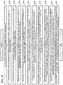
- FIG. 12 is a flow chart illustrating an operational example of the optical communication device 1 in the fourth exemplary embodiment of the present invention.
- FIG. 12 is an example in which the light output unit 10 controls a wavelength output from the light output unit 10 when a channel interval is changed (for example, from 50 GHz to 40 GHz).
- Each LD 101 in the plurality of light output units 10 changes a wavelength of an optical signal to be output based on the change of assignment of a wavelength notified by the control device 3 (S401).
- Each of the optical modulator 102 performs data modulation on an optical signal output from the LD 101, and outputs the signal to the multiplexing unit 13 (S402).
- the multiplexing unit 13 multiplexes optical signals output from the plurality of light output units 10, and outputs a wavelength-multiplexed signal (S403).
- the branching device 22 branches a wavelength-multiplexed signal output from the multiplexing unit 13, and outputs one branched signal to a transmission path, and the other to the coherent detection unit 20 (S404).
- the reference light output unit 14 outputs a reference light having a frequency fo which is a reference for a wavelength of an optical signal output from each light output unit 10 (S405).
- the microwave oscillator 12 changes a frequency F m of a clock signal to be output to the optical comb generator 11 based on a request from the control device 3 (S406).
- the optical comb generator 11 generates, based on a reference light having a wavelength corresponding to a frequency fo output from the reference light output unit 14, a plurality of lights having wavelengths around the frequency fo at a frequency interval of F m (S407).
- the wavelength selection unit 18 inputs, among the plurality of optical signals generated by the optical comb generator 11, a light whose wavelength has been specified by the wavelength switching unit 19 into the coherent detection unit 20 (S408).
- the coherent detection unit 20 outputs a signal (an interference signal) obtained when a wavelength of a light from the wavelength selection unit 18 interferes with a wavelength of a wavelength-multiplexed optical signal from the multiplexing unit 13 to the wavelength shift detection unit 21 (S409).
- the wavelength shift detection unit 21 detects, based on the interference signal, a difference (shift) of wavelengths between at least one optical signal included in a wavelength-multiplexed signal and a light input from the wavelength selection unit 18 (S410).
- the wavelength control unit 16 controls a wavelength of an optical signal output from an LD 101-2 in the light output unit 10-2 in such a way that the difference (shift) of wavelengths detected by the wavelength shift detection unit 21 (S411).
- the fourth exemplary embodiment of the present invention comprises the control device 3 which instructs timing for controlling wavelength to the optical communication device 1, and the optical communication device 1 controls a wavelength of an optical signal output from the light output unit 10 based on the instruction from the control device 3. Accordingly, the optical communication device 1 can control a wavelength by a timing instructed by the control device 3, which makes it possible to flexibly control timing for controlling wavelength.
- a fifth exemplary embodiment of the present invention will be described.
- a computer, a CPU (Central Processing Unit), an MPU (Micro-Processing Unit) and the like of the optical communication device 1 executes a software (a program) which realizes a function described in each of the above-described exemplary embodiments.
- a software a program which realizes a function described in each of the above-described exemplary embodiments.
- the optical communication device 1 acquires a software (a program) which realizes a function of the above-described exemplary embodiments via a variety of storage media or a network, which is non-transitory one, such as a CD-R (Compact Disc Recordable).
- a program which the optical communication device 1 acquires or a storage medium on which the program is stored constitutes the present invention.
- the software (program) may be stored in a predetermined storage unit, which is non-transitory one, included in the optical communication device 1.
- a computer, a CPU, an MPU, or the like of the optical communication device 1 reads a program code from the acquired software (program) and execute the program code.
- the optical communication device 1 executes a processing identical to the processing of the optical communication device 1 in each of the above-described exemplary embodiments.
- the fifth exemplary embodiment of the present invention can be applied to a use such as a program realized by a computer, a CPU, or an MPU of the optical communication device 1.
- An optical communication device comprising:
- the wavelength control unit comprises a comparison unit for comparing the wavelength-multiplexed signal and a light having at least one wavelength among the plurality of lights.
- optical communication device according to Supplementary note 1 or 2, wherein the wavelength control unit comprises:
- the optical communication device comprising a wavelength selection unit for selecting a light having at least one wavelength among a plurality of lights generated by the wavelength generate unit.
- the optical communication device comprising a wavelength switching unit for instructing the at least one wavelength to be selected to the wavelength selection unit.
- optical communication device according to any one of Supplementary notes 1 to 5, wherein the wavelength generate unit comprises:
- the wavelength switching unit notifies, based on at least one wavelength which has been instructed to the wavelength selection unit, a light output unit for controlling a wavelength of an optical signal to be output among the plurality of light output units to the wavelength control unit, and the wavelength control unit controls a wavelength of an optical signal output from the light output unit notified by the wavelength switching unit.
- the optical communication device according to Supplementary note 6 or 7, wherein the wavelength switching unit changes at least one wavelength which is instructed to the wavelength selection unit and a light output unit which is notified to the wavelength control unit in turn, and the wavelength control unit controls a wavelength of an optical signal output from the light output unit notified by the wavelength switching unit in turn.
- An optical communication system comprising:
- control device specifies a light output unit for controlling a wavelength of the optical signal, and notifies the specified light output unit to the optical communication device.
- control device instructs the optical communication device to change a wavelength interval of a plurality of lights generated by the wavelength generation unit when the wavelength interval is changed.
- An optical communication method comprising:
- the optical communication method wherein the wavelength-multiplexed signal and a light having at least one wavelength among the plurality of lights are coherently detected, and a difference between a wavelength of at least one optical signal among the optical signals included in the wavelength-multiplexed signal and a wavelength of at least one light among the plurality of lights is detected based on the coherently detected interference signal.
- the program according to Supplementary note 20 comprising a processing of comparing the wavelength-multiplexed signal and a light having at least one wavelength among the plurality of lights.
Landscapes
- Physics & Mathematics (AREA)
- Electromagnetism (AREA)
- Engineering & Computer Science (AREA)
- Computer Networks & Wireless Communication (AREA)
- Signal Processing (AREA)
- Condensed Matter Physics & Semiconductors (AREA)
- General Physics & Mathematics (AREA)
- Optics & Photonics (AREA)
- Optical Communication System (AREA)
- Semiconductor Lasers (AREA)
Applications Claiming Priority (2)
| Application Number | Priority Date | Filing Date | Title |
|---|---|---|---|
| JP2014065011 | 2014-03-27 | ||
| PCT/JP2015/001578 WO2015146105A1 (fr) | 2014-03-27 | 2015-03-20 | Dispositif de communication optique, système de communication optique, et procédé de transmission optique |
Publications (2)
| Publication Number | Publication Date |
|---|---|
| EP3125447A1 true EP3125447A1 (fr) | 2017-02-01 |
| EP3125447A4 EP3125447A4 (fr) | 2018-03-21 |
Family
ID=54194655
Family Applications (1)
| Application Number | Title | Priority Date | Filing Date |
|---|---|---|---|
| EP15769740.0A Withdrawn EP3125447A4 (fr) | 2014-03-27 | 2015-03-20 | Dispositif de communication optique, système de communication optique, et procédé de transmission optique |
Country Status (5)
| Country | Link |
|---|---|
| US (1) | US10038515B2 (fr) |
| EP (1) | EP3125447A4 (fr) |
| JP (1) | JP6260689B2 (fr) |
| CN (1) | CN106134106B (fr) |
| WO (1) | WO2015146105A1 (fr) |
Families Citing this family (7)
| Publication number | Priority date | Publication date | Assignee | Title |
|---|---|---|---|---|
| CN106134106B (zh) * | 2014-03-27 | 2019-04-16 | 日本电气株式会社 | 光通信设备、光通信系统、光通信方法和非瞬时程序记录介质 |
| WO2016110933A1 (fr) * | 2015-01-05 | 2016-07-14 | 三菱電機株式会社 | Dispositif de communication, et procédé pour commande de fréquence porteuse |
| WO2016161638A1 (fr) * | 2015-04-10 | 2016-10-13 | 华为技术有限公司 | Récepteur cohérent destiné à une estimation de décalage de fréquence et une compensation de source de lumière cohérente, procédé et système |
| CN106572044B (zh) * | 2015-10-10 | 2020-02-07 | 富士通株式会社 | 信道间隔检测装置、方法和系统 |
| US10763959B2 (en) * | 2015-11-20 | 2020-09-01 | Solid, Inc. | Auxiliary device for setting wavelength and method for setting optical wavelength of optical network unit |
| CN115833954B (zh) * | 2021-09-16 | 2025-11-14 | 华为技术有限公司 | 波长校准方法和装置 |
| WO2025248788A1 (fr) * | 2024-05-31 | 2025-12-04 | Ntt株式会社 | Système de transmission et procédé de communication optique |
Family Cites Families (26)
| Publication number | Priority date | Publication date | Assignee | Title |
|---|---|---|---|---|
| JP2772605B2 (ja) * | 1992-10-15 | 1998-07-02 | 国際電信電話株式会社 | 光周波数多重キャリヤ制御装置 |
| JPH08181660A (ja) | 1994-12-22 | 1996-07-12 | Toshiba Corp | 光周波数自動制御方法および光周波数自動制御装置 |
| US5663822A (en) * | 1995-06-14 | 1997-09-02 | Mci Corporation | Optical comb generator using optical white noise source |
| JPH0993194A (ja) * | 1995-09-27 | 1997-04-04 | Nec Corp | 波長安定回路 |
| JP4405598B2 (ja) * | 1996-07-09 | 2010-01-27 | 富士通株式会社 | 信号光出力装置及び信号光出力装置を有する光伝送システム |
| JPH1063350A (ja) * | 1996-08-14 | 1998-03-06 | Kokusai Denshin Denwa Co Ltd <Kdd> | 光周波数安定化装置 |
| JP3047855B2 (ja) * | 1997-04-25 | 2000-06-05 | 日本電気株式会社 | 波長分割多重光送信装置 |
| US6389046B1 (en) * | 1999-04-12 | 2002-05-14 | Agere Systems Guardian Corp. | Method to sense laser array power and wavelength and reduce drift for wavelength selection and stabilization |
| JP2001053379A (ja) * | 1999-08-10 | 2001-02-23 | Hitachi Ltd | 光送信装置 |
| JP2001203643A (ja) | 2000-01-21 | 2001-07-27 | Hitachi Ltd | 波長安定化光送信装置 |
| JP3739987B2 (ja) * | 2000-02-18 | 2006-01-25 | 財団法人神奈川科学技術アカデミー | トモグラフィー装置 |
| US6631019B1 (en) * | 2000-07-05 | 2003-10-07 | Sri International | Reconfigurable multichannel transmitter for dense wavelength division multiplexing (DWDM) optical communication |
| US7061943B2 (en) * | 2000-06-29 | 2006-06-13 | Agility Communications, Inc. | Controller calibration for small form factor sampled grating distributed Bragg reflector laser |
| US6735395B1 (en) * | 2000-09-29 | 2004-05-11 | Futurewei Technologies, Inc. | WDM communication system utilizing WDM optical sources with stabilized wavelengths and light intensity and method for stabilization thereof |
| JP3654170B2 (ja) * | 2000-09-29 | 2005-06-02 | 日本電気株式会社 | 出力監視制御装置および光通信システム |
| GB2381121A (en) * | 2001-06-07 | 2003-04-23 | Univ London | Optical Frequency Synthesizer |
| JP2003060578A (ja) * | 2001-08-13 | 2003-02-28 | Matsushita Electric Ind Co Ltd | 光送信機、光受信機及び光波長多重システム |
| US20030072336A1 (en) * | 2001-09-13 | 2003-04-17 | Spectra-Physics Lasers, Inc. | Miniaturized internal laser stabilizing apparatus with inline output for fiber optic applications |
| US7881620B2 (en) * | 2005-05-04 | 2011-02-01 | Ofs Fitel, Llc | Stabilized optical fiber continuum frequency combs using post-processed highly nonlinear fibers |
| US8285147B2 (en) * | 2008-07-31 | 2012-10-09 | Lg-Ericsson Co., Ltd. | Bulk modulation of multiple wavelengths for generation of CATV optical comb |
| JP5113032B2 (ja) * | 2008-12-24 | 2013-01-09 | 日本電信電話株式会社 | 光送信装置および送信波長設定方法 |
| US8611750B2 (en) * | 2009-10-14 | 2013-12-17 | Futurewei Technologies, Inc. | Wavelength locker for simultaneous control of multiple dense wavelength division multiplexing transmitters |
| JP2012023607A (ja) * | 2010-07-15 | 2012-02-02 | Nec Corp | 波長多重光伝送システムおよび波長間隔設定方法 |
| CN103828146B (zh) * | 2011-07-22 | 2017-07-21 | 因赛特光电子解决方案有限公司 | 从激光器动态自适应地生成波长连续的且规定的波长对时间的扫描的系统和方法 |
| US8989581B2 (en) * | 2012-03-22 | 2015-03-24 | Fujitsu Limited | Wavelength reassignment in optical networks |
| CN106134106B (zh) * | 2014-03-27 | 2019-04-16 | 日本电气株式会社 | 光通信设备、光通信系统、光通信方法和非瞬时程序记录介质 |
-
2015
- 2015-03-20 CN CN201580016853.7A patent/CN106134106B/zh active Active
- 2015-03-20 WO PCT/JP2015/001578 patent/WO2015146105A1/fr not_active Ceased
- 2015-03-20 US US15/127,586 patent/US10038515B2/en active Active
- 2015-03-20 EP EP15769740.0A patent/EP3125447A4/fr not_active Withdrawn
- 2015-03-20 JP JP2016510009A patent/JP6260689B2/ja active Active
Also Published As
| Publication number | Publication date |
|---|---|
| WO2015146105A1 (fr) | 2015-10-01 |
| CN106134106B (zh) | 2019-04-16 |
| US20170134112A1 (en) | 2017-05-11 |
| EP3125447A4 (fr) | 2018-03-21 |
| US10038515B2 (en) | 2018-07-31 |
| JPWO2015146105A1 (ja) | 2017-04-13 |
| JP6260689B2 (ja) | 2018-01-17 |
| CN106134106A (zh) | 2016-11-16 |
Similar Documents
| Publication | Publication Date | Title |
|---|---|---|
| EP3125447A1 (fr) | Dispositif de communication optique, système de communication optique, et procédé de transmission optique | |
| JP6123337B2 (ja) | 光信号処理装置、送信装置、及び光信号処理方法 | |
| US9350479B2 (en) | Apparatus and method for monitoring wavelength tunable optical filter | |
| US9240856B2 (en) | Network system, network apparatus, and method of controlling network | |
| US9143260B2 (en) | Optical transmission system, method of adjusting optical transmission device, and non-transitory computer-readable medium | |
| EP3910820A1 (fr) | Émetteur optique reconfigurable | |
| US20170353265A1 (en) | Spatial Mode Multiplexer With Optical Reference Path | |
| CN104333419A (zh) | 一种可调谐多波长光源及其调制方法 | |
| EP3656069A1 (fr) | Compensation de dispersion chromatique | |
| JP4312698B2 (ja) | 波長多重伝送システムを適用した光伝送ネットワーク設計方法 | |
| US9634787B2 (en) | Optical add-drop multiplexer | |
| EP3317982B1 (fr) | Formation de faisceau optique | |
| US9077470B2 (en) | Optical transmission system using cross phase modulation | |
| WO2017077612A1 (fr) | Dispositif de radar à laser | |
| CA2575595C (fr) | Source de lumiere a longueurs d'ondes multiples et procede de generation d'une lumiere a longueurs d'ondes multiples | |
| US20150139640A1 (en) | Optical monitoring using optical frequency combs | |
| KR101672394B1 (ko) | 다중 파장 수동형 광통신 네트워크를 위한 파장 튜닝 시간 측정 장치 및 방법 | |
| US10230474B1 (en) | Dispersion compensation apparatus and driving method thereof | |
| US12587282B2 (en) | Apparatus and method for maintaining wavelength interval of light sources | |
| JP2011135497A (ja) | 光伝送システム | |
| KR102041714B1 (ko) | 파장 분할 다중화기, 파장분할 다중화 송신기, 파장 분할 다중화 방법 및 파장 분할 다중화 송신 방법 | |
| JPH11326976A (ja) | 等周波数間隔多波長光源 |
Legal Events
| Date | Code | Title | Description |
|---|---|---|---|
| STAA | Information on the status of an ep patent application or granted ep patent |
Free format text: STATUS: THE INTERNATIONAL PUBLICATION HAS BEEN MADE |
|
| PUAI | Public reference made under article 153(3) epc to a published international application that has entered the european phase |
Free format text: ORIGINAL CODE: 0009012 |
|
| STAA | Information on the status of an ep patent application or granted ep patent |
Free format text: STATUS: REQUEST FOR EXAMINATION WAS MADE |
|
| 17P | Request for examination filed |
Effective date: 20160919 |
|
| AK | Designated contracting states |
Kind code of ref document: A1 Designated state(s): AL AT BE BG CH CY CZ DE DK EE ES FI FR GB GR HR HU IE IS IT LI LT LU LV MC MK MT NL NO PL PT RO RS SE SI SK SM TR |
|
| AX | Request for extension of the european patent |
Extension state: BA ME |
|
| DAV | Request for validation of the european patent (deleted) | ||
| DAX | Request for extension of the european patent (deleted) | ||
| A4 | Supplementary search report drawn up and despatched |
Effective date: 20180215 |
|
| RIC1 | Information provided on ipc code assigned before grant |
Ipc: H04B 10/07 20130101ALI20180210BHEP Ipc: H01S 5/0687 20060101ALI20180210BHEP Ipc: H04B 10/572 20130101AFI20180210BHEP Ipc: H04J 14/02 20060101ALI20180210BHEP Ipc: H04J 14/00 20060101ALI20180210BHEP |
|
| STAA | Information on the status of an ep patent application or granted ep patent |
Free format text: STATUS: EXAMINATION IS IN PROGRESS |
|
| 17Q | First examination report despatched |
Effective date: 20190213 |
|
| STAA | Information on the status of an ep patent application or granted ep patent |
Free format text: STATUS: THE APPLICATION IS DEEMED TO BE WITHDRAWN |
|
| 18D | Application deemed to be withdrawn |
Effective date: 20231003 |