EP3125478A1 - Method, device, and system for determining intermediate routing node - Google Patents
Method, device, and system for determining intermediate routing node Download PDFInfo
- Publication number
- EP3125478A1 EP3125478A1 EP15785832.5A EP15785832A EP3125478A1 EP 3125478 A1 EP3125478 A1 EP 3125478A1 EP 15785832 A EP15785832 A EP 15785832A EP 3125478 A1 EP3125478 A1 EP 3125478A1
- Authority
- EP
- European Patent Office
- Prior art keywords
- channel
- routing node
- routing
- fault
- node
- Prior art date
- Legal status (The legal status is an assumption and is not a legal conclusion. Google has not performed a legal analysis and makes no representation as to the accuracy of the status listed.)
- Granted
Links
Images




Classifications
-
- H—ELECTRICITY
- H04—ELECTRIC COMMUNICATION TECHNIQUE
- H04L—TRANSMISSION OF DIGITAL INFORMATION, e.g. TELEGRAPHIC COMMUNICATION
- H04L45/00—Routing or path finding of packets in data switching networks
- H04L45/22—Alternate routing
-
- H—ELECTRICITY
- H04—ELECTRIC COMMUNICATION TECHNIQUE
- H04L—TRANSMISSION OF DIGITAL INFORMATION, e.g. TELEGRAPHIC COMMUNICATION
- H04L41/00—Arrangements for maintenance, administration or management of data switching networks, e.g. of packet switching networks
- H04L41/06—Management of faults, events, alarms or notifications
- H04L41/0654—Management of faults, events, alarms or notifications using network fault recovery
- H04L41/0668—Management of faults, events, alarms or notifications using network fault recovery by dynamic selection of recovery network elements, e.g. replacement by the most appropriate element after failure
-
- H—ELECTRICITY
- H04—ELECTRIC COMMUNICATION TECHNIQUE
- H04L—TRANSMISSION OF DIGITAL INFORMATION, e.g. TELEGRAPHIC COMMUNICATION
- H04L45/00—Routing or path finding of packets in data switching networks
- H04L45/02—Topology update or discovery
-
- H—ELECTRICITY
- H04—ELECTRIC COMMUNICATION TECHNIQUE
- H04L—TRANSMISSION OF DIGITAL INFORMATION, e.g. TELEGRAPHIC COMMUNICATION
- H04L45/00—Routing or path finding of packets in data switching networks
- H04L45/18—Loop-free operations
-
- H—ELECTRICITY
- H04—ELECTRIC COMMUNICATION TECHNIQUE
- H04L—TRANSMISSION OF DIGITAL INFORMATION, e.g. TELEGRAPHIC COMMUNICATION
- H04L45/00—Routing or path finding of packets in data switching networks
- H04L45/28—Routing or path finding of packets in data switching networks using route fault recovery
Definitions
- the present invention relates to the field of communications technologies, and specifically, to a method and apparatus for determining an intermediate routing node, and a system.
- a fault in the network may cause a communication path between a source routing node and a destination routing node to be blocked, resulting in termination of data transmission.
- a fault-tolerant routing technology is generally used, in which a network fault is tolerated by bypassing a fault point and a reliable communication service is provided for a user.
- a management node finds an intermediate routing node I for an affected node pair (S, D).
- the intermediate routing node I needs to meet two conditions: (1) There is no fault in a path from S to I; (2) There is no fault in a path from I to D.
- a message originally sent from S to D is first sent from S to I (a routing phase 1) and then forwarded from I to D (a routing phase 2).
- a message routed from S to D experiences two phases, that is: from S to I and from I to D.
- the message is switched to a new virtual channel when passing the intermediate routing node I and a serial number of the virtual channel needs to be monotonic. For example, a first virtual channel is used in a routing phase 1 and a second virtual channel is used in a routing phase 2.
- a routing deadlock is prevented by using a virtual channel method, which has a relatively high resource requirement.
- n+1 virtual channels need to be used when n intermediate routing nodes are required for use. These virtual channels are not in use if there is no fault, and therefore, resources are severely wasted and network resource utilization is low.
- a fault area can be bypassed with only a small quantity of intermediate routing nodes.
- the system must reserve resources according to a worst case, resulting in severely unbalanced resource utilization and leading to poor system performance.
- Embodiments of the present invention provide a method for determining an intermediate routing node.
- An intermediate routing node that does not have a dependency relationship loop in a channel dependency graph may be determined by verifying, before determining the intermediate routing node, whether the intermediate routing node constitutes a dependency relationship loop in the channel dependency graph.
- to-be-transmitted data may be transferred by using only one intermediate routing node, without requiring that multiple virtual channels be in an idle and ready state. This improves resource utilization of a routing network.
- the embodiments of the present invention further provide a corresponding apparatus and system.
- a first aspect of the present invention provides a method for determining an intermediate routing node, including:
- the adding a channel dependency relationship between a to-be-verified intermediate routing node and the two routing nodes to a channel dependency graph of a routing network in which this fault has not occurred, to enable the channel dependency graph to become an updated channel dependency graph includes:
- the determining at least one intermediate routing node that is used to transfer to-be-transmitted data between the two routing nodes includes:
- the method before the adding a channel dependency relationship between a to-be-verified intermediate routing node and the two routing nodes to a channel dependency graph of a routing network in which this fault has not occurred, to enable the channel dependency graph to become an updated channel dependency graph, the method further includes:
- the method further includes:
- a second aspect of the present invention provides an apparatus for determining an intermediate routing node, including:
- the channel dependency graph update unit includes:
- the first determining unit includes:
- the apparatus further includes:
- the apparatus further includes:
- a third aspect of the present invention provides a routing control system, including: a routing node and a management node, where the routing node is in a communication connection in a manner defined according to a network topology, and there is a communication connection between the management node and any routing node of the routing node; and
- the channel dependency relationship between a to-be-verified intermediate routing node and the two routing nodes is added to a channel dependency graph of a routing network in which this fault has not occurred, to enable the channel dependency graph to become an updated channel dependency graph, where the to-be-verified intermediate routing node is any one of the at least one intermediate routing node, the channel dependency relationship is a combination of channels in which the two routing nodes perform data transmission by using the to-be-verified intermediate routing node, and the channel dependency graph of the routing network in which this fault has not occurred is used to describe a dependency relationship constituted by any two channels in the routing network in which this fault has not occurred, or a combination of a dependency relationship constituted by any two channels in the routing network in which this fault has not occurred and a channel dependency relationship that is established before the fault; and when
- an intermediate routing node that does not have a dependency relationship loop in a channel dependency graph may be determined by verifying, before determining the intermediate routing node, whether the intermediate routing node constitutes a dependency relationship loop in the channel dependency graph.
- to-be-transmitted data may be transferred by using only one intermediate routing node, without requiring that multiple virtual channels be in an idle and ready state. This improves resource utilization of a routing network. Therefore, in a network with same resources as a network in the prior art, a fault-tolerance capability is more powerful and network performance is better in this solution.
- Embodiments of the present invention provide a method for determining an intermediate routing node, in which an intermediate routing node that does not have a dependency relationship loop in a channel dependency graph may be determined by verifying, before determining the intermediate routing node, whether the intermediate routing node constitutes a dependency relationship loop in the channel dependency graph.
- to-be-transmitted data may be transferred by using only one intermediate routing node, without requiring that multiple virtual channels be in an idle and ready state. This improves resource utilization of a routing network.
- the embodiments of the present invention further provide a corresponding apparatus and system. The following provides detailed description separately.
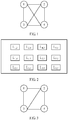
- FIG. 1 is a schematic diagram of an example of a routing network according to an embodiment of the present invention.
- a fully interconnected routing network that includes four routing nodes is used as an example.
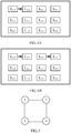
- a channel dependency graph corresponding to FIG. 1 is shown in FIG. 2 .
- the channel dependency graph shown in FIG. 2 may also be understood as an original channel dependency graph.
- the channel dependency graph is defined as follows: Each channel shown in FIG. 1 is denoted by a node in the channel dependency graph, and a symbol L 1,2 in the channel dependency graph denotes a channel from a node 1 to a node 2. It is assumed that there is an arrow between L 1,2 and L 2,4 , and this indicates that the channel L 1,2 depends on the channel L 2,4 .
- the routing node 1 when a communication fault occurs between a routing node 1 and a routing node 4, the routing node 1 cannot directly communicate with the routing node 4.
- a routing node 3 may be used as a final intermediate routing node from the routing node 4 to the routing node 1, and a channel dependency relationship L 4,3 ->L 3,1 from L 4,3 to L 3,1 is added to FIG. 4A .
- FIG. 4B there is still no dependency relationship loop in a channel dependency graph. Therefore, the routing node 3 may be used as a final intermediate routing node from the routing node 4 to the routing node 1.
- a channel dependency relationship L 2,4 ->L 4,3 is added to FIG. 4B .
- an updated channel dependency graph is shown in FIG. 6 . Because there is no dependency relationship loop in the updated channel dependency graph shown in FIG. 6 , it may be determined that the routing node 4 may be used as a final intermediate routing node for communication from the routing node 2 to the routing node 3.
- a channel dependency relationship L 3,1 ->L 1,2 is added to the channel dependency graph in FIG. 6 .
- an updated channel dependency graph is shown in FIG. 7 . It may be found that there is a dependency relationship loop in the updated channel dependency graph in FIG. 7 . Therefore, the routing node 1 cannot be used as an intermediate routing node for communication from the routing node 3 to the routing node 2.
- a channel dependency graph that has a dependency relationship loop does not need to be saved, because no communication dependency graph that includes a dependency relationship loop will be used for next addition of a channel dependency relationship.
- the routing node 4 may be tried again and a channel dependency relationship L 3,4 ->L 4,2 is added to the communication dependency graph in FIG. 6 .
- an updated channel dependency graph is shown in FIG. 8 . Because there is no dependency relationship loop in the channel dependency graph shown in FIG. 8 , it is determined that the routing node 4 may be used as a final intermediate routing node for communication from the routing node 3 to the routing node 2.
- FIG. 9 is a schematic diagram of another embodiment of a routing network according to the embodiments of the present invention.
- six routing nodes are included.
- a routing node 1 in the routing network shown in FIG. 9 can separately perform direct communication with a routing node 5, a routing node 3, and a routing node 4.
- the routing node 1 needs to depend on the routing node 3 or the routing node 4 (in this case, it is assumed that an Up*/Down* routing algorithm is used), and the routing node 2 can perform direct communication with the routing node 3 and the routing node 4.
- FIG. 9 needs to enable any two routing nodes in FIG. 9 to perform communication, and to perform direct communication if direct communication can be performed, or to perform indirect communication by using another routing node if direct communication cannot be performed.
- other routing nodes that are used should be as few as possible. Therefore, the channel dependency graph corresponding to the routing network shown in FIG. 9 is shown in FIG. 10 .
- the routing node 2 is used as a to-be-verified intermediate routing node from the routing node 1 to the routing node 4, a last channel in a communication path between the routing node 1 and the routing node 2 is L 3,2 and the channel L 3,2 may be used as a dependency start channel, and a first channel in a communication path between the routing node 2 and the routing node 4 is L 2,4 and the channel L 2,4 may be used as a dependency end channel. Therefore, a channel dependency relationship L 3,2 -> L 2,4 from the channel L 3,2 to the channel L 2,4 is added to a channel dependency graph in which this fault has not occurred, that is, FIG. 10 . A new dependency relationship is added to the channel dependency graph shown in FIG. 10 to obtain an updated channel dependency graph. There is no dependency relationship loop in the updated channel dependency graph. Therefore, the routing node 2 may be used as a final intermediate routing node between the routing node 1 and the routing node 4.
- a communication path between a source routing node, a to-be-verified intermediate routing node, and a destination routing node is constituted by connecting multiple channels in series.
- Channels from the source routing node to the to-be-verified intermediate routing node are respectively defined as a first channel, a second channel, ..., and a last channel starting from the source routing node, and channels from the to-be-verified intermediate routing node to the destination routing node are respectively defined as a first channel, a second channel, ..., and a last channel starting from the to-be-verified intermediate routing node.
- a process is the same as that described in the foregoing FIG. 1 to FIG. 8 .
- FIG. 9 and FIG. 10 it is only emphasized that a channel dependency graph is determined depending on a communication relationship, between routing nodes, predefined in a routing network. Not every two routing nodes can perform direct communication; however, two routing nodes can depend on another routing node to implement communication.
- an embodiment of a method for determining an intermediate routing node according to the embodiments of the present invention includes:
- the to-be-verified intermediate routing node is any one of the at least one intermediate routing node
- the channel dependency relationship is a combination of channels in which the two routing nodes perform data transmission by using the to-be-verified intermediate routing node
- the channel dependency graph of the routing network in which this fault has not occurred is used to describe a dependency relationship constituted by any two channels in the routing network in which this fault has not occurred, or a combination of a dependency relationship constituted by any two channels in the routing network in which this fault has not occurred and a channel dependency relationship that is established before the fault.
- a routing network has a fault-tolerance capability, recovery does not need to be performed once a fault occurs.
- a channel dependency relationship induced from a communication fault needs to be added to an initial channel dependency graph, and a channel dependency graph to which the channel dependency relationship is already added is an updated channel dependency graph.
- a channel dependency relationship induced from this fault needs to be added to a communication dependency graph that is obtained a channel dependency relationship is added at a previous time.
- the channel dependency graph is defined as follows: each node in a channel dependency graph denotes one channel in a routing network, and a symbol L1,2 in the channel dependency graph denotes one channel. If there is an arrow between L 1,2 and L 2,4 , as shown in FIG. 4A , this indicates that the channel L 1,2 and the channel L 2,4 depend on each other.
- the to-be-verified intermediate routing node determines the to-be-verified intermediate routing node as a final intermediate routing node that is used to transfer the to-be-transmitted data, where the dependency relationship loop is a loop constituted by a channel dependency relationship combination.
- At least one intermediate routing node that is used to transfer to-be-transmitted data between the two routing nodes is determined; a channel dependency relationship between a to-be-verified intermediate routing node and the two routing nodes is added to a channel dependency graph of a routing network in which this fault has not occurred, to enable the channel dependency graph to become an updated channel dependency graph, where the to-be-verified intermediate routing node is any one of the at least one intermediate routing node, the channel dependency relationship is a combination of channels in which the two routing nodes perform data transmission by using the to-be-verified intermediate routing node, and the channel dependency graph of the routing network in which this fault has not occurred is used to describe a channel constituted by any two routing nodes in the routing network in which this fault has not occurred, or a combination of a channel constituted by any two routing nodes in the routing network in which this fault has not occurred and a channel dependency relationship that is established before the fault; and
- an intermediate routing node that does not have a dependency relationship loop in a channel dependency graph may be determined by verifying, before determining the intermediate routing node, whether the intermediate routing node constitutes a dependency relationship loop in the channel dependency graph.
- to-be-transmitted data may be transferred by using only one intermediate routing node, without requiring that multiple virtual channels be in an idle and ready state. This improves resource utilization of a routing network. Therefore, in a network with same resources as a network in the prior art, a fault-tolerance capability is more powerful and network performance is better in this solution.
- the adding a channel dependency relationship between a to-be-verified intermediate routing node and the two routing nodes to a channel dependency graph of a routing network in which this fault has not occurred, to enable the channel dependency graph to become an updated channel dependency graph may include:
- a communication path between a source routing node, a to-be-verified intermediate routing node, and a destination routing node is constituted by connecting multiple channels in series.
- Channels from the source routing node to the to-be-verified intermediate routing node are respectively defined as a first channel, a second channel, ..., and a last channel starting from the source routing node, and channels from the to-be-verified intermediate routing node to the destination routing node are respectively defined as a first channel, a second channel, ..., and a last channel starting from the to-be-verified intermediate routing node.
- a process described in this embodiment of the present invention is a process of adding a line to a channel dependency graph, for example, a process of adding an arrow between the described L 1,2 and L 2,4 in FIG. 1 to FIG. 10 , and details are not described herein.
- the determining at least one intermediate routing node that is used to transfer to-be-transmitted data between the two routing nodes may include:
- a process described in this embodiment of the present invention is a process of step 2 to step 4 that are described in the foregoing FIG. 1 to FIG. 10 , and details are not described herein.
- the method may further include:
- the channel dependency graph of the routing network in which this fault has not occurred and that is described in this embodiment of the present invention is saved upon a previous update of a channel dependency graph and needs only to be directly read, which can improve efficiency in obtaining an updated channel dependency graph.
- the method may further include:
- a source routing node may directly send to-be-transmitted data according to the description information of the final intermediate routing node, and according to this embodiment of the present invention, a routing network needs only communication paths from the source routing node to the final intermediate routing node and from the final intermediate routing node to a destination routing nod, without requiring that another communication path be always in an idle and ready state. This improves resource utilization of the routing network.
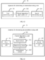
- an embodiment of an apparatus 20 for determining an intermediate routing node includes:
- a first determining unit 201 determines at least one intermediate routing node that is used to transfer to-be-transmitted data between the two routing nodes; a channel dependency graph update unit 202 adds a channel dependency relationship between a to-be-verified intermediate routing node and the two routing nodes to a channel dependency graph of a routing network in which this fault has not occurred, to enable the channel dependency graph to become an updated channel dependency graph, where the to-be-verified intermediate routing node is any one of the at least one intermediate routing node determined by the determining unit, the channel dependency relationship is a combination of channels in which the two routing nodes perform data transmission by using the to-be-verified intermediate routing node, and the channel dependency graph of the routing network in which this fault has not occurred is used to describe a channel constituted by any two routing nodes in the routing network in which this fault has not occurred, or a combination of a channel constituted by any two routing nodes in the
- an intermediate routing node that does not have a dependency relationship loop in a channel dependency graph may be determined by verifying, before determining the intermediate routing node, whether the intermediate routing node constitutes a dependency relationship loop in the channel dependency graph.
- to-be-transmitted data may be transferred by using only one intermediate routing node, without requiring that multiple virtual channels be in an idle and ready state. This improves resource utilization of a routing network. Therefore, in a network with same resources as a network in the prior art, a fault-tolerance capability is more powerful and network performance is better in this solution.
- the channel dependency graph update unit 202 includes:
- the first determining unit 201 includes:
- the apparatus 20 further includes:
- the apparatus 20 further includes:
- FIG. 17 is a schematic structural diagram of an apparatus 20 for determining an intermediate routing node according to an embodiment of the present invention.
- the apparatus 20 for determining an intermediate routing node may include an input device 210, an output device 220, a processor 230, and a memory 240.
- the memory 240 may include a read-only memory and a random access memory, and provides an instruction and data to the processor 230.
- a part of the memory 240 may further include a non-volatile random access memory (NVRAM).
- NVRAM non-volatile random access memory
- the memory 240 stores the following elements: an executable module or a data structure, or a subset thereof, or an extended set thereof:
- the processor 230 performs the following operations by invoking an operation instruction (this operation instruction may be stored in an operating system) stored in the memory 240:
- an apparatus 20 for determining an intermediate routing node verifies whether the intermediate routing node constitutes a dependency relationship loop in a channel dependency graph, so that an intermediate routing node that does not have a dependency relationship loop in the channel dependency graph may be determined, and when a communication fault occurs between two routing nodes, to-be-transmitted data may be transferred by using only one intermediate routing node, without requiring that multiple virtual channels be in an idle and ready state.
- This improves resource utilization of a routing network. Therefore, in a network with same resources as a network in the prior art, a fault-tolerance capability is more powerful and network performance is better in this solution.
- the processor 230 controls an operation of the apparatus 20 for determining an intermediate routing node.
- the processor 230 may also be referred to as a CPU (Central Processing Unit, central processing unit).
- the memory 240 may include a read-only memory and a random access memory, and provides an instruction and data to the processor 230. A part of the memory 240 may further include a non-volatile random access memory (NVRAM).
- NVRAM non-volatile random access memory
- all components of the apparatus 20 for determining an intermediate routing node are coupled together by using a bus system 250, where the bus system 250 may further include a power bus, a control bus, a status signal bus, and the like in addition to a data bus.
- all types of buses are marked as the bus system 250 in FIG. 18 .
- the method disclosed in the embodiments of the present invention may be applied to the processor 230 or implemented by the processor 230.
- the processor 230 may be an integrated circuit chip with a signal processing capability. In an implementation process, steps of the foregoing method may be performed by an integrated logical circuit in hardware or by an instruction in a form of software in the processor 230.
- the foregoing processor 230 may be a general purpose processor, a digital signal processor (DSP), an application-specific integrated circuit (ASIC), a field programmable gate array (FPGA) or another programmable logic device, a discrete gate or a transistor logic device, or a discrete hardware assembly, and may implement or execute the methods, steps, and logical block diagrams that are disclosed in the embodiments of the present invention.
- DSP digital signal processor
- ASIC application-specific integrated circuit
- FPGA field programmable gate array
- the general purpose processor may be a microprocessor or the processor may be any conventional processor or the like. Steps of the method disclosed with reference to the embodiments of the present invention may be directly reflected as being executed by a decoding processor in a form of hardware, or may be executed by using a combination of hardware and software modules in a decoding processor.
- the software module may be located in a mature storage medium in the prior art, such as a random access memory, a flash memory, a read-only memory, a programmable read-only memory or an electrically-erasable programmable memory, or a register.
- the storage medium is located in the memory 240, and the processor 230 reads information from the memory 240 and performs, with reference to hardware thereof, the steps in the foregoing methods.
- the processor 230 may specifically:
- the processor 230 may specifically:
- processor 230 may further:
- the output device 220 may be configured to send description information of the intermediate routing node to the source routing node of the two routing nodes, so that the source routing node sends the to-be-transmitted data to the intermediate routing node.
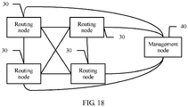
- a routing control system includes: a routing node 30 and a management node 40, where any two routing nodes of the routing node 30 are in a communication connection in a manner defined according to a network topology, and there is a communication connection between the management node 40 and any routing node of the routing node.
- routing nodes 30 are drawn. In practice, there may be many routing nodes 30. It may be understood that not all are drawn in FIG. 18 .
- the management node 40 is configured to: when there is a fault in a communication path between two routing nodes, determine at least one intermediate routing node that is used to transfer to-be-transmitted data between the two routing nodes; add a channel dependency relationship between a to-be-verified intermediate routing node and the two routing nodes to a channel dependency graph of a routing network in which this fault has not occurred, to enable the channel dependency graph to become an updated channel dependency graph, where the to-be-verified intermediate routing node is any one of the at least one intermediate routing node, the channel dependency relationship is a combination of channels in which the two routing nodes perform data transmission by using the to-be-verified intermediate routing node, and the channel dependency graph of the routing network in which this fault has not occurred is used to describe a channel constituted by any two routing nodes in the routing network in which this fault has not occurred, or a combination of a channel constituted by any two routing nodes in the routing network in which this fault has not occurred and a channel dependency relationship that is established before the fault; and
- an intermediate routing node that does not have a dependency relationship loop in a channel dependency graph may be determined by verifying, before determining the intermediate routing node, whether the intermediate routing node constitutes a dependency relationship loop in the channel dependency graph.
- to-be-transmitted data may be transferred by using only one intermediate routing node, without requiring that multiple virtual channels be in an idle and ready state. This improves resource utilization of a routing network. Therefore, in a network with same resources as a network in the prior art, a fault-tolerance capability is more powerful and network performance is better in this solution.
- the program may be stored in a computer readable storage medium.
- the storage medium may include: a ROM, a RAM, a magnetic disk, or an optical disc.
Landscapes
- Engineering & Computer Science (AREA)
- Computer Networks & Wireless Communication (AREA)
- Signal Processing (AREA)
- Data Exchanges In Wide-Area Networks (AREA)
Abstract
Description
- This application claims priority to Chinese Patent Application No.
201410182254.X - The present invention relates to the field of communications technologies, and specifically, to a method and apparatus for determining an intermediate routing node, and a system.
- In a routing network, a fault in the network may cause a communication path between a source routing node and a destination routing node to be blocked, resulting in termination of data transmission. In this case, in the prior art, a fault-tolerant routing technology is generally used, in which a network fault is tolerated by bypassing a fault point and a reliable communication service is provided for a user.
- After a fault occurs in a transmission path between a source node S and a destination node D in a routing network, a management node finds an intermediate routing node I for an affected node pair (S, D). The intermediate routing node I needs to meet two conditions: (1) There is no fault in a path from S to I; (2) There is no fault in a path from I to D. After I is found, a message originally sent from S to D is first sent from S to I (a routing phase 1) and then forwarded from I to D (a routing phase 2).
- In an existing routing network, for ensuring that no routing deadlock occurs, after an intermediate routing node I is added, a message routed from S to D experiences two phases, that is: from S to I and from I to D. In the prior art, to ensure that no routing deadlock occurs after a message passes the intermediate routing node I, the message is switched to a new virtual channel when passing the intermediate routing node I and a serial number of the virtual channel needs to be monotonic. For example, a first virtual channel is used in a
routing phase 1 and a second virtual channel is used in arouting phase 2. - In the prior art, a routing deadlock is prevented by using a virtual channel method, which has a relatively high resource requirement. For example, n+1 virtual channels need to be used when n intermediate routing nodes are required for use. These virtual channels are not in use if there is no fault, and therefore, resources are severely wasted and network resource utilization is low. In addition, in most cases, a fault area can be bypassed with only a small quantity of intermediate routing nodes. However, the system must reserve resources according to a worst case, resulting in severely unbalanced resource utilization and leading to poor system performance.
- Embodiments of the present invention provide a method for determining an intermediate routing node. An intermediate routing node that does not have a dependency relationship loop in a channel dependency graph may be determined by verifying, before determining the intermediate routing node, whether the intermediate routing node constitutes a dependency relationship loop in the channel dependency graph. When a communication fault occurs between two routing nodes, to-be-transmitted data may be transferred by using only one intermediate routing node, without requiring that multiple virtual channels be in an idle and ready state. This improves resource utilization of a routing network. The embodiments of the present invention further provide a corresponding apparatus and system.
- A first aspect of the present invention provides a method for determining an intermediate routing node, including:
- when there is a fault in a communication path between two routing nodes, determining at least one intermediate routing node that is used to transfer to-be-transmitted data between the two routing nodes;
- adding a channel dependency relationship between a to-be-verified intermediate routing node and the two routing nodes to a channel dependency graph of a routing network in which this fault has not occurred, to enable the channel dependency graph to become an updated channel dependency graph, where the to-be-verified intermediate routing node is any one of the at least one intermediate routing node, the channel dependency relationship is a combination of channels in which the two routing nodes perform data transmission by using the to-be-verified intermediate routing node, and the channel dependency graph of the routing network in which this fault has not occurred is used to describe a dependency relationship constituted by any two channels in the routing network in which this fault has not occurred, or a combination of a dependency relationship constituted by any two channels in the routing network in which this fault has not occurred and a channel dependency relationship that is established before the fault; and
- when the updated channel dependency graph does not have a dependency relationship loop, determining the to-be-verified intermediate routing node as a final intermediate routing node that is used to transfer the to-be-transmitted data, where the dependency relationship loop is a loop constituted by a channel dependency relationship combination.
- With reference to the first aspect, in a first possible implementation manner, the adding a channel dependency relationship between a to-be-verified intermediate routing node and the two routing nodes to a channel dependency graph of a routing network in which this fault has not occurred, to enable the channel dependency graph to become an updated channel dependency graph includes:
- searching, according to a transmission direction of the to-be-transmitted data, the channel dependency graph of the routing network in which this fault has not occurred, to find a last channel in a path between a source routing node of the two routing nodes and the to-be-verified intermediate routing node and a first channel in a path between the to-be-verified intermediate routing node and a destination routing node of the two routing nodes;
- determining the last channel in the path between the source routing node and the to-be-verified intermediate routing node as a dependency start channel, and determining the first channel in the path between the to-be-verified intermediate routing node and the destination routing node as a dependency end channel; and
- adding, to the channel dependency graph of the routing network in which this fault has not occurred, a communication dependency relationship that is from the dependency start channel to the dependency end channel, so that the channel dependency graph of the routing network in which this fault has not occurred becomes the updated channel dependency graph.
- With reference to the first aspect or the first possible implementation manner of the first aspect, in a second possible implementation manner, the determining at least one intermediate routing node that is used to transfer to-be-transmitted data between the two routing nodes includes:
- obtaining, as a first information set, information about a routing node in a fault-free communication connection to the source routing node of the two routing nodes;
- obtaining, as a second information set, information about a routing node in a fault-free communication connection to the destination routing node of the two routing nodes, and calculating an intersection set of the first information set and the second information set; and
- determining, as the at least one intermediate routing node, a routing node corresponding to routing node information included in the intersection set.
- With reference to the first aspect or the first possible implementation manner of the first aspect, in a third possible implementation manner, before the adding a channel dependency relationship between a to-be-verified intermediate routing node and the two routing nodes to a channel dependency graph of a routing network in which this fault has not occurred, to enable the channel dependency graph to become an updated channel dependency graph, the method further includes:
- obtaining, as the channel dependency graph of the routing network in which this fault has not occurred, a channel dependency graph that does not include a dependency relationship loop and that is obtained a channel dependency relationship is added at a previous time.
- With reference to the first aspect or the first possible implementation manner of the first aspect, in a fourth possible implementation manner, the method further includes:
- sending description information of the final intermediate routing node to the source routing node of the two routing nodes, so that the source routing node sends the to-be-transmitted data to the final intermediate routing node.
- A second aspect of the present invention provides an apparatus for determining an intermediate routing node, including:
- a first determining unit, configured to: when there is a fault in a communication path between two routing nodes, determine at least one intermediate routing node that is used to transfer to-be-transmitted data between the two routing nodes;
- a channel dependency graph update unit, configured to add a channel dependency relationship between a to-be-verified intermediate routing node and the two routing nodes to a channel dependency graph of a routing network in which this fault has not occurred, to enable the channel dependency graph to become an updated channel dependency graph, where the to-be-verified intermediate routing node is any one of the at least one intermediate routing node determined by the determining unit, the channel dependency relationship is a combination of channels in which the two routing nodes perform data transmission by using the to-be-verified intermediate routing node, and the channel dependency graph of the routing network in which this fault has not occurred is used to describe a dependency relationship constituted by any two channels in the routing network in which this fault has not occurred, or a combination of a dependency relationship constituted by any two channels in the routing network in which this fault has not occurred and a channel dependency relationship that is established before the fault; and
- a second determining unit, configured to: when the updated channel dependency graph updated by the channel dependency graph update unit does not have a dependency relationship loop, determine the to-be-verified intermediate routing node as a final intermediate routing node that is used to transfer the to-be-transmitted data, where the dependency relationship loop is a loop constituted by a channel dependency relationship combination.
- With reference to the second aspect, in a first possible implementation manner, the channel dependency graph update unit includes:
- a search subunit, configured to search, according to a transmission direction of the to-be-transmitted data, the channel dependency graph of the routing network in which this fault has not occurred, to find a last channel in a path between a source routing node of the two routing nodes and the to-be-verified intermediate routing node and a first channel in a path between the to-be-verified intermediate routing node and a destination routing node of the two routing nodes;
- a determining subunit, configured to determine the last channel, found by the search subunit, in the path between the source routing node and the to-be-verified intermediate routing node as a dependency start channel, and determine the first channel, found by the search subunit, in the path between the to-be-verified intermediate routing node and the destination routing node as a dependency end channel; and
- an establishment subunit, configured to add, to the channel dependency graph of the routing network in which this fault has not occurred, a channel dependency relationship that is from the dependency start channel to the dependency end channel, where the dependency start channel and the dependency end channel are determined by the determining subunit, so that the channel dependency graph of the routing network in which this fault has not occurred becomes the updated channel dependency graph.
- With reference to the second aspect or the first possible implementation manner of the second aspect, in a second possible implementation manner, the first determining unit includes:
- a first obtaining subunit, configured to obtain, as a first information set, information about a routing node in a fault-free communication connection to the source routing node of the two routing nodes;
- a second obtaining subunit, configured to obtain, as a second information set, information about a routing node in a fault-free communication connection to the destination routing node of the two routing nodes;
- a calculation subunit, configured to calculate an intersection set of the first information set obtained by the first obtaining subunit and the second information set obtained by the second obtaining subunit; and
- a determining subunit, configured to determine, as the at least one intermediate routing node, a routing node corresponding to routing node information included in the intersection set calculated by the calculation subunit.
- With reference to the second aspect or the first possible implementation manner of the second aspect, in a third possible implementation manner, the apparatus further includes:
- an obtaining unit, configured to: before the channel dependency graph update unit updates the channel dependency graph of the routing network in which this fault has not occurred, obtain, as the channel dependency graph of the routing network in which this fault has not occurred, a channel dependency graph that does not include a dependency relationship loop and that is obtained a channel dependency relationship is added at a previous time.
- With reference to the second aspect or the first possible implementation manner of the second aspect, in a fourth possible implementation manner, the apparatus further includes:
- a sending unit, configured to send description information of the final intermediate routing node determined by the second determining unit to the source routing node of the two routing nodes, so that the source routing node sends the to-be-transmitted data to the final intermediate routing node.
- A third aspect of the present invention provides a routing control system, including: a routing node and a management node, where the routing node is in a communication connection in a manner defined according to a network topology, and there is a communication connection between the management node and any routing node of the routing node; and
- the management node is configured to: when there is a fault in a communication path between two routing nodes, determine at least one intermediate routing node that is used to transfer to-be-transmitted data between the two routing nodes; add a channel dependency relationship between a to-be-verified intermediate routing node and the two routing nodes to a channel dependency graph of a routing network in which this fault has not occurred, to enable the channel dependency graph to become an updated channel dependency graph, where the to-be-verified intermediate routing node is any one of the at least one intermediate routing node, the channel dependency relationship is a combination of channels in which the two routing nodes perform data transmission by using the to-be-verified intermediate routing node, and the channel dependency graph of the routing network in which this fault has not occurred is used to describe a channel constituted by any two routing nodes in the routing network in which this fault has not occurred, or a combination of a channel constituted by any two routing nodes in the routing network in which this fault has not occurred and a channel dependency relationship that is established before the fault; and when the updated channel dependency graph does not have a dependency relationship loop, determine the to-be-verified intermediate routing node as a final intermediate routing node that is used to transfer the to-be-transmitted data, where the dependency relationship loop is a loop constituted by a channel dependency relationship combination.
- In the embodiments of the present invention, when there is a fault in a communication path between two routing nodes, at least one intermediate routing node that is used to transfer to-be-transmitted data between the two routing nodes is determined; a channel dependency relationship between a to-be-verified intermediate routing node and the two routing nodes is added to a channel dependency graph of a routing network in which this fault has not occurred, to enable the channel dependency graph to become an updated channel dependency graph, where the to-be-verified intermediate routing node is any one of the at least one intermediate routing node, the channel dependency relationship is a combination of channels in which the two routing nodes perform data transmission by using the to-be-verified intermediate routing node, and the channel dependency graph of the routing network in which this fault has not occurred is used to describe a dependency relationship constituted by any two channels in the routing network in which this fault has not occurred, or a combination of a dependency relationship constituted by any two channels in the routing network in which this fault has not occurred and a channel dependency relationship that is established before the fault; and when the updated channel dependency graph does not have a dependency relationship loop, the to-be-verified intermediate routing node is determined as an intermediate routing node that is used to transfer the to-be-transmitted data, where the dependency relationship loop is a loop constituted by a channel dependency relationship combination of a routing node. In comparison with the prior art in which data transfer needs to depend on multiple virtual channels to prevent a routing deadlock, according to the method provided in the embodiments of the present invention, an intermediate routing node that does not have a dependency relationship loop in a channel dependency graph may be determined by verifying, before determining the intermediate routing node, whether the intermediate routing node constitutes a dependency relationship loop in the channel dependency graph. When a communication fault occurs between two routing nodes, to-be-transmitted data may be transferred by using only one intermediate routing node, without requiring that multiple virtual channels be in an idle and ready state. This improves resource utilization of a routing network. Therefore, in a network with same resources as a network in the prior art, a fault-tolerance capability is more powerful and network performance is better in this solution.
- To describe the technical solutions in the embodiments of the present invention more clearly, the following briefly describes the accompanying drawings required for describing the embodiments. Apparently, the accompanying drawings in the following description show merely some embodiments of the present invention, and a person skilled in the art may still derive other drawings from these accompanying drawings without creative efforts.
-
FIG. 1 is a schematic diagram of an embodiment of a method for determining an intermediate routing node according to the embodiments of the present invention; -
FIG. 2 is a schematic diagram of another embodiment of a method for determining an intermediate routing node according to the embodiments of the present invention; -
FIG. 3 is a schematic diagram of another embodiment of a method for determining an intermediate routing node according to the embodiments of the present invention; -
FIG. 4A is a schematic diagram of another embodiment of a method for determining an intermediate routing node according to the embodiments of the present invention; -
FIG. 4B is a schematic diagram of another embodiment of a method for determining an intermediate routing node according to the embodiments of the present invention; -
FIG. 5 is a schematic diagram of another embodiment of a method for determining an intermediate routing node according to the embodiments of the present invention; -
FIG. 6 is a schematic diagram of another embodiment of a method for determining an intermediate routing node according to the embodiments of the present invention; -
FIG. 7 is a schematic diagram of another embodiment of a method for determining an intermediate routing node according to the embodiments of the present invention; -
FIG. 8 is a schematic diagram of another embodiment of a method for determining an intermediate routing node according to the embodiments of the present invention; -
FIG. 9 is a schematic diagram of another embodiment of a method for determining an intermediate routing node according to the embodiments of the present invention; -
FIG. 10 is a schematic diagram of an embodiment of an apparatus for determining an intermediate routing node according to the embodiments of the present invention; -
FIG. 11 is a schematic diagram of an embodiment of a method for determining an intermediate routing node according to the embodiments of the present invention; -
FIG. 12 is a schematic diagram of an embodiment of an apparatus for determining an intermediate routing node according to the embodiments of the present invention; -
FIG. 13 is a schematic diagram of another embodiment of an apparatus for determining an intermediate routing node according to the embodiments of the present invention; -
FIG. 14 is a schematic diagram of another embodiment of an apparatus for determining an intermediate routing node according to the embodiments of the present invention; -
FIG. 15 is a schematic diagram of another embodiment of an apparatus for determining an intermediate routing node according to the embodiments of the present invention; -
FIG. 16 is a schematic diagram of another embodiment of an apparatus for determining an intermediate routing node according to the embodiments of the present invention; -
FIG. 17 is a schematic diagram of another embodiment of an apparatus for determining an intermediate routing node according to the embodiments of the present invention; and -
FIG. 18 is a schematic diagram of an embodiment of a routing control system according to the embodiments of the present invention. - Embodiments of the present invention provide a method for determining an intermediate routing node, in which an intermediate routing node that does not have a dependency relationship loop in a channel dependency graph may be determined by verifying, before determining the intermediate routing node, whether the intermediate routing node constitutes a dependency relationship loop in the channel dependency graph. When a communication fault occurs between two routing nodes, to-be-transmitted data may be transferred by using only one intermediate routing node, without requiring that multiple virtual channels be in an idle and ready state. This improves resource utilization of a routing network. The embodiments of the present invention further provide a corresponding apparatus and system. The following provides detailed description separately.
- The following clearly and completely describes the technical solutions in the embodiments of the present invention with reference to the accompanying drawings in the embodiments of the present invention. Apparently, the described embodiments are merely some but not all of the embodiments of the present invention. All other embodiments obtained by a person skilled in the art based on the embodiments of the present invention without creative efforts shall fall within the protection scope of the present invention.
- As shown in
FIG. 1, FIG. 1 is a schematic diagram of an example of a routing network according to an embodiment of the present invention. In this embodiment of the present invention, a fully interconnected routing network that includes four routing nodes is used as an example. When there is no fault in the routing network, because any two routing nodes in the fully interconnected routing network shown inFIG. 1 may directly transmit data, data transmission between any two routing nodes does not need to depend on another routing node for forwarding, and therefore, there is no channel dependency relationship. A channel dependency graph corresponding toFIG. 1 is shown inFIG. 2 . The channel dependency graph shown inFIG. 2 may also be understood as an original channel dependency graph. - The channel dependency graph is defined as follows: Each channel shown in
FIG. 1 is denoted by a node in the channel dependency graph, and a symbol L1,2 in the channel dependency graph denotes a channel from anode 1 to anode 2. It is assumed that there is an arrow between L1,2 and L2,4, and this indicates that the channel L1,2 depends on the channel L2,4. - As shown in
FIG. 2 , there is no channel dependency relationship in a current channel dependency graph. - As shown in
FIG. 3 , when a communication fault occurs between arouting node 1 and arouting node 4, therouting node 1 cannot directly communicate with therouting node 4. - To transmit a message from the
routing node 1 to therouting node 4 if there is a fault, main steps of this embodiment of the present invention are as follows: - Step 1: Construct a channel dependency graph, as shown in
FIG. 2 . - Step 2: Find a set Sr={2, 3} of all routing nodes that can be reached from the
routing node 1 in any path. - Step 3: Find a set Ds={2, 3} of all routing nodes that can reach the
destination routing node 4 in any path. - Step 4: Calculate an intersection set Isd={2, 3} of Sr and Ds, so that it may be determined that intermediate routing nodes that are used to transfer to-be-transmitted data between the
routing nodes - Step 5: First, select the
routing node 2 as a to-be-verified intermediate routing node. Hence, a communication path from therouting node 1 to therouting node 4 is 1->2->4, that is, a communication path between therouting node 1 and therouting node 4 is constituted by connecting the channel L1,2 and the channel L2,4 in series. Channels from the source routing node to the to-be-verified intermediate routing node are respectively defined as a first channel, a second channel, ..., and a last channel starting from the source routing node, and channels from the to-be-verified intermediate routing node to the destination routing node are respectively defined as a first channel, a second channel, ..., and a last channel starting from the to-be-verified intermediate routing node. In this way, in the communication path from therouting node 1 to therouting node 4, a last channel in a communication path from therouting node 1 to therouting node 2 is L1,2 and L1,2 may be used as a dependency start channel. A first channel in a communication path from therouting node 2 to therouting node 4 is L2,4 and L2,4 may be used as a dependency end channel. Therefore, a channel dependency relationship L1,2->L2,4 from L1,2 to L2,4 is added to the channel dependency graph, that is,FIG. 2 . As shown inFIG. 4A , a corresponding side is added to achannel dependency graph 2. It can be found that there is no dependency relationship loop inFIG. 4A in this case. Therefore, therouting node 2 is used as a final intermediate routing node for communication from therouting node 1 to thenode 4. - Similarly, it may be obtained by means of calculation that a
routing node 3 may be used as a final intermediate routing node from therouting node 4 to therouting node 1, and a channel dependency relationship L4,3->L3,1 from L4,3 to L3,1 is added toFIG. 4A . As shown inFIG. 4B , there is still no dependency relationship loop in a channel dependency graph. Therefore, therouting node 3 may be used as a final intermediate routing node from therouting node 4 to therouting node 1. - After a communication fault occurs between the
routing node 1 and therouting node 4, in this case, if a fault also occurs in communication between therouting node 2 and therouting node 3, as shown inFIG. 5 , to transmit a message from therouting node 2 to therouting node 3 in a fault case, a channel dependency relationship between therouting node 2 and therouting node 3 with presence of a communication fault may be added to the channel dependency graph inFIG. 4B , and the foregoingstep 2,step 3, andstep 4 may be repeated. Finally, a set Isd={1,4} of routing nodes that may be used as intermediate routing nodes is obtained. When therouting node 4 is selected as a to-be-verified intermediate routing node, in this case, a channel dependency relationship L2,4->L4,3 is added toFIG. 4B . In this case, an updated channel dependency graph is shown inFIG. 6 . Because there is no dependency relationship loop in the updated channel dependency graph shown inFIG. 6 , it may be determined that therouting node 4 may be used as a final intermediate routing node for communication from therouting node 2 to therouting node 3. - To transmit a message from the
routing node 3 to therouting node 2, if therouting node 1 is selected as a to-be-verified intermediate routing node, a channel dependency relationship L3,1->L1,2 is added to the channel dependency graph inFIG. 6 . In this case, an updated channel dependency graph is shown inFIG. 7 . It may be found that there is a dependency relationship loop in the updated channel dependency graph inFIG. 7 . Therefore, therouting node 1 cannot be used as an intermediate routing node for communication from therouting node 3 to therouting node 2. In addition, a channel dependency graph that has a dependency relationship loop does not need to be saved, because no communication dependency graph that includes a dependency relationship loop will be used for next addition of a channel dependency relationship. Then, therouting node 4 may be tried again and a channel dependency relationship L3,4->L4,2 is added to the communication dependency graph inFIG. 6 . In this case, an updated channel dependency graph is shown inFIG. 8 . Because there is no dependency relationship loop in the channel dependency graph shown inFIG. 8 , it is determined that therouting node 4 may be used as a final intermediate routing node for communication from therouting node 3 to therouting node 2. - Referring to
FIG. 9, FIG. 9 is a schematic diagram of another embodiment of a routing network according to the embodiments of the present invention. In this embodiment of the present invention, for example, six routing nodes are included. When there is no fault in the routing network shown inFIG. 9 , arouting node 1 in the routing network shown inFIG. 9 can separately perform direct communication with arouting node 5, arouting node 3, and arouting node 4. However, in communication with arouting node 2, therouting node 1 needs to depend on therouting node 3 or the routing node 4 (in this case, it is assumed that an Up*/Down* routing algorithm is used), and therouting node 2 can perform direct communication with therouting node 3 and therouting node 4. A channel dependency graph corresponding toFIG. 9 needs to enable any two routing nodes inFIG. 9 to perform communication, and to perform direct communication if direct communication can be performed, or to perform indirect communication by using another routing node if direct communication cannot be performed. In addition, when indirect communication is performed, other routing nodes that are used should be as few as possible. Therefore, the channel dependency graph corresponding to the routing network shown inFIG. 9 is shown inFIG. 10 . - For the routing networks shown in
FIG. 9 and FIG. 10 , when a communication fault occurs between therouting node 1 and therouting node 4, a set Sr={2, 3, 5, 6} of all routing nodes that can reach therouting node 1 in any path is found, and a set D={2, 3, 6} of all routing nodes that can reach therouting node 4 in any path is found, and an intersection set Is={2, 3, 6} of Sr and Ds is obtained by means of calculation. Therefore, it may be further determined that intermediate routing nodes that are used to transfer to-be-transmitted data are the routingnode 2, therouting node 3, or therouting node 6. It is assumed that therouting node 2 is used as a to-be-verified intermediate routing node from therouting node 1 to therouting node 4, a last channel in a communication path between therouting node 1 and therouting node 2 is L3,2 and the channel L3,2 may be used as a dependency start channel, and a first channel in a communication path between therouting node 2 and therouting node 4 is L2,4 and the channel L2,4 may be used as a dependency end channel. Therefore, a channel dependency relationship L3,2-> L2,4 from the channel L3,2 to the channel L2,4 is added to a channel dependency graph in which this fault has not occurred, that is,FIG. 10 . A new dependency relationship is added to the channel dependency graph shown inFIG. 10 to obtain an updated channel dependency graph. There is no dependency relationship loop in the updated channel dependency graph. Therefore, therouting node 2 may be used as a final intermediate routing node between therouting node 1 and therouting node 4. - In this embodiment of the present invention, a communication path between a source routing node, a to-be-verified intermediate routing node, and a destination routing node is constituted by connecting multiple channels in series. Channels from the source routing node to the to-be-verified intermediate routing node are respectively defined as a first channel, a second channel, ..., and a last channel starting from the source routing node, and channels from the to-be-verified intermediate routing node to the destination routing node are respectively defined as a first channel, a second channel, ..., and a last channel starting from the to-be-verified intermediate routing node.
- In this embodiment of the present invention, when there is a fault between the
routing node 1 and therouting node 4 and there is also a fault between therouting node 2 and therouting node 3, a process is the same as that described in the foregoingFIG. 1 to FIG. 8 . InFIG. 9 and FIG. 10 , it is only emphasized that a channel dependency graph is determined depending on a communication relationship, between routing nodes, predefined in a routing network. Not every two routing nodes can perform direct communication; however, two routing nodes can depend on another routing node to implement communication. - Referring to
FIG. 11 , an embodiment of a method for determining an intermediate routing node according to the embodiments of the present invention includes: - 101. When there is a fault in a communication path between two routing nodes, determine at least one intermediate routing node that is used to transfer to-be-transmitted data between the two routing nodes.
- 102. Add a channel dependency relationship between a to-be-verified intermediate routing node and the two routing nodes to a channel dependency graph of a routing network in which this fault has not occurred, to enable the channel dependency graph to become an updated channel dependency graph.
- The to-be-verified intermediate routing node is any one of the at least one intermediate routing node, the channel dependency relationship is a combination of channels in which the two routing nodes perform data transmission by using the to-be-verified intermediate routing node, and the channel dependency graph of the routing network in which this fault has not occurred is used to describe a dependency relationship constituted by any two channels in the routing network in which this fault has not occurred, or a combination of a dependency relationship constituted by any two channels in the routing network in which this fault has not occurred and a channel dependency relationship that is established before the fault.
- Because a routing network has a fault-tolerance capability, recovery does not need to be performed once a fault occurs. After the routing network becomes faulty for the first time, a channel dependency relationship induced from a communication fault needs to be added to an initial channel dependency graph, and a channel dependency graph to which the channel dependency relationship is already added is an updated channel dependency graph.
- If it is not the first time that the routing network becomes faulty, a channel dependency relationship induced from this fault needs to be added to a communication dependency graph that is obtained a channel dependency relationship is added at a previous time.
- The channel dependency graph is defined as follows: each node in a channel dependency graph denotes one channel in a routing network, and a symbol L1,2 in the channel dependency graph denotes one channel. If there is an arrow between L1,2 and L2,4, as shown in
FIG. 4A , this indicates that the channel L1,2 and the channel L2,4 depend on each other. - 103. When the updated channel dependency graph does not have a dependency relationship loop, determine the to-be-verified intermediate routing node as a final intermediate routing node that is used to transfer the to-be-transmitted data, where the dependency relationship loop is a loop constituted by a channel dependency relationship combination.
- In this embodiment of the present invention, when there is a fault in a communication path between two routing nodes, at least one intermediate routing node that is used to transfer to-be-transmitted data between the two routing nodes is determined; a channel dependency relationship between a to-be-verified intermediate routing node and the two routing nodes is added to a channel dependency graph of a routing network in which this fault has not occurred, to enable the channel dependency graph to become an updated channel dependency graph, where the to-be-verified intermediate routing node is any one of the at least one intermediate routing node, the channel dependency relationship is a combination of channels in which the two routing nodes perform data transmission by using the to-be-verified intermediate routing node, and the channel dependency graph of the routing network in which this fault has not occurred is used to describe a channel constituted by any two routing nodes in the routing network in which this fault has not occurred, or a combination of a channel constituted by any two routing nodes in the routing network in which this fault has not occurred and a channel dependency relationship that is established before the fault; and when the updated channel dependency graph does not have a dependency relationship loop, the to-be-verified intermediate routing node is determined as a final intermediate routing node that is used to transfer the to-be-transmitted data, where the dependency relationship loop is a loop constituted by a channel dependency relationship combination. In comparison with the prior art in which data transfer needs to depend on multiple virtual channels to prevent a routing deadlock, according to the method provided in the embodiments of the present invention, an intermediate routing node that does not have a dependency relationship loop in a channel dependency graph may be determined by verifying, before determining the intermediate routing node, whether the intermediate routing node constitutes a dependency relationship loop in the channel dependency graph. When a communication fault occurs between two routing nodes, to-be-transmitted data may be transferred by using only one intermediate routing node, without requiring that multiple virtual channels be in an idle and ready state. This improves resource utilization of a routing network. Therefore, in a network with same resources as a network in the prior art, a fault-tolerance capability is more powerful and network performance is better in this solution.
- Optionally, based on the embodiment corresponding to
FIG. 11 , in another embodiment of a method for determining an intermediate routing node according to the embodiments of the present invention, the adding a channel dependency relationship between a to-be-verified intermediate routing node and the two routing nodes to a channel dependency graph of a routing network in which this fault has not occurred, to enable the channel dependency graph to become an updated channel dependency graph may include: - searching, according to a transmission direction of the to-be-transmitted data, the channel dependency graph of the routing network in which this fault has not occurred, to find a last channel in a path between a source routing node of the two routing nodes and the to-be-verified intermediate routing node and a first channel in a path between the to-be-verified intermediate routing node and a destination routing node of the two routing nodes;
- determining the last channel in the path between the source routing node and the to-be-verified intermediate routing node as a dependency start channel, and determining the first channel in the path between the to-be-verified intermediate routing node and the destination routing node as a dependency end channel; and
- adding, to the channel dependency graph of the routing network in which this fault has not occurred, a communication dependency relationship that is from the dependency start channel to the dependency end channel, so that the channel dependency graph of the routing network in which this fault has not occurred becomes the updated channel dependency graph.
- In this embodiment of the present invention, a communication path between a source routing node, a to-be-verified intermediate routing node, and a destination routing node is constituted by connecting multiple channels in series. Channels from the source routing node to the to-be-verified intermediate routing node are respectively defined as a first channel, a second channel, ..., and a last channel starting from the source routing node, and channels from the to-be-verified intermediate routing node to the destination routing node are respectively defined as a first channel, a second channel, ..., and a last channel starting from the to-be-verified intermediate routing node.
- A process described in this embodiment of the present invention is a process of adding a line to a channel dependency graph, for example, a process of adding an arrow between the described L1,2 and L2,4 in
FIG. 1 to FIG. 10 , and details are not described herein. - Optionally, based on the embodiment corresponding to
FIG. 11 or the optional embodiment corresponding toFIG. 11 , in another embodiment of a method for determining an intermediate routing node according to the embodiments of the present invention, the determining at least one intermediate routing node that is used to transfer to-be-transmitted data between the two routing nodes may include: - obtaining, as a first information set, information about a routing node in a fault-free communication connection to the source routing node of the two routing nodes;
- obtaining, as a second information set, information about a routing node in a fault-free communication connection to the destination routing node of the two routing nodes, and calculating an intersection set of the first information set and the second information set; and
- determining, as the at least one intermediate routing node, a routing node corresponding to routing node information included in the intersection set.
- A process described in this embodiment of the present invention is a process of
step 2 to step 4 that are described in the foregoingFIG. 1 to FIG. 10 , and details are not described herein. - Optionally, based on the embodiment corresponding to
FIG. 11 or the optional embodiment corresponding toFIG. 11 , in another embodiment of a method for determining an intermediate routing node according to the embodiments of the present invention, before the adding a channel dependency relationship between a to-be-verified intermediate routing node and the two routing nodes to a channel dependency graph of a routing network in which this fault has not occurred, to enable the channel dependency graph to become an updated channel dependency graph, the method may further include: - obtaining, as the channel dependency graph of the routing network in which this fault has not occurred, a channel dependency graph that does not include a dependency relationship loop and that is obtained a channel dependency relationship is added at a previous time.
- The channel dependency graph of the routing network in which this fault has not occurred and that is described in this embodiment of the present invention is saved upon a previous update of a channel dependency graph and needs only to be directly read, which can improve efficiency in obtaining an updated channel dependency graph.
- Optionally, based on the embodiment corresponding to
FIG. 11 or the optional embodiment corresponding toFIG. 11 , in another embodiment of a method for determining an intermediate routing node according to the embodiments of the present invention, the method may further include: - sending description information of the final intermediate routing node to the source routing node of the two routing nodes, so that the source routing node sends the to-be-transmitted data to the final intermediate routing node.
- In this embodiment of the present invention, after obtaining description information of a final intermediate routing node, a source routing node may directly send to-be-transmitted data according to the description information of the final intermediate routing node, and according to this embodiment of the present invention, a routing network needs only communication paths from the source routing node to the final intermediate routing node and from the final intermediate routing node to a destination routing nod, without requiring that another communication path be always in an idle and ready state. This improves resource utilization of the routing network.
- Referring to
FIG. 12 , an embodiment of anapparatus 20 for determining an intermediate routing node according to the embodiments of the present invention includes: - a first determining
unit 201, configured to: when there is a fault in a communication path between two routing nodes, determine at least one intermediate routing node that is used to transfer to-be-transmitted data between the two routing nodes; - a channel dependency
graph update unit 202, configured to add a channel dependency relationship between a to-be-verified intermediate routing node and the two routing nodes to a channel dependency graph of a routing network in which this fault has not occurred, to enable the channel dependency graph to become an updated channel dependency graph, where the to-be-verified intermediate routing node is any one of the at least one intermediate routing node determined by the determining unit, the channel dependency relationship is a combination of channels in which the two routing nodes perform data transmission by using the to-be-verified intermediate routing node, and the channel dependency graph of the routing network in which this fault has not occurred is used to describe a channel constituted by any two routing nodes in the routing network in which this fault has not occurred, or a combination of a channel constituted by any two routing nodes in the routing network in which this fault has not occurred and a channel dependency relationship that is established before the fault; and - a second determining
unit 203, configured to: when the updated channel dependency graph updated by the channel dependencygraph update unit 202 does not have a dependency relationship loop, determine the to-be-verified intermediate routing node as a final intermediate routing node that is used to transfer the to-be-transmitted data, where the dependency relationship loop is a loop constituted by a channel dependency relationship combination. - In this embodiment of the present invention, when there is a fault in a communication path between two routing nodes, a first determining unit 201 determines at least one intermediate routing node that is used to transfer to-be-transmitted data between the two routing nodes; a channel dependency graph update unit 202 adds a channel dependency relationship between a to-be-verified intermediate routing node and the two routing nodes to a channel dependency graph of a routing network in which this fault has not occurred, to enable the channel dependency graph to become an updated channel dependency graph, where the to-be-verified intermediate routing node is any one of the at least one intermediate routing node determined by the determining unit, the channel dependency relationship is a combination of channels in which the two routing nodes perform data transmission by using the to-be-verified intermediate routing node, and the channel dependency graph of the routing network in which this fault has not occurred is used to describe a channel constituted by any two routing nodes in the routing network in which this fault has not occurred, or a combination of a channel constituted by any two routing nodes in the routing network in which this fault has not occurred and a channel dependency relationship that is established before the fault; and when the updated channel dependency graph updated by the channel dependency graph update unit 202 does not have a dependency relationship loop, a second determining unit 203 determines the to-be-verified intermediate routing node as a final intermediate routing node that is used to transfer the to-be-transmitted data, where the dependency relationship loop is a loop constituted by a channel dependency relationship combination. In comparison with the prior art in which data transfer needs to depend on multiple virtual channels to prevent a routing deadlock, according to the apparatus provided in this embodiment of the present invention, an intermediate routing node that does not have a dependency relationship loop in a channel dependency graph may be determined by verifying, before determining the intermediate routing node, whether the intermediate routing node constitutes a dependency relationship loop in the channel dependency graph. When a communication fault occurs between two routing nodes, to-be-transmitted data may be transferred by using only one intermediate routing node, without requiring that multiple virtual channels be in an idle and ready state. This improves resource utilization of a routing network. Therefore, in a network with same resources as a network in the prior art, a fault-tolerance capability is more powerful and network performance is better in this solution.
- Optionally, based on the embodiment corresponding to
FIG. 12 , referring toFIG. 13 , in another embodiment of theapparatus 20 for determining an intermediate routing node according to the embodiments of the present invention, the channel dependencygraph update unit 202 includes: - a
search subunit 2021, configured to search, according to a transmission direction of the to-be-transmitted data, the channel dependency graph of the routing network in which this fault has not occurred, to find a last channel in a path between a source routing node of the two routing nodes and the to-be-verified intermediate routing node and a first channel in a path between the to-be-verified intermediate routing node and a destination routing node of the two routing nodes; - a determining
subunit 2022, configured to determine the last channel, found by thesearch subunit 2021, in the path between the source routing node and the to-be-verified intermediate routing node as a dependency start channel, and determine the first channel, found by thesearch subunit 2021, in the path between the to-be-verified intermediate routing node and the destination routing node as a dependency end channel; and - an
establishment subunit 2023, configured to add, to the channel dependency graph of the routing network in which this fault has not occurred, a channel dependency relationship that is from the dependency start channel to the dependency end channel, where the dependency start channel and the dependency end channel are determined by the determiningsubunit 2022, so that the channel dependency graph of the routing network in which this fault has not occurred becomes the updated channel dependency graph. - Optionally, based on the embodiment corresponding to
FIG. 10 , referring toFIG. 14 , in another embodiment of theapparatus 20 for determining an intermediate routing node according to the embodiments of the present invention, the first determiningunit 201 includes: - a first obtaining
subunit 2011, configured to obtain, as a first information set, information about a routing node in a fault-free communication connection to the source routing node of the two routing nodes; - a second obtaining
subunit 2012, configured to obtain, as a second information set, information about a routing node in a fault-free communication connection to the destination routing node of the two routing nodes; - a
calculation subunit 2013, configured to calculate an intersection set of the first information set obtained by the first obtainingsubunit 2011 and the second information set obtained by the second obtainingsubunit 2012; and - a determining
subunit 2014, configured to determine, as the at least one intermediate routing node, a routing node corresponding to routing node information included in the intersection set calculated by thecalculation subunit 2013. - Optionally, based on the embodiment corresponding to
FIG. 12 , referring toFIG. 15 , in another embodiment of theapparatus 20 for determining an intermediate routing node according to the embodiments of the present invention, theapparatus 20 further includes: - an obtaining
unit 204, configured to: before the channel dependencygraph update unit 202 updates the channel dependency graph of the routing network in which this fault has not occurred, obtain, as the channel dependency graph of the routing network in which this fault has not occurred, a channel dependency graph that does not include a dependency relationship loop and that is obtained a channel dependency relationship is added at a previous time. - Optionally, based on the embodiment corresponding to
FIG. 12 , referring toFIG. 16 , in another embodiment of theapparatus 20 for determining an intermediate routing node according to the embodiments of the present invention, theapparatus 20 further includes: - a sending
unit 205, configured to send description information of the final intermediate routing node determined by the second determiningunit 203 to the source routing node of the two routing nodes, so that the source routing node sends the to-be-transmitted data to the final intermediate routing node. -
FIG. 17 is a schematic structural diagram of anapparatus 20 for determining an intermediate routing node according to an embodiment of the present invention. Theapparatus 20 for determining an intermediate routing node may include aninput device 210, anoutput device 220, aprocessor 230, and amemory 240. - The
memory 240 may include a read-only memory and a random access memory, and provides an instruction and data to theprocessor 230. A part of thememory 240 may further include a non-volatile random access memory (NVRAM). - The
memory 240 stores the following elements: an executable module or a data structure, or a subset thereof, or an extended set thereof: - operation instruction: including various operation instructions and used to implement various operations; and
- operating system: including various system programs and configured to implement various basic services and process a hardware-based task.
- In this embodiment of the present invention, the
processor 230 performs the following operations by invoking an operation instruction (this operation instruction may be stored in an operating system) stored in the memory 240: - when there is a fault in a communication path between two routing nodes, determining at least one intermediate routing node that is used to transfer to-be-transmitted data between the two routing nodes;
- adding a channel dependency relationship between a to-be-verified intermediate routing node and the two routing nodes to a channel dependency graph of a routing network in which this fault has not occurred, to enable the channel dependency graph to become an updated channel dependency graph, where the to-be-verified intermediate routing node is any one of the at least one intermediate routing node, the channel dependency relationship is a combination of channels in which the two routing nodes perform data transmission by using the to-be-verified intermediate routing node, and the channel dependency graph of the routing network in which this fault has not occurred is used to describe a channel constituted by any two routing nodes in the routing network in which this fault has not occurred, or a combination of a channel constituted by any two routing nodes in the routing network in which this fault has not occurred and a channel dependency relationship that is established before the fault; and
- when the updated channel dependency graph does not have a dependency relationship loop, determining the to-be-verified intermediate routing node as a final intermediate routing node that is used to transfer the to-be-transmitted data, where the dependency relationship loop is a loop constituted by a channel dependency relationship combination.
- According to this embodiment of the present invention, before determining an intermediate routing node, an
apparatus 20 for determining an intermediate routing node verifies whether the intermediate routing node constitutes a dependency relationship loop in a channel dependency graph, so that an intermediate routing node that does not have a dependency relationship loop in the channel dependency graph may be determined, and when a communication fault occurs between two routing nodes, to-be-transmitted data may be transferred by using only one intermediate routing node, without requiring that multiple virtual channels be in an idle and ready state. This improves resource utilization of a routing network. Therefore, in a network with same resources as a network in the prior art, a fault-tolerance capability is more powerful and network performance is better in this solution. - The
processor 230 controls an operation of theapparatus 20 for determining an intermediate routing node. Theprocessor 230 may also be referred to as a CPU (Central Processing Unit, central processing unit). Thememory 240 may include a read-only memory and a random access memory, and provides an instruction and data to theprocessor 230. A part of thememory 240 may further include a non-volatile random access memory (NVRAM). In specific application, all components of theapparatus 20 for determining an intermediate routing node are coupled together by using abus system 250, where thebus system 250 may further include a power bus, a control bus, a status signal bus, and the like in addition to a data bus. However, for clear description, all types of buses are marked as thebus system 250 inFIG. 18 . - The method disclosed in the embodiments of the present invention may be applied to the
processor 230 or implemented by theprocessor 230. Theprocessor 230 may be an integrated circuit chip with a signal processing capability. In an implementation process, steps of the foregoing method may be performed by an integrated logical circuit in hardware or by an instruction in a form of software in theprocessor 230. The foregoingprocessor 230 may be a general purpose processor, a digital signal processor (DSP), an application-specific integrated circuit (ASIC), a field programmable gate array (FPGA) or another programmable logic device, a discrete gate or a transistor logic device, or a discrete hardware assembly, and may implement or execute the methods, steps, and logical block diagrams that are disclosed in the embodiments of the present invention. The general purpose processor may be a microprocessor or the processor may be any conventional processor or the like. Steps of the method disclosed with reference to the embodiments of the present invention may be directly reflected as being executed by a decoding processor in a form of hardware, or may be executed by using a combination of hardware and software modules in a decoding processor. The software module may be located in a mature storage medium in the prior art, such as a random access memory, a flash memory, a read-only memory, a programmable read-only memory or an electrically-erasable programmable memory, or a register. The storage medium is located in thememory 240, and theprocessor 230 reads information from thememory 240 and performs, with reference to hardware thereof, the steps in the foregoing methods. - Optionally, the
processor 230 may specifically: - search, according to a transmission direction of the to-be-transmitted data, the channel dependency graph of the routing network in which this fault has not occurred, to find a last channel in a path between a source routing node of the two routing nodes and the to-be-verified intermediate routing node and a first channel in a path between the to-be-verified intermediate routing node and a destination routing node of the two routing nodes;
- determine the last channel in the path between the source routing node and the to-be-verified intermediate routing node as a dependency start channel, and determine the first channel in the path between the to-be-verified intermediate routing node and the destination routing node as a dependency end channel; and
- add, to the channel dependency graph of the routing network in which this fault has not occurred, a communication dependency relationship that is from the dependency start channel to the dependency end channel, so that the channel dependency graph of the routing network in which this fault has not occurred becomes the updated channel dependency graph.
- Optionally, the
processor 230 may specifically: - obtain, as a first information set, information about a routing node in a fault-free communication connection to the source routing node of the two routing nodes;
- obtain, as a second information set, information about a routing node in a fault-free communication connection to the destination routing node of the two routing nodes, and calculate an intersection set of the first information set and the second information set; and
- determine, as the at least one intermediate routing node, a routing node corresponding to routing node information included in the intersection set.
- Optionally, the
processor 230 may further: - before the adding a channel dependency relationship between a to-be-verified intermediate routing node and the two routing nodes to a channel dependency graph of a routing network in which this fault has not occurred, to enable the channel dependency graph to become an updated channel dependency graph, obtain, as the channel dependency graph of the routing network in which this fault has not occurred, a channel dependency graph that does not include a dependency relationship loop and that is obtained a channel dependency relationship is added at a previous time.
- Optionally, the
output device 220 may be configured to send description information of the intermediate routing node to the source routing node of the two routing nodes, so that the source routing node sends the to-be-transmitted data to the intermediate routing node. - Referring to
FIG. 18 , a routing control system according to the embodiments of the present invention includes: a routingnode 30 and amanagement node 40, where any two routing nodes of therouting node 30 are in a communication connection in a manner defined according to a network topology, and there is a communication connection between themanagement node 40 and any routing node of the routing node. - In
FIG. 18 , onlyseveral routing nodes 30 are drawn. In practice, there may be many routingnodes 30. It may be understood that not all are drawn inFIG. 18 . - The management node 40 is configured to: when there is a fault in a communication path between two routing nodes, determine at least one intermediate routing node that is used to transfer to-be-transmitted data between the two routing nodes; add a channel dependency relationship between a to-be-verified intermediate routing node and the two routing nodes to a channel dependency graph of a routing network in which this fault has not occurred, to enable the channel dependency graph to become an updated channel dependency graph, where the to-be-verified intermediate routing node is any one of the at least one intermediate routing node, the channel dependency relationship is a combination of channels in which the two routing nodes perform data transmission by using the to-be-verified intermediate routing node, and the channel dependency graph of the routing network in which this fault has not occurred is used to describe a channel constituted by any two routing nodes in the routing network in which this fault has not occurred, or a combination of a channel constituted by any two routing nodes in the routing network in which this fault has not occurred and a channel dependency relationship that is established before the fault; and when the updated channel dependency graph does not have a dependency relationship loop, determine the to-be-verified intermediate routing node as a final intermediate routing node that is used to transfer the to-be-transmitted data, where the dependency relationship loop is a loop constituted by a channel dependency relationship combination.
- In comparison with the prior art in which data transfer needs to depend on multiple virtual channels to prevent a routing deadlock, according to the method provided in the embodiments of the present invention, an intermediate routing node that does not have a dependency relationship loop in a channel dependency graph may be determined by verifying, before determining the intermediate routing node, whether the intermediate routing node constitutes a dependency relationship loop in the channel dependency graph. When a communication fault occurs between two routing nodes, to-be-transmitted data may be transferred by using only one intermediate routing node, without requiring that multiple virtual channels be in an idle and ready state. This improves resource utilization of a routing network. Therefore, in a network with same resources as a network in the prior art, a fault-tolerance capability is more powerful and network performance is better in this solution.
- A person of ordinary skill in the art may understand that all or a part of the steps of the methods in the embodiments may be implemented by a program instructing relevant hardware. The program may be stored in a computer readable storage medium. The storage medium may include: a ROM, a RAM, a magnetic disk, or an optical disc.
- The method for determining an intermediate routing node and apparatus and the system provided in the embodiments of the present invention are described in detail above. The principle and implementation of the present invention are described herein through specific examples. The description about the embodiments is merely provided to help understand the method and core ideas of the present invention. In addition, persons of ordinary skill in the art can make variations and modifications to the present invention in terms of the specific implementations and application scopes according to the ideas of the present invention. Therefore, the content of specification shall not be construed as a limitation to the present invention.
Claims (11)
- A method for determining an intermediate routing node, comprising:when there is a fault in a communication path between two routing nodes, determining at least one intermediate routing node that is used to transfer to-be-transmitted data between the two routing nodes;adding a channel dependency relationship between a to-be-verified intermediate routing node and the two routing nodes to a channel dependency graph of a routing network in which this fault has not occurred, to enable the channel dependency graph to become an updated channel dependency graph, wherein the to-be-verified intermediate routing node is any one of the at least one intermediate routing node, the channel dependency relationship is a combination of channels in which the two routing nodes perform data transmission by using the to-be-verified intermediate routing node, and the channel dependency graph of the routing network in which this fault has not occurred is used to describe a dependency relationship constituted by any two channels in the routing network in which this fault has not occurred, or a combination of a dependency relationship constituted by any two channels in the routing network in which this fault has not occurred and a channel dependency relationship that is established before the fault; andwhen the updated channel dependency graph does not have a dependency relationship loop, determining the to-be-verified intermediate routing node as a final intermediate routing node that is used to transfer the to-be-transmitted data, wherein the dependency relationship loop is a loop constituted by a channel dependency relationship combination.
- The method according to claim 1, wherein the adding a channel dependency relationship between a to-be-verified intermediate routing node and the two routing nodes to a channel dependency graph of a routing network in which this fault has not occurred, to enable the channel dependency graph to become an updated channel dependency graph comprises:searching, according to a transmission direction of the to-be-transmitted data, the channel dependency graph of the routing network in which this fault has not occurred, to find a last channel in a path between a source routing node of the two routing nodes and the to-be-verified intermediate routing node and a first channel in a path between the to-be-verified intermediate routing node and a destination routing node of the two routing nodes;determining the last channel in the path between the source routing node and the to-be-verified intermediate routing node as a dependency start channel, and determining the first channel in the path between the to-be-verified intermediate routing node and the destination routing node as a dependency end channel; andadding, to the channel dependency graph of the routing network in which this fault has not occurred, a communication dependency relationship that is from the dependency start channel to the dependency end channel, so that the channel dependency graph of the routing network in which this fault has not occurred becomes the updated channel dependency graph.
- The method according to claim 1 or 2, wherein the determining at least one intermediate routing node that is used to transfer to-be-transmitted data between the two routing nodes comprises:obtaining, as a first information set, information about a routing node in a fault-free communication connection to the source routing node of the two routing nodes;obtaining, as a second information set, information about a routing node in a fault-free communication connection to the destination routing node of the two routing nodes, and calculating an intersection set of the first information set and the second information set; anddetermining, as the at least one intermediate routing node, a routing node corresponding to routing node information comprised in the intersection set.
- The method according to claim 1 or 2, wherein before the adding a channel dependency relationship between a to-be-verified intermediate routing node and the two routing nodes to a channel dependency graph of a routing network in which this fault has not occurred, to enable the channel dependency graph to become an updated channel dependency graph, the method further comprises:obtaining, as the channel dependency graph of the routing network in which this fault has not occurred, a channel dependency graph that does not comprise a dependency relationship loop and that is obtained a channel dependency relationship is added at a previous time.
- The method according to claim 1 or 2, wherein the method further comprises:sending description information of the final intermediate routing node to the source routing node of the two routing nodes, so that the source routing node sends the to-be-transmitted data to the final intermediate routing node.
- An apparatus for determining an intermediate routing node, comprising:a first determining unit, configured to: when there is a fault in a communication path between two routing nodes, determine at least one intermediate routing node that is used to transfer to-be-transmitted data between the two routing nodes;a channel dependency graph update unit, configured to add a channel dependency relationship between a to-be-verified intermediate routing node and the two routing nodes to a channel dependency graph of a routing network in which this fault has not occurred, to enable the channel dependency graph to become an updated channel dependency graph, wherein the to-be-verified intermediate routing node is any one of the at least one intermediate routing node determined by the determining unit, the channel dependency relationship is a combination of channels in which the two routing nodes perform data transmission by using the to-be-verified intermediate routing node, and the channel dependency graph of the routing network in which this fault has not occurred is used to describe a dependency relationship constituted by any two channels in the routing network in which this fault has not occurred, or a combination of a dependency relationship constituted by any two channels in the routing network in which this fault has not occurred and a channel dependency relationship that is established before the fault; anda second determining unit, configured to: when the updated channel dependency graph updated by the channel dependency graph update unit does not have a dependency relationship loop, determine the to-be-verified intermediate routing node as a final intermediate routing node that is used to transfer the to-be-transmitted data, wherein the dependency relationship loop is a loop constituted by a channel dependency relationship combination.
- The apparatus according to claim 6, wherein the channel dependency graph update unit comprises:a search subunit, configured to search, according to a transmission direction of the to-be-transmitted data, the channel dependency graph of the routing network in which this fault has not occurred, to find a last channel in a path between a source routing node of the two routing nodes and the to-be-verified intermediate routing node and a first channel in a path between the to-be-verified intermediate routing node and a destination routing node of the two routing nodes;a determining subunit, configured to determine the last channel, found by the search subunit, in the path between the source routing node and the to-be-verified intermediate routing node as a dependency start channel, and determine the first channel, found by the search subunit, in the path between the to-be-verified intermediate routing node and the destination routing node as a dependency end channel; andan establishment subunit, configured to add, to the channel dependency graph of the routing network in which this fault has not occurred, a channel dependency relationship that is from the dependency start channel to the dependency end channel, wherein the dependency start channel and the dependency end channel are determined by the determining subunit, so that the channel dependency graph of the routing network in which this fault has not occurred becomes the updated channel dependency graph.
- The apparatus according to claim 6 or 7, wherein the first determining unit comprises:a first obtaining subunit, configured to obtain, as a first information set, information about a routing node in a fault-free communication connection to the source routing node of the two routing nodes;a second obtaining subunit, configured to obtain, as a second information set, information about a routing node in a fault-free communication connection to the destination routing node of the two routing nodes;a calculation subunit, configured to calculate an intersection set of the first information set obtained by the first obtaining subunit and the second information set obtained by the second obtaining subunit; anda determining subunit, configured to determine, as the at least one intermediate routing node, a routing node corresponding to routing node information comprised in the intersection set calculated by the calculation subunit.
- The apparatus according to claim 6 or 7, wherein the apparatus further comprises:an obtaining unit, configured to: before the channel dependency graph update unit updates the channel dependency graph of the routing network in which this fault has not occurred, obtain, as the channel dependency graph of the routing network in which this fault has not occurred, a channel dependency graph that does not comprise a dependency relationship loop and that is obtained a channel dependency relationship is added at a previous time.
- The apparatus according to claim 6 or 7, wherein the apparatus further comprises:a sending unit, configured to send description information of the final intermediate routing node determined by the second determining unit to the source routing node of the two routing nodes, so that the source routing node sends the to-be-transmitted data to the final intermediate routing node.
- A routing control system, comprising: a routing node and a management node, wherein the routing node is in a communication connection in a manner defined according to a network topology, and there is a communication connection between the management node and any routing node of the routing node; and
the management node is configured to: when there is a fault in a communication path between two routing nodes, determine at least one intermediate routing node that is used to transfer to-be-transmitted data between the two routing nodes; add a channel dependency relationship between a to-be-verified intermediate routing node and the two routing nodes to a channel dependency graph of a routing network in which this fault has not occurred, to enable the channel dependency graph to become an updated channel dependency graph, wherein the to-be-verified intermediate routing node is any one of the at least one intermediate routing node, the channel dependency relationship is a combination of channels in which the two routing nodes perform data transmission by using the to-be-verified intermediate routing node, and the channel dependency graph of the routing network in which this fault has not occurred is used to describe a channel constituted by any two routing nodes in the routing network in which this fault has not occurred, or a combination of a channel constituted by any two routing nodes in the routing network in which this fault has not occurred and a channel dependency relationship that is established before the fault; and when the updated channel dependency graph does not have a dependency relationship loop, determine the to-be-verified intermediate routing node as a final intermediate routing node that is used to transfer the to-be-transmitted data, wherein the dependency relationship loop is a loop constituted by a channel dependency relationship combination.
Applications Claiming Priority (2)
| Application Number | Priority Date | Filing Date | Title |
|---|---|---|---|
| CN201410182254.XA CN105099904B (en) | 2014-04-30 | 2014-04-30 | A kind of method, apparatus and system of definite intermediary routing node |
| PCT/CN2015/070038 WO2015165280A1 (en) | 2014-04-30 | 2015-01-04 | Method, device, and system for determining intermediate routing node |
Publications (3)
| Publication Number | Publication Date |
|---|---|
| EP3125478A1 true EP3125478A1 (en) | 2017-02-01 |
| EP3125478A4 EP3125478A4 (en) | 2017-04-26 |
| EP3125478B1 EP3125478B1 (en) | 2018-03-07 |
Family
ID=54358138
Family Applications (1)
| Application Number | Title | Priority Date | Filing Date |
|---|---|---|---|
| EP15785832.5A Active EP3125478B1 (en) | 2014-04-30 | 2015-01-04 | Method, device, and system for determining intermediate routing node |
Country Status (4)
| Country | Link |
|---|---|
| US (1) | US9906435B2 (en) |
| EP (1) | EP3125478B1 (en) |
| CN (1) | CN105099904B (en) |
| WO (1) | WO2015165280A1 (en) |
Families Citing this family (6)
| Publication number | Priority date | Publication date | Assignee | Title |
|---|---|---|---|---|
| US10474445B2 (en) * | 2015-12-07 | 2019-11-12 | Microsoft Technology Licensing, Llc | Updating dependent services |
| CN111294226B (en) * | 2018-12-10 | 2023-05-09 | 华为技术有限公司 | Communication method and device |
| CN113076129B (en) * | 2021-03-23 | 2023-11-28 | 成都安恒信息技术有限公司 | Automatic checking and processing method for complex configuration dependency relationship |
| US12327077B2 (en) * | 2022-05-04 | 2025-06-10 | Xilinx, Inc. | Deadlock detection and prevention for routing packet-switched nets in electronic systems |
| US12468584B2 (en) * | 2022-10-21 | 2025-11-11 | Bank Of America Corporation | Determining and managing interactions between application sub-systems using machine learning |
| US20250181384A1 (en) * | 2023-11-30 | 2025-06-05 | Advanced Micro Devices, Inc. | Task Graph Control of Data Transfer |
Family Cites Families (10)
| Publication number | Priority date | Publication date | Assignee | Title |
|---|---|---|---|---|
| US4933933A (en) * | 1986-12-19 | 1990-06-12 | The California Institute Of Technology | Torus routing chip |
| CN100414878C (en) * | 2002-09-23 | 2008-08-27 | 华为技术有限公司 | Implementation method of network interconnection management based on asynchronous transfer mode |
| GB2421158B (en) * | 2003-10-03 | 2007-07-11 | Avici Systems Inc | Rapid alternate paths for network destinations |
| US9088502B2 (en) | 2011-05-23 | 2015-07-21 | Cisco Technology, Inc. | Generating a loop-free routing topology using routing arcs |
| CN103179034B (en) * | 2011-12-22 | 2016-01-20 | 清华大学 | Adaptive routing method without dead |
| CN102546425B (en) * | 2012-01-31 | 2014-11-05 | 华为技术有限公司 | Crossed ring network protection method, equipment and system |
| CN102761475B (en) * | 2012-03-27 | 2015-08-05 | 西安交通大学 | A kind of based on internet fault tolerance rout ing method on the sheet of channel-independent graph of a relation |
| US9178798B2 (en) * | 2012-05-09 | 2015-11-03 | Juniper Networks, Inc. | Fast reroute using loop free alternate next hops for multipoint label switched paths |
| US9244880B2 (en) * | 2012-08-30 | 2016-01-26 | Netspeed Systems | Automatic construction of deadlock free interconnects |
| US9485136B2 (en) * | 2013-12-09 | 2016-11-01 | Cisco Technology, Inc. | Repair of failed network routing arcs using data plane protocol |
-
2014
- 2014-04-30 CN CN201410182254.XA patent/CN105099904B/en active Active
-
2015
- 2015-01-04 EP EP15785832.5A patent/EP3125478B1/en active Active
- 2015-01-04 WO PCT/CN2015/070038 patent/WO2015165280A1/en not_active Ceased
-
2016
- 2016-10-25 US US15/333,500 patent/US9906435B2/en active Active
Also Published As
| Publication number | Publication date |
|---|---|
| US20170041216A1 (en) | 2017-02-09 |
| EP3125478B1 (en) | 2018-03-07 |
| WO2015165280A1 (en) | 2015-11-05 |
| US9906435B2 (en) | 2018-02-27 |
| EP3125478A4 (en) | 2017-04-26 |
| CN105099904B (en) | 2018-06-05 |
| CN105099904A (en) | 2015-11-25 |
Similar Documents
| Publication | Publication Date | Title |
|---|---|---|
| US9906435B2 (en) | Method and apparatus for determining intermediate routing node and system | |
| US10164782B2 (en) | Method and system for constructing a loop free multicast tree in a data-center fabric | |
| CN110166356B (en) | Method and network equipment for sending message | |
| CA2882535C (en) | Control device discovery in networks having separate control and forwarding devices | |
| US8537720B2 (en) | Aggregating data traffic from access domains | |
| US10848416B2 (en) | Reduced configuration for multi-stage network fabrics | |
| US11799753B2 (en) | Dynamic discovery of service nodes in a network | |
| CN111682927A (en) | A message synchronization method, device, device and medium based on MLAG environment | |
| US10498643B2 (en) | Method for constructing multipath forwarding rule, apparatus, and system | |
| CN109861925A (en) | Data transmission method, related device and network | |
| EP3213441B1 (en) | Redundancy for port extender chains | |
| WO2014022350A1 (en) | Connection mesh in mirroring asymmetric clustered multiprocessor systems | |
| CN102932250B (en) | Non-deadlock self-adaptation routing method based on fault-tolerant computer network structure | |
| CN114531396B (en) | A method and device for failback in Ethernet virtual private network | |
| CN113261249A (en) | Data transmission method, related equipment and computer storage medium | |
| CN116319536B (en) | Data transmission method and device based on SDWAN active/standby links, electronic equipment and storage medium | |
| Thorat et al. | Scalable and efficient forwarding table design for multi-link failover in OpenFlow-enabled networks | |
| US9893930B2 (en) | Method and device for processing data forwarding | |
| CN108390780B (en) | Method and apparatus for processing information | |
| JP6665607B2 (en) | Communication management method, communication management program, and information processing device | |
| CN103763170A (en) | Looped network protecting method and device | |
| CN111385182B (en) | Traffic transmission method and device, system | |
| JP2015156587A (en) | Network system, network switch apparatus, and information processing apparatus, and setting method | |
| CN109428750B (en) | Point-to-multipoint service transmission method and device | |
| CN118101552A (en) | Fault handling method, device, equipment and storage medium |
Legal Events
| Date | Code | Title | Description |
|---|---|---|---|
| STAA | Information on the status of an ep patent application or granted ep patent |
Free format text: STATUS: THE INTERNATIONAL PUBLICATION HAS BEEN MADE |
|
| PUAI | Public reference made under article 153(3) epc to a published international application that has entered the european phase |
Free format text: ORIGINAL CODE: 0009012 |
|
| STAA | Information on the status of an ep patent application or granted ep patent |
Free format text: STATUS: REQUEST FOR EXAMINATION WAS MADE |
|
| 17P | Request for examination filed |
Effective date: 20161028 |
|
| AK | Designated contracting states |
Kind code of ref document: A1 Designated state(s): AL AT BE BG CH CY CZ DE DK EE ES FI FR GB GR HR HU IE IS IT LI LT LU LV MC MK MT NL NO PL PT RO RS SE SI SK SM TR |
|
| AX | Request for extension of the european patent |
Extension state: BA ME |
|
| A4 | Supplementary search report drawn up and despatched |
Effective date: 20170324 |
|
| RIC1 | Information provided on ipc code assigned before grant |
Ipc: H04L 12/751 20130101ALI20170320BHEP Ipc: H04L 12/705 20130101ALI20170320BHEP Ipc: H04L 12/703 20130101AFI20170320BHEP Ipc: H04L 12/707 20130101ALI20170320BHEP |
|
| DAX | Request for extension of the european patent (deleted) | ||
| GRAP | Despatch of communication of intention to grant a patent |
Free format text: ORIGINAL CODE: EPIDOSNIGR1 |
|
| STAA | Information on the status of an ep patent application or granted ep patent |
Free format text: STATUS: GRANT OF PATENT IS INTENDED |
|
| RIC1 | Information provided on ipc code assigned before grant |
Ipc: H04L 12/707 20130101ALI20170822BHEP Ipc: H04L 12/703 20130101AFI20170822BHEP Ipc: H04L 12/705 20130101ALI20170822BHEP Ipc: H04L 12/751 20130101ALI20170822BHEP |
|
| INTG | Intention to grant announced |
Effective date: 20170907 |
|
| GRAS | Grant fee paid |
Free format text: ORIGINAL CODE: EPIDOSNIGR3 |
|
| GRAA | (expected) grant |
Free format text: ORIGINAL CODE: 0009210 |
|
| STAA | Information on the status of an ep patent application or granted ep patent |
Free format text: STATUS: THE PATENT HAS BEEN GRANTED |
|
| RIN1 | Information on inventor provided before grant (corrected) |
Inventor name: FU, BINZHANG |
|
| AK | Designated contracting states |
Kind code of ref document: B1 Designated state(s): AL AT BE BG CH CY CZ DE DK EE ES FI FR GB GR HR HU IE IS IT LI LT LU LV MC MK MT NL NO PL PT RO RS SE SI SK SM TR |
|
| REG | Reference to a national code |
Ref country code: GB Ref legal event code: FG4D |
|
| REG | Reference to a national code |
Ref country code: CH Ref legal event code: EP Ref country code: AT Ref legal event code: REF Ref document number: 977690 Country of ref document: AT Kind code of ref document: T Effective date: 20180315 |
|
| REG | Reference to a national code |
Ref country code: IE Ref legal event code: FG4D |
|
| REG | Reference to a national code |
Ref country code: DE Ref legal event code: R096 Ref document number: 602015008611 Country of ref document: DE |
|
| REG | Reference to a national code |
Ref country code: NL Ref legal event code: MP Effective date: 20180307 |
|
| REG | Reference to a national code |
Ref country code: LT Ref legal event code: MG4D |
|
| PG25 | Lapsed in a contracting state [announced via postgrant information from national office to epo] |
Ref country code: NO Free format text: LAPSE BECAUSE OF FAILURE TO SUBMIT A TRANSLATION OF THE DESCRIPTION OR TO PAY THE FEE WITHIN THE PRESCRIBED TIME-LIMIT Effective date: 20180607 Ref country code: FI Free format text: LAPSE BECAUSE OF FAILURE TO SUBMIT A TRANSLATION OF THE DESCRIPTION OR TO PAY THE FEE WITHIN THE PRESCRIBED TIME-LIMIT Effective date: 20180307 Ref country code: HR Free format text: LAPSE BECAUSE OF FAILURE TO SUBMIT A TRANSLATION OF THE DESCRIPTION OR TO PAY THE FEE WITHIN THE PRESCRIBED TIME-LIMIT Effective date: 20180307 Ref country code: LT Free format text: LAPSE BECAUSE OF FAILURE TO SUBMIT A TRANSLATION OF THE DESCRIPTION OR TO PAY THE FEE WITHIN THE PRESCRIBED TIME-LIMIT Effective date: 20180307 Ref country code: CY Free format text: LAPSE BECAUSE OF FAILURE TO SUBMIT A TRANSLATION OF THE DESCRIPTION OR TO PAY THE FEE WITHIN THE PRESCRIBED TIME-LIMIT Effective date: 20180307 Ref country code: ES Free format text: LAPSE BECAUSE OF FAILURE TO SUBMIT A TRANSLATION OF THE DESCRIPTION OR TO PAY THE FEE WITHIN THE PRESCRIBED TIME-LIMIT Effective date: 20180307 |
|
| REG | Reference to a national code |
Ref country code: AT Ref legal event code: MK05 Ref document number: 977690 Country of ref document: AT Kind code of ref document: T Effective date: 20180307 |
|
| PG25 | Lapsed in a contracting state [announced via postgrant information from national office to epo] |
Ref country code: RS Free format text: LAPSE BECAUSE OF FAILURE TO SUBMIT A TRANSLATION OF THE DESCRIPTION OR TO PAY THE FEE WITHIN THE PRESCRIBED TIME-LIMIT Effective date: 20180307 Ref country code: GR Free format text: LAPSE BECAUSE OF FAILURE TO SUBMIT A TRANSLATION OF THE DESCRIPTION OR TO PAY THE FEE WITHIN THE PRESCRIBED TIME-LIMIT Effective date: 20180608 Ref country code: LV Free format text: LAPSE BECAUSE OF FAILURE TO SUBMIT A TRANSLATION OF THE DESCRIPTION OR TO PAY THE FEE WITHIN THE PRESCRIBED TIME-LIMIT Effective date: 20180307 Ref country code: SE Free format text: LAPSE BECAUSE OF FAILURE TO SUBMIT A TRANSLATION OF THE DESCRIPTION OR TO PAY THE FEE WITHIN THE PRESCRIBED TIME-LIMIT Effective date: 20180307 Ref country code: BG Free format text: LAPSE BECAUSE OF FAILURE TO SUBMIT A TRANSLATION OF THE DESCRIPTION OR TO PAY THE FEE WITHIN THE PRESCRIBED TIME-LIMIT Effective date: 20180607 |
|
| PG25 | Lapsed in a contracting state [announced via postgrant information from national office to epo] |
Ref country code: AL Free format text: LAPSE BECAUSE OF FAILURE TO SUBMIT A TRANSLATION OF THE DESCRIPTION OR TO PAY THE FEE WITHIN THE PRESCRIBED TIME-LIMIT Effective date: 20180307 Ref country code: NL Free format text: LAPSE BECAUSE OF FAILURE TO SUBMIT A TRANSLATION OF THE DESCRIPTION OR TO PAY THE FEE WITHIN THE PRESCRIBED TIME-LIMIT Effective date: 20180307 Ref country code: PL Free format text: LAPSE BECAUSE OF FAILURE TO SUBMIT A TRANSLATION OF THE DESCRIPTION OR TO PAY THE FEE WITHIN THE PRESCRIBED TIME-LIMIT Effective date: 20180307 Ref country code: RO Free format text: LAPSE BECAUSE OF FAILURE TO SUBMIT A TRANSLATION OF THE DESCRIPTION OR TO PAY THE FEE WITHIN THE PRESCRIBED TIME-LIMIT Effective date: 20180307 Ref country code: EE Free format text: LAPSE BECAUSE OF FAILURE TO SUBMIT A TRANSLATION OF THE DESCRIPTION OR TO PAY THE FEE WITHIN THE PRESCRIBED TIME-LIMIT Effective date: 20180307 |
|
| PG25 | Lapsed in a contracting state [announced via postgrant information from national office to epo] |
Ref country code: CZ Free format text: LAPSE BECAUSE OF FAILURE TO SUBMIT A TRANSLATION OF THE DESCRIPTION OR TO PAY THE FEE WITHIN THE PRESCRIBED TIME-LIMIT Effective date: 20180307 Ref country code: SM Free format text: LAPSE BECAUSE OF FAILURE TO SUBMIT A TRANSLATION OF THE DESCRIPTION OR TO PAY THE FEE WITHIN THE PRESCRIBED TIME-LIMIT Effective date: 20180307 Ref country code: AT Free format text: LAPSE BECAUSE OF FAILURE TO SUBMIT A TRANSLATION OF THE DESCRIPTION OR TO PAY THE FEE WITHIN THE PRESCRIBED TIME-LIMIT Effective date: 20180307 Ref country code: SK Free format text: LAPSE BECAUSE OF FAILURE TO SUBMIT A TRANSLATION OF THE DESCRIPTION OR TO PAY THE FEE WITHIN THE PRESCRIBED TIME-LIMIT Effective date: 20180307 |
|
| REG | Reference to a national code |
Ref country code: DE Ref legal event code: R097 Ref document number: 602015008611 Country of ref document: DE |
|
| PG25 | Lapsed in a contracting state [announced via postgrant information from national office to epo] |
Ref country code: PT Free format text: LAPSE BECAUSE OF FAILURE TO SUBMIT A TRANSLATION OF THE DESCRIPTION OR TO PAY THE FEE WITHIN THE PRESCRIBED TIME-LIMIT Effective date: 20180709 |
|
| PLBE | No opposition filed within time limit |
Free format text: ORIGINAL CODE: 0009261 |
|
| STAA | Information on the status of an ep patent application or granted ep patent |
Free format text: STATUS: NO OPPOSITION FILED WITHIN TIME LIMIT |
|
| PG25 | Lapsed in a contracting state [announced via postgrant information from national office to epo] |
Ref country code: DK Free format text: LAPSE BECAUSE OF FAILURE TO SUBMIT A TRANSLATION OF THE DESCRIPTION OR TO PAY THE FEE WITHIN THE PRESCRIBED TIME-LIMIT Effective date: 20180307 |
|
| 26N | No opposition filed |
Effective date: 20181210 |
|
| PG25 | Lapsed in a contracting state [announced via postgrant information from national office to epo] |
Ref country code: SI Free format text: LAPSE BECAUSE OF FAILURE TO SUBMIT A TRANSLATION OF THE DESCRIPTION OR TO PAY THE FEE WITHIN THE PRESCRIBED TIME-LIMIT Effective date: 20180307 Ref country code: IT Free format text: LAPSE BECAUSE OF FAILURE TO SUBMIT A TRANSLATION OF THE DESCRIPTION OR TO PAY THE FEE WITHIN THE PRESCRIBED TIME-LIMIT Effective date: 20180307 |
|
| PG25 | Lapsed in a contracting state [announced via postgrant information from national office to epo] |
Ref country code: MC Free format text: LAPSE BECAUSE OF FAILURE TO SUBMIT A TRANSLATION OF THE DESCRIPTION OR TO PAY THE FEE WITHIN THE PRESCRIBED TIME-LIMIT Effective date: 20180307 |
|
| REG | Reference to a national code |
Ref country code: CH Ref legal event code: PL |
|
| PG25 | Lapsed in a contracting state [announced via postgrant information from national office to epo] |
Ref country code: LU Free format text: LAPSE BECAUSE OF NON-PAYMENT OF DUE FEES Effective date: 20190104 |
|
| REG | Reference to a national code |
Ref country code: BE Ref legal event code: MM Effective date: 20190131 |
|
| REG | Reference to a national code |
Ref country code: IE Ref legal event code: MM4A |
|
| PG25 | Lapsed in a contracting state [announced via postgrant information from national office to epo] |
Ref country code: BE Free format text: LAPSE BECAUSE OF NON-PAYMENT OF DUE FEES Effective date: 20190131 |
|
| PG25 | Lapsed in a contracting state [announced via postgrant information from national office to epo] |
Ref country code: CH Free format text: LAPSE BECAUSE OF NON-PAYMENT OF DUE FEES Effective date: 20190131 Ref country code: LI Free format text: LAPSE BECAUSE OF NON-PAYMENT OF DUE FEES Effective date: 20190131 |
|
| PG25 | Lapsed in a contracting state [announced via postgrant information from national office to epo] |
Ref country code: IE Free format text: LAPSE BECAUSE OF NON-PAYMENT OF DUE FEES Effective date: 20190104 |
|
| PG25 | Lapsed in a contracting state [announced via postgrant information from national office to epo] |
Ref country code: TR Free format text: LAPSE BECAUSE OF FAILURE TO SUBMIT A TRANSLATION OF THE DESCRIPTION OR TO PAY THE FEE WITHIN THE PRESCRIBED TIME-LIMIT Effective date: 20180307 |
|
| PG25 | Lapsed in a contracting state [announced via postgrant information from national office to epo] |
Ref country code: MT Free format text: LAPSE BECAUSE OF NON-PAYMENT OF DUE FEES Effective date: 20190104 |
|
| PG25 | Lapsed in a contracting state [announced via postgrant information from national office to epo] |
Ref country code: IS Free format text: LAPSE BECAUSE OF FAILURE TO SUBMIT A TRANSLATION OF THE DESCRIPTION OR TO PAY THE FEE WITHIN THE PRESCRIBED TIME-LIMIT Effective date: 20180707 |
|
| PG25 | Lapsed in a contracting state [announced via postgrant information from national office to epo] |
Ref country code: HU Free format text: LAPSE BECAUSE OF FAILURE TO SUBMIT A TRANSLATION OF THE DESCRIPTION OR TO PAY THE FEE WITHIN THE PRESCRIBED TIME-LIMIT; INVALID AB INITIO Effective date: 20150104 |
|
| REG | Reference to a national code |
Ref country code: DE Ref legal event code: R079 Ref document number: 602015008611 Country of ref document: DE Free format text: PREVIOUS MAIN CLASS: H04L0012703000 Ipc: H04L0045280000 |
|
| PG25 | Lapsed in a contracting state [announced via postgrant information from national office to epo] |
Ref country code: MK Free format text: LAPSE BECAUSE OF FAILURE TO SUBMIT A TRANSLATION OF THE DESCRIPTION OR TO PAY THE FEE WITHIN THE PRESCRIBED TIME-LIMIT Effective date: 20180307 |
|
| REG | Reference to a national code |
Ref country code: FR Ref legal event code: PLFP Year of fee payment: 9 |
|
| PGFP | Annual fee paid to national office [announced via postgrant information from national office to epo] |
Ref country code: GB Payment date: 20251204 Year of fee payment: 12 |
|
| PGFP | Annual fee paid to national office [announced via postgrant information from national office to epo] |
Ref country code: FR Payment date: 20251208 Year of fee payment: 12 |
|
| PGFP | Annual fee paid to national office [announced via postgrant information from national office to epo] |
Ref country code: DE Payment date: 20251203 Year of fee payment: 12 |