EP3125478B1 - Procédé, dispositif et système pour déterminer un noeud de routage intermédiaire - Google Patents
Procédé, dispositif et système pour déterminer un noeud de routage intermédiaire Download PDFInfo
- Publication number
- EP3125478B1 EP3125478B1 EP15785832.5A EP15785832A EP3125478B1 EP 3125478 B1 EP3125478 B1 EP 3125478B1 EP 15785832 A EP15785832 A EP 15785832A EP 3125478 B1 EP3125478 B1 EP 3125478B1
- Authority
- EP
- European Patent Office
- Prior art keywords
- channel
- routing
- routing node
- fault
- node
- Prior art date
- Legal status (The legal status is an assumption and is not a legal conclusion. Google has not performed a legal analysis and makes no representation as to the accuracy of the status listed.)
- Active
Links
Images





Classifications
-
- H—ELECTRICITY
- H04—ELECTRIC COMMUNICATION TECHNIQUE
- H04L—TRANSMISSION OF DIGITAL INFORMATION, e.g. TELEGRAPHIC COMMUNICATION
- H04L45/00—Routing or path finding of packets in data switching networks
- H04L45/22—Alternate routing
-
- H—ELECTRICITY
- H04—ELECTRIC COMMUNICATION TECHNIQUE
- H04L—TRANSMISSION OF DIGITAL INFORMATION, e.g. TELEGRAPHIC COMMUNICATION
- H04L41/00—Arrangements for maintenance, administration or management of data switching networks, e.g. of packet switching networks
- H04L41/06—Management of faults, events, alarms or notifications
- H04L41/0654—Management of faults, events, alarms or notifications using network fault recovery
- H04L41/0668—Management of faults, events, alarms or notifications using network fault recovery by dynamic selection of recovery network elements, e.g. replacement by the most appropriate element after failure
-
- H—ELECTRICITY
- H04—ELECTRIC COMMUNICATION TECHNIQUE
- H04L—TRANSMISSION OF DIGITAL INFORMATION, e.g. TELEGRAPHIC COMMUNICATION
- H04L45/00—Routing or path finding of packets in data switching networks
- H04L45/02—Topology update or discovery
-
- H—ELECTRICITY
- H04—ELECTRIC COMMUNICATION TECHNIQUE
- H04L—TRANSMISSION OF DIGITAL INFORMATION, e.g. TELEGRAPHIC COMMUNICATION
- H04L45/00—Routing or path finding of packets in data switching networks
- H04L45/18—Loop-free operations
-
- H—ELECTRICITY
- H04—ELECTRIC COMMUNICATION TECHNIQUE
- H04L—TRANSMISSION OF DIGITAL INFORMATION, e.g. TELEGRAPHIC COMMUNICATION
- H04L45/00—Routing or path finding of packets in data switching networks
- H04L45/28—Routing or path finding of packets in data switching networks using route fault recovery
Definitions
- the present invention relates to the field of communications technologies, and specifically, to a method and apparatus for determining an intermediate routing node, and a system.
- a fault in the network may cause a communication path between a source routing node and a destination routing node to be blocked, resulting in termination of data transmission.
- a fault-tolerant routing technology is generally used, in which a network fault is tolerated by bypassing a fault point and a reliable communication service is provided for a user.
- a management node finds an intermediate routing node I for an affected node pair (S, D).
- the intermediate routing node I needs to meet two conditions: (1) There is no fault in a path from S to I; (2) There is no fault in a path from I to D.
- a message originally sent from S to D is first sent from S to I (a routing phase 1) and then forwarded from I to D (a routing phase 2).
- a message routed from S to D experiences two phases, that is: from S to I and from I to D.
- the message is switched to a new virtual channel when passing the intermediate routing node I and a serial number of the virtual channel needs to be monotonic. For example, a first virtual channel is used in a routing phase 1 and a second virtual channel is used in a routing phase 2.
- a routing deadlock is prevented by using a virtual channel method, which has a relatively high resource requirement. For example, n+1 virtual channels need to be used when n intermediate routing nodes are required for use. These virtual channels are not in use if there is no fault, and therefore, resources are severely wasted and network resource utilization is low. In addition, in most cases, a fault area can be bypassed with only a small quantity of intermediate routing nodes. However, the system must reserve resources according to a worst case, resulting in severely unbalanced resource utilization and leading to poor system performance.
- XP004123980 discloses a method for determining an intermediate routing node.
- Embodiments of the present invention provide a method for determining an intermediate routing node.
- An intermediate routing node that does not have a dependency relationship loop in a channel dependency graph may be determined by verifying, before determining the intermediate routing node, whether the intermediate routing node constitutes a dependency relationship loop in the channel dependency graph.
- to-be-transmitted data may be transferred by using only one intermediate routing node, without requiring that multiple virtual channels be in an idle and ready state. This improves resource utilization of a routing network.
- the embodiments of the present invention further provide a corresponding apparatus and system.
- a first aspect of the present invention provides a method for determining an intermediate routing node, including:
- the adding a channel dependency relationship between a to-be-verified intermediate routing node and the two routing nodes to a channel dependency graph of a routing network in which this fault has not occurred, to enable the channel dependency graph to become an updated channel dependency graph includes:
- the determining at least one intermediate routing node that is used to transfer to-be-transmitted data between the two routing nodes includes:
- the method before the adding a channel dependency relationship between a to-be-verified intermediate routing node and the two routing nodes to a channel dependency graph of a routing network in which this fault has not occurred, to enable the channel dependency graph to become an updated channel dependency graph, the method further includes:
- the method further includes:
- a second aspect of the present invention provides an apparatus for determining an intermediate routing node, including:
- the channel dependency graph update unit includes:
- the first determining unit includes:
- the apparatus further includes:
- the apparatus further includes:
- a third aspect of the present invention provides a routing control system, including: a routing node and a management node, where the routing node is in a communication connection in a manner defined according to a network topology, and there is a communication connection between the management node and any routing node of the routing node; and
- the channel dependency relationship between a to-be-verified intermediate routing node and the two routing nodes is added to a channel dependency graph of a routing network in which this fault has not occurred, to enable the channel dependency graph to become an updated channel dependency graph, where the to-be-verified intermediate routing node is any one of the at least one intermediate routing node, the channel dependency relationship is a combination of channels in which the two routing nodes perform data transmission by using the to-be-verified intermediate routing node, and the channel dependency graph of the routing network in which this fault has not occurred is used to describe a dependency relationship constituted by any two channels in the routing network in which this fault has not occurred, or a combination of a dependency relationship constituted by any two channels in the routing network in which this fault has not occurred and a channel dependency relationship that is established before the fault; and when
- an intermediate routing node that does not have a dependency relationship loop in a channel dependency graph may be determined by verifying, before determining the intermediate routing node, whether the intermediate routing node constitutes a dependency relationship loop in the channel dependency graph.
- to-be-transmitted data may be transferred by using only one intermediate routing node, without requiring that multiple virtual channels be in an idle and ready state. This improves resource utilization of a routing network. Therefore, in a network with same resources as a network in the prior art, a fault-tolerance capability is more powerful and network performance is better in this solution.
- Embodiments of the present invention provide a method for determining an intermediate routing node, in which an intermediate routing node that does not have a dependency relationship loop in a channel dependency graph may be determined by verifying, before determining the intermediate routing node, whether the intermediate routing node constitutes a dependency relationship loop in the channel dependency graph.
- to-be-transmitted data may be transferred by using only one intermediate routing node, without requiring that multiple virtual channels be in an idle and ready state. This improves resource utilization of a routing network.
- the embodiments of the present invention further provide a corresponding apparatus and system.
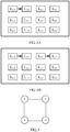
- FIG. 1 is a schematic diagram of an example of a routing network according to an embodiment of the present invention.
- a fully interconnected routing network that includes four routing nodes is used as an example.
- a channel dependency graph corresponding to FIG. 1 is shown in FIG. 2 .
- the channel dependency graph shown in FIG. 2 may also be understood as an original channel dependency graph.
- the channel dependency graph is defined as follows: Each channel shown in FIG. 1 is denoted by a node in the channel dependency graph, and a symbol L 1,2 in the channel dependency graph denotes a channel from a node 1 to a node 2. It is assumed that there is an arrow between L 1,2 and L 2,4 , and this indicates that the channel L 1,2 depends on the channel L 2,4 .
- the routing node 1 when a communication fault occurs between a routing node 1 and a routing node 4, the routing node 1 cannot directly communicate with the routing node 4.
- a routing node 3 may be used as a final intermediate routing node from the routing node 4 to the routing node 1, and a channel dependency relationship L 4,3 ->L 3,1 from L 4,3 to L 3,1 is added to FIG. 4A .
- FIG. 4B there is still no dependency relationship loop in a channel dependency graph. Therefore, the routing node 3 may be used as a final intermediate routing node from the routing node 4 to the routing node 1.
- a channel dependency relationship L 2,4 ->L 4,3 is added to FIG. 4B .
- an updated channel dependency graph is shown in FIG. 6 . Because there is no dependency relationship loop in the updated channel dependency graph shown in FIG. 6 , it may be determined that the routing node 4 may be used as a final intermediate routing node for communication from the routing node 2 to the routing node 3.
- a channel dependency relationship L 3,1 ->L 1,2 is added to the channel dependency graph in FIG. 6 .
- an updated channel dependency graph is shown in FIG. 7 . It may be found that there is a dependency relationship loop in the updated channel dependency graph in FIG. 7 . Therefore, the routing node 1 cannot be used as an intermediate routing node for communication from the routing node 3 to the routing node 2.
- a channel dependency graph that has a dependency relationship loop does not need to be saved, because no channel dependency graph that includes a dependency relationship loop will be used for next addition of a channel dependency relationship.
- the routing node 4 may be tried again and a channel dependency relationship L 3,4 ->L 4,2 is added to the channel dependency graph in FIG. 6 .
- an updated channel dependency graph is shown in FIG. 8 . Because there is no dependency relationship loop in the channel dependency graph shown in FIG. 8 , it is determined that the routing node 4 may be used as a final intermediate routing node for communication from the routing node 3 to the routing node 2.
- FIG. 9 is a schematic diagram of another embodiment of a routing network according to the embodiments of the present invention.
- six routing nodes are included.
- a routing node 1 in the routing network shown in FIG. 9 can separately perform direct communication with a routing node 5, a routing node 3, and a routing node 4.
- the routing node 1 needs to depend on the routing node 3 or the routing node 4 (in this case, it is assumed that an Up*/Down* routing algorithm is used), and the routing node 2 can perform direct communication with the routing node 3 and the routing node 4.
- FIG. 9 needs to enable any two routing nodes in FIG. 9 to perform communication, and to perform direct communication if direct communication can be performed, or to perform indirect communication by using another routing node if direct communication cannot be performed.
- other routing nodes that are used should be as few as possible. Therefore, the channel dependency graph corresponding to the routing network shown in FIG. 9 is shown in FIG. 10 .
- the routing node 2 is used as a to-be-verified intermediate routing node from the routing node 1 to the routing node 4, a last channel in a communication path between the routing node 1 and the routing node 2 is L 3,2 and the channel L 3,2 may be used as a dependency start channel, and a first channel in a communication path between the routing node 2 and the routing node 4 is L 2,4 and the channel L 2,4 may be used as a dependency end channel. Therefore, a channel dependency relationship L 3,2 -> L 2,4 from the channel L 3,2 to the channel L 2,4 is added to a channel dependency graph in which this fault has not occurred, that is, FIG. 10 . A new dependency relationship is added to the channel dependency graph shown in FIG. 10 to obtain an updated channel dependency graph. There is no dependency relationship loop in the updated channel dependency graph.
- the routing node 2 may be used as a final intermediate routing node between the routing node 1 and the routing node 4.
- a communication path between a source routing node, a to-be-verified intermediate routing node, and a destination routing node is constituted by connecting multiple channels in series.
- Channels from the source routing node to the to-be-verified intermediate routing node are respectively defined as a first channel, a second channel, ..., and a last channel starting from the source routing node, and channels from the to-be-verified intermediate routing node to the destination routing node are respectively defined as a first channel, a second channel, ..., and a last channel starting from the to-be-verified intermediate routing node.
- a process is the same as that described in the foregoing FIG. 1 to FIG. 8 .
- FIG. 9 and FIG. 10 it is only emphasized that a channel dependency graph is determined depending on a communication relationship, between routing nodes, predefined in a routing network. Not every two routing nodes can perform direct communication; however, two routing nodes can depend on another routing node to implement communication.
- an embodiment of a method for determining an intermediate routing node according to the embodiments of the present invention includes:
- the to-be-verified intermediate routing node is any one of the at least one intermediate routing node
- the channel dependency relationship is a combination of channels in which the two routing nodes perform data transmission by using the to-be-verified intermediate routing node
- the channel dependency graph of the routing network in which this fault has not occurred is used to describe a dependency relationship constituted by any two channels in the routing network in which this fault has not occurred, or a combination of a dependency relationship constituted by any two channels in the routing network in which this fault has not occurred and a channel dependency relationship that is established before the fault.
- a routing network has a fault-tolerance capability, recovery does not need to be performed once a fault occurs.
- a channel dependency relationship induced from a communication fault needs to be added to an initial channel dependency graph, and a channel dependency graph to which the channel dependency relationship is already added is an updated channel dependency graph.
- a channel dependency relationship induced from this fault needs to be added to a channel dependency graph that is obtained a channel dependency relationship is added at a previous time.
- the channel dependency graph is defined as follows: each node in a channel dependency graph denotes one channel in a routing network, and a symbol L1,2 in the channel dependency graph denotes one channel. If there is an arrow between L 1,2 and L 2,4 , as shown in FIG. 4A , this indicates that the channel L 1,2 and the channel L 2,4 depend on each other.
- the to-be-verified intermediate routing node determines the to-be-verified intermediate routing node as a final intermediate routing node that is used to transfer the to-be-transmitted data, where the dependency relationship loop is a loop constituted by a channel dependency relationship combination.
- At least one intermediate routing node that is used to transfer to-be-transmitted data between the two routing nodes is determined; a channel dependency relationship between a to-be-verified intermediate routing node and the two routing nodes is added to a channel dependency graph of a routing network in which this fault has not occurred, to enable the channel dependency graph to become an updated channel dependency graph, where the to-be-verified intermediate routing node is any one of the at least one intermediate routing node, the channel dependency relationship is a combination of channels in which the two routing nodes perform data transmission by using the to-be-verified intermediate routing node, and the channel dependency graph of the routing network in which this fault has not occurred is used to describe a channel constituted by any two routing nodes in the routing network in which this fault has not occurred, or a combination of a channel constituted by any two routing nodes in the routing network in which this fault has not occurred and a channel dependency relationship that is established before the fault; and
- an intermediate routing node that does not have a dependency relationship loop in a channel dependency graph may be determined by verifying, before determining the intermediate routing node, whether the intermediate routing node constitutes a dependency relationship loop in the channel dependency graph.
- to-be-transmitted data may be transferred by using only one intermediate routing node, without requiring that multiple virtual channels be in an idle and ready state. This improves resource utilization of a routing network. Therefore, in a network with same resources as a network in the prior art, a fault-tolerance capability is more powerful and network performance is better in this solution.
- the adding a channel dependency relationship between a to-be-verified intermediate routing node and the two routing nodes to a channel dependency graph of a routing network in which this fault has not occurred, to enable the channel dependency graph to become an updated channel dependency graph may include:
- a communication path between a source routing node, a to-be-verified intermediate routing node, and a destination routing node is constituted by connecting multiple channels in series.
- Channels from the source routing node to the to-be-verified intermediate routing node are respectively defined as a first channel, a second channel, ..., and a last channel starting from the source routing node, and channels from the to-be-verified intermediate routing node to the destination routing node are respectively defined as a first channel, a second channel, ..., and a last channel starting from the to-be-verified intermediate routing node.
- a process described in this embodiment of the present invention is a process of adding a line to a channel dependency graph, for example, a process of adding an arrow between the described L 1,2 and L 2,4 in FIG. 1 to FIG. 10 , and details are not described herein.
- the determining at least one intermediate routing node that is used to transfer to-be-transmitted data between the two routing nodes may include:
- a process described in this embodiment of the present invention is a process of step 2 to step 4 that are described in the foregoing FIG. 1 to FIG. 10 , and details are not described herein.
- the method may further include:
- the channel dependency graph of the routing network in which this fault has not occurred and that is described in this embodiment of the present invention is saved upon a previous update of a channel dependency graph and needs only to be directly read, which can improve efficiency in obtaining an updated channel dependency graph.
- the method may further include:
- a source routing node may directly send to-be-transmitted data according to the description information of the final intermediate routing node, and according to this embodiment of the present invention, a routing network needs only communication paths from the source routing node to the final intermediate routing node and from the final intermediate routing node to a destination routing nod, without requiring that another communication path be always in an idle and ready state. This improves resource utilization of the routing network.
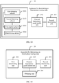
- an embodiment of an apparatus 20 for determining an intermediate routing node includes:
- a first determining unit 201 determines at least one intermediate routing node that is used to transfer to-be-transmitted data between the two routing nodes; a channel dependency graph update unit 202 adds a channel dependency relationship between a to-be-verified intermediate routing node and the two routing nodes to a channel dependency graph of a routing network in which this fault has not occurred, to enable the channel dependency graph to become an updated channel dependency graph, where the to-be-verified intermediate routing node is any one of the at least one intermediate routing node determined by the first determining unit, the channel dependency relationship is a combination of channels in which the two routing nodes perform data transmission by using the to-be-verified intermediate routing node, and the channel dependency graph of the routing network in which this fault has not occurred is used to describe a channel constituted by any two routing nodes in the routing network in which this fault has not occurred, or a combination of a channel constituted by any two routing nodes in
- an intermediate routing node that does not have a dependency relationship loop in a channel dependency graph may be determined by verifying, before determining the intermediate routing node, whether the intermediate routing node constitutes a dependency relationship loop in the channel dependency graph.
- to-be-transmitted data may be transferred by using only one intermediate routing node, without requiring that multiple virtual channels be in an idle and ready state.
- the channel dependency graph update unit 202 includes:
- the first determining unit 201 includes:
- the apparatus 20 further includes:
- the apparatus 20 further includes:
- FIG. 17 is a schematic structural diagram of an apparatus 20 for determining an intermediate routing node according to an embodiment of the present invention.
- the apparatus 20 for determining an intermediate routing node may include an input device 210, an output device 220, a processor 230, and a memory 240.
- the memory 240 may include a read-only memory and a random access memory, and provides an instruction and data to the processor 230.
- a part of the memory 240 may further include a non-volatile random access memory (NVRAM).
- NVRAM non-volatile random access memory
- the memory 240 stores the following elements: an executable module or a data structure, or a subset thereof, or an extended set thereof:
- the processor 230 performs the following operations by invoking an operation instruction (this operation instruction may be stored in an operating system) stored in the memory 240:
- an apparatus 20 for determining an intermediate routing node verifies whether the intermediate routing node constitutes a dependency relationship loop in a channel dependency graph, so that an intermediate routing node that does not have a dependency relationship loop in the channel dependency graph may be determined, and when a communication fault occurs between two routing nodes, to-be-transmitted data may be transferred by using only one intermediate routing node, without requiring that multiple virtual channels be in an idle and ready state.
- This improves resource utilization of a routing network. Therefore, in a network with same resources as a network in the prior art, a fault-tolerance capability is more powerful and network performance is better in this solution.
- the processor 230 controls an operation of the apparatus 20 for determining an intermediate routing node.
- the processor 230 may also be referred to as a CPU (Central Processing Unit, central processing unit).
- the memory 240 may include a read-only memory and a random access memory, and provides an instruction and data to the processor 230. A part of the memory 240 may further include a non-volatile random access memory (NVRAM).
- NVRAM non-volatile random access memory
- all components of the apparatus 20 for determining an intermediate routing node are coupled together by using a bus system 250, where the bus system 250 may further include a power bus, a control bus, a status signal bus, and the like in addition to a data bus.
- all types of buses are marked as the bus system 250 in FIG. 18 .
- the method disclosed in the embodiments of the present invention may be applied to the processor 230 or implemented by the processor 230.
- the processor 230 may be an integrated circuit chip with a signal processing capability. In an implementation process, steps of the foregoing method may be performed by an integrated logical circuit in hardware or by an instruction in a form of software in the processor 230.
- the foregoing processor 230 may be a general purpose processor, a digital signal processor (DSP), an application-specific integrated circuit (ASIC), a field programmable gate array (FPGA) or another programmable logic device, a discrete gate or a transistor logic device, or a discrete hardware assembly, and may implement or execute the methods, steps, and logical block diagrams that are disclosed in the embodiments of the present invention.
- DSP digital signal processor
- ASIC application-specific integrated circuit
- FPGA field programmable gate array
- the general purpose processor may be a microprocessor or the processor may be any conventional processor or the like. Steps of the method disclosed with reference to the embodiments of the present invention may be directly reflected as being executed by a decoding processor in a form of hardware, or may be executed by using a combination of hardware and software modules in a decoding processor.
- the software module may be located in a mature storage medium in the prior art, such as a random access memory, a flash memory, a read-only memory, a programmable read-only memory or an electrically-erasable programmable memory, or a register.
- the storage medium is located in the memory 240, and the processor 230 reads information from the memory 240 and performs, with reference to hardware thereof, the steps in the foregoing methods.
- the processor 230 may specifically:
- the processor 230 may specifically:
- processor 230 may further:
- the output device 220 may be configured to send description information of the intermediate routing node to the source routing node of the two routing nodes, so that the source routing node sends the to-be-transmitted data to the intermediate routing node.
- a routing control system includes: a routing node 30 and a management node 40, where any two routing nodes of the routing node 30 are in a communication connection in a manner defined according to a network topology, and there is a communication connection between the management node 40 and any routing node of the routing node 30.
- routing nodes 30 are drawn. In practice, there may be many routing nodes 30. It may be understood that not all are drawn in FIG. 18 .
- the management node 40 is configured to: when there is a fault in a communication path between two routing nodes, determine at least one intermediate routing node that is used to transfer to-be-transmitted data between the two routing nodes; add a channel dependency relationship between a to-be-verified intermediate routing node and the two routing nodes to a channel dependency graph of a routing network in which this fault has not occurred, to enable the channel dependency graph to become an updated channel dependency graph, where the to-be-verified intermediate routing node is any one of the at least one intermediate routing node, the channel dependency relationship is a combination of channels in which the two routing nodes perform data transmission by using the to-be-verified intermediate routing node, and the channel dependency graph of the routing network in which this fault has not occurred is used to describe a channel constituted by any two routing nodes in the routing network in which this fault has not occurred, or a combination of a channel constituted by any two routing nodes in the routing network in which this fault has not occurred and a channel dependency relationship that is established before the fault; and
- an intermediate routing node that does not have a dependency relationship loop in a channel dependency graph may be determined by verifying, before determining the intermediate routing node, whether the intermediate routing node constitutes a dependency relationship loop in the channel dependency graph.
- to-be-transmitted data may be transferred by using only one intermediate routing node, without requiring that multiple virtual channels be in an idle and ready state. This improves resource utilization of a routing network. Therefore, in a network with same resources as a network in the prior art, a fault-tolerance capability is more powerful and network performance is better in this solution.
- the program may be stored in a computer readable storage medium.
- the storage medium may include: a ROM, a RAM, a magnetic disk, or an optical disc.
Landscapes
- Engineering & Computer Science (AREA)
- Computer Networks & Wireless Communication (AREA)
- Signal Processing (AREA)
- Data Exchanges In Wide-Area Networks (AREA)
Claims (11)
- Procédé de détermination d'un noeud de routage intermédiaire, le procédé comprenant les étapes suivantes :en présence d'un défaut dans un trajet de communication entre deux noeuds de routage, détermination (101) d'au moins un noeud de routage intermédiaire utilisé pour le transfert de données à transmettre entre les deux noeuds de routage ;ajout (102) d'une relation de dépendance de canaux entre un noeud de routage intermédiaire à vérifier et les deux noeuds de routage à un graphe de dépendance de canaux d'un réseau de routage dans lequel ce défaut ne s'est pas produit pour que le graphe de dépendance de canaux devienne un graphe de dépendance de canaux actualisé, le noeud de routage intermédiaire à vérifier représentant l'un quelconque de l'au moins un noeud de routage intermédiaire, la relation de dépendance de canaux représentant une combinaison de canaux où les deux noeuds de routage effectuent une transmission de données au moyen du noeud de routage intermédiaire à vérifier, et le graphe de dépendance de canaux du réseau de routage dans lequel ce défaut ne s'est pas produit étant utilisé pour décrire une relation de dépendance constituée de deux canaux quelconques dans le réseau de routage dans lequel ce défaut ne s'est pas produit, ou une combinaison d'une relation de dépendance constituée de deux canaux quelconques dans le réseau de routage dans lequel ce défaut ne s'est pas produit et d'une relation de dépendance de canaux établie avant le défaut ; etsi le graphe de dépendance de canaux actualisé ne dispose pas d'une boucle de relations de dépendance, détermination (103) du noeud de routage intermédiaire à vérifier comme noeud de routage intermédiaire final utilisé pour le transfert des données à transmettre, la boucle de relations de dépendance représentant une boucle constituée d'une combinaison de relations de dépendance de canaux.
- Procédé selon la revendication 1, dans lequel l'étape d'ajout d'une relation de dépendance de canaux entre un noeud de routage intermédiaire à vérifier et les deux noeuds de routage à un graphe de dépendance de canaux d'un réseau de routage dans lequel ce défaut ne s'est pas produit pour que le graphe de dépendance de canaux devienne un graphe de dépendance de canaux actualisé comprend les étapes suivantes :exploration, selon un sens de transmission des données à transmettre, du graphe de dépendance de canaux du réseau de routage dans lequel ce défaut ne s'est pas produit afin d'identifier un dernier canal dans un trajet entre un noeud de routage source parmi les deux noeuds de routage et le noeud de routage intermédiaire à vérifier et un premier canal dans un trajet entre le noeud de routage intermédiaire à vérifier et un noeud de routage destinataire parmi les deux noeuds de routage ;détermination du dernier canal dans le trajet entre le noeud de routage source et le noeud de routage intermédiaire à vérifier au titre d'un canal de début de dépendance, et détermination du premier canal dans le trajet entre le noeud de routage intermédiaire à vérifier et le noeud de routage destinataire au titre d'un canal de fin de dépendance ; etajout au graphe de dépendance de canaux du réseau de routage dans lequel ce défaut ne s'est pas produit d'une relation de dépendance de canaux depuis le canal de début de dépendance jusqu'au canal de fin de dépendance de façon à ce que le graphe de dépendance de canaux du réseau de routage dans lequel ce défaut ne s'est pas produit devienne le graphe de dépendance de canaux actualisé.
- Procédé selon la revendication 1 ou 2, dans lequel l'étape de détermination d'au moins un noeud de routage intermédiaire utilisé pour le transfert de données à transmettre entre les deux noeuds de routage comprend les étapes suivantes :obtention, à titre de premier ensemble d'informations, d'informations concernant un noeud de routage dans une connexion de communication sans défaut au noeud de routage source parmi les deux noeuds de routage ;obtention, à titre de deuxième ensemble d'informations, d'informations concernant un noeud de routage dans une connexion de communication sans défaut au noeud de routage destinataire parmi les deux noeuds de routage, et calcul d'un ensemble d'intersection du premier ensemble d'informations et du deuxième ensemble d'informations ; etdétermination, à titre de l'au moins un noeud de routage intermédiaire, d'un noeud de routage correspondant à des informations de noeud de routage contenues dans l'ensemble d'intersection.
- Procédé selon la revendication 1 ou 2, le procédé comprenant en outre, avant l'étape d'ajout d'une relation de dépendance de canaux entre un noeud de routage intermédiaire à vérifier et les deux noeuds de routage à un graphe de dépendance de canaux d'un réseau de routage dans lequel ce défaut ne s'est pas produit pour que le graphe de dépendance de canaux devienne un graphe de dépendance de canaux actualisé, l'étape suivante :obtention, à titre du graphe de dépendance de canaux du réseau de routage dans lequel ce défaut ne s'est pas produit, d'un graphe de dépendance de canaux qui ne contient pas une boucle de relations de dépendance et qui est obtenu une relation de dépendance de canaux est ajoutée antérieurement.
- Procédé selon la revendication 1 ou 2, le procédé comprenant en outre l'étape suivante :envoi d'informations de description relatives au noeud de routage intermédiaire final au noeud de routage source parmi les deux noeuds de routage, de façon à ce que le noeud de routage source envoie les données à transmettre au noeud de routage intermédiaire final.
- Appareil (20) permettant de déterminer un noeud de routage intermédiaire, l'appareil comprenant :une première unité de détermination (201), configurée pour : en présence d'un défaut dans un trajet de communication entre deux noeuds de routage, déterminer au moins un noeud de routage intermédiaire utilisé pour le transfert de données à transmettre entre les deux noeuds de routage ;une unité d'actualisation de graphe de dépendance de canaux (202), configurée pour ajouter une relation de dépendance de canaux entre un noeud de routage intermédiaire à vérifier et les deux noeuds de routage à un graphe de dépendance de canaux d'un réseau de routage dans lequel ce défaut ne s'est pas produit pour que le graphe de dépendance de canaux devienne un graphe de dépendance de canaux actualisé, le noeud de routage intermédiaire à vérifier représentant l'un quelconque de l'au moins un noeud de routage intermédiaire déterminé par la première unité de détermination, la relation de dépendance de canaux représentant une combinaison de canaux où les deux noeuds de routage effectuent une transmission de données au moyen du noeud de routage intermédiaire à vérifier, et le graphe de dépendance de canaux du réseau de routage dans lequel ce défaut ne s'est pas produit étant utilisé pour décrire une relation de dépendance constituée de deux canaux quelconques dans le réseau de routage dans lequel ce défaut ne s'est pas produit, ou une combinaison d'une relation de dépendance constituée de deux canaux quelconques dans le réseau de routage dans lequel ce défaut ne s'est pas produit et d'une relation de dépendance de canaux établie avant le défaut ; etune deuxième unité de détermination (203), configurée pour : si le graphe de dépendance de canaux actualisé par l'unité d'actualisation de graphe de dépendance de canaux ne dispose pas d'une boucle de relations de dépendance, déterminer le noeud de routage intermédiaire à vérifier comme noeud de routage intermédiaire final utilisé pour le transfert des données à transmettre, la boucle de relations de dépendance représentant une boucle constituée d'une combinaison de relations de dépendance de canaux.
- Appareil selon la revendication 6, dans lequel l'unité d'actualisation de graphe de dépendance de canaux comprend :une sous-unité d'exploration, configurée pour explorer, selon un sens de transmission des données à transmettre, le graphe de dépendance de canaux du réseau de routage dans lequel ce défaut ne s'est pas produit afin d'identifier un dernier canal dans un trajet entre un noeud de routage source parmi les deux noeuds de routage et le noeud de routage intermédiaire à vérifier et un premier canal dans un trajet entre le noeud de routage intermédiaire à vérifier et un noeud de routage destinataire parmi les deux noeuds de routage ;une sous-unité de détermination, configurée pour déterminer le dernier canal, identifié par la sous-unité d'exploration, dans le trajet entre le noeud de routage source et le noeud de routage intermédiaire à vérifier comme canal de début de dépendance, et déterminer le premier canal, identifié par la sous-unité d'exploration, dans le trajet entre le noeud de routage intermédiaire à vérifier et le noeud de routage destinataire au titre d'un canal de fin de dépendance ; etune sous-unité d'établissement, configurée pour ajouter au graphe de dépendance de canaux du réseau de routage dans lequel ce défaut ne s'est pas produit une relation de dépendance de canaux depuis le canal de début de dépendance jusqu'au canal de fin de dépendance, le canal de début de dépendance et le canal de fin de dépendance étant déterminés par la sous-unité de détermination, de façon à ce que le graphe de dépendance de canaux du réseau de routage dans lequel ce défaut ne s'est pas produit devienne le graphe de dépendance de canaux actualisé.
- Appareil selon la revendication 6 ou 7, dans lequel la première unité de détermination comprend :une première sous-unité d'obtention, configurée pour obtenir, à titre de premier ensemble d'informations, des informations concernant un noeud de routage dans une connexion de communication sans défaut au noeud de routage source parmi les deux noeuds de routage ;une deuxième sous-unité d'obtention, configurée pour obtenir, à titre de deuxième ensemble d'informations, des informations concernant un noeud de routage dans une connexion de communication sans défaut au noeud de routage destinataire parmi les deux noeuds de routage ;une sous-unité de calcul, configurée pour calculer un ensemble d'intersection du premier ensemble d'informations obtenu par la première sous-unité d'obtention et du deuxième ensemble d'informations obtenu par la deuxième sous-unité d'obtention ; etune sous-unité de détermination, configurée pour déterminer, comme l'au moins un noeud de routage intermédiaire, un noeud de routage correspondant à des informations de noeud de routage contenues dans l'ensemble d'intersection calculé par la sous-unité de calcul.
- Appareil selon la revendication 6 ou 7, l'appareil comprenant en outre :une unité d'obtention, configurée pour : avant que l'unité d'actualisation de graphe de dépendance de canaux n'actualise le graphe de dépendance de canaux du réseau de routage dans lequel ce défaut ne s'est pas produit, obtenir, à titre du graphe de dépendance de canaux du réseau de routage dans lequel ce défaut ne s'est pas produit, un graphe de dépendance de canaux qui ne contient pas une boucle de relations de dépendance et qui est obtenu une relation de dépendance de canaux est ajoutée antérieurement.
- Appareil selon la revendication 6 ou 7, l'appareil comprenant en outre :une unité d'envoi, configurée pour envoyer des informations de description relatives au noeud de routage intermédiaire final déterminé par la deuxième unité de détermination au noeud de routage source parmi les deux noeuds de routage, de façon à ce que le noeud de routage source envoie les données à transmettre au noeud de routage intermédiaire final.
- Système de commande de routage, comprenant : un noeud de routage (30) et un noeud de gestion (40), le noeud de routage se trouvant dans une connexion de communication d'une manière définie selon une topologie de réseau, et une connexion de communication existant entre le noeud de gestion et un noeud de routage quelconque des noeuds de routage ; et
le noeud de gestion étant configuré pour : en présence d'un défaut dans un trajet de communication entre deux noeuds de routage, déterminer au moins un noeud de routage intermédiaire utilisé pour le transfert de données à transmettre entre les deux noeuds de routage ; ajouter une relation de dépendance de canaux entre un noeud de routage intermédiaire à vérifier et les deux noeuds de routage à un graphe de dépendance de canaux d'un réseau de routage dans lequel ce défaut ne s'est pas produit pour que le graphe de dépendance de canaux devienne un graphe de dépendance de canaux actualisé, le noeud de routage intermédiaire à vérifier représentant l'un quelconque de l'au moins un noeud de routage intermédiaire, la relation de dépendance de canaux représentant une combinaison de canaux où les deux noeuds de routage effectuent une transmission de données au moyen du noeud de routage intermédiaire à vérifier, et le graphe de dépendance de canaux du réseau de routage dans lequel ce défaut ne s'est pas produit étant utilisé pour décrire un canal constitué de deux noeuds de routage quelconques dans le réseau de routage dans lequel ce défaut ne s'est pas produit, ou une combinaison d'un canal constitué de deux noeuds de routage quelconques dans le réseau de routage dans lequel ce défaut ne s'est pas produit et d'une relation de dépendance de canaux établie avant le défaut ; et si le graphe de dépendance de canaux actualisé ne dispose pas d'une boucle de relations de dépendance, déterminer le noeud de routage intermédiaire à vérifier comme noeud de routage intermédiaire final utilisé pour le transfert des données à transmettre, la boucle de relations de dépendance représentant une boucle constituée d'une combinaison de relations de dépendance de canaux.
Applications Claiming Priority (2)
| Application Number | Priority Date | Filing Date | Title |
|---|---|---|---|
| CN201410182254.XA CN105099904B (zh) | 2014-04-30 | 2014-04-30 | 一种确定中间路由节点的方法、装置及系统 |
| PCT/CN2015/070038 WO2015165280A1 (fr) | 2014-04-30 | 2015-01-04 | Procédé, dispositif et système pour déterminer un nœud de routage intermédiaire |
Publications (3)
| Publication Number | Publication Date |
|---|---|
| EP3125478A1 EP3125478A1 (fr) | 2017-02-01 |
| EP3125478A4 EP3125478A4 (fr) | 2017-04-26 |
| EP3125478B1 true EP3125478B1 (fr) | 2018-03-07 |
Family
ID=54358138
Family Applications (1)
| Application Number | Title | Priority Date | Filing Date |
|---|---|---|---|
| EP15785832.5A Active EP3125478B1 (fr) | 2014-04-30 | 2015-01-04 | Procédé, dispositif et système pour déterminer un noeud de routage intermédiaire |
Country Status (4)
| Country | Link |
|---|---|
| US (1) | US9906435B2 (fr) |
| EP (1) | EP3125478B1 (fr) |
| CN (1) | CN105099904B (fr) |
| WO (1) | WO2015165280A1 (fr) |
Families Citing this family (6)
| Publication number | Priority date | Publication date | Assignee | Title |
|---|---|---|---|---|
| US10474445B2 (en) * | 2015-12-07 | 2019-11-12 | Microsoft Technology Licensing, Llc | Updating dependent services |
| CN111294226B (zh) * | 2018-12-10 | 2023-05-09 | 华为技术有限公司 | 通信方法和装置 |
| CN113076129B (zh) * | 2021-03-23 | 2023-11-28 | 成都安恒信息技术有限公司 | 一种复杂配置依赖关系自动检查处理方法 |
| US12327077B2 (en) * | 2022-05-04 | 2025-06-10 | Xilinx, Inc. | Deadlock detection and prevention for routing packet-switched nets in electronic systems |
| US12468584B2 (en) * | 2022-10-21 | 2025-11-11 | Bank Of America Corporation | Determining and managing interactions between application sub-systems using machine learning |
| US20250181384A1 (en) * | 2023-11-30 | 2025-06-05 | Advanced Micro Devices, Inc. | Task Graph Control of Data Transfer |
Family Cites Families (10)
| Publication number | Priority date | Publication date | Assignee | Title |
|---|---|---|---|---|
| US4933933A (en) * | 1986-12-19 | 1990-06-12 | The California Institute Of Technology | Torus routing chip |
| CN100414878C (zh) * | 2002-09-23 | 2008-08-27 | 华为技术有限公司 | 基于异步传输模式的网络互连管理实现方法 |
| GB2421158B (en) * | 2003-10-03 | 2007-07-11 | Avici Systems Inc | Rapid alternate paths for network destinations |
| US9088502B2 (en) | 2011-05-23 | 2015-07-21 | Cisco Technology, Inc. | Generating a loop-free routing topology using routing arcs |
| CN103179034B (zh) * | 2011-12-22 | 2016-01-20 | 清华大学 | 无死锁自适应路由方法 |
| CN102546425B (zh) * | 2012-01-31 | 2014-11-05 | 华为技术有限公司 | 相交环保护方法、设备和系统 |
| CN102761475B (zh) * | 2012-03-27 | 2015-08-05 | 西安交通大学 | 一种基于通道依赖关系图的片上互联网络容错路由方法 |
| US9178798B2 (en) * | 2012-05-09 | 2015-11-03 | Juniper Networks, Inc. | Fast reroute using loop free alternate next hops for multipoint label switched paths |
| US9244880B2 (en) * | 2012-08-30 | 2016-01-26 | Netspeed Systems | Automatic construction of deadlock free interconnects |
| US9485136B2 (en) * | 2013-12-09 | 2016-11-01 | Cisco Technology, Inc. | Repair of failed network routing arcs using data plane protocol |
-
2014
- 2014-04-30 CN CN201410182254.XA patent/CN105099904B/zh active Active
-
2015
- 2015-01-04 EP EP15785832.5A patent/EP3125478B1/fr active Active
- 2015-01-04 WO PCT/CN2015/070038 patent/WO2015165280A1/fr not_active Ceased
-
2016
- 2016-10-25 US US15/333,500 patent/US9906435B2/en active Active
Non-Patent Citations (1)
| Title |
|---|
| None * |
Also Published As
| Publication number | Publication date |
|---|---|
| US20170041216A1 (en) | 2017-02-09 |
| EP3125478A1 (fr) | 2017-02-01 |
| WO2015165280A1 (fr) | 2015-11-05 |
| US9906435B2 (en) | 2018-02-27 |
| EP3125478A4 (fr) | 2017-04-26 |
| CN105099904B (zh) | 2018-06-05 |
| CN105099904A (zh) | 2015-11-25 |
Similar Documents
| Publication | Publication Date | Title |
|---|---|---|
| US9906435B2 (en) | Method and apparatus for determining intermediate routing node and system | |
| US10164782B2 (en) | Method and system for constructing a loop free multicast tree in a data-center fabric | |
| CN110166356B (zh) | 发送报文的方法和网络设备 | |
| US8537720B2 (en) | Aggregating data traffic from access domains | |
| US10848416B2 (en) | Reduced configuration for multi-stage network fabrics | |
| EP2774329B1 (fr) | Architectures de réseaux de centres de données | |
| US11799753B2 (en) | Dynamic discovery of service nodes in a network | |
| CN111682927A (zh) | 一种基于mlag环境的报文同步方法、装置、设备及介质 | |
| US10498643B2 (en) | Method for constructing multipath forwarding rule, apparatus, and system | |
| US11431619B2 (en) | Hierarchical ECMP control plane for dense topologies | |
| CN109861925A (zh) | 数据传输方法、相关装置及网络 | |
| EP3213441B1 (fr) | Redondance pour chaînes d'extension de port | |
| WO2019000953A1 (fr) | Procédé, dispositif et système permettant de mettre en œuvre une machine mux | |
| CN114531396B (zh) | 一种以太网虚拟专用网络中的故障回切方法及装置 | |
| US8842543B2 (en) | Trap-free shortest link-disjoint paths | |
| US10979328B2 (en) | Resource monitoring | |
| CN102932250A (zh) | 一种基于容错计算机网络结构的无死锁自适应路由方法 | |
| CN107181689B (zh) | 路由器之间的消息交互方法和装置 | |
| WO2019000952A1 (fr) | Procédé, dispositif et système permettant de mettre en œuvre une machine mux | |
| CN116319536B (zh) | 基于sdwan主备链路的数据传输方法、装置、电子设备和存储介质 | |
| US8842544B2 (en) | Trap-free shortest link-and-shared risk link group-disjoint paths | |
| CN108390780B (zh) | 用于处理信息的方法和装置 | |
| JP6665607B2 (ja) | 通信管理方法、通信管理プログラム及び情報処理装置 | |
| CN103763170A (zh) | 环网保护方法及装置 | |
| CN111385182B (zh) | 流量的传输方法及装置,系统 |
Legal Events
| Date | Code | Title | Description |
|---|---|---|---|
| STAA | Information on the status of an ep patent application or granted ep patent |
Free format text: STATUS: THE INTERNATIONAL PUBLICATION HAS BEEN MADE |
|
| PUAI | Public reference made under article 153(3) epc to a published international application that has entered the european phase |
Free format text: ORIGINAL CODE: 0009012 |
|
| STAA | Information on the status of an ep patent application or granted ep patent |
Free format text: STATUS: REQUEST FOR EXAMINATION WAS MADE |
|
| 17P | Request for examination filed |
Effective date: 20161028 |
|
| AK | Designated contracting states |
Kind code of ref document: A1 Designated state(s): AL AT BE BG CH CY CZ DE DK EE ES FI FR GB GR HR HU IE IS IT LI LT LU LV MC MK MT NL NO PL PT RO RS SE SI SK SM TR |
|
| AX | Request for extension of the european patent |
Extension state: BA ME |
|
| A4 | Supplementary search report drawn up and despatched |
Effective date: 20170324 |
|
| RIC1 | Information provided on ipc code assigned before grant |
Ipc: H04L 12/751 20130101ALI20170320BHEP Ipc: H04L 12/705 20130101ALI20170320BHEP Ipc: H04L 12/703 20130101AFI20170320BHEP Ipc: H04L 12/707 20130101ALI20170320BHEP |
|
| DAX | Request for extension of the european patent (deleted) | ||
| GRAP | Despatch of communication of intention to grant a patent |
Free format text: ORIGINAL CODE: EPIDOSNIGR1 |
|
| STAA | Information on the status of an ep patent application or granted ep patent |
Free format text: STATUS: GRANT OF PATENT IS INTENDED |
|
| RIC1 | Information provided on ipc code assigned before grant |
Ipc: H04L 12/707 20130101ALI20170822BHEP Ipc: H04L 12/703 20130101AFI20170822BHEP Ipc: H04L 12/705 20130101ALI20170822BHEP Ipc: H04L 12/751 20130101ALI20170822BHEP |
|
| INTG | Intention to grant announced |
Effective date: 20170907 |
|
| GRAS | Grant fee paid |
Free format text: ORIGINAL CODE: EPIDOSNIGR3 |
|
| GRAA | (expected) grant |
Free format text: ORIGINAL CODE: 0009210 |
|
| STAA | Information on the status of an ep patent application or granted ep patent |
Free format text: STATUS: THE PATENT HAS BEEN GRANTED |
|
| RIN1 | Information on inventor provided before grant (corrected) |
Inventor name: FU, BINZHANG |
|
| AK | Designated contracting states |
Kind code of ref document: B1 Designated state(s): AL AT BE BG CH CY CZ DE DK EE ES FI FR GB GR HR HU IE IS IT LI LT LU LV MC MK MT NL NO PL PT RO RS SE SI SK SM TR |
|
| REG | Reference to a national code |
Ref country code: GB Ref legal event code: FG4D |
|
| REG | Reference to a national code |
Ref country code: CH Ref legal event code: EP Ref country code: AT Ref legal event code: REF Ref document number: 977690 Country of ref document: AT Kind code of ref document: T Effective date: 20180315 |
|
| REG | Reference to a national code |
Ref country code: IE Ref legal event code: FG4D |
|
| REG | Reference to a national code |
Ref country code: DE Ref legal event code: R096 Ref document number: 602015008611 Country of ref document: DE |
|
| REG | Reference to a national code |
Ref country code: NL Ref legal event code: MP Effective date: 20180307 |
|
| REG | Reference to a national code |
Ref country code: LT Ref legal event code: MG4D |
|
| PG25 | Lapsed in a contracting state [announced via postgrant information from national office to epo] |
Ref country code: NO Free format text: LAPSE BECAUSE OF FAILURE TO SUBMIT A TRANSLATION OF THE DESCRIPTION OR TO PAY THE FEE WITHIN THE PRESCRIBED TIME-LIMIT Effective date: 20180607 Ref country code: FI Free format text: LAPSE BECAUSE OF FAILURE TO SUBMIT A TRANSLATION OF THE DESCRIPTION OR TO PAY THE FEE WITHIN THE PRESCRIBED TIME-LIMIT Effective date: 20180307 Ref country code: HR Free format text: LAPSE BECAUSE OF FAILURE TO SUBMIT A TRANSLATION OF THE DESCRIPTION OR TO PAY THE FEE WITHIN THE PRESCRIBED TIME-LIMIT Effective date: 20180307 Ref country code: LT Free format text: LAPSE BECAUSE OF FAILURE TO SUBMIT A TRANSLATION OF THE DESCRIPTION OR TO PAY THE FEE WITHIN THE PRESCRIBED TIME-LIMIT Effective date: 20180307 Ref country code: CY Free format text: LAPSE BECAUSE OF FAILURE TO SUBMIT A TRANSLATION OF THE DESCRIPTION OR TO PAY THE FEE WITHIN THE PRESCRIBED TIME-LIMIT Effective date: 20180307 Ref country code: ES Free format text: LAPSE BECAUSE OF FAILURE TO SUBMIT A TRANSLATION OF THE DESCRIPTION OR TO PAY THE FEE WITHIN THE PRESCRIBED TIME-LIMIT Effective date: 20180307 |
|
| REG | Reference to a national code |
Ref country code: AT Ref legal event code: MK05 Ref document number: 977690 Country of ref document: AT Kind code of ref document: T Effective date: 20180307 |
|
| PG25 | Lapsed in a contracting state [announced via postgrant information from national office to epo] |
Ref country code: RS Free format text: LAPSE BECAUSE OF FAILURE TO SUBMIT A TRANSLATION OF THE DESCRIPTION OR TO PAY THE FEE WITHIN THE PRESCRIBED TIME-LIMIT Effective date: 20180307 Ref country code: GR Free format text: LAPSE BECAUSE OF FAILURE TO SUBMIT A TRANSLATION OF THE DESCRIPTION OR TO PAY THE FEE WITHIN THE PRESCRIBED TIME-LIMIT Effective date: 20180608 Ref country code: LV Free format text: LAPSE BECAUSE OF FAILURE TO SUBMIT A TRANSLATION OF THE DESCRIPTION OR TO PAY THE FEE WITHIN THE PRESCRIBED TIME-LIMIT Effective date: 20180307 Ref country code: SE Free format text: LAPSE BECAUSE OF FAILURE TO SUBMIT A TRANSLATION OF THE DESCRIPTION OR TO PAY THE FEE WITHIN THE PRESCRIBED TIME-LIMIT Effective date: 20180307 Ref country code: BG Free format text: LAPSE BECAUSE OF FAILURE TO SUBMIT A TRANSLATION OF THE DESCRIPTION OR TO PAY THE FEE WITHIN THE PRESCRIBED TIME-LIMIT Effective date: 20180607 |
|
| PG25 | Lapsed in a contracting state [announced via postgrant information from national office to epo] |
Ref country code: AL Free format text: LAPSE BECAUSE OF FAILURE TO SUBMIT A TRANSLATION OF THE DESCRIPTION OR TO PAY THE FEE WITHIN THE PRESCRIBED TIME-LIMIT Effective date: 20180307 Ref country code: NL Free format text: LAPSE BECAUSE OF FAILURE TO SUBMIT A TRANSLATION OF THE DESCRIPTION OR TO PAY THE FEE WITHIN THE PRESCRIBED TIME-LIMIT Effective date: 20180307 Ref country code: PL Free format text: LAPSE BECAUSE OF FAILURE TO SUBMIT A TRANSLATION OF THE DESCRIPTION OR TO PAY THE FEE WITHIN THE PRESCRIBED TIME-LIMIT Effective date: 20180307 Ref country code: RO Free format text: LAPSE BECAUSE OF FAILURE TO SUBMIT A TRANSLATION OF THE DESCRIPTION OR TO PAY THE FEE WITHIN THE PRESCRIBED TIME-LIMIT Effective date: 20180307 Ref country code: EE Free format text: LAPSE BECAUSE OF FAILURE TO SUBMIT A TRANSLATION OF THE DESCRIPTION OR TO PAY THE FEE WITHIN THE PRESCRIBED TIME-LIMIT Effective date: 20180307 |
|
| PG25 | Lapsed in a contracting state [announced via postgrant information from national office to epo] |
Ref country code: CZ Free format text: LAPSE BECAUSE OF FAILURE TO SUBMIT A TRANSLATION OF THE DESCRIPTION OR TO PAY THE FEE WITHIN THE PRESCRIBED TIME-LIMIT Effective date: 20180307 Ref country code: SM Free format text: LAPSE BECAUSE OF FAILURE TO SUBMIT A TRANSLATION OF THE DESCRIPTION OR TO PAY THE FEE WITHIN THE PRESCRIBED TIME-LIMIT Effective date: 20180307 Ref country code: AT Free format text: LAPSE BECAUSE OF FAILURE TO SUBMIT A TRANSLATION OF THE DESCRIPTION OR TO PAY THE FEE WITHIN THE PRESCRIBED TIME-LIMIT Effective date: 20180307 Ref country code: SK Free format text: LAPSE BECAUSE OF FAILURE TO SUBMIT A TRANSLATION OF THE DESCRIPTION OR TO PAY THE FEE WITHIN THE PRESCRIBED TIME-LIMIT Effective date: 20180307 |
|
| REG | Reference to a national code |
Ref country code: DE Ref legal event code: R097 Ref document number: 602015008611 Country of ref document: DE |
|
| PG25 | Lapsed in a contracting state [announced via postgrant information from national office to epo] |
Ref country code: PT Free format text: LAPSE BECAUSE OF FAILURE TO SUBMIT A TRANSLATION OF THE DESCRIPTION OR TO PAY THE FEE WITHIN THE PRESCRIBED TIME-LIMIT Effective date: 20180709 |
|
| PLBE | No opposition filed within time limit |
Free format text: ORIGINAL CODE: 0009261 |
|
| STAA | Information on the status of an ep patent application or granted ep patent |
Free format text: STATUS: NO OPPOSITION FILED WITHIN TIME LIMIT |
|
| PG25 | Lapsed in a contracting state [announced via postgrant information from national office to epo] |
Ref country code: DK Free format text: LAPSE BECAUSE OF FAILURE TO SUBMIT A TRANSLATION OF THE DESCRIPTION OR TO PAY THE FEE WITHIN THE PRESCRIBED TIME-LIMIT Effective date: 20180307 |
|
| 26N | No opposition filed |
Effective date: 20181210 |
|
| PG25 | Lapsed in a contracting state [announced via postgrant information from national office to epo] |
Ref country code: SI Free format text: LAPSE BECAUSE OF FAILURE TO SUBMIT A TRANSLATION OF THE DESCRIPTION OR TO PAY THE FEE WITHIN THE PRESCRIBED TIME-LIMIT Effective date: 20180307 Ref country code: IT Free format text: LAPSE BECAUSE OF FAILURE TO SUBMIT A TRANSLATION OF THE DESCRIPTION OR TO PAY THE FEE WITHIN THE PRESCRIBED TIME-LIMIT Effective date: 20180307 |
|
| PG25 | Lapsed in a contracting state [announced via postgrant information from national office to epo] |
Ref country code: MC Free format text: LAPSE BECAUSE OF FAILURE TO SUBMIT A TRANSLATION OF THE DESCRIPTION OR TO PAY THE FEE WITHIN THE PRESCRIBED TIME-LIMIT Effective date: 20180307 |
|
| REG | Reference to a national code |
Ref country code: CH Ref legal event code: PL |
|
| PG25 | Lapsed in a contracting state [announced via postgrant information from national office to epo] |
Ref country code: LU Free format text: LAPSE BECAUSE OF NON-PAYMENT OF DUE FEES Effective date: 20190104 |
|
| REG | Reference to a national code |
Ref country code: BE Ref legal event code: MM Effective date: 20190131 |
|
| REG | Reference to a national code |
Ref country code: IE Ref legal event code: MM4A |
|
| PG25 | Lapsed in a contracting state [announced via postgrant information from national office to epo] |
Ref country code: BE Free format text: LAPSE BECAUSE OF NON-PAYMENT OF DUE FEES Effective date: 20190131 |
|
| PG25 | Lapsed in a contracting state [announced via postgrant information from national office to epo] |
Ref country code: CH Free format text: LAPSE BECAUSE OF NON-PAYMENT OF DUE FEES Effective date: 20190131 Ref country code: LI Free format text: LAPSE BECAUSE OF NON-PAYMENT OF DUE FEES Effective date: 20190131 |
|
| PG25 | Lapsed in a contracting state [announced via postgrant information from national office to epo] |
Ref country code: IE Free format text: LAPSE BECAUSE OF NON-PAYMENT OF DUE FEES Effective date: 20190104 |
|
| PG25 | Lapsed in a contracting state [announced via postgrant information from national office to epo] |
Ref country code: TR Free format text: LAPSE BECAUSE OF FAILURE TO SUBMIT A TRANSLATION OF THE DESCRIPTION OR TO PAY THE FEE WITHIN THE PRESCRIBED TIME-LIMIT Effective date: 20180307 |
|
| PG25 | Lapsed in a contracting state [announced via postgrant information from national office to epo] |
Ref country code: MT Free format text: LAPSE BECAUSE OF NON-PAYMENT OF DUE FEES Effective date: 20190104 |
|
| PG25 | Lapsed in a contracting state [announced via postgrant information from national office to epo] |
Ref country code: IS Free format text: LAPSE BECAUSE OF FAILURE TO SUBMIT A TRANSLATION OF THE DESCRIPTION OR TO PAY THE FEE WITHIN THE PRESCRIBED TIME-LIMIT Effective date: 20180707 |
|
| PG25 | Lapsed in a contracting state [announced via postgrant information from national office to epo] |
Ref country code: HU Free format text: LAPSE BECAUSE OF FAILURE TO SUBMIT A TRANSLATION OF THE DESCRIPTION OR TO PAY THE FEE WITHIN THE PRESCRIBED TIME-LIMIT; INVALID AB INITIO Effective date: 20150104 |
|
| REG | Reference to a national code |
Ref country code: DE Ref legal event code: R079 Ref document number: 602015008611 Country of ref document: DE Free format text: PREVIOUS MAIN CLASS: H04L0012703000 Ipc: H04L0045280000 |
|
| PG25 | Lapsed in a contracting state [announced via postgrant information from national office to epo] |
Ref country code: MK Free format text: LAPSE BECAUSE OF FAILURE TO SUBMIT A TRANSLATION OF THE DESCRIPTION OR TO PAY THE FEE WITHIN THE PRESCRIBED TIME-LIMIT Effective date: 20180307 |
|
| REG | Reference to a national code |
Ref country code: FR Ref legal event code: PLFP Year of fee payment: 9 |
|
| PGFP | Annual fee paid to national office [announced via postgrant information from national office to epo] |
Ref country code: GB Payment date: 20251204 Year of fee payment: 12 |
|
| PGFP | Annual fee paid to national office [announced via postgrant information from national office to epo] |
Ref country code: FR Payment date: 20251208 Year of fee payment: 12 |
|
| PGFP | Annual fee paid to national office [announced via postgrant information from national office to epo] |
Ref country code: DE Payment date: 20251203 Year of fee payment: 12 |