EP3125980B1 - Zähler für inhalator mit abgemessener dosis mit schalter und inhalator mit abgemessener dosis mit solch einem zähler - Google Patents
Zähler für inhalator mit abgemessener dosis mit schalter und inhalator mit abgemessener dosis mit solch einem zähler Download PDFInfo
- Publication number
- EP3125980B1 EP3125980B1 EP15760292.1A EP15760292A EP3125980B1 EP 3125980 B1 EP3125980 B1 EP 3125980B1 EP 15760292 A EP15760292 A EP 15760292A EP 3125980 B1 EP3125980 B1 EP 3125980B1
- Authority
- EP
- European Patent Office
- Prior art keywords
- canister
- metered
- actuation housing
- triggering unit
- dose inhaler
- Prior art date
- Legal status (The legal status is an assumption and is not a legal conclusion. Google has not performed a legal analysis and makes no representation as to the accuracy of the status listed.)
- Active
Links
Images




Classifications
-
- A—HUMAN NECESSITIES
- A61—MEDICAL OR VETERINARY SCIENCE; HYGIENE
- A61M—DEVICES FOR INTRODUCING MEDIA INTO, OR ONTO, THE BODY; DEVICES FOR TRANSDUCING BODY MEDIA OR FOR TAKING MEDIA FROM THE BODY; DEVICES FOR PRODUCING OR ENDING SLEEP OR STUPOR
- A61M15/00—Inhalators
- A61M15/0065—Inhalators with dosage or measuring devices
- A61M15/0068—Indicating or counting the number of dispensed doses or of remaining doses
- A61M15/008—Electronic counters
-
- A—HUMAN NECESSITIES
- A61—MEDICAL OR VETERINARY SCIENCE; HYGIENE
- A61M—DEVICES FOR INTRODUCING MEDIA INTO, OR ONTO, THE BODY; DEVICES FOR TRANSDUCING BODY MEDIA OR FOR TAKING MEDIA FROM THE BODY; DEVICES FOR PRODUCING OR ENDING SLEEP OR STUPOR
- A61M15/00—Inhalators
- A61M15/0065—Inhalators with dosage or measuring devices
- A61M15/0068—Indicating or counting the number of dispensed doses or of remaining doses
- A61M15/0083—Timers
-
- A—HUMAN NECESSITIES
- A61—MEDICAL OR VETERINARY SCIENCE; HYGIENE
- A61M—DEVICES FOR INTRODUCING MEDIA INTO, OR ONTO, THE BODY; DEVICES FOR TRANSDUCING BODY MEDIA OR FOR TAKING MEDIA FROM THE BODY; DEVICES FOR PRODUCING OR ENDING SLEEP OR STUPOR
- A61M15/00—Inhalators
- A61M15/009—Inhalators using medicine packages with incorporated spraying means, e.g. aerosol cans
-
- A—HUMAN NECESSITIES
- A61—MEDICAL OR VETERINARY SCIENCE; HYGIENE
- A61M—DEVICES FOR INTRODUCING MEDIA INTO, OR ONTO, THE BODY; DEVICES FOR TRANSDUCING BODY MEDIA OR FOR TAKING MEDIA FROM THE BODY; DEVICES FOR PRODUCING OR ENDING SLEEP OR STUPOR
- A61M15/00—Inhalators
- A61M15/0065—Inhalators with dosage or measuring devices
- A61M15/0068—Indicating or counting the number of dispensed doses or of remaining doses
- A61M15/007—Mechanical counters
-
- A—HUMAN NECESSITIES
- A61—MEDICAL OR VETERINARY SCIENCE; HYGIENE
- A61M—DEVICES FOR INTRODUCING MEDIA INTO, OR ONTO, THE BODY; DEVICES FOR TRANSDUCING BODY MEDIA OR FOR TAKING MEDIA FROM THE BODY; DEVICES FOR PRODUCING OR ENDING SLEEP OR STUPOR
- A61M15/00—Inhalators
- A61M15/0065—Inhalators with dosage or measuring devices
- A61M15/0068—Indicating or counting the number of dispensed doses or of remaining doses
- A61M15/007—Mechanical counters
- A61M15/0071—Mechanical counters having a display or indicator
-
- A—HUMAN NECESSITIES
- A61—MEDICAL OR VETERINARY SCIENCE; HYGIENE
- A61M—DEVICES FOR INTRODUCING MEDIA INTO, OR ONTO, THE BODY; DEVICES FOR TRANSDUCING BODY MEDIA OR FOR TAKING MEDIA FROM THE BODY; DEVICES FOR PRODUCING OR ENDING SLEEP OR STUPOR
- A61M2205/00—General characteristics of the apparatus
- A61M2205/50—General characteristics of the apparatus with microprocessors or computers
- A61M2205/502—User interfaces, e.g. screens or keyboards
Definitions
- the present invention relates to a metered-dose inhaler counter, to metered dose inhalers including the metered dose inhaler counter.
- Metered-dose inhalers are medication delivery devices that deliver a pharmaceutical formulation including one or more pharmaceutically active compounds ("active ingredients") to a human or other mammalian patient.
- the pharmaceutical formulation is delivered by the MDI as unit doses in the form of an aerosol.
- Each actuation of the MDI delivers one unit dose.
- the unit dose is expelled by the MDI and is taken into the body of the patient on inhalation, via the nose or mouth.
- the pharmaceutical formulation is delivered to or via the respiratory tract, notably to the lungs, of the patient on inhalation.
- the MDI includes a metering valve which is configured to ensure that each dose of the pharmaceutical formulation expelled by the MDI is the same, within permitted tolerances. In particular, each dose should include the same amount of the active ingredient(s).
- the metering valve is configured to dispense a constant volume of the pharmaceutical formulation on each actuation of the MDI.
- a dose counter for a metered dose inhaler has an actuation housing and canister with an activation valve at a valve end of the canister.
- the canister is configured to be received in the actuation housing and to move from a rest position to an activation position in which the valve is depressed against a bottom portion of the actuation housing.
- the dose counter includes a triggering unit having at least a first and a second trigger member thereon. The triggering unit is configured tointeract with the canister when the canister moves in a longitudinal direction from the rest position to the activation position.
- a circuit assembly includes a substrate with at least a first and a second switch thereon.
- the first and second switches are configured to interact with the first and second trigger members when the canister moves from the rest position to the activation position such that the first trigger member triggers the first switch when the canister reaches a first longitudinal position and the second trigger member triggers the second switch when the canister reaches a second longitudinal position that is different from the first longitudinal position during movement of the canister from the rest position to the activation position.
- the circuit assembly includes a counting circuit that is configured to receive a signal from the first and second switches indicating at least a first time when the first switch is triggered by the first trigger member and a second time when the second switch is triggered by the second trigger member, and to determine when the metered dose inhaler is activated responsive to the first and second time.
- the first and second trigger members are configured to move from a first position to a second position to activate the first and second switches when the canister moves in the longitudinal direction.
- the triggering unit may include first and second finger members that are operatively connected to the first and second trigger members, respectively, wherein the first finger member is configured to move the first trigger member in a lateral direction when the canister reaches the first longitudinal position and the second finger member is configured to move the second trigger member in the lateral direction when the canister reaches the second longitudinal position.
- the second longitudinal position of the canister is a position in which the valve is depressed against the bottom portion of the actuation housing.
- the counting circuit is configured to determine whether the metered dose inhaler is activated when a time difference between the first and second time is less than a threshold amount.
- the triggering unit comprises a body portion that is configured to be positioned in the actuation housing between a wall of the actuation housing and the canister.
- the first and second finger members may extend in a direction toward the canister in the first position and move in a lateral direction toward the wall of the actuation housing in the second position.
- the first and second finger members of the triggering unit may be biased to the first position when the canister is in the rest position.
- the circuit assembly may be configured to be positioned between the triggering unit body portion and the wall of the actuation housing.
- the first and second switches may be on a first side of the circuit assembly substrate, and the circuit assembly may further include a display on a second, opposite side of the circuit assembly substrate.
- the counting circuit may increment a counting indicia and display the counting indicia on the display.
- the display may be an electronic ink display.
- the triggering unit body portion may have a first end and an opposite second end, and the finger members may be on the first end.
- the triggering unit may include an overhanging member that defines a recessed opening that is configured to receive the counting circuit assembly therein.
- the overhanging member may include a display opening for receiving the display therein so that the display is visible to a user.
- the counting circuit is positioned on the substrate of the circuit assembly.
- a metered-dose inhaler assembly includes a metered dose inhaler having an actuation housing and canister with an activation valve at a valve end of the canister.
- the canister is configured to be received in the actuation housing and to move from a rest position to an activation position in which the valve is depressed against a bottom portion of the actuation housing.
- a dose counter in the actuation housing includes a triggering unit having at least a first and a second trigger member thereon. The triggering unit is configured interact with the canister when the canister moves in a longitudinal direction from the rest position to the activation position.
- a circuit assembly includes a substrate with at least a first and a second switch thereon.
- the first and second switches are configured to interact with the first and second trigger members when the canister moves from the rest position to the activation position such that the first trigger member triggers the first switch when the canister reaches a first longitudinal position and the second trigger member triggers the second switch when the canister reaches a second longitudinal position that is different from the first longitudinal position during movement of the canister from the rest position to the activation position.
- the circuit assembly includes a counting circuit that is configured to receive a signal from the first and second switches indicating at least a first time when the first switch is triggered by the first trigger member and a second time when the second switch is triggered by the second trigger member, and to determine when the metered dose inhaler is activated responsive to the first and second time.
- the first and second trigger members are configured to move from a first position to a second position to activate the first and second switches when the canister moves in the longitudinal direction.
- the triggering unit may include first and second finger members that are operatively connected to the first and second trigger members, respectively, wherein the first finger member is configured to move the first trigger member in a lateral direction when the canister reaches the first longitudinal position and the second finger member is configured to move the second trigger member in the lateral direction when the canister reaches the second longitudinal position.
- the second longitudinal position of the canister is a position in which the valve is depressed against the bottom portion of the actuation housing.
- the counting circuit is configured to determine whether the metered dose inhaler is activated when a time difference between the first and second time is less than a threshold amount.
- the triggering unit comprises a body portion that is configured to be positioned in the actuation housing between a wall of the actuation housing and the canister.
- the first and second finger members may extend in a direction toward the canister in the first position and move in a lateral direction toward the wall of the actuation housing in the second position.
- the first and second finger members of the triggering unit may be biased to the first position when the canister is in the rest position.
- the circuit assembly may be configured to be positioned between the triggering unit body portion and the wall of the actuation housing.
- the first and second switches may be on a first side of the circuit assembly substrate, and the circuit assembly may further include a display on a second, opposite side of the circuit assembly substrate.
- the counting circuit may increment a counting indicia and display the counting indicia on the display.
- the display may be an electronic ink display.
- the triggering unit body portion may have a first end and an opposite second end, and the finger members may be on the first end.
- the triggering unit may include an overhanging member that defines a recessed opening that is configured to receive the counting circuit assembly therein.
- the overhanging member may include a display opening for receiving the display therein so that the display is visible to a user.
- the counting circuit is positioned on the substrate of the circuit assembly.
- phrases such as “between X and Y” and “between about X and Y” should be interpreted to include X and Y.
- phrases such as “between about X and Y” mean “between about X and about Y.”
- phrases such as “from about X to Y” mean “from about X to about Y.”
- spatially relative terms such as “under,” “below,” “lower,” “over,” “upper” and the like, may be used herein for ease of description to describe one element or feature's relationship to another element(s) or feature(s) as illustrated in the figures. It will be understood that the spatially relative terms are intended to encompass different orientations of the device in use or operation in addition to the orientation depicted in the figures. For example, if the device in the figures is inverted, elements described as “under” or “beneath” other elements or features would then be oriented “over” the other elements or features.
- the exemplary term “under” can encompass both an orientation of "over” and “under.”
- the device may be otherwise oriented (rotated 90 degrees or at other orientations) and the spatially relative descriptors used herein interpreted accordingly.
- the terms “upwardly,” “downwardly,” “vertical,” “horizontal” and the like are used herein for the purpose of explanation only unless specifically indicated otherwise.
- Described below are block diagrams and/or flowchart illustrations of methods, apparatus (systems) and/or computer program products. It is understood that each block of the block diagrams and/or flowchart illustrations, and combinations of blocks in the block diagrams and/or flowchart illustrations, can be implemented by computer program instructions. These computer program instructions may be provided to a processor of a general purpose computer, special purpose computer, and/or other programmable data processing apparatus to produce a machine, such that the instructions, which execute via the processor of the computer and/or other programmable data processing apparatus, create means for implementing the functions/acts specified in the block diagrams and/or flowchart block or blocks.
- These computer program instructions may also be stored in a computer-readable memory that can direct a computer or other programmable data processing apparatus to function in a particular manner, such that the instructions stored in the computer-readable memory produce an article of manufacture including instructions which implement the function/act specified in the block diagrams and/or flowchart block or blocks.
- the computer program instructions may also be loaded onto a computer or other programmable data processing apparatus to cause a series of operational steps to be performed on the computer or other programmable apparatus to produce a computer-implemented process such that the instructions which execute on the computer or other programmable apparatus provide steps for implementing the functions/acts specified in the block diagrams and/or flowchart block or blocks.
- Described is hardware and/or software (including firmware, resident software, micro-code, etc.). Furthermore, described is a computer program product on a computer-usable or computer-readable non-transient storage medium having computer-usable or computer-readable program code embodied in the medium for use by or in connection with an instruction execution system.
- the computer-usable or computer-readable medium may be, for example but not limited to, an electronic, optical, electromagnetic, infrared, or semiconductor system, apparatus, or device. More specific examples (a non-exhaustive list) of the computer-readable medium would include the following: an electrical connection having one or more wires, a portable computer diskette, a random access memory (RAM), a read-only memory (ROM), an erasable programmable read-only memory (EPROM or Flash memory), an optical fiber, and a portable compact disc read-only memory (CD-ROM).
- RAM random access memory
- ROM read-only memory
- EPROM or Flash memory erasable programmable read-only memory
- CD-ROM portable compact disc read-only memory
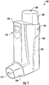
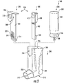
- a metered-dose inhaler (MDI) 100 includes an actuator 200, a canister 300, and a dose counter 150 that includes a circuit assembly 400 and a triggering unit 500.
- the actuator 200 includes a housing 202 that has a canister portion 204 with an opening 206 for receiving the canister 300 therein, and a dispensing portion 208 that includes an opening 210 for dispensing a metered amount of a pharmaceutical formulation.
- the actuator 200 further includes a bottom wall 212, a top opening 214 and a stem block 216.
- the canister 300 includes a can or vial 302 with a top end 304 and a bottom end 306.
- the canister 300 further includes a valve stem 308 at the bottom end 306.
- the MDI 100 When the canister 300 is positioned in the actuator 200, the MDI 100 is actuated when a user presses the vial top end 304 so that the valve stem 308 contacts the bottom wall 212 of the housing 202.
- the valve stem 308 is pressed in a direction toward the vial 302, which then dispenses a metered-dose of the pharmaceutical formulation.
- the actuator 200 includes an interior sleeve or stem block 216 ( Figures 3-5 ) that cooperates with the valve stem 308 to guide the valve stem 308 into a depressed position.
- the pharmaceutical formation exits the actuator 200 via the opening 210, which is sized and configured so that a user can position the opening 210 in his or her mouth or through another drug delivery device to inhale the dispensed dose.
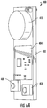
- the circuit assembly 400 includes a substrate 402 with a counting circuit 404, two spatially-offset switches 406, 408 and a battery 410 on one side ( Figure 6A ), and a display 412 on an opposing side ( Figure 6B ).
- the tr iggering unit 500 includes a body 502 with a top portion 504 and a bottom portion 512.
- the top portion 504 includes an overhanging portion 506 that forms an inverted U-shape and defines a recessed opening 508 and further includes a display opening 510.
- the bottom portion 512 includes at least two protruding finger members 514, 516 that are connected, respectively, to at least two trigger members 518, 520.
- the circuit assembly 400 is positioned in the recessed opening 508 of the triggering unit 500 so that the display 412 is visible to the user through the display opening 510 of the triggering unit 500.
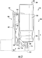
- the circuit assembly 400 and the triggering unit 500 are positioned in the actuator 200 adjacent the canister 300 so that the protruding finger members 514, 516 of the triggering unit 500 are at the bottom end 306 of the vial 302 in an at rest position ( Figure 3 ).
- the trigger members 518, 520 are in a rest position in which the trigger members 518, 520 do not interact with or trigger the switches 406, 408 on the circuit assembly 400.
- the canister 300 is moved in a longitudinal direction of arrow A as shown in Figure 4 , the canister bottom end 306 engages with the finger member 516 so that the trigger member 520 depresses and engages the switch 408.
- the finger member 516 is moved in a lateral direction by the canister 300 so that the trigger member 520 also moves in the lateral direction to depress the switch 408.
- the canister bottom end 306 engages with the other finger member 514 so that the finger member 514 moves in the lateral direction and the trigger member 518 depresses and engages the switch 406.
- the valve stem 308 also contacts the bottom wall 212 of the housing 202 and dispenses the pharmaceutical formulation.
- the trigger members 518, 520 are spatially offset in the longitudinal direction so that, when the canister 300 is actuated, the trigger member 520 triggers the switch 408 at a first time, and then the trigger member 518 triggers the switch 406 at a second time that is subsequent to the first time.
- the switches 406, 408 are likewise spatially offset to generally align with the trigger members 518, 520. Therefore, during actuation of the canister 300, the switches 406, 408 are activated successively at two different times based on the longitudinal offset between the trigger members 518, 520 and the switches 406, 408. The time difference between the activation of the switches 406, 408 may be used to determine whether sufficient force has been applied to the canister 300 to activate the valve 308.
- the canister 300 is likely moving at a slow rate of speed when the valve 308 is depressed and may be unlikely to dispense a dose. If the time difference between the activation of the switches 406,408 is sufficiently short, then the canister 300 is likely moving at a higher rate of speed so that when the valve 308 is depressed, full activation of the canister 300 and accurate dispensing of the pharmaceutical formulation is achieved.
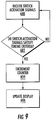
- the activation times of the switches 406, 408 are received as inputs to the counting circuit 404.
- the counting circuit 404 further includes a switch activation timer 450, a counter 452 and a display controller 454.
- the switch activation timer 450 receives the switch activation signals (Block 600; Figure 9 ) and determines whether the switch activation signals satisfy a timing criteria (Block 602 ).
- the timing criteria can be a time difference that is less than a predetermined threshold amount that indicates a successful actuation of the canister 300.
- the threshold amount may be an experimentally determined amount of time that indicates, for example, that the speed at which the canister 300 is depressed is sufficient to actuate the valve 308.
- the timing criteria may also include confirming that both switches 406, 408 have been activated. If the timing criteria are met at Block 602 , then the switch activation timer 450 increments counting indicia at the counter 452 to indicate that a dose has been dispensed (Block 604 ). The display controller 454 receives the counting information from the switch activation timer 450 and/or the counter 452 and updates the display 412 (Block 606 ). The counter 452 may increment counting indicia in either a positive or negative direction.
- valve stem 308 is generally at a fully depressed position such that the valve stem 308 is at the bottom wall 212 of the actuator 200 to dispense the pharmaceutical formulation provided that the valve stem 308 has been depressed with sufficient force and/or speed. Accordingly, the activation of the second switch 408 indicates that the valve stem 308 has reached the depressed position. In this configuration, the timing of the activation of the switches 406, 408 combined with the depressed position of the valve stem 308 indicated when the second switch 408 is activated may be used to determine whether the pharmaceutical formulation has been dispensed.
- the body portion 502 of the triggering unit 500 is configured to be received in the actuator housing 202 between a wall of the housing 202 and the canister 300.
- the circuit assembly 400 may be positioned between the triggering unit body portion 502 and the wall of the actuation housing 202.
- the circuit assembly 400 and the triggering unit 500 may be positioned in the actuator 200 without generally requiring significant changes to the dimensions of the actuator 200 so that the look and feel of the actuator 200 is similar or identical to conventional actuator/canister assemblies. Accordingly, the circuit assembly 400 and the triggering unit 500 may be incorporated into the actuator 200 without substantially changing operation of the inhaler 100 by the user to potentially increase user acceptance and ease of use.
- a dose counter 150 that includes the circuit assembly 400 and the triggering unit 500
- various modifications of the dose counter 150 are within the scope of the invention.
- the circuit assembly 400 and the triggering unit 500 may be rigidly connected to one another and/or provided as a single unit.
Landscapes
- Health & Medical Sciences (AREA)
- Engineering & Computer Science (AREA)
- Life Sciences & Earth Sciences (AREA)
- Anesthesiology (AREA)
- Bioinformatics & Cheminformatics (AREA)
- Pulmonology (AREA)
- Biomedical Technology (AREA)
- Heart & Thoracic Surgery (AREA)
- Hematology (AREA)
- Animal Behavior & Ethology (AREA)
- General Health & Medical Sciences (AREA)
- Public Health (AREA)
- Veterinary Medicine (AREA)
- Biophysics (AREA)
- Infusion, Injection, And Reservoir Apparatuses (AREA)
Claims (18)
- Dosiszähler (150) für einen Dosierinhalator (100), der ein Betätigungsgehäuse und einen Behälter (300) mit einem Betätigungsventil an einem Ventilende des Behälters aufweist, wobei der Behälter ausgebildet ist, in dem Betätigungsgehäuse aufgenommen zu werden und sich von einer Ruheposition in eine Betätigungsposition zu bewegen, in der das Ventil gegen einen Bodenbereich des Betätigungsgehäuses gedrückt wird, wobei der Dosiszähler umfasst:eine Auslöseeinheit (500), auf der mindestens ein erstes und ein zweites Auslöseelement angeordnet sind, wobei die Auslöseeinheit ausgebildet ist, mit dem Behälter zusammenzuwirken, wenn sich der Behälter in eine Längsrichtung von der Ruheposition in die Betätigungsposition bewegt;eine Schaltungsanordnung (400) umfassend ein Trägermaterial, auf dem mindestens ein erster und ein zweiter Schalter (406, 408) angeordnet sind, wobei die ersten und zweiten Schalter ausgebildet sind, mit den ersten und zweiten Auslöseelementen (518, 520) zusammenzuwirken, wenn sich der Behälter von der Ruheposition in die Betätigungsposition bewegt, so dass das erste Auslöseelement den ersten Schalter auslöst, wenn der Behälter eine erste Längsposition erreicht und das zweite Auslöseelement den zweiten Schalter auslöst, wenn der Behälter eine zweite Längsposition während der Bewegung des Behälters von der Ruheposition zu der Betätigungsposition erreicht, wobei sich die zweite Längsposition von der ersten Längsposition unterscheidet;wobei die ersten und zweiten Auslöseelemente ausgebildet sind, sich von einer ersten Position in eine zweite Position zu bewegen, um die ersten und zweiten Schalter zu betätigen, wenn sich der Behälter in Längsrichtung bewegt; unddie Schaltungsanordnung weiter eine Zählschaltung (404) umfasst, die ausgebildet ist, ein Signal von den ersten und zweiten Schaltern zu empfangen, das mindestens einen ersten Zeitpunkt kennzeichnet, wenn der erste Schalter durch das erste Auslöseelement ausgelöst wird und einen zweiten Zeitpunkt kennzeichnet, wenn der zweite Schalter durch das zweite Auslöseelement ausgelöst wird, und die ausgebildet ist, basierend auf dem ersten und zweiten Zeitpunkt festzustellen, wenn der Dosierinhalator betätigt wird,dadurch gekennzeichnet, dassdie Zählschaltung (404) ausgebildet ist, festzustellen, ob der Dosierinhalator betätigt wird, wenn eine Zeitdifferenz zwischen dem ersten und dem zweiten Zeitpunkt einen Schwellenwert unterschreitet.
- Der Dosiszähler gemäß Patenanspruch 1, wobei die Auslöseeinheit (500) erste und zweite Fingerelemente (514, 516) umfasst, die in Wirkverbindung mit dem ersten beziehungsweise dem zweiten Auslöseelement (518, 520) stehen, wobei das erste Fingerelement ausgebildet ist, das erste Auslöseelement in eine Querrichtung zu bewegen, wenn der Behälter die erste Längsposition erreicht und das zweite Fingerelement ausgebildet ist, das zweite Auslöseelement in die Querrichtung zu bewegen, wenn der Behälter die zweite Längsposition erreicht.
- Der Dosiszähler gemäß Patenanspruch 2, wobei die zweite Längsposition des Behälters eine Position ist, in der das Ventil gegen den Bodenbereich des Betätigungsgehäuses gedrückt wird.
- Der Dosiszähler gemäß Patenanspruch 1, wobei die Auslöseeinheit ein Körperteil (512) umfasst, das ausgebildet ist, in dem Betätigungsgehäuse zwischen einer Wand des Betätigungsgehäuses und dem Behälter (300) positioniert zu werden.
- Der Dosiszähler gemäß Patenanspruch 4, wobei sich die ersten und zweiten Fingerelemente (514, 516) in der ersten Position in Richtung des Behälters erstrecken, wenn die Auslöseeinheit in dem Betätigungsgehäuse zwischen der Wand des Betätigungsgehäuses und dem Behälter positioniert ist und sich die ersten und zweiten Fingerelemente (514, 516) in eine Querrichtung in Richtung der Wand des Betätigungsgehäuses in die zweite Position bewegen.
- Der Dosiszähler gemäß Patenanspruch 5, wobei die ersten und zweiten Fingerelemente der Auslöseeinheit in die erste Position gelenkt werden, wenn der Behälter in der Ruheposition ist.
- Der Dosiszähler gemäß Patenanspruch 4, wobei die Schaltungsanordnung ausgebildet ist, zwischen dem Körperteil der Auslöseeinheit und der Wand des Betätigungsgehäuses positioniert zu werden.
- Der Dosiszähler gemäß Patenanspruch 7, wobei die ersten und zweiten Schalter auf einer ersten Seite des Trägermaterials der Schaltungsanordnung angeordnet sind und, die Schaltungsanordnung weiter eine Anzeige auf einer zweiten, gegenüberliegenden Seite des Trägermaterials der Schaltungsanordnung aufweist.
- Der Dosiszähler gemäß Patenanspruch 8, wobei die Zählschaltung einen Zählstand erhöht und den Zählstand auf der Anzeige anzeigt, wenn die Zählschaltung basierend auf dem ersten und zweiten Zeitpunkt feststellt, dass der Dosierinhalator betätigt wird.
- Der Dosiszähler gemäß Patenanspruch 8, wobei die Anzeige eine Anzeige auf Basis von elektronischer Tinte ist.
- Der Dosiszähler gemäß Patenanspruch 5, wobei das Körperteil der Auslöseeinheit ein erstes Ende und ein gegenüberliegendes zweites Ende hat, wobei die Fingerelemente auf dem ersten Ende sind und die Auslöseeinheit weiter ein überhängendes Element umfasst, das eine ausgesparte Öffnung definiert, die ausgebildet ist, die Zählschaltungsanordnung aufzunehmen.
- Der Dosiszähler gemäß Patenanspruch 11, wobei das überhängende Element weiter eine Anzeigenöffnung umfasst, um die Anzeige darin aufzunehmen, so dass die Anzeige für einen Nutzer sichtbar ist.
- Der Dosiszähler gemäß Patenanspruch 1, wobei die Zählschaltung (404) auf dem Trägermaterial der Schaltungsanordnung (400) positioniert ist.
- Eine Dosierinhalatoranordnung (100) umfassend:einen Dosierinhalator, der ein Betätigungsgehäuse (202) und einen Behälter mit einem Betätigungsventil an einem Ventilende des Kanisters (300) aufweist, wobei der Kanister ausgebildet ist, in dem Betätigungsgehäuse aufgenommen zu werden und sich von einer Ruheposition in eine Betätigungsposition zu bewegen, in welcher das Ventil gegen einen Bodenbereich des Betätigungsgehäuses gedrückt wird;ein Dosiszähler (150) in dem Betätigungsgehäuse, wobei der Dosiszähler umfasst:eine Auslöseeinheit, auf der mindestens ein erstes und ein zweites Auslöseelement (518, 520) angeordnet sind, wobei die Auslöseeinheit (500) ausgebildet ist, mit dem Behälter zusammenzuwirken, wenn sich der Behälter in eine Längsrichtung von der Ruheposition in die Betätigungsposition bewegt;wobei die ersten und zweiten Auslöseelemente ausgebildet sind, sich von einer ersten Position in eine zweite Position zu bewegen, um die ersten und zweiten Schalter zu betätigen, wenn sich der Behälter in die Längsrichtung bewegt;eine Schaltungsanordnung (400) die ein Trägerelement, auf dem mindestens ein erster und ein zweiter Schalter (406, 408) angeordnet sind, wobei die ersten und zweiten Schalter ausgebildet sind, mit den ersten und zweiten Auslöseelementen zusammenzuwirken, wenn sich der Behälter von der Ruheposition in die Betätigungsposition bewegt, so dass das erste Auslöseelement den ersten Schalter auslöst, wenn der Behälter eine erste Längsposition erreicht, und das zweite Auslöseelement den zweiten Schalter auslöst, wenn der Behälter eine zweite Längsposition während der Bewegung des Behälters von der Ruheposition in die Betätigungsposition erreicht, wobei sich die zweite Längsposition von der ersten Längsposition unterscheidet; undeine Zählschaltung (404) die ausgebildet ist, ein Signal von den ersten und zweiten Schaltern (406, 408) zu empfangen, das wenigstens einen ersten Zeitpunkt kennzeichnet, wenn der erste Schalter durch das erste Auslöseelement ausgelöst wird und einen zweiten Zeitpunkt kennzeichnet, wenn der zweite Schalter durch das zweite Auslöseelement ausgelöst wird, und ausgebildet ist, basierend auf dem ersten und zweiten Zeitpunkte festzustellen, wenn der Dosierinhalator aktiviert wird, wobei die Zählschaltung ausgebildet ist, festzustellen, ob der Dosierinhalator betätigt wird, wenn eine Zeitdifferenz zwischen dem ersten und dem zweiten Zeitpunkt einen Schwellenwert unterschreitet.
- Die Dosierinhalatoranordnung gemäß Patentanspruch 14, wobei die Auslöseeinheit erste und zweite Fingerelemente umfasst, die in Wirkverbindung mit dem ersten beziehungsweise dem zweiten Auslöseelement stehen, wobei das erste Fingerelement ausgebildet ist, das erste Auslöseelement in einer Querrichtung zu bewegen, wenn der Behälter die erste Längsposition erreicht, und das zweite Fingerelement ausgebildet ist, das zweite Auslöseelement in die Querrichtung zu bewegen, wenn der Behälter die zweite Längsposition erreicht.
- Die Dosierinhalatoranordnung gemäß Patentanspruch 15, wobei die zweite Längsposition des Kanisters eine Position ist, in der das Ventil gegen einen Bodenbereich des Betätigungsgehäuses gedrückt wird.
- Die Dosierinhalatoranordnung gemäß Patentanspruch 14, wobei die Auslöseeinheit ein Körperteil umfasst, das ausgebildet ist, in dem Betätigungsgehäuse zwischen einer Wand des Betätigungsgehäuses und dem Behälter positioniert zu werden.
- Die Dosierinhalatoranordnung gemäß Patentanspruch 17, wobei sich die ersten und zweiten Fingerelemente in der ersten Position in Richtung des Behälters erstrecken und sich in eine Querrichtung in Richtung der Wand des Betätigungsgehäuses in die zweite Position bewegen, wenn die Auslöseeinheit in dem Betätigungsgehäuse zwischen der Wand des Betätigungsgehäuses und dem Behälter positioniert sind.
Applications Claiming Priority (2)
| Application Number | Priority Date | Filing Date | Title |
|---|---|---|---|
| US201462042437P | 2014-08-27 | 2014-08-27 | |
| PCT/IB2015/056477 WO2016030844A1 (en) | 2014-08-27 | 2015-08-26 | Metered-dose inhaler counter with switch and metered-dose inhaler including such a counter |
Publications (2)
| Publication Number | Publication Date |
|---|---|
| EP3125980A1 EP3125980A1 (de) | 2017-02-08 |
| EP3125980B1 true EP3125980B1 (de) | 2017-09-27 |
Family
ID=54065422
Family Applications (1)
| Application Number | Title | Priority Date | Filing Date |
|---|---|---|---|
| EP15760292.1A Active EP3125980B1 (de) | 2014-08-27 | 2015-08-26 | Zähler für inhalator mit abgemessener dosis mit schalter und inhalator mit abgemessener dosis mit solch einem zähler |
Country Status (4)
| Country | Link |
|---|---|
| US (1) | US9943656B2 (de) |
| EP (1) | EP3125980B1 (de) |
| ES (1) | ES2645292T3 (de) |
| WO (1) | WO2016030844A1 (de) |
Families Citing this family (16)
| Publication number | Priority date | Publication date | Assignee | Title |
|---|---|---|---|---|
| ES2708855T5 (en) | 2016-09-30 | 2025-03-27 | Presspart Gmbh & Co Kg | Metered dose inhaler for dispensing aerosol doses |
| EP3552646B1 (de) | 2016-11-18 | 2021-07-07 | Norton (Waterford) Limited | Arzneimittelabgabevorrichtung mit elektronik |
| EP3363485B1 (de) | 2017-02-20 | 2022-04-20 | Presspart Gmbh & Co. Kg | Dosierinhalator |
| EP3431127B1 (de) | 2017-07-18 | 2021-01-20 | Presspart Gmbh & Co. Kg | Dosierinhalator |
| ES2875352T3 (es) | 2017-11-20 | 2021-11-10 | Presspart Gmbh & Co Kg | Sistema de inhalación |
| USD882754S1 (en) | 2017-12-20 | 2020-04-28 | Presspart Gmbh & Co. Kg | Inhaler |
| WO2020225666A1 (en) * | 2019-05-07 | 2020-11-12 | 3M Innovative Properties Company | Warning system, inhaler, and method for generating warning |
| JP7502336B2 (ja) | 2019-05-17 | 2024-06-18 | ノートン (ウォーターフォード) リミテッド | 電子機器を有する薬送達デバイス |
| WO2021007154A1 (en) | 2019-07-05 | 2021-01-14 | Norton (Waterford) Limited | Drug delivery device with electronics and power management |
| CA195581S (en) * | 2019-11-18 | 2022-03-11 | Vectura Delivery Devices Ltd | Monitor for an inhaler |
| CN114787820A (zh) | 2019-12-10 | 2022-07-22 | 鲁德尔国际医疗公司 | 集成式剂量计数器 |
| EP3940677A1 (de) | 2020-07-17 | 2022-01-19 | Presspart Gmbh & Co. Kg | Medikamentenbehälter und medikamentenabgabevorrichtung |
| USD991440S1 (en) * | 2020-11-05 | 2023-07-04 | Adherium (Nz) Limited | Compliance monitor for metered dose inhaler |
| IT202100006854A1 (it) * | 2021-03-22 | 2022-09-22 | Palladio Group S P A | Dispositivo di attribuzione elettronica per medicinali |
| EP4173661A1 (de) * | 2021-10-28 | 2023-05-03 | Aptar Radolfzell GmbH | Auswertungseinheit für einen medikamentenspender sowie set aus einer auswertungseinheit und einem medikamentenspender |
| DE102024134851A1 (de) * | 2024-11-26 | 2026-05-28 | Schreiner Group Gmbh & Co. Kg | Elektronische Verpackungseinheit, System und Verfahren zum Herstellen eines Systems mit einer elektronischen Verpackungseinheit |
Family Cites Families (7)
| Publication number | Priority date | Publication date | Assignee | Title |
|---|---|---|---|---|
| US5505195A (en) | 1993-09-16 | 1996-04-09 | Medtrac Technologies Inc. | Dry powder inhalant device with dosage and air flow monitor |
| SE9801115D0 (sv) * | 1998-03-30 | 1998-03-30 | Astra Ab | Electrical device |
| GB0026646D0 (en) * | 2000-10-31 | 2000-12-13 | Glaxo Group Ltd | Medicament dispenser |
| US20040255936A1 (en) | 2003-04-30 | 2004-12-23 | David Urbanus | Disposable metered dose inhaler with integrated electronic counter |
| US20050028815A1 (en) * | 2003-07-23 | 2005-02-10 | Deaton Daniel M. | Apparatus for electronic dosage counter |
| GB0518770D0 (en) * | 2005-09-14 | 2005-10-26 | Glaxo Group Ltd | A closure for a dispensing device |
| GB2470188B (en) | 2009-05-11 | 2011-06-22 | Consort Medical Plc | Improvements in or relating to dispensing apparatus and dose counters |
-
2015
- 2015-08-26 US US15/311,098 patent/US9943656B2/en active Active
- 2015-08-26 ES ES15760292.1T patent/ES2645292T3/es active Active
- 2015-08-26 EP EP15760292.1A patent/EP3125980B1/de active Active
- 2015-08-26 WO PCT/IB2015/056477 patent/WO2016030844A1/en not_active Ceased
Non-Patent Citations (1)
| Title |
|---|
| None * |
Also Published As
| Publication number | Publication date |
|---|---|
| US20170087312A1 (en) | 2017-03-30 |
| US9943656B2 (en) | 2018-04-17 |
| WO2016030844A1 (en) | 2016-03-03 |
| ES2645292T3 (es) | 2017-12-04 |
| EP3125980A1 (de) | 2017-02-08 |
Similar Documents
| Publication | Publication Date | Title |
|---|---|---|
| US9943656B2 (en) | Metered-dose inhaler counter with switch and metered-dose inhaler including such a counter | |
| US20180221600A1 (en) | Metered-Dose Inhaler Counter (MDI) with Lateral Switches and Metered-Does Inhaler Including such a Counter | |
| AU2004259032B2 (en) | Apparatus for electronic dosage counter | |
| US20060254581A1 (en) | Dose counting in metered dose inhaler | |
| EP3363485B1 (de) | Dosierinhalator | |
| TW499313B (en) | Lockout mechanism for aerosol drug delivery devices | |
| US6360739B1 (en) | Dispenser with doses counter | |
| US9872964B2 (en) | Metered dose inhaler counter and metered-dose inhaler including such a counter | |
| EP3300753B1 (de) | Dosierinhalator zur abgabe von dosen eines aerosols | |
| US20040255936A1 (en) | Disposable metered dose inhaler with integrated electronic counter | |
| JP2007524435A (ja) | 内部医薬リザーバの状態を表すディスプレイを有する医薬分与装置 | |
| EP2953673A1 (de) | Dosier-inhalator mit einem elektronischen dosiszähler | |
| WO2020225570A1 (en) | Improvements relating to inhalers | |
| CN108452409B (zh) | 定量吸入器 | |
| WO2020163473A1 (en) | Dose feedback mechanisms and assemblies for user feedback | |
| GB2505209A (en) | Metered-dose inhaler and counter | |
| WO2007045475A1 (en) | Dose counting device |
Legal Events
| Date | Code | Title | Description |
|---|---|---|---|
| PUAI | Public reference made under article 153(3) epc to a published international application that has entered the european phase |
Free format text: ORIGINAL CODE: 0009012 |
|
| 17P | Request for examination filed |
Effective date: 20161102 |
|
| AK | Designated contracting states |
Kind code of ref document: A1 Designated state(s): AL AT BE BG CH CY CZ DE DK EE ES FI FR GB GR HR HU IE IS IT LI LT LU LV MC MK MT NL NO PL PT RO RS SE SI SK SM TR |
|
| AX | Request for extension of the european patent |
Extension state: BA ME |
|
| GRAP | Despatch of communication of intention to grant a patent |
Free format text: ORIGINAL CODE: EPIDOSNIGR1 |
|
| DAV | Request for validation of the european patent (deleted) | ||
| DAX | Request for extension of the european patent (deleted) | ||
| INTG | Intention to grant announced |
Effective date: 20170607 |
|
| GRAS | Grant fee paid |
Free format text: ORIGINAL CODE: EPIDOSNIGR3 |
|
| GRAA | (expected) grant |
Free format text: ORIGINAL CODE: 0009210 |
|
| AK | Designated contracting states |
Kind code of ref document: B1 Designated state(s): AL AT BE BG CH CY CZ DE DK EE ES FI FR GB GR HR HU IE IS IT LI LT LU LV MC MK MT NL NO PL PT RO RS SE SI SK SM TR |
|
| REG | Reference to a national code |
Ref country code: GB Ref legal event code: FG4D |
|
| REG | Reference to a national code |
Ref country code: CH Ref legal event code: EP |
|
| REG | Reference to a national code |
Ref country code: AT Ref legal event code: REF Ref document number: 931417 Country of ref document: AT Kind code of ref document: T Effective date: 20171015 |
|
| REG | Reference to a national code |
Ref country code: IE Ref legal event code: FG4D |
|
| REG | Reference to a national code |
Ref country code: CH Ref legal event code: NV Representative=s name: R.A. EGLI AND CO, PATENTANWAELTE, CH |
|
| REG | Reference to a national code |
Ref country code: DE Ref legal event code: R096 Ref document number: 602015005042 Country of ref document: DE |
|
| REG | Reference to a national code |
Ref country code: ES Ref legal event code: FG2A Ref document number: 2645292 Country of ref document: ES Kind code of ref document: T3 Effective date: 20171204 |
|
| PG25 | Lapsed in a contracting state [announced via postgrant information from national office to epo] |
Ref country code: SE Free format text: LAPSE BECAUSE OF FAILURE TO SUBMIT A TRANSLATION OF THE DESCRIPTION OR TO PAY THE FEE WITHIN THE PRESCRIBED TIME-LIMIT Effective date: 20170927 Ref country code: FI Free format text: LAPSE BECAUSE OF FAILURE TO SUBMIT A TRANSLATION OF THE DESCRIPTION OR TO PAY THE FEE WITHIN THE PRESCRIBED TIME-LIMIT Effective date: 20170927 Ref country code: LT Free format text: LAPSE BECAUSE OF FAILURE TO SUBMIT A TRANSLATION OF THE DESCRIPTION OR TO PAY THE FEE WITHIN THE PRESCRIBED TIME-LIMIT Effective date: 20170927 Ref country code: HR Free format text: LAPSE BECAUSE OF FAILURE TO SUBMIT A TRANSLATION OF THE DESCRIPTION OR TO PAY THE FEE WITHIN THE PRESCRIBED TIME-LIMIT Effective date: 20170927 Ref country code: NO Free format text: LAPSE BECAUSE OF FAILURE TO SUBMIT A TRANSLATION OF THE DESCRIPTION OR TO PAY THE FEE WITHIN THE PRESCRIBED TIME-LIMIT Effective date: 20171227 |
|
| REG | Reference to a national code |
Ref country code: NL Ref legal event code: MP Effective date: 20170927 |
|
| REG | Reference to a national code |
Ref country code: LT Ref legal event code: MG4D |
|
| REG | Reference to a national code |
Ref country code: AT Ref legal event code: MK05 Ref document number: 931417 Country of ref document: AT Kind code of ref document: T Effective date: 20170927 |
|
| PG25 | Lapsed in a contracting state [announced via postgrant information from national office to epo] |
Ref country code: LV Free format text: LAPSE BECAUSE OF FAILURE TO SUBMIT A TRANSLATION OF THE DESCRIPTION OR TO PAY THE FEE WITHIN THE PRESCRIBED TIME-LIMIT Effective date: 20170927 Ref country code: RS Free format text: LAPSE BECAUSE OF FAILURE TO SUBMIT A TRANSLATION OF THE DESCRIPTION OR TO PAY THE FEE WITHIN THE PRESCRIBED TIME-LIMIT Effective date: 20170927 Ref country code: GR Free format text: LAPSE BECAUSE OF FAILURE TO SUBMIT A TRANSLATION OF THE DESCRIPTION OR TO PAY THE FEE WITHIN THE PRESCRIBED TIME-LIMIT Effective date: 20171228 Ref country code: BG Free format text: LAPSE BECAUSE OF FAILURE TO SUBMIT A TRANSLATION OF THE DESCRIPTION OR TO PAY THE FEE WITHIN THE PRESCRIBED TIME-LIMIT Effective date: 20171227 |
|
| PG25 | Lapsed in a contracting state [announced via postgrant information from national office to epo] |
Ref country code: NL Free format text: LAPSE BECAUSE OF FAILURE TO SUBMIT A TRANSLATION OF THE DESCRIPTION OR TO PAY THE FEE WITHIN THE PRESCRIBED TIME-LIMIT Effective date: 20170927 |
|
| PG25 | Lapsed in a contracting state [announced via postgrant information from national office to epo] |
Ref country code: CZ Free format text: LAPSE BECAUSE OF FAILURE TO SUBMIT A TRANSLATION OF THE DESCRIPTION OR TO PAY THE FEE WITHIN THE PRESCRIBED TIME-LIMIT Effective date: 20170927 |
|
| PG25 | Lapsed in a contracting state [announced via postgrant information from national office to epo] |
Ref country code: SM Free format text: LAPSE BECAUSE OF FAILURE TO SUBMIT A TRANSLATION OF THE DESCRIPTION OR TO PAY THE FEE WITHIN THE PRESCRIBED TIME-LIMIT Effective date: 20170927 Ref country code: EE Free format text: LAPSE BECAUSE OF FAILURE TO SUBMIT A TRANSLATION OF THE DESCRIPTION OR TO PAY THE FEE WITHIN THE PRESCRIBED TIME-LIMIT Effective date: 20170927 Ref country code: AT Free format text: LAPSE BECAUSE OF FAILURE TO SUBMIT A TRANSLATION OF THE DESCRIPTION OR TO PAY THE FEE WITHIN THE PRESCRIBED TIME-LIMIT Effective date: 20170927 Ref country code: IS Free format text: LAPSE BECAUSE OF FAILURE TO SUBMIT A TRANSLATION OF THE DESCRIPTION OR TO PAY THE FEE WITHIN THE PRESCRIBED TIME-LIMIT Effective date: 20180127 Ref country code: SK Free format text: LAPSE BECAUSE OF FAILURE TO SUBMIT A TRANSLATION OF THE DESCRIPTION OR TO PAY THE FEE WITHIN THE PRESCRIBED TIME-LIMIT Effective date: 20170927 |
|
| REG | Reference to a national code |
Ref country code: DE Ref legal event code: R097 Ref document number: 602015005042 Country of ref document: DE |
|
| PG25 | Lapsed in a contracting state [announced via postgrant information from national office to epo] |
Ref country code: DK Free format text: LAPSE BECAUSE OF FAILURE TO SUBMIT A TRANSLATION OF THE DESCRIPTION OR TO PAY THE FEE WITHIN THE PRESCRIBED TIME-LIMIT Effective date: 20170927 |
|
| PLBE | No opposition filed within time limit |
Free format text: ORIGINAL CODE: 0009261 |
|
| STAA | Information on the status of an ep patent application or granted ep patent |
Free format text: STATUS: NO OPPOSITION FILED WITHIN TIME LIMIT |
|
| REG | Reference to a national code |
Ref country code: FR Ref legal event code: PLFP Year of fee payment: 4 |
|
| PG25 | Lapsed in a contracting state [announced via postgrant information from national office to epo] |
Ref country code: PL Free format text: LAPSE BECAUSE OF FAILURE TO SUBMIT A TRANSLATION OF THE DESCRIPTION OR TO PAY THE FEE WITHIN THE PRESCRIBED TIME-LIMIT Effective date: 20170927 |
|
| 26N | No opposition filed |
Effective date: 20180628 |
|
| PG25 | Lapsed in a contracting state [announced via postgrant information from national office to epo] |
Ref country code: MC Free format text: LAPSE BECAUSE OF FAILURE TO SUBMIT A TRANSLATION OF THE DESCRIPTION OR TO PAY THE FEE WITHIN THE PRESCRIBED TIME-LIMIT Effective date: 20170927 |
|
| REG | Reference to a national code |
Ref country code: CH Ref legal event code: PL |
|
| PG25 | Lapsed in a contracting state [announced via postgrant information from national office to epo] |
Ref country code: CH Free format text: LAPSE BECAUSE OF NON-PAYMENT OF DUE FEES Effective date: 20180831 Ref country code: LI Free format text: LAPSE BECAUSE OF NON-PAYMENT OF DUE FEES Effective date: 20180831 Ref country code: LU Free format text: LAPSE BECAUSE OF NON-PAYMENT OF DUE FEES Effective date: 20180826 |
|
| REG | Reference to a national code |
Ref country code: BE Ref legal event code: MM Effective date: 20180831 |
|
| PG25 | Lapsed in a contracting state [announced via postgrant information from national office to epo] |
Ref country code: BE Free format text: LAPSE BECAUSE OF NON-PAYMENT OF DUE FEES Effective date: 20180831 |
|
| PG25 | Lapsed in a contracting state [announced via postgrant information from national office to epo] |
Ref country code: MT Free format text: LAPSE BECAUSE OF NON-PAYMENT OF DUE FEES Effective date: 20180826 |
|
| PG25 | Lapsed in a contracting state [announced via postgrant information from national office to epo] |
Ref country code: TR Free format text: LAPSE BECAUSE OF FAILURE TO SUBMIT A TRANSLATION OF THE DESCRIPTION OR TO PAY THE FEE WITHIN THE PRESCRIBED TIME-LIMIT Effective date: 20170927 |
|
| PG25 | Lapsed in a contracting state [announced via postgrant information from national office to epo] |
Ref country code: PT Free format text: LAPSE BECAUSE OF FAILURE TO SUBMIT A TRANSLATION OF THE DESCRIPTION OR TO PAY THE FEE WITHIN THE PRESCRIBED TIME-LIMIT Effective date: 20170927 |
|
| PG25 | Lapsed in a contracting state [announced via postgrant information from national office to epo] |
Ref country code: RO Free format text: LAPSE BECAUSE OF FAILURE TO SUBMIT A TRANSLATION OF THE DESCRIPTION OR TO PAY THE FEE WITHIN THE PRESCRIBED TIME-LIMIT Effective date: 20170927 Ref country code: MK Free format text: LAPSE BECAUSE OF NON-PAYMENT OF DUE FEES Effective date: 20170927 Ref country code: CY Free format text: LAPSE BECAUSE OF FAILURE TO SUBMIT A TRANSLATION OF THE DESCRIPTION OR TO PAY THE FEE WITHIN THE PRESCRIBED TIME-LIMIT Effective date: 20170927 Ref country code: HU Free format text: LAPSE BECAUSE OF FAILURE TO SUBMIT A TRANSLATION OF THE DESCRIPTION OR TO PAY THE FEE WITHIN THE PRESCRIBED TIME-LIMIT; INVALID AB INITIO Effective date: 20150826 Ref country code: IE Free format text: LAPSE BECAUSE OF NON-PAYMENT OF DUE FEES Effective date: 20180826 |
|
| PG25 | Lapsed in a contracting state [announced via postgrant information from national office to epo] |
Ref country code: AL Free format text: LAPSE BECAUSE OF FAILURE TO SUBMIT A TRANSLATION OF THE DESCRIPTION OR TO PAY THE FEE WITHIN THE PRESCRIBED TIME-LIMIT Effective date: 20170927 |
|
| PG25 | Lapsed in a contracting state [announced via postgrant information from national office to epo] |
Ref country code: SI Free format text: LAPSE BECAUSE OF NON-PAYMENT OF DUE FEES Effective date: 20180826 |
|
| PGFP | Annual fee paid to national office [announced via postgrant information from national office to epo] |
Ref country code: ES Payment date: 20250917 Year of fee payment: 11 |
|
| PGFP | Annual fee paid to national office [announced via postgrant information from national office to epo] |
Ref country code: DE Payment date: 20250819 Year of fee payment: 11 |
|
| PGFP | Annual fee paid to national office [announced via postgrant information from national office to epo] |
Ref country code: IT Payment date: 20250829 Year of fee payment: 11 |
|
| PGFP | Annual fee paid to national office [announced via postgrant information from national office to epo] |
Ref country code: GB Payment date: 20250822 Year of fee payment: 11 |
|
| PGFP | Annual fee paid to national office [announced via postgrant information from national office to epo] |
Ref country code: FR Payment date: 20250821 Year of fee payment: 11 |