EP3126074B1 - Netz aus drahtringen und verfahren zum herstellen eines netzes aus drahtringen - Google Patents
Netz aus drahtringen und verfahren zum herstellen eines netzes aus drahtringen Download PDFInfo
- Publication number
- EP3126074B1 EP3126074B1 EP15717647.0A EP15717647A EP3126074B1 EP 3126074 B1 EP3126074 B1 EP 3126074B1 EP 15717647 A EP15717647 A EP 15717647A EP 3126074 B1 EP3126074 B1 EP 3126074B1
- Authority
- EP
- European Patent Office
- Prior art keywords
- wire
- strand
- coils
- winding
- mesh
- Prior art date
- Legal status (The legal status is an assumption and is not a legal conclusion. Google has not performed a legal analysis and makes no representation as to the accuracy of the status listed.)
- Not-in-force
Links
Images


Classifications
-
- B—PERFORMING OPERATIONS; TRANSPORTING
- B21—MECHANICAL METAL-WORKING WITHOUT ESSENTIALLY REMOVING MATERIAL; PUNCHING METAL
- B21F—WORKING OR PROCESSING OF METAL WIRE
- B21F31/00—Making meshed-ring network from wire
-
- B—PERFORMING OPERATIONS; TRANSPORTING
- B21—MECHANICAL METAL-WORKING WITHOUT ESSENTIALLY REMOVING MATERIAL; PUNCHING METAL
- B21F—WORKING OR PROCESSING OF METAL WIRE
- B21F15/00—Connecting wire to wire or other metallic material or objects; Connecting parts by means of wire
- B21F15/02—Connecting wire to wire or other metallic material or objects; Connecting parts by means of wire wire with wire
- B21F15/04—Connecting wire to wire or other metallic material or objects; Connecting parts by means of wire wire with wire without additional connecting elements or material, e.g. by twisting
-
- B—PERFORMING OPERATIONS; TRANSPORTING
- B21—MECHANICAL METAL-WORKING WITHOUT ESSENTIALLY REMOVING MATERIAL; PUNCHING METAL
- B21F—WORKING OR PROCESSING OF METAL WIRE
- B21F37/00—Manufacture of rings from wire
-
- E—FIXED CONSTRUCTIONS
- E01—CONSTRUCTION OF ROADS, RAILWAYS, OR BRIDGES
- E01F—ADDITIONAL WORK, SUCH AS EQUIPPING ROADS OR THE CONSTRUCTION OF PLATFORMS, HELICOPTER LANDING STAGES, SIGNS, SNOW FENCES, OR THE LIKE
- E01F7/00—Devices affording protection against snow, sand drifts, side-wind effects, snowslides, avalanches or falling rocks; Anti-dazzle arrangements ; Sight-screens for roads, e.g. to mask accident site
- E01F7/04—Devices affording protection against snowslides, avalanches or falling rocks, e.g. avalanche preventing structures, galleries
- E01F7/045—Devices specially adapted for protecting against falling rocks, e.g. galleries, nets, rock traps
Definitions
- This invention relates to a mesh made of wire rings and a method for making a mesh made of wire rings.
- the mesh according to the invention can advantageously be used as a rockfall barrier and/or as a covering of rock faces.
- this specification refers expressly to the above-mentioned use, the object of the invention may be susceptible to a more general use.
- Meshes made of wire rings are widely used for covering rock slopes to protect the underlying zones from falling masses, flows of detritus and avalanche phenomena.
- These meshes generally consist of a repeated series of wire rings linked to each other, having a diameter normally greater than or equal to 25 cm (centimetres).
- each wire ring is made in the form of a strand with a multi-wire spheroidal cross section, and is obtained by winding and twisting on itself a steel wire along a substantially circular path.
- the wire is closed by splicing at the relative twisting start and finish ends, that is to say, at its two ends.
- the splicing technique even though it is excellent from the point of view of strength, can in no way be automated. In effect, this technique requires a manual processing and an extremely high precision in defining the length of the wire. In addition, if the diameter of the wire is equal to 2 mm the ends of the wire protrude from the strand with the possible injury of personnel involved in the installation of the mesh.
- the clip constitutes an additional element which is relatively expensive and, on the other hand, the size must be selected each time as a function of the quantity of wires twisted and the required strength.
- the aim of this invention is to provide a mesh made of wire rings and a method for making a mesh made of wire rings which overcome the above-mentioned drawbacks.
- the aim of this invention to provide a mesh made of wire rings and a method for making a mesh made of wire rings which are simple compared with the prior art whilst guaranteeing the closing seal of the ring.
- the aim of this invention is to provide a mesh made of wire rings and a method for making a mesh made of wire rings which can be automated.
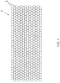
- the numeral 1 denotes in its entirety a mesh made of wire rings, which comprises a repeated series of rings 2 made of wire linked to each other.
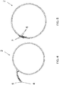
- the mesh 1 comprises a plurality of rings 2 of wire which are linked together, and, as shown more clearly in Figures 2 and 3 , each ring 2 is defined by a strand formed by a steel wire 3 repeatedly wound and twisted on itself in the form of a spiral.
- each ring 2 preferably has a diameter greater than or equal to 25 cm.
- the wire 3 has a first end 4, which is not twisted in the making of the strand, and a second end 5 which is, on the other hand, repeatedly twisted in the form of a spiral in the making of the strand.
- both the ends 4 and 5 are outside the strand ( Figure 4 ) and, according to a distinctive feature of the invention, are both wound in a helical fashion around the strand with the same direction of winding ( Figures 5 and 6 ).
- the first end 4 is, in part, passing through the middle of the rest of the strand in such a way as to protrude outwardly relative to the strand.
- the first end 4 of the wire 3 forms a first helical locking end comprising a plurality of first coils 6 clamped on the strand
- the second end 5 of the wire 3 forms a second helical locking end comprising a plurality of second coils 7 clamped on the strand.
- the first coils 6 and the second coils 7 are alternated with each other.
- This feature makes the ring 2 able to withstand high tensile stresses and, at the same time, easy to make in a mechanised manner.
- the coils of the two windings act in conjunction, blocking each other to make a considerable contribution to the overall resistance of the ring.
- each ring 2 of wire In order to make each ring 2 of wire, the respective wire 3 is wound and twisted repeatedly on itself to form an annular strand from which protrude the two ends 4 and 5 of the wire 3.
- the two ends 4, 5, at the end of this first step, may be in a divergent configuration away from the strand. This would normally be due to the fact that the rigidity of the wire tends to keep the ends 4, 5 protruding from the strand in a configuration tangential to the annular line of extension of the strand.
- This U-shaped configuration may extend in a radial or substantially radial direction relative to the centre of the annular line on which the ring extends, or it may be inclined relative to the radial direction and therefore be partly inclined or resting towards the strand ( Figures 4 and 7 ).
- This positioning alongside each other may occur by bending only one of the two ends 4, 5 or both, in such a way that the two ends 4, 5 adopt both the desired reciprocal configuration (U-shaped) and the desired orientation relative to the strand.
- the ends 4, 5 are wound simultaneously and in a helical fashion around the strand in the same direction of winding.
- the step of simultaneously winding the two ends 4 and 5 of the wire 3 therefore occurs by alternating between them the first coils 6 and the second coils 7.
- the rotational motion with which the two ends 4 and 5 are simultaneously wound is performed preferably and advantageously by a single gripping means, preferably of the gripper type, which grips and moves simultaneously the two ends 4, 5.
- the gripping means (not illustrated) are provided with an orbiting motion about the portion of strand on which the ends 4, 5 of the wire are bent.
- the pickup means are automatic.
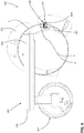
- This invention also relates to a machine 100 for winding rings 2 of wire in such a way as to make a strand as described in the above-mentioned method which is herebelow incorporated in its entirety.
- the machine 100 is illustrated in Figures 8 and 9 and comprises a base 101 for making the strand ( Figure 9 ). More in detail, the base 101 is used to support the strand being formed. Preferably, the base 101 has a horizontal extension.
- the machine 100 comprises an unwinding roller 102 for the wire ( Figure 9 ) rotating around the base 101 according to an annular path for making the rings 2 of wire.
- the machine 100 comprises an element 103 for supporting the unwinding roller 102 extending from a relative central portion 104 positioned at the central (and inner) zone relative to the strand to be formed to a respective lateral portion 105 located at an outer zone relative to the strand to be formed.
- the unwinding roller 102 is connected to the supporting element 103 in such a way that the unwinding of the wire occurs around the base 101.
- the supporting element 103 has a "C" shape lying on a plane transversal (preferably orthogonal) to the base 101 ( Figure 8 ).
- This shape "C” defines advantageously an opening 106 for extracting the strand formed.
- the machine 100 comprises an automatic closing device 107 comprising means 108 for gripping the ends 4, 5 of the wire 3. More specifically, the automatic closing device 107 rotates around the portion of strand over which the ends 4, 5 of the wire 3 are bent in such a way as to wind them around the strand for making the closing.
- the gripping means 108 comprise a toothed wheel 109 having one or more grooves 110 in which the ends 4, 5 of the wire 3 are inserted.
- the machine 100 comprises a second toothed wheel 111 meshing with the first 109 for transmitting the motion to the first. In this way, the first toothed wheel 109 rotates around the strand to wind the ends 4, 5 of the wire around it.
- each ring 2 is made with the same wire 3 which forms the ring 2 and by a single rotational winding movement, which, advantageously, may be mechanised and automated in a simple and inexpensive way.
Landscapes
- Engineering & Computer Science (AREA)
- Mechanical Engineering (AREA)
- Architecture (AREA)
- Civil Engineering (AREA)
- Structural Engineering (AREA)
- Wire Processing (AREA)
- Ropes Or Cables (AREA)
- Input Circuits Of Receivers And Coupling Of Receivers And Audio Equipment (AREA)
Claims (11)
- Netz aus Drahtringen, umfassend eine Vielzahl von Drahtringen (2), die miteinander verknüpft sind, und wobei ein jeder Ring (2) einen Strang umfasst, der aus einem Draht (3) gebildet ist, der wiederholt in einer Spirale um sich selbst gewickelt ist, wobei der Draht (3) ein erstes Ende (4) und ein zweites Ende (5) umfasst, die beide außerhalb des Strangs angeordnet sind, wobei das Netz (1) dadurch gekennzeichnet ist, dass beide Enden (4, 5) des Drahts (3) bei jedem Ring schraubenförmig um den Strang in derselben Wicklungsrichtung gewickelt sind, um den Strang zu schließen.
- Netz nach Anspruch 1, dadurch gekennzeichnet, dass das erste Ende (4) des Drahts (3) ein erstes schraubenförmiges Endverriegelungsteilstück formt, umfassend eine Vielzahl von ersten Spulen (6), die am Strang festgespannt sind, und das zweite Ende (5) des Drahts (3) ein zweites schraubenförmiges Endverriegelungsteilstück formt, umfassend eine Vielzahl von zweiten Spulen (7), die am Strang festgespannt sind, wobei die ersten Spulen (6) und die zweiten Spulen (7) zwischen einander eingesetzt sind.
- Netz nach einem der vorhergehenden Ansprüche, dadurch gekennzeichnet, dass entweder das erste oder das zweite Ende (4; 5) des Drahts (3) vor den jeweiligen Spulen (6; 7), die am Strang festgespannt sind, umgebogen wird.
- Netz nach einem der vorhergehenden Ansprüche, dadurch gekennzeichnet, dass das erste und das zweite Ende (4; 5) des Drahts (3) eine schraubenförmige Verriegelungsvorrichtung formen.
- Netz nach einem der vorhergehenden Ansprüche, dadurch gekennzeichnet, dass das erste und das zweite Ende (4; 5) des Drahts (3) mit einem Wickelschritt um den Strang gewickelt werden, der geringer ist als der Wickelschritt des Drahts (3) um sich selbst, um den Rest des Strangs zu formen.
- Verfahren zum Herstellen eines Netzes aus Drahtringen, wobei ein jeder Ring (2) dadurch hergestellt wird, dass ein Draht (3) wiederholt um sich selbst gewickelt und gewunden wird, um einen ringförmigen Strang zu formen, von dem die zwei Enden (4, 5) des Drahts (3) hervorstehen, dadurch gekennzeichnet, dass die zwei Enden (4, 5) des Drahts (3) hinführend zueinander bewegt und gleichzeitig schraubenförmig um den Strang in derselben Wickelrichtung gewickelt werden, um den Strang zu schließen.
- Verfahren nach Anspruch 6, dadurch gekennzeichnet, dass das erste Ende (4) des Drahts (3) um den Strang gewickelt wird, um ein erstes schraubenförmiges Endverriegelungsteilstück zu formen, umfassend eine Vielzahl von ersten Spulen (6), die am Strang festgespannt sind, und das zweite Ende (5) des Drahts (3) um den Strang gewickelt wird, um ein zweites schraubenförmiges Endverriegelungsteilstück zu formen, umfassend eine Vielzahl von zweiten Spulen (7), die am Strang festgespannt sind, wobei die Enden (4, 5) des Drahts (3) gleichzeitig gewickelt werden, während sie aneinander gehalten werden, sodass die ersten Spulen (6) und die zweiten Spulen (7) zwischen einander eingesetzt werden.
- Verfahren nach Anspruch 7, dadurch gekennzeichnet, dass vor dem Schritt zum gleichzeitigen Wickeln der zwei Enden (4, 5) des Drahts (3) das Umbiegen von mindestens einem der zwei Enden (4; 5) des Drahts (3) stattfindet, um das Ende (4, 5) in die Position entlang des anderen Endes (4, 5) zu bringen, sodass die zwei Enden (4, 5) eine im Wesentlichen U-förmige Konfiguration formen.
- Verfahren nach einem der Ansprüche 6 bis 8, dadurch gekennzeichnet, dass die zwei Enden (4, 5) des Drahts schraubenförmig von einem einzelnen Greifer gewickelt werden, ausgestaltet, um gleichzeitig die zwei Enden (4, 5) zu greifen und eine kreisförmige Bewegung rund um eine Ausdehnungslinie des Strangs durchzuführen.
- Verfahren nach Anspruch 9, dadurch gekennzeichnet, dass der Schritt zum gleichzeitigen Wickeln der zwei Enden (4, 5) automatisch von einer Maschine (100) durchgeführt wird, die den Greifer umfasst.
- Maschine (100), um einen Draht (3) um sich selbst zu wickeln, um einen Strang zu formen, wobei die Maschine (100) umfasst:- eine Basis (101), um den Strang herzustellen;- eine Abrollwalze (102) für den Draht (3), sich drehend um die Basis (101) nach einem ringförmigen Weg zum Herstellen der Ringe (2) aus Draht (3),dadurch gekennzeichnet, dass sie eine automatische Verschließvorrichtung (107) umfasst, umfassend Greifmittel (108), um die Enden (4, 5) des Drahts (3) zu greifen, wobei sich die automatische Verschließvorrichtung (107) um den Strangabschnitt dreht, um den die Enden (4, 5) des Drahts (3) in derselben Richtung wie die Wicklung gebogen werden.
Applications Claiming Priority (2)
| Application Number | Priority Date | Filing Date | Title |
|---|---|---|---|
| ITVR20140079 | 2014-03-31 | ||
| PCT/IB2015/052230 WO2015150987A1 (en) | 2014-03-31 | 2015-03-26 | Mesh made of wire rings and method for making mesh made of wire rings |
Publications (2)
| Publication Number | Publication Date |
|---|---|
| EP3126074A1 EP3126074A1 (de) | 2017-02-08 |
| EP3126074B1 true EP3126074B1 (de) | 2017-07-19 |
Family
ID=50877619
Family Applications (1)
| Application Number | Title | Priority Date | Filing Date |
|---|---|---|---|
| EP15717647.0A Not-in-force EP3126074B1 (de) | 2014-03-31 | 2015-03-26 | Netz aus drahtringen und verfahren zum herstellen eines netzes aus drahtringen |
Country Status (4)
| Country | Link |
|---|---|
| EP (1) | EP3126074B1 (de) |
| AR (1) | AR099889A1 (de) |
| ES (1) | ES2644019T3 (de) |
| WO (1) | WO2015150987A1 (de) |
Families Citing this family (3)
| Publication number | Priority date | Publication date | Assignee | Title |
|---|---|---|---|---|
| FR3083477B1 (fr) * | 2018-05-14 | 2020-06-19 | Compagnie Generale Des Etablissements Michelin | Procede de fabrication d'une tringle tressee pour bandage pneumatique, avec pliage d'un troncon excedentaire du fil de tresse |
| JP2019214862A (ja) * | 2018-06-12 | 2019-12-19 | 前田工繊株式会社 | 複合繊維部材の製造方法、方形部材、及び箱状部材 |
| CN112808892B (zh) * | 2019-11-18 | 2026-03-13 | 宝钢金属有限公司 | 一种切割用的无接头自封闭钢绳绳环 |
Family Cites Families (1)
| Publication number | Priority date | Publication date | Assignee | Title |
|---|---|---|---|---|
| ITMI20031601A1 (it) * | 2003-08-04 | 2005-02-05 | Italgeo S R L | Rete ad anelli di filo, particolarmente per barriere paramassi e rivestimenti di parete rocciose, nonche' procedimento per la realizzazione della rete. |
-
2015
- 2015-03-26 WO PCT/IB2015/052230 patent/WO2015150987A1/en not_active Ceased
- 2015-03-26 EP EP15717647.0A patent/EP3126074B1/de not_active Not-in-force
- 2015-03-26 ES ES15717647.0T patent/ES2644019T3/es active Active
- 2015-03-30 AR ARP150100946A patent/AR099889A1/es active IP Right Grant
Non-Patent Citations (1)
| Title |
|---|
| None * |
Also Published As
| Publication number | Publication date |
|---|---|
| WO2015150987A1 (en) | 2015-10-08 |
| AR099889A1 (es) | 2016-08-24 |
| ES2644019T3 (es) | 2017-11-27 |
| EP3126074A1 (de) | 2017-02-08 |
Similar Documents
| Publication | Publication Date | Title |
|---|---|---|
| EP3126074B1 (de) | Netz aus drahtringen und verfahren zum herstellen eines netzes aus drahtringen | |
| RU2016142676A (ru) | Стальной проволочный трос для конвейерной ленты | |
| RU2011153369A (ru) | Связывающее устройство | |
| KR20160148561A (ko) | 잔류 비틀림이 감소된 스틸 코드 | |
| CN110114165A (zh) | 格状物结构和制造格状物结构的方法 | |
| EP1856346B1 (de) | Verfahren und vorrichtung zur herstellung eines bewehrungsgitters | |
| JP2015524519A5 (de) | ||
| CN105714586B (zh) | 环形吊索及其生产方法和生产装置 | |
| CN1803331A (zh) | 安全网及其制作方法 | |
| EP1504828B1 (de) | Drahtringnetz für eine Schutzvorrichtung für Steinschlag und Verfahren zu seiner Herstellung | |
| MX377894B (es) | Alambre. | |
| KR101675515B1 (ko) | 수목용 로프 연결장치 | |
| US20170028243A1 (en) | Elastic pull rope for use in exercise | |
| US20160236263A1 (en) | Milanese mesh rolling | |
| JP2010185150A (ja) | エンドレススリングの製造方法 | |
| EP3441632A1 (de) | Verbesserte struktur eines fahrradkabelgehäuses | |
| JP4273349B2 (ja) | エンドレススリングの製造方法 | |
| US2107810A (en) | Wire line ends and method of forming same | |
| US3420081A (en) | Chain link fabric fastener | |
| KR101720943B1 (ko) | 와이어로프 슬링의 제조방법 | |
| EP1255623B1 (de) | Maschine und verfahren zum wendelförmigen wickeln eines drahtes um einen ringförmigen kern | |
| KR101765795B1 (ko) | 케이블 비드 와이어의 제조방법 | |
| CN105221657B (zh) | 绳结双钢缆简式链绳的制做方法 | |
| US741177A (en) | Fence-machine. | |
| US1925312A (en) | Wire splicing, stretching, and twisting tool |
Legal Events
| Date | Code | Title | Description |
|---|---|---|---|
| PUAI | Public reference made under article 153(3) epc to a published international application that has entered the european phase |
Free format text: ORIGINAL CODE: 0009012 |
|
| 17P | Request for examination filed |
Effective date: 20161027 |
|
| AK | Designated contracting states |
Kind code of ref document: A1 Designated state(s): AL AT BE BG CH CY CZ DE DK EE ES FI FR GB GR HR HU IE IS IT LI LT LU LV MC MK MT NL NO PL PT RO RS SE SI SK SM TR |
|
| AX | Request for extension of the european patent |
Extension state: BA ME |
|
| GRAP | Despatch of communication of intention to grant a patent |
Free format text: ORIGINAL CODE: EPIDOSNIGR1 |
|
| DAV | Request for validation of the european patent (deleted) | ||
| DAX | Request for extension of the european patent (deleted) | ||
| INTG | Intention to grant announced |
Effective date: 20170220 |
|
| GRAS | Grant fee paid |
Free format text: ORIGINAL CODE: EPIDOSNIGR3 |
|
| GRAA | (expected) grant |
Free format text: ORIGINAL CODE: 0009210 |
|
| AK | Designated contracting states |
Kind code of ref document: B1 Designated state(s): AL AT BE BG CH CY CZ DE DK EE ES FI FR GB GR HR HU IE IS IT LI LT LU LV MC MK MT NL NO PL PT RO RS SE SI SK SM TR |
|
| REG | Reference to a national code |
Ref country code: GB Ref legal event code: FG4D |
|
| REG | Reference to a national code |
Ref country code: CH Ref legal event code: EP |
|
| REG | Reference to a national code |
Ref country code: IE Ref legal event code: FG4D |
|
| REG | Reference to a national code |
Ref country code: AT Ref legal event code: REF Ref document number: 909889 Country of ref document: AT Kind code of ref document: T Effective date: 20170815 |
|
| REG | Reference to a national code |
Ref country code: DE Ref legal event code: R096 Ref document number: 602015003685 Country of ref document: DE |
|
| REG | Reference to a national code |
Ref country code: NL Ref legal event code: MP Effective date: 20170719 |
|
| REG | Reference to a national code |
Ref country code: ES Ref legal event code: FG2A Ref document number: 2644019 Country of ref document: ES Kind code of ref document: T3 Effective date: 20171127 |
|
| REG | Reference to a national code |
Ref country code: LT Ref legal event code: MG4D |
|
| REG | Reference to a national code |
Ref country code: AT Ref legal event code: MK05 Ref document number: 909889 Country of ref document: AT Kind code of ref document: T Effective date: 20170719 |
|
| PG25 | Lapsed in a contracting state [announced via postgrant information from national office to epo] |
Ref country code: HR Free format text: LAPSE BECAUSE OF FAILURE TO SUBMIT A TRANSLATION OF THE DESCRIPTION OR TO PAY THE FEE WITHIN THE PRESCRIBED TIME-LIMIT Effective date: 20170719 Ref country code: FI Free format text: LAPSE BECAUSE OF FAILURE TO SUBMIT A TRANSLATION OF THE DESCRIPTION OR TO PAY THE FEE WITHIN THE PRESCRIBED TIME-LIMIT Effective date: 20170719 Ref country code: LT Free format text: LAPSE BECAUSE OF FAILURE TO SUBMIT A TRANSLATION OF THE DESCRIPTION OR TO PAY THE FEE WITHIN THE PRESCRIBED TIME-LIMIT Effective date: 20170719 Ref country code: NO Free format text: LAPSE BECAUSE OF FAILURE TO SUBMIT A TRANSLATION OF THE DESCRIPTION OR TO PAY THE FEE WITHIN THE PRESCRIBED TIME-LIMIT Effective date: 20171019 Ref country code: NL Free format text: LAPSE BECAUSE OF FAILURE TO SUBMIT A TRANSLATION OF THE DESCRIPTION OR TO PAY THE FEE WITHIN THE PRESCRIBED TIME-LIMIT Effective date: 20170719 Ref country code: AT Free format text: LAPSE BECAUSE OF FAILURE TO SUBMIT A TRANSLATION OF THE DESCRIPTION OR TO PAY THE FEE WITHIN THE PRESCRIBED TIME-LIMIT Effective date: 20170719 Ref country code: SE Free format text: LAPSE BECAUSE OF FAILURE TO SUBMIT A TRANSLATION OF THE DESCRIPTION OR TO PAY THE FEE WITHIN THE PRESCRIBED TIME-LIMIT Effective date: 20170719 |
|
| PG25 | Lapsed in a contracting state [announced via postgrant information from national office to epo] |
Ref country code: LV Free format text: LAPSE BECAUSE OF FAILURE TO SUBMIT A TRANSLATION OF THE DESCRIPTION OR TO PAY THE FEE WITHIN THE PRESCRIBED TIME-LIMIT Effective date: 20170719 Ref country code: IS Free format text: LAPSE BECAUSE OF FAILURE TO SUBMIT A TRANSLATION OF THE DESCRIPTION OR TO PAY THE FEE WITHIN THE PRESCRIBED TIME-LIMIT Effective date: 20171119 Ref country code: GR Free format text: LAPSE BECAUSE OF FAILURE TO SUBMIT A TRANSLATION OF THE DESCRIPTION OR TO PAY THE FEE WITHIN THE PRESCRIBED TIME-LIMIT Effective date: 20171020 Ref country code: BG Free format text: LAPSE BECAUSE OF FAILURE TO SUBMIT A TRANSLATION OF THE DESCRIPTION OR TO PAY THE FEE WITHIN THE PRESCRIBED TIME-LIMIT Effective date: 20171019 Ref country code: PL Free format text: LAPSE BECAUSE OF FAILURE TO SUBMIT A TRANSLATION OF THE DESCRIPTION OR TO PAY THE FEE WITHIN THE PRESCRIBED TIME-LIMIT Effective date: 20170719 Ref country code: RS Free format text: LAPSE BECAUSE OF FAILURE TO SUBMIT A TRANSLATION OF THE DESCRIPTION OR TO PAY THE FEE WITHIN THE PRESCRIBED TIME-LIMIT Effective date: 20170719 |
|
| REG | Reference to a national code |
Ref country code: FR Ref legal event code: PLFP Year of fee payment: 4 |
|
| REG | Reference to a national code |
Ref country code: DE Ref legal event code: R097 Ref document number: 602015003685 Country of ref document: DE |
|
| PG25 | Lapsed in a contracting state [announced via postgrant information from national office to epo] |
Ref country code: DK Free format text: LAPSE BECAUSE OF FAILURE TO SUBMIT A TRANSLATION OF THE DESCRIPTION OR TO PAY THE FEE WITHIN THE PRESCRIBED TIME-LIMIT Effective date: 20170719 Ref country code: CZ Free format text: LAPSE BECAUSE OF FAILURE TO SUBMIT A TRANSLATION OF THE DESCRIPTION OR TO PAY THE FEE WITHIN THE PRESCRIBED TIME-LIMIT Effective date: 20170719 |
|
| PLBE | No opposition filed within time limit |
Free format text: ORIGINAL CODE: 0009261 |
|
| STAA | Information on the status of an ep patent application or granted ep patent |
Free format text: STATUS: NO OPPOSITION FILED WITHIN TIME LIMIT |
|
| PG25 | Lapsed in a contracting state [announced via postgrant information from national office to epo] |
Ref country code: EE Free format text: LAPSE BECAUSE OF FAILURE TO SUBMIT A TRANSLATION OF THE DESCRIPTION OR TO PAY THE FEE WITHIN THE PRESCRIBED TIME-LIMIT Effective date: 20170719 Ref country code: SK Free format text: LAPSE BECAUSE OF FAILURE TO SUBMIT A TRANSLATION OF THE DESCRIPTION OR TO PAY THE FEE WITHIN THE PRESCRIBED TIME-LIMIT Effective date: 20170719 Ref country code: SM Free format text: LAPSE BECAUSE OF FAILURE TO SUBMIT A TRANSLATION OF THE DESCRIPTION OR TO PAY THE FEE WITHIN THE PRESCRIBED TIME-LIMIT Effective date: 20170719 |
|
| 26N | No opposition filed |
Effective date: 20180420 |
|
| PG25 | Lapsed in a contracting state [announced via postgrant information from national office to epo] |
Ref country code: SI Free format text: LAPSE BECAUSE OF FAILURE TO SUBMIT A TRANSLATION OF THE DESCRIPTION OR TO PAY THE FEE WITHIN THE PRESCRIBED TIME-LIMIT Effective date: 20170719 |
|
| REG | Reference to a national code |
Ref country code: DE Ref legal event code: R119 Ref document number: 602015003685 Country of ref document: DE |
|
| REG | Reference to a national code |
Ref country code: CH Ref legal event code: PL |
|
| PG25 | Lapsed in a contracting state [announced via postgrant information from national office to epo] |
Ref country code: MC Free format text: LAPSE BECAUSE OF FAILURE TO SUBMIT A TRANSLATION OF THE DESCRIPTION OR TO PAY THE FEE WITHIN THE PRESCRIBED TIME-LIMIT Effective date: 20170719 |
|
| REG | Reference to a national code |
Ref country code: BE Ref legal event code: MM Effective date: 20180331 |
|
| REG | Reference to a national code |
Ref country code: IE Ref legal event code: MM4A |
|
| PG25 | Lapsed in a contracting state [announced via postgrant information from national office to epo] |
Ref country code: LU Free format text: LAPSE BECAUSE OF NON-PAYMENT OF DUE FEES Effective date: 20180326 |
|
| PG25 | Lapsed in a contracting state [announced via postgrant information from national office to epo] |
Ref country code: IE Free format text: LAPSE BECAUSE OF NON-PAYMENT OF DUE FEES Effective date: 20180326 Ref country code: DE Free format text: LAPSE BECAUSE OF NON-PAYMENT OF DUE FEES Effective date: 20181002 |
|
| PG25 | Lapsed in a contracting state [announced via postgrant information from national office to epo] |
Ref country code: BE Free format text: LAPSE BECAUSE OF NON-PAYMENT OF DUE FEES Effective date: 20180331 Ref country code: CH Free format text: LAPSE BECAUSE OF NON-PAYMENT OF DUE FEES Effective date: 20180331 Ref country code: LI Free format text: LAPSE BECAUSE OF NON-PAYMENT OF DUE FEES Effective date: 20180331 |
|
| GBPC | Gb: european patent ceased through non-payment of renewal fee |
Effective date: 20190326 |
|
| PG25 | Lapsed in a contracting state [announced via postgrant information from national office to epo] |
Ref country code: GB Free format text: LAPSE BECAUSE OF NON-PAYMENT OF DUE FEES Effective date: 20190326 Ref country code: MT Free format text: LAPSE BECAUSE OF NON-PAYMENT OF DUE FEES Effective date: 20180326 |
|
| PG25 | Lapsed in a contracting state [announced via postgrant information from national office to epo] |
Ref country code: TR Free format text: LAPSE BECAUSE OF FAILURE TO SUBMIT A TRANSLATION OF THE DESCRIPTION OR TO PAY THE FEE WITHIN THE PRESCRIBED TIME-LIMIT Effective date: 20170719 |
|
| PG25 | Lapsed in a contracting state [announced via postgrant information from national office to epo] |
Ref country code: PT Free format text: LAPSE BECAUSE OF FAILURE TO SUBMIT A TRANSLATION OF THE DESCRIPTION OR TO PAY THE FEE WITHIN THE PRESCRIBED TIME-LIMIT Effective date: 20170719 |
|
| PG25 | Lapsed in a contracting state [announced via postgrant information from national office to epo] |
Ref country code: CY Free format text: LAPSE BECAUSE OF FAILURE TO SUBMIT A TRANSLATION OF THE DESCRIPTION OR TO PAY THE FEE WITHIN THE PRESCRIBED TIME-LIMIT Effective date: 20170719 Ref country code: RO Free format text: LAPSE BECAUSE OF FAILURE TO SUBMIT A TRANSLATION OF THE DESCRIPTION OR TO PAY THE FEE WITHIN THE PRESCRIBED TIME-LIMIT Effective date: 20170719 Ref country code: MK Free format text: LAPSE BECAUSE OF NON-PAYMENT OF DUE FEES Effective date: 20170719 Ref country code: HU Free format text: LAPSE BECAUSE OF FAILURE TO SUBMIT A TRANSLATION OF THE DESCRIPTION OR TO PAY THE FEE WITHIN THE PRESCRIBED TIME-LIMIT; INVALID AB INITIO Effective date: 20150326 |
|
| PG25 | Lapsed in a contracting state [announced via postgrant information from national office to epo] |
Ref country code: AL Free format text: LAPSE BECAUSE OF FAILURE TO SUBMIT A TRANSLATION OF THE DESCRIPTION OR TO PAY THE FEE WITHIN THE PRESCRIBED TIME-LIMIT Effective date: 20170719 |
|
| PGFP | Annual fee paid to national office [announced via postgrant information from national office to epo] |
Ref country code: FR Payment date: 20230323 Year of fee payment: 9 |
|
| PGFP | Annual fee paid to national office [announced via postgrant information from national office to epo] |
Ref country code: IT Payment date: 20230327 Year of fee payment: 9 |
|
| PGFP | Annual fee paid to national office [announced via postgrant information from national office to epo] |
Ref country code: ES Payment date: 20230424 Year of fee payment: 9 |
|
| PG25 | Lapsed in a contracting state [announced via postgrant information from national office to epo] |
Ref country code: FR Free format text: LAPSE BECAUSE OF NON-PAYMENT OF DUE FEES Effective date: 20240331 |
|
| PG25 | Lapsed in a contracting state [announced via postgrant information from national office to epo] |
Ref country code: FR Free format text: LAPSE BECAUSE OF NON-PAYMENT OF DUE FEES Effective date: 20240331 |
|
| PG25 | Lapsed in a contracting state [announced via postgrant information from national office to epo] |
Ref country code: IT Free format text: LAPSE BECAUSE OF NON-PAYMENT OF DUE FEES Effective date: 20240326 |
|
| REG | Reference to a national code |
Ref country code: ES Ref legal event code: FD2A Effective date: 20250506 |
|
| PG25 | Lapsed in a contracting state [announced via postgrant information from national office to epo] |
Ref country code: ES Free format text: LAPSE BECAUSE OF NON-PAYMENT OF DUE FEES Effective date: 20240327 |