EP3126596B1 - Elektrisches schloss - Google Patents
Elektrisches schloss Download PDFInfo
- Publication number
- EP3126596B1 EP3126596B1 EP14732425.5A EP14732425A EP3126596B1 EP 3126596 B1 EP3126596 B1 EP 3126596B1 EP 14732425 A EP14732425 A EP 14732425A EP 3126596 B1 EP3126596 B1 EP 3126596B1
- Authority
- EP
- European Patent Office
- Prior art keywords
- electric lock
- toothed wheel
- knob
- lock according
- switch
- Prior art date
- Legal status (The legal status is an assumption and is not a legal conclusion. Google has not performed a legal analysis and makes no representation as to the accuracy of the status listed.)
- Active
Links
Images

Classifications
-
- E—FIXED CONSTRUCTIONS
- E05—LOCKS; KEYS; WINDOW OR DOOR FITTINGS; SAFES
- E05B—LOCKS; ACCESSORIES THEREFOR; HANDCUFFS
- E05B63/00—Locks or fastenings with special structural characteristics
- E05B63/04—Locks or fastenings with special structural characteristics for alternative use on the right-hand or left-hand side of wings
-
- E—FIXED CONSTRUCTIONS
- E05—LOCKS; KEYS; WINDOW OR DOOR FITTINGS; SAFES
- E05B—LOCKS; ACCESSORIES THEREFOR; HANDCUFFS
- E05B17/00—Accessories in connection with locks
- E05B17/22—Means for operating or controlling lock or fastening device accessories, i.e. other than the fastening members, e.g. switches, indicators
-
- E—FIXED CONSTRUCTIONS
- E05—LOCKS; KEYS; WINDOW OR DOOR FITTINGS; SAFES
- E05B—LOCKS; ACCESSORIES THEREFOR; HANDCUFFS
- E05B47/00—Operating or controlling locks or other fastening devices by electric or magnetic means
- E05B47/06—Controlling mechanically-operated bolts by electro-magnetically-operated detents
- E05B47/0676—Controlling mechanically-operated bolts by electro-magnetically-operated detents by disconnecting the handle
-
- E—FIXED CONSTRUCTIONS
- E05—LOCKS; KEYS; WINDOW OR DOOR FITTINGS; SAFES
- E05B—LOCKS; ACCESSORIES THEREFOR; HANDCUFFS
- E05B65/00—Locks or fastenings for special use
- E05B65/0032—Locks or fastenings for special use for hotel rooms
-
- E—FIXED CONSTRUCTIONS
- E05—LOCKS; KEYS; WINDOW OR DOOR FITTINGS; SAFES
- E05B—LOCKS; ACCESSORIES THEREFOR; HANDCUFFS
- E05B1/00—Knobs or handles for wings; Knobs, handles, or press buttons for locks or latches on wings
- E05B1/003—Handles pivoted about an axis perpendicular to the wing
-
- E—FIXED CONSTRUCTIONS
- E05—LOCKS; KEYS; WINDOW OR DOOR FITTINGS; SAFES
- E05B—LOCKS; ACCESSORIES THEREFOR; HANDCUFFS
- E05B15/00—Other details of locks; Parts for engagement by bolts of fastening devices
- E05B15/0053—Other details of locks; Parts for engagement by bolts of fastening devices means providing a stable, i.e. indexed, position of lock parts
-
- E—FIXED CONSTRUCTIONS
- E05—LOCKS; KEYS; WINDOW OR DOOR FITTINGS; SAFES
- E05B—LOCKS; ACCESSORIES THEREFOR; HANDCUFFS
- E05B17/00—Accessories in connection with locks
- E05B17/10—Illuminating devices on or for locks or keys; Transparent or translucent lock parts; Indicator lights
-
- E—FIXED CONSTRUCTIONS
- E05—LOCKS; KEYS; WINDOW OR DOOR FITTINGS; SAFES
- E05B—LOCKS; ACCESSORIES THEREFOR; HANDCUFFS
- E05B1/00—Knobs or handles for wings; Knobs, handles, or press buttons for locks or latches on wings
- E05B2001/0076—The handle having at least two operating positions, e.g. the bolt can be retracted by moving the handle either upwards or downwards
-
- E—FIXED CONSTRUCTIONS
- E05—LOCKS; KEYS; WINDOW OR DOOR FITTINGS; SAFES
- E05B—LOCKS; ACCESSORIES THEREFOR; HANDCUFFS
- E05B47/00—Operating or controlling locks or other fastening devices by electric or magnetic means
- E05B2047/0048—Circuits, feeding, monitoring
- E05B2047/005—Opening, closing of the circuit
- E05B2047/0053—Opening, closing of the circuit by operating the handle
-
- E—FIXED CONSTRUCTIONS
- E05—LOCKS; KEYS; WINDOW OR DOOR FITTINGS; SAFES
- E05B—LOCKS; ACCESSORIES THEREFOR; HANDCUFFS
- E05B47/00—Operating or controlling locks or other fastening devices by electric or magnetic means
- E05B2047/0048—Circuits, feeding, monitoring
- E05B2047/0071—Connecting lockparts by electronic communication means only, e.g. bus systems, time multiplexing
-
- E—FIXED CONSTRUCTIONS
- E05—LOCKS; KEYS; WINDOW OR DOOR FITTINGS; SAFES
- E05B—LOCKS; ACCESSORIES THEREFOR; HANDCUFFS
- E05B41/00—Locks with visible indication as to whether the lock is locked or unlocked
Definitions
- the present invention relates to an electric lock.
- the component is generally a card that can contain a microprocessor or be provided with a magnetic strip: in any case its purpose is to store a code associated with the lock to be actuated.
- the door protected with this type of lock, has in general, on the inner side, a first handle associated with a respective spring latch, which always allows the door to be opened from the inside.
- a second handle On the outer side, there is a second handle, which is also associated with a respective spring latch, and a reader that is capable of engaging with the codified component in the user's possession, in order to receive its authorization and enable this second handle and thus the movement of the spring latch.
- Doors provided with electronic locks thus have, generally, on the inner side, a knob, which is capable of disabling the second handle which is outside the door, so that it is possible to prevent access to the room by the service staff, or by anyone who has an accredited codified key.
- the devices that make it possible to disable the second, outer handle of the door are generally complex and are constituted by a plurality of components, with consequent higher probability of malfunctioning that, moreover, involves high maintenance costs, because of the need to disassemble and reassemble the various parts, which are often small.
- WO 89/04413 A1 discloses an operating mechanism for a lock of the type comprising a rotatable operating member and a lock member comprises a primary drive gear arranged to be rotated by rotation of the operating member, a driven gear for connection to the lock member, and a transfer gear for transmitting rotary motion from the drive gear to the driven gear.
- the transfer gear is mounted on a corner plate which rotates with the drive gear when an electromagnet is energised to bring the transfer gear into mesh with the driven gear.
- the aim of the present invention is to solve the above-mentioned drawbacks, by providing an electric lock that is constituted by a reduced number of components.
- an object of the invention is to provide an electric lock that is highly versatile.
- Another object of the present invention is to provide an electric lock which is low-cost, easily and practically implemented and safe in application.
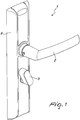
- the reference numeral 1 generally designates an electric lock provided, on the inner side, with a first handle 2 and with a knob 3.
- the lock On the outer side, the lock is provided with a second handle and with an assembly for reading a codified key.
- Such key is generally a card or pass on which, according to different methods, a code associated with the lock to be actuated, is stored.
- the card can be provided with a microprocessor, or a bar code, or be provided with a magnetic strip.
- the user by swiping or inserting the codified key in an adapted seat, or simply by bringing it in the proximity of the reading assembly, enables the second handle, and as a consequence the spring latch, thus gaining access to the room.
- Such second handle is associated with a respective spring latch, and means of mutual decoupling 4 are interposed between the handle and the spring latch.
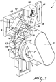
- the electric lock 1 comprises a main body 5 provided with a seat 6 for the rotatable accommodation of a transverse shank 7 of the knob 3.
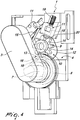
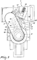
- the decoupling means 4 comprise a contoured disk 8 which is integral with the knob 3, an idle toothed wheel 9 that is provided with a lower profiled plate 10 that constitutes a cam, and a switch 11 facing the edge 12 of the plate 10.
- the contoured disk 8 comprises a toothing 13 that is distributed over a predefined angle and is coupled removably with respective recesses 14 of the toothed wheel 9.
- the rotation of the knob 3 by the user who is inside the room thus causes the rotation of the disk 8 with consequent entrainment of the toothed wheel 9, limited to the predefined angle of the toothing 13, and orientation of the plate 10 that corresponds to its interference with the button 15 of the switch 11.
- the user in order to actuate the switch 11 and prevent access to the room by the service staff, or by anyone who has an accredited codified key, can rotate the knob 3 in both directions, obtaining in any case the necessary coupling between the disk 8 and the toothed wheel 9, and orienting the plate 10 so that it can interfere with the button 15 of the switch 11.
- the contoured disk 8 can be provided with at least two teeth 16 that are arranged over a predefined angle and are coupled removably with respective recesses 14 of the toothed wheel 9.
- the lock 1, according to the invention, can comprise a dynamometric locking device 17 to prevent the accidental rotation of the toothed wheel 9.
- Such device thus prevents an unforeseen rotation, for example owing to the action of the force of gravity on the toothed wheel 9 or on a component connected thereto, such as the knob 3, from causing the actuation of the switch 11, and the consequent inability of the user to access the room.
- the locking device 17 can comprise a pin 18 that is elastically forced on the recesses 14 of the toothed wheel 9 by way of a spring 19 that has an axial action.
- the elastic action of the spring 19 thus causes the locking of the wheel 9 at applied moments of an intensity lower than a preset value.
- the switch 11 is controlled by a mechanical actuator that decouples the second handle from the spring latch.
- the plate 10 has a shape that is preferably selected from an ellipsoid, a shape with an eccentric circumference, and the like.
- the mechanical actuator which decouples the second handle from the spring latch, can be controlled by the assembly for reading a codified key.
- the switch 11 disables the reading assembly.
- the reading assembly cannot disable the mechanical actuator, and thus access to the room by the service staff, or by anyone who has an accredited codified key, is in this manner prevented.
- the lock 1 can comprise a signaling device, that can emit a light beam of differing preset color depending on whether the switch is engaged or otherwise.
- the user once inside the room, when he or she needs to prevent access thereto by other people, rotates the knob 3, in one direction or the other, until the signaling device emits a light beam of a different and preset color.
- the electric lock 1 is constituted by a reduced number of components.
- the electric lock 1, according to the invention is highly versatile.
- the lock 1 can be mounted without any modification or adaptation being necessary.
- the knob 3 can rotate in both directions, thus ensuring in any case the necessary coupling between the disk 8 and the toothed wheel 9, and orienting the plate 10 so that it can interfere with the button 15 of the switch 11.
- the materials employed may be any according to requirements and to the state of the art.
Landscapes
- Engineering & Computer Science (AREA)
- Structural Engineering (AREA)
- Lock And Its Accessories (AREA)
Claims (8)
- Ein elektrisches Schloss, ausgestattet an der Innenseite mit einem ersten Griff (2) und einem Knopf (3) und an der Außenseite mit einem zweiten Griff und einem Aufbau zum Lesen eines kodifizierten Schlüssels; wobei zwischen dem zweiten Griff und einer Zungenfeder Mittel (4) zur gegenseitigen Entkopplung angebracht sind; einem Hauptkörper (5), ausgestattet mit einem Sitz (6) für die drehbare Aufnahme eines Querschafts (7) des Knopfs (3); wobei die Entkopplungsmittel (4) eine konturierte Scheibe (8), ein gezahntes Zwischenrad (9), umfassen, wobei die konturierte Scheibe (8) einen Zahnsatz (13) umfasst, der über einen vordefinierten Winkel verteilt und lösbar mit entsprechenden Vertiefungen (14) in dem Zwischenrad (9) gekoppelt ist; wobei das elektrische Schloss dadurch gekennzeichnet ist, dass die konturierte Scheibe (8) integral mit dem Knopf (3) ist; wobei das Zwischenrad (9) mit einer unteren profilierten Platte (10) ausgestattet ist, die einen Nocken bildet, und das Schloss weiter einen Schalter (11) umfasst, der einer Kante (12) der Platte (10) zugewandt ist; wobei die Drehung des Knopfs (3) die Drehung der Scheibe (8) bestimmt, mit daraus folgender Mitnahme des Zwischenrads (9), begrenzt auf den vordefinierten Winkel des Zahnsatzes (13), und wobei die Ausrichtung der Platte (10) ihrem Eingriff mit einem Knopf (15) des Schalters (11) entspricht, wobei der Schalter (11) den Leseaufbau deaktiviert.
- Das elektrische Schloss gemäß Anspruch 1, dadurch gekennzeichnet, dass die konturierte Scheibe (8) mit mindestens zwei Zähnen (16) versehen ist, die in einem vordefinierten Winkel angeordnet und lösbar mit entsprechenden Vertiefungen (14) des Zwischenrades (9) gekoppelt sind.
- Das elektrische Schloss gemäß Anspruch 1, dadurch gekennzeichnet, dass es eine elektrodynamische Sperrvorrichtung (17) zur Verhinderung der unbeabsichtigten Drehung des Zwischenrades (9) umfasst.
- Das elektrische Schloss gemäß Anspruch 3, dadurch gekennzeichnet, dass die elektrodynamische Sperrvorrichtung (17) einen Stift (18) umfasst, der von einer Feder (19) mit axialer Wirkung elastisch auf die Vertiefungen (14) des Zwischenrades (9) gedrückt wird, wobei die Drehung des Rades (9) durch die Wirkung des Knopfs (3) den Rückzug des Stifts (18) aus einer Vertiefung (14), die Umgehung des Zahns (20) und das Einführen in eine darauf folgende Vertiefung (14) auslöst; wobei die elastische Wirkung der Feder (19) die Blockade des Rades (9) verursacht, wenn die einwirkenden Momente eine Intensität haben, die unter einem voreingestellten Wert liegt.
- Das elektrische Schloss gemäß einem oder mehreren der obigen Ansprüche, dadurch gekennzeichnet, dass der Schalter (11) von einem mechanischen Betätigungselement gesteuert wird, das den zweiten Griff von der Zungenfeder entkoppelt.
- Das elektrische Schloss gemäß einem oder mehreren der obigen Ansprüche, dadurch gekennzeichnet, dass die Platte (10) eine Form hat, die vorzugsweise gewählt ist aus einem Ellipsoid, einer Form mit exzentrischem Umfang und dergleichen.
- Das elektrische Schloss gemäß Anspruch 5, dadurch gekennzeichnet, dass das Betätigungselement von dem Aufbau zum Lesen eines kodifizierten Schlüssels gesteuert wird.
- Das elektrische Schloss gemäß einem oder mehreren der obigen Ansprüche, dadurch gekennzeichnet, dass es an der Innenseite eine Signalvorrichtung umfasst, wobei die Signalvorrichtung einen Lichtstrahl von verschiedener voreingestellter Farbe aussendet, je nachdem, ob der Schalter (11) eingeschaltet ist oder nicht.
Applications Claiming Priority (1)
| Application Number | Priority Date | Filing Date | Title |
|---|---|---|---|
| PCT/IT2014/000092 WO2015151121A1 (en) | 2014-04-02 | 2014-04-02 | Electric lock |
Publications (2)
| Publication Number | Publication Date |
|---|---|
| EP3126596A1 EP3126596A1 (de) | 2017-02-08 |
| EP3126596B1 true EP3126596B1 (de) | 2019-06-26 |
Family
ID=50981787
Family Applications (1)
| Application Number | Title | Priority Date | Filing Date |
|---|---|---|---|
| EP14732425.5A Active EP3126596B1 (de) | 2014-04-02 | 2014-04-02 | Elektrisches schloss |
Country Status (2)
| Country | Link |
|---|---|
| EP (1) | EP3126596B1 (de) |
| WO (1) | WO2015151121A1 (de) |
Cited By (1)
| Publication number | Priority date | Publication date | Assignee | Title |
|---|---|---|---|---|
| CN111236743A (zh) * | 2020-02-21 | 2020-06-05 | 中国商用飞机有限责任公司 | 用于手柄的锁定机构 |
Family Cites Families (6)
| Publication number | Priority date | Publication date | Assignee | Title |
|---|---|---|---|---|
| GB8726106D0 (en) * | 1987-11-06 | 1987-12-09 | Uniqey Holdings Ltd | Lock operating mechanism |
| AU3259689A (en) * | 1988-04-07 | 1989-10-12 | Efco Manufacturing Company Pty. Ltd., The | An improved door lock assembly |
| US5198643A (en) * | 1991-02-26 | 1993-03-30 | Computerized Security Systems, Inc. | Adaptable electronic key and lock system |
| CA2332682A1 (en) * | 2000-01-31 | 2001-07-31 | Pierre Doyon | Override mechanism for unlocking an electronic door lock |
| US20010010166A1 (en) * | 2000-01-31 | 2001-08-02 | Christian Doucet | Override mechanism for unlatching an electronic door lock |
| AU2004240257C1 (en) * | 2004-12-22 | 2013-12-19 | Assa Abloy Australia Pty Limited | A Multimode Lock with a Visual Indicator to the Selected Mode |
-
2014
- 2014-04-02 EP EP14732425.5A patent/EP3126596B1/de active Active
- 2014-04-02 WO PCT/IT2014/000092 patent/WO2015151121A1/en not_active Ceased
Non-Patent Citations (1)
| Title |
|---|
| None * |
Cited By (2)
| Publication number | Priority date | Publication date | Assignee | Title |
|---|---|---|---|---|
| CN111236743A (zh) * | 2020-02-21 | 2020-06-05 | 中国商用飞机有限责任公司 | 用于手柄的锁定机构 |
| CN111236743B (zh) * | 2020-02-21 | 2021-04-20 | 中国商用飞机有限责任公司 | 用于手柄的锁定机构 |
Also Published As
| Publication number | Publication date |
|---|---|
| EP3126596A1 (de) | 2017-02-08 |
| WO2015151121A1 (en) | 2015-10-08 |
Similar Documents
| Publication | Publication Date | Title |
|---|---|---|
| ES2912338T3 (es) | Cerradura electrónica para puertas de armarios, cajones y otras aplicaciones | |
| EP3760819B1 (de) | Intelligentes schloss mit kupplungsanordnung | |
| CN102197184B (zh) | 机电锁和闩锁装置 | |
| US7069755B2 (en) | Deadbolt lock with electronic touch-key | |
| CA2788958C (en) | Apparatus for automatically returning a lock to a desired orientation | |
| US11624208B2 (en) | Door lock having a lighted display when in the locked position | |
| US20060117819A1 (en) | Universal remote deadbolt adapter | |
| GB2558128A (en) | Electronic keypad lock for furniture, cabinets or lockers | |
| CA2773736C (en) | Handle and locking mechanism | |
| WO2003096292A2 (en) | Electronic lock system | |
| US20240119773A1 (en) | Access management for server racks | |
| EP2476825B2 (de) | Verriegelungssystem für eine Schranktür | |
| CN103147633B (zh) | 能够实现电控自锁的电锁具 | |
| EP0611409B1 (de) | Kartengesteuerte Vorrichtung für ein Türschloss, die mit einem elektrischen Motor versehen ist | |
| EP3126596B1 (de) | Elektrisches schloss | |
| JP2008179997A (ja) | 反転ラッチ式電気錠 | |
| EP3887629B1 (de) | Elektromechanischer griffverriegelungsnockenverschluss mit verschlüsselter mechanischer übersteuerung | |
| KR100977805B1 (ko) | 도어 금고 가구 종합 제어 지문 인식 장치 | |
| WO2016124544A1 (en) | Electronic device for opening/closing a door or other closure element | |
| ES2834627T3 (es) | Manija de ventana bloqueable electromagnéticamente | |
| CN107762280A (zh) | 一种电子门锁 | |
| JP4363627B2 (ja) | 扉用電気錠の防犯システム | |
| JP6884069B2 (ja) | 表示錠 | |
| KR20160048253A (ko) | 도어락 장치용 내부 핸들 | |
| ES1076857U (es) | Cerradura para puertas y ventanas de accionamiento electromecánico |
Legal Events
| Date | Code | Title | Description |
|---|---|---|---|
| STAA | Information on the status of an ep patent application or granted ep patent |
Free format text: STATUS: THE INTERNATIONAL PUBLICATION HAS BEEN MADE |
|
| PUAI | Public reference made under article 153(3) epc to a published international application that has entered the european phase |
Free format text: ORIGINAL CODE: 0009012 |
|
| STAA | Information on the status of an ep patent application or granted ep patent |
Free format text: STATUS: REQUEST FOR EXAMINATION WAS MADE |
|
| 17P | Request for examination filed |
Effective date: 20161027 |
|
| AK | Designated contracting states |
Kind code of ref document: A1 Designated state(s): AL AT BE BG CH CY CZ DE DK EE ES FI FR GB GR HR HU IE IS IT LI LT LU LV MC MK MT NL NO PL PT RO RS SE SI SK SM TR |
|
| AX | Request for extension of the european patent |
Extension state: BA ME |
|
| DAX | Request for extension of the european patent (deleted) | ||
| STAA | Information on the status of an ep patent application or granted ep patent |
Free format text: STATUS: EXAMINATION IS IN PROGRESS |
|
| 17Q | First examination report despatched |
Effective date: 20180620 |
|
| GRAP | Despatch of communication of intention to grant a patent |
Free format text: ORIGINAL CODE: EPIDOSNIGR1 |
|
| STAA | Information on the status of an ep patent application or granted ep patent |
Free format text: STATUS: GRANT OF PATENT IS INTENDED |
|
| INTG | Intention to grant announced |
Effective date: 20190111 |
|
| GRAS | Grant fee paid |
Free format text: ORIGINAL CODE: EPIDOSNIGR3 |
|
| GRAA | (expected) grant |
Free format text: ORIGINAL CODE: 0009210 |
|
| STAA | Information on the status of an ep patent application or granted ep patent |
Free format text: STATUS: THE PATENT HAS BEEN GRANTED |
|
| AK | Designated contracting states |
Kind code of ref document: B1 Designated state(s): AL AT BE BG CH CY CZ DE DK EE ES FI FR GB GR HR HU IE IS IT LI LT LU LV MC MK MT NL NO PL PT RO RS SE SI SK SM TR |
|
| REG | Reference to a national code |
Ref country code: GB Ref legal event code: FG4D |
|
| REG | Reference to a national code |
Ref country code: CH Ref legal event code: EP |
|
| REG | Reference to a national code |
Ref country code: AT Ref legal event code: REF Ref document number: 1148461 Country of ref document: AT Kind code of ref document: T Effective date: 20190715 |
|
| REG | Reference to a national code |
Ref country code: DE Ref legal event code: R096 Ref document number: 602014049073 Country of ref document: DE |
|
| REG | Reference to a national code |
Ref country code: IE Ref legal event code: FG4D |
|
| REG | Reference to a national code |
Ref country code: NL Ref legal event code: MP Effective date: 20190626 |
|
| PG25 | Lapsed in a contracting state [announced via postgrant information from national office to epo] |
Ref country code: AL Free format text: LAPSE BECAUSE OF FAILURE TO SUBMIT A TRANSLATION OF THE DESCRIPTION OR TO PAY THE FEE WITHIN THE PRESCRIBED TIME-LIMIT Effective date: 20190626 Ref country code: FI Free format text: LAPSE BECAUSE OF FAILURE TO SUBMIT A TRANSLATION OF THE DESCRIPTION OR TO PAY THE FEE WITHIN THE PRESCRIBED TIME-LIMIT Effective date: 20190626 Ref country code: LT Free format text: LAPSE BECAUSE OF FAILURE TO SUBMIT A TRANSLATION OF THE DESCRIPTION OR TO PAY THE FEE WITHIN THE PRESCRIBED TIME-LIMIT Effective date: 20190626 Ref country code: HR Free format text: LAPSE BECAUSE OF FAILURE TO SUBMIT A TRANSLATION OF THE DESCRIPTION OR TO PAY THE FEE WITHIN THE PRESCRIBED TIME-LIMIT Effective date: 20190626 Ref country code: NO Free format text: LAPSE BECAUSE OF FAILURE TO SUBMIT A TRANSLATION OF THE DESCRIPTION OR TO PAY THE FEE WITHIN THE PRESCRIBED TIME-LIMIT Effective date: 20190926 Ref country code: SE Free format text: LAPSE BECAUSE OF FAILURE TO SUBMIT A TRANSLATION OF THE DESCRIPTION OR TO PAY THE FEE WITHIN THE PRESCRIBED TIME-LIMIT Effective date: 20190626 |
|
| REG | Reference to a national code |
Ref country code: LT Ref legal event code: MG4D |
|
| PG25 | Lapsed in a contracting state [announced via postgrant information from national office to epo] |
Ref country code: LV Free format text: LAPSE BECAUSE OF FAILURE TO SUBMIT A TRANSLATION OF THE DESCRIPTION OR TO PAY THE FEE WITHIN THE PRESCRIBED TIME-LIMIT Effective date: 20190626 Ref country code: RS Free format text: LAPSE BECAUSE OF FAILURE TO SUBMIT A TRANSLATION OF THE DESCRIPTION OR TO PAY THE FEE WITHIN THE PRESCRIBED TIME-LIMIT Effective date: 20190626 Ref country code: BG Free format text: LAPSE BECAUSE OF FAILURE TO SUBMIT A TRANSLATION OF THE DESCRIPTION OR TO PAY THE FEE WITHIN THE PRESCRIBED TIME-LIMIT Effective date: 20190926 Ref country code: GR Free format text: LAPSE BECAUSE OF FAILURE TO SUBMIT A TRANSLATION OF THE DESCRIPTION OR TO PAY THE FEE WITHIN THE PRESCRIBED TIME-LIMIT Effective date: 20190927 |
|
| REG | Reference to a national code |
Ref country code: AT Ref legal event code: MK05 Ref document number: 1148461 Country of ref document: AT Kind code of ref document: T Effective date: 20190626 |
|
| PG25 | Lapsed in a contracting state [announced via postgrant information from national office to epo] |
Ref country code: PT Free format text: LAPSE BECAUSE OF FAILURE TO SUBMIT A TRANSLATION OF THE DESCRIPTION OR TO PAY THE FEE WITHIN THE PRESCRIBED TIME-LIMIT Effective date: 20191028 Ref country code: NL Free format text: LAPSE BECAUSE OF FAILURE TO SUBMIT A TRANSLATION OF THE DESCRIPTION OR TO PAY THE FEE WITHIN THE PRESCRIBED TIME-LIMIT Effective date: 20190626 Ref country code: CZ Free format text: LAPSE BECAUSE OF FAILURE TO SUBMIT A TRANSLATION OF THE DESCRIPTION OR TO PAY THE FEE WITHIN THE PRESCRIBED TIME-LIMIT Effective date: 20190626 Ref country code: AT Free format text: LAPSE BECAUSE OF FAILURE TO SUBMIT A TRANSLATION OF THE DESCRIPTION OR TO PAY THE FEE WITHIN THE PRESCRIBED TIME-LIMIT Effective date: 20190626 Ref country code: RO Free format text: LAPSE BECAUSE OF FAILURE TO SUBMIT A TRANSLATION OF THE DESCRIPTION OR TO PAY THE FEE WITHIN THE PRESCRIBED TIME-LIMIT Effective date: 20190626 Ref country code: EE Free format text: LAPSE BECAUSE OF FAILURE TO SUBMIT A TRANSLATION OF THE DESCRIPTION OR TO PAY THE FEE WITHIN THE PRESCRIBED TIME-LIMIT Effective date: 20190626 Ref country code: SK Free format text: LAPSE BECAUSE OF FAILURE TO SUBMIT A TRANSLATION OF THE DESCRIPTION OR TO PAY THE FEE WITHIN THE PRESCRIBED TIME-LIMIT Effective date: 20190626 |
|
| PG25 | Lapsed in a contracting state [announced via postgrant information from national office to epo] |
Ref country code: IS Free format text: LAPSE BECAUSE OF FAILURE TO SUBMIT A TRANSLATION OF THE DESCRIPTION OR TO PAY THE FEE WITHIN THE PRESCRIBED TIME-LIMIT Effective date: 20191026 Ref country code: SM Free format text: LAPSE BECAUSE OF FAILURE TO SUBMIT A TRANSLATION OF THE DESCRIPTION OR TO PAY THE FEE WITHIN THE PRESCRIBED TIME-LIMIT Effective date: 20190626 Ref country code: ES Free format text: LAPSE BECAUSE OF FAILURE TO SUBMIT A TRANSLATION OF THE DESCRIPTION OR TO PAY THE FEE WITHIN THE PRESCRIBED TIME-LIMIT Effective date: 20190626 |
|
| PG25 | Lapsed in a contracting state [announced via postgrant information from national office to epo] |
Ref country code: TR Free format text: LAPSE BECAUSE OF FAILURE TO SUBMIT A TRANSLATION OF THE DESCRIPTION OR TO PAY THE FEE WITHIN THE PRESCRIBED TIME-LIMIT Effective date: 20190626 |
|
| PG25 | Lapsed in a contracting state [announced via postgrant information from national office to epo] |
Ref country code: PL Free format text: LAPSE BECAUSE OF FAILURE TO SUBMIT A TRANSLATION OF THE DESCRIPTION OR TO PAY THE FEE WITHIN THE PRESCRIBED TIME-LIMIT Effective date: 20190626 Ref country code: DK Free format text: LAPSE BECAUSE OF FAILURE TO SUBMIT A TRANSLATION OF THE DESCRIPTION OR TO PAY THE FEE WITHIN THE PRESCRIBED TIME-LIMIT Effective date: 20190626 |
|
| PG25 | Lapsed in a contracting state [announced via postgrant information from national office to epo] |
Ref country code: IS Free format text: LAPSE BECAUSE OF FAILURE TO SUBMIT A TRANSLATION OF THE DESCRIPTION OR TO PAY THE FEE WITHIN THE PRESCRIBED TIME-LIMIT Effective date: 20200224 |
|
| REG | Reference to a national code |
Ref country code: DE Ref legal event code: R097 Ref document number: 602014049073 Country of ref document: DE |
|
| PLBE | No opposition filed within time limit |
Free format text: ORIGINAL CODE: 0009261 |
|
| STAA | Information on the status of an ep patent application or granted ep patent |
Free format text: STATUS: NO OPPOSITION FILED WITHIN TIME LIMIT |
|
| PG2D | Information on lapse in contracting state deleted |
Ref country code: IS |
|
| PGFP | Annual fee paid to national office [announced via postgrant information from national office to epo] |
Ref country code: FR Payment date: 20200430 Year of fee payment: 7 |
|
| 26N | No opposition filed |
Effective date: 20200603 |
|
| PG25 | Lapsed in a contracting state [announced via postgrant information from national office to epo] |
Ref country code: SI Free format text: LAPSE BECAUSE OF FAILURE TO SUBMIT A TRANSLATION OF THE DESCRIPTION OR TO PAY THE FEE WITHIN THE PRESCRIBED TIME-LIMIT Effective date: 20190626 |
|
| PGFP | Annual fee paid to national office [announced via postgrant information from national office to epo] |
Ref country code: IT Payment date: 20200416 Year of fee payment: 7 |
|
| REG | Reference to a national code |
Ref country code: DE Ref legal event code: R119 Ref document number: 602014049073 Country of ref document: DE |
|
| PG25 | Lapsed in a contracting state [announced via postgrant information from national office to epo] |
Ref country code: MC Free format text: LAPSE BECAUSE OF FAILURE TO SUBMIT A TRANSLATION OF THE DESCRIPTION OR TO PAY THE FEE WITHIN THE PRESCRIBED TIME-LIMIT Effective date: 20190626 |
|
| REG | Reference to a national code |
Ref country code: CH Ref legal event code: PL |
|
| PG25 | Lapsed in a contracting state [announced via postgrant information from national office to epo] |
Ref country code: LU Free format text: LAPSE BECAUSE OF NON-PAYMENT OF DUE FEES Effective date: 20200402 Ref country code: DE Free format text: LAPSE BECAUSE OF NON-PAYMENT OF DUE FEES Effective date: 20201103 Ref country code: CH Free format text: LAPSE BECAUSE OF NON-PAYMENT OF DUE FEES Effective date: 20200430 Ref country code: LI Free format text: LAPSE BECAUSE OF NON-PAYMENT OF DUE FEES Effective date: 20200430 |
|
| REG | Reference to a national code |
Ref country code: BE Ref legal event code: MM Effective date: 20200430 |
|
| PG25 | Lapsed in a contracting state [announced via postgrant information from national office to epo] |
Ref country code: BE Free format text: LAPSE BECAUSE OF NON-PAYMENT OF DUE FEES Effective date: 20200430 |
|
| GBPC | Gb: european patent ceased through non-payment of renewal fee |
Effective date: 20200402 |
|
| PG25 | Lapsed in a contracting state [announced via postgrant information from national office to epo] |
Ref country code: GB Free format text: LAPSE BECAUSE OF NON-PAYMENT OF DUE FEES Effective date: 20200402 Ref country code: IE Free format text: LAPSE BECAUSE OF NON-PAYMENT OF DUE FEES Effective date: 20200402 |
|
| PG25 | Lapsed in a contracting state [announced via postgrant information from national office to epo] |
Ref country code: FR Free format text: LAPSE BECAUSE OF NON-PAYMENT OF DUE FEES Effective date: 20210430 |
|
| PG25 | Lapsed in a contracting state [announced via postgrant information from national office to epo] |
Ref country code: MT Free format text: LAPSE BECAUSE OF FAILURE TO SUBMIT A TRANSLATION OF THE DESCRIPTION OR TO PAY THE FEE WITHIN THE PRESCRIBED TIME-LIMIT Effective date: 20190626 Ref country code: CY Free format text: LAPSE BECAUSE OF FAILURE TO SUBMIT A TRANSLATION OF THE DESCRIPTION OR TO PAY THE FEE WITHIN THE PRESCRIBED TIME-LIMIT Effective date: 20190626 |
|
| PG25 | Lapsed in a contracting state [announced via postgrant information from national office to epo] |
Ref country code: MK Free format text: LAPSE BECAUSE OF FAILURE TO SUBMIT A TRANSLATION OF THE DESCRIPTION OR TO PAY THE FEE WITHIN THE PRESCRIBED TIME-LIMIT Effective date: 20190626 |
|
| PG25 | Lapsed in a contracting state [announced via postgrant information from national office to epo] |
Ref country code: IT Free format text: LAPSE BECAUSE OF NON-PAYMENT OF DUE FEES Effective date: 20200402 |
|
| PG25 | Lapsed in a contracting state [announced via postgrant information from national office to epo] |
Ref country code: IT Free format text: LAPSE BECAUSE OF NON-PAYMENT OF DUE FEES Effective date: 20210402 |