EP3126693B1 - Embrayage à actionnement direct et à géométrie de ventilation - Google Patents
Embrayage à actionnement direct et à géométrie de ventilation Download PDFInfo
- Publication number
- EP3126693B1 EP3126693B1 EP15720197.1A EP15720197A EP3126693B1 EP 3126693 B1 EP3126693 B1 EP 3126693B1 EP 15720197 A EP15720197 A EP 15720197A EP 3126693 B1 EP3126693 B1 EP 3126693B1
- Authority
- EP
- European Patent Office
- Prior art keywords
- clutch
- actuating element
- pressure plate
- designed
- fluid
- Prior art date
- Legal status (The legal status is an assumption and is not a legal conclusion. Google has not performed a legal analysis and makes no representation as to the accuracy of the status listed.)
- Active
Links
Images

Classifications
-
- F—MECHANICAL ENGINEERING; LIGHTING; HEATING; WEAPONS; BLASTING
- F16—ENGINEERING ELEMENTS AND UNITS; GENERAL MEASURES FOR PRODUCING AND MAINTAINING EFFECTIVE FUNCTIONING OF MACHINES OR INSTALLATIONS; THERMAL INSULATION IN GENERAL
- F16D—COUPLINGS FOR TRANSMITTING ROTATION; CLUTCHES; BRAKES
- F16D13/00—Friction clutches
- F16D13/58—Details
- F16D13/72—Features relating to cooling
-
- F—MECHANICAL ENGINEERING; LIGHTING; HEATING; WEAPONS; BLASTING
- F16—ENGINEERING ELEMENTS AND UNITS; GENERAL MEASURES FOR PRODUCING AND MAINTAINING EFFECTIVE FUNCTIONING OF MACHINES OR INSTALLATIONS; THERMAL INSULATION IN GENERAL
- F16D—COUPLINGS FOR TRANSMITTING ROTATION; CLUTCHES; BRAKES
- F16D13/00—Friction clutches
- F16D13/22—Friction clutches with axially-movable clutching members
- F16D13/38—Friction clutches with axially-movable clutching members with flat clutching surfaces, e.g. discs
- F16D13/385—Friction clutches with axially-movable clutching members with flat clutching surfaces, e.g. discs double clutches, i.e. comprising two friction disc mounted on one driven shaft
-
- F—MECHANICAL ENGINEERING; LIGHTING; HEATING; WEAPONS; BLASTING
- F16—ENGINEERING ELEMENTS AND UNITS; GENERAL MEASURES FOR PRODUCING AND MAINTAINING EFFECTIVE FUNCTIONING OF MACHINES OR INSTALLATIONS; THERMAL INSULATION IN GENERAL
- F16D—COUPLINGS FOR TRANSMITTING ROTATION; CLUTCHES; BRAKES
- F16D13/00—Friction clutches
- F16D13/58—Details
- F16D13/70—Pressure members, e.g. pressure plates, for clutch-plates or lamellae; Guiding arrangements for pressure members
-
- F—MECHANICAL ENGINEERING; LIGHTING; HEATING; WEAPONS; BLASTING
- F16—ENGINEERING ELEMENTS AND UNITS; GENERAL MEASURES FOR PRODUCING AND MAINTAINING EFFECTIVE FUNCTIONING OF MACHINES OR INSTALLATIONS; THERMAL INSULATION IN GENERAL
- F16D—COUPLINGS FOR TRANSMITTING ROTATION; CLUTCHES; BRAKES
- F16D25/00—Fluid-actuated clutches
- F16D25/08—Fluid-actuated clutches with fluid-actuated member not rotating with a clutching member
-
- F—MECHANICAL ENGINEERING; LIGHTING; HEATING; WEAPONS; BLASTING
- F16—ENGINEERING ELEMENTS AND UNITS; GENERAL MEASURES FOR PRODUCING AND MAINTAINING EFFECTIVE FUNCTIONING OF MACHINES OR INSTALLATIONS; THERMAL INSULATION IN GENERAL
- F16D—COUPLINGS FOR TRANSMITTING ROTATION; CLUTCHES; BRAKES
- F16D25/00—Fluid-actuated clutches
- F16D25/08—Fluid-actuated clutches with fluid-actuated member not rotating with a clutching member
- F16D25/082—Fluid-actuated clutches with fluid-actuated member not rotating with a clutching member the line of action of the fluid-actuated members co-inciding with the axis of rotation
-
- F—MECHANICAL ENGINEERING; LIGHTING; HEATING; WEAPONS; BLASTING
- F16—ENGINEERING ELEMENTS AND UNITS; GENERAL MEASURES FOR PRODUCING AND MAINTAINING EFFECTIVE FUNCTIONING OF MACHINES OR INSTALLATIONS; THERMAL INSULATION IN GENERAL
- F16D—COUPLINGS FOR TRANSMITTING ROTATION; CLUTCHES; BRAKES
- F16D25/00—Fluid-actuated clutches
- F16D25/10—Clutch systems with a plurality of fluid-actuated clutches
-
- F—MECHANICAL ENGINEERING; LIGHTING; HEATING; WEAPONS; BLASTING
- F16—ENGINEERING ELEMENTS AND UNITS; GENERAL MEASURES FOR PRODUCING AND MAINTAINING EFFECTIVE FUNCTIONING OF MACHINES OR INSTALLATIONS; THERMAL INSULATION IN GENERAL
- F16D—COUPLINGS FOR TRANSMITTING ROTATION; CLUTCHES; BRAKES
- F16D21/00—Systems comprising a plurality of actuated clutches
- F16D21/02—Systems comprising a plurality of actuated clutches for interconnecting three or more shafts or other transmission members in different ways
- F16D21/06—Systems comprising a plurality of actuated clutches for interconnecting three or more shafts or other transmission members in different ways at least two driving shafts or two driven shafts being concentric
- F16D2021/0607—Double clutch with torque input plate in-between the two clutches, i.e. having a central input plate
- F16D2021/0615—Double clutch with torque input plate in-between the two clutches, i.e. having a central input plate the central input plate is supported by bearings in-between the two clutches
-
- F—MECHANICAL ENGINEERING; LIGHTING; HEATING; WEAPONS; BLASTING
- F16—ENGINEERING ELEMENTS AND UNITS; GENERAL MEASURES FOR PRODUCING AND MAINTAINING EFFECTIVE FUNCTIONING OF MACHINES OR INSTALLATIONS; THERMAL INSULATION IN GENERAL
- F16D—COUPLINGS FOR TRANSMITTING ROTATION; CLUTCHES; BRAKES
- F16D21/00—Systems comprising a plurality of actuated clutches
- F16D21/02—Systems comprising a plurality of actuated clutches for interconnecting three or more shafts or other transmission members in different ways
- F16D21/06—Systems comprising a plurality of actuated clutches for interconnecting three or more shafts or other transmission members in different ways at least two driving shafts or two driven shafts being concentric
- F16D2021/0669—Hydraulically actuated clutches with two clutch plates
-
- F—MECHANICAL ENGINEERING; LIGHTING; HEATING; WEAPONS; BLASTING
- F16—ENGINEERING ELEMENTS AND UNITS; GENERAL MEASURES FOR PRODUCING AND MAINTAINING EFFECTIVE FUNCTIONING OF MACHINES OR INSTALLATIONS; THERMAL INSULATION IN GENERAL
- F16D—COUPLINGS FOR TRANSMITTING ROTATION; CLUTCHES; BRAKES
- F16D2200/00—Materials; Production methods therefor
- F16D2200/0004—Materials; Production methods therefor metallic
-
- F—MECHANICAL ENGINEERING; LIGHTING; HEATING; WEAPONS; BLASTING
- F16—ENGINEERING ELEMENTS AND UNITS; GENERAL MEASURES FOR PRODUCING AND MAINTAINING EFFECTIVE FUNCTIONING OF MACHINES OR INSTALLATIONS; THERMAL INSULATION IN GENERAL
- F16D—COUPLINGS FOR TRANSMITTING ROTATION; CLUTCHES; BRAKES
- F16D2250/00—Manufacturing; Assembly
- F16D2250/0023—Shaping by pressure
-
- F—MECHANICAL ENGINEERING; LIGHTING; HEATING; WEAPONS; BLASTING
- F16—ENGINEERING ELEMENTS AND UNITS; GENERAL MEASURES FOR PRODUCING AND MAINTAINING EFFECTIVE FUNCTIONING OF MACHINES OR INSTALLATIONS; THERMAL INSULATION IN GENERAL
- F16D—COUPLINGS FOR TRANSMITTING ROTATION; CLUTCHES; BRAKES
- F16D2300/00—Special features for couplings or clutches
- F16D2300/02—Overheat protection, i.e. means for protection against overheating
- F16D2300/021—Cooling features not provided for in group F16D13/72 or F16D25/123, e.g. heat transfer details
- F16D2300/0212—Air cooling
-
- F—MECHANICAL ENGINEERING; LIGHTING; HEATING; WEAPONS; BLASTING
- F16—ENGINEERING ELEMENTS AND UNITS; GENERAL MEASURES FOR PRODUCING AND MAINTAINING EFFECTIVE FUNCTIONING OF MACHINES OR INSTALLATIONS; THERMAL INSULATION IN GENERAL
- F16D—COUPLINGS FOR TRANSMITTING ROTATION; CLUTCHES; BRAKES
- F16D2300/00—Special features for couplings or clutches
- F16D2300/22—Vibration damping
Definitions
- the invention relates to a (preferably directly actuated) friction clutch / friction clutch for a drive train of a motor vehicle, such as a car, truck, bus or agricultural utility vehicle, with a pressure plate that is displaceable with respect to a pressure plate and a clutch disc, and with, for engaging and disengaging the friction clutch an actuating element which influences the pressure plate displacement position and is connected in a rotationally fixed manner to the pressure plate, the actuating element having at least one fluid deflection section which, in an operating state of the clutch, for cooling the pressure plate, the pressure plate and / or the clutch disc introduces a cooling fluid into the interior of the clutch and thus one Coolant fluid flow generated within the clutch (and / or amplified).
- a motor vehicle such as a car, truck, bus or agricultural utility vehicle
- Directly actuated clutches such as directly actuatable double clutches
- the DE 10 2011 013 475 A1 a double clutch with a first and a second spring element, the first spring element being arranged at least partially, preferably completely radially within a radially outer edge of a first friction area and / or the second spring element at least partially, preferably completely, radially inside a radially outer edge of a second Friction area is arranged.
- This double clutch is characterized by the so-called four-plate design, which means that each clutch of the double clutch has its own pressure and counter plate / pressure plate.
- fluid deflection sections are also known in dry couplings, as is the case, for example, in DE 36 02 716 A1 is disclosed.
- This friction clutch is designed as a dry single clutch and has a component with air guide vanes which is mounted separately on the housing.
- a comparable embodiment of a friction clutch is in the DE 33 04 670 A1 disclosed.
- a double friction clutch for tractors, equipment carriers and similar vehicles also discloses the DE 1 294 228 , wherein a clutch disc of a PTO shaft is provided with fan blades (or is bent out of the inner region of the clutch disc).
- the actuating elements designed as disc springs are at the same time particularly predestined for forming fluid deflection sections, since they are located in an axial area away from the internal combustion engine next to the friction surfaces of the pressure plates, the pressure plates and the clutch plates and therefore cooling fluid from a cooler area of the clutch in the direction of the pressure plates, clutch plates and initiate pressure plates.
- the actuating element is designed as a rigid (i.e. dimensionally stable / non-elastically deformable under normal operating conditions).
- This rigid design has the advantage over the flexible geometry of the plate spring that changes when switching between the engaged and the disengaged position that the actuating element does not change with respect to its inclination when switching between the engaged and the disengaged position.
- the cooling fluid can be optimally guided to the pressure plate, the pressure plate and / or the clutch disc and the cooling capacity can be further increased.
- the actuating element is rigid, it is also possible to produce it inexpensively.
- the actuating element is preferably made of a less strong / low strength metal material, which simplifies the production of the fluid deflection sections and makes the friction clutches more economical to produce.
- the actuating element is designed as a pressure pot, which preferably acts on the pressure plate with a first area (at least in a coupled position) and with a radial area with respect to the first area (based on the coupling axis of rotation) Direction further inward, the second area can be actuated by means of a slave cylinder.
- a pressure pot can be produced, for example, by a deep-drawing process, for example from a metal sheet, which makes production even more cost-effective.
- This pressure pot is preferably mounted so as to be displaceable in the axial direction in order to move the pressure plate.
- the actuating element is advantageously made of a cold-formable metal material, preferably a steel or an aluminum alloy
- the fluid deflecting sections can be produced inexpensively using known forming and / or stamping techniques.
- the actuating element is still designed as a sheet metal part made of the metal material, the production is further simplified.
- the at least one fluid deflecting section has a deflecting blade / scoop / scoop geometry which is embodied integrally with the actuating element, the deflecting scoop / scoop / scoop geometry being produced by a shaping process, preferably by a cold shaping process, and / or by a punching process ,
- the fluid deflection section can be formed using as few manufacturing processes as possible.
- an area of the actuating element is preferably first deep-drawn and then an opening is made in a section of this deep-drawn area by means of a punching process, as a result of which a through hole is formed between the two axial sides of the actuating element.
- the pressure plate or the pressure plate has a groove geometry in the area of a friction surface connected to the clutch disc in the engaged position (frictional connection), which is designed to distribute the cooling fluid, in particular in the radial direction.
- these groove geometries can be configured as grooves extending essentially in the radial direction, which ensure that even in the engaged position, i.e. If the friction surfaces of the pressure plate and the pressure plate are in contact with the clutch disc, the cooling fluid is passed on in the radial direction to the outside. This further improves the cooling performance.
- the pressure plate or the pressure plate (or a flywheel, which is connected to the pressure plate in a rotationally fixed manner) has at least one second fluid deflection section that redirects the cooling fluid, and / or that both the pressure plate and the pressure plate each have at least one , the cooling fluid redirecting, second fluid deflecting portion.
- the second fluid deflection section can in turn have a deflection blade / scoop / blade geometry and can be used to pass on the cooling fluid. A particularly precise introduction of the cooling fluid into the friction surfaces between the pressure plate and the pressure plate and the clutch disc is possible. This can further improve the cooling performance.
- friction clutch is further configured as a double clutch having two partial clutches, with an actuating element being provided for each partial clutch, double clutches can also be designed to be particularly efficient.
- a first actuating element of a first partial coupling and a second actuating element of a second partial coupling each have at least one fluid deflection section, the first actuating element partially extending radially outside the second actuating element.
- the cooling fluid can then be directed from the first actuating element in the direction of the second actuating element and the supply of the cooling fluid can already be implemented radially inward, from where the cooling fluid can then be passed on in a targeted manner to the corresponding pressure plates, pressure plates and clutch plates. This further improves the cooling of the clutch.
- the friction clutch is designed as a dry-running friction clutch, in which case a particularly large amount of heat can then be dissipated quickly by the cooling fluid flow (cooling air flow) generated.
- a system comprising a friction clutch and transmission bell is also provided, the friction clutch being designed according to at least one of the above-mentioned embodiments, and the transmission bell arranged adjacent to the friction clutch having a plurality of ones that drive and / or deflect the cooling fluid (and preferably in the radial direction) extending) ribs is designed.
- cooling fluid is additionally conveyed through the transmission bell in the direction of the actuating elements, as a result of which the cooling fluid flow can be designed in an even more targeted and stronger manner.
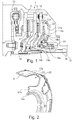
- FIG. 1 A first embodiment of the friction clutch 1 according to the invention (also referred to as a friction clutch) can be seen.
- the friction clutch 1 is designed for a drive train of a motor vehicle, such as a car, truck, bus or agricultural utility vehicle, and serves as a separable torque transmission device for transmitting a torque between an internal combustion engine, such as an Otto or diesel engine and a transmission.
- the friction clutch 1 is designed as a dry-running friction clutch 1, but can alternatively be designed as a wet-running friction clutch 1.
- the friction clutch 1 is also designed and functioning as a double clutch, as is essentially already the case in FIG DE 10 2011 013 475 A1 is known. The disclosure content of the DE 10 2011 013 475 A1 should therefore be considered integrated here.
- the friction clutch 1 has a pressure plate 6, 7 which can be moved back and forth relative to a pressure plate 2, 3 and a clutch disc 4, 5 for engaging and disengaging the clutch 1. Furthermore, the friction clutch 1 also has an actuating element 8, 9 which influences the pressure plate displacement position and is connected to the pressure plate 6, 7 in a rotationally fixed manner, which actuating element 8, 9 has at least one fluid deflection section 10 which, when the clutch 1 is in an operating state, namely when the internal combustion engine is switched on, for cooling the pressure plate 6, 7, the pressure plate 2, 3 and / or the clutch disc 4, 5 introduces a cooling fluid into the interior of the clutch 1.
- the friction clutch 1 is designed as a double clutch
- the friction clutch 2 has independent partial clutches 11 and 12.
- the first partial clutch 11 has a first pressure plate 2, which in turn is rotationally fixed via a torsional vibration damper 13 designed as a dual mass flywheel Crankshaft of the internal combustion engine is non-rotatably connectable, a first clutch disc 4, which in turn can be non-rotatably connected to a first transmission input shaft 14, and a first pressure plate 6, which is displaceable in the axial direction (ie along the clutch axis of rotation 15) of the friction clutch 1.
- the first pressure plate 6 is in turn non-rotatably connected to the first pressure plate 2 and is displaceable in relation to the latter in the axial direction.
- the first clutch disc 4 is also displaceably mounted in the axial direction and can be displaced in the axial direction both with respect to the first pressure plate 6 and with respect to the first pressure plate 2.
- the first pressure plate 6 rests on the first clutch plate 4 and the first pressure plate 2 in such a frictional manner that the first pressure plate 2 is connected to the first clutch plate 4 in a rotationally fixed manner.
- the first pressure plate 6, the first clutch disc 4 and the first pressure plate 2 are in frictional engagement with one another by means of their friction surfaces.
- the first pressure plate 6 presses the first clutch plate 4 in the direction of the first pressure plate 2 in order to produce a rotationally fixed connection of the first clutch plate 4 with the first pressure plate 2.
- the first pressure plate 6 In a disengaged position of the first partial clutch 11, the first pressure plate 6 is in turn arranged at a distance from the first clutch plate 4, whereby the first pressure plate 2 is released from the first clutch plate 4 and therefore no torque between the first pressure plate 2 in this disengaged position and the first clutch disc 4 is transmitted.
- first actuating element 8 is again provided, which first actuating element 8 is designed as a pressure pot and is displaceably mounted in the axial direction, but at the same time is non-rotatably connected to the first pressure plate 6.
- the first actuating element 8 is rigid, that is to say as a rigid and dimensionally stable component, designed / shaped and is not subject to any noticeable elastic deformations during the movement between the engaged and the disengaged position, which lead to the fluid deflection section 10 tilting / rotating or displacing in the radial direction would.
- the second partial clutch 12 of the double clutch is in turn designed and functioning according to the first partial clutch 11.
- the second partial clutch 12 also has a clutch disc 5, hereinafter referred to as the second clutch disc 5, a pressure plate 3, hereinafter referred to as the second pressure plate 3, a pressure plate 7, hereinafter referred to as the second pressure plate 7, and an actuating element 9, hereinafter referred to as the second actuating element 9.
- the second pressure plate 3, like the second pressure plate 7, is connected to the first pressure plate 2 in a rotationally fixed manner.
- the second pressure plate 7 is in turn axially displaceable relative to the second clutch plate 5 and the second pressure plate 3.
- the second clutch disc 5 is again arranged in the axial direction between the second pressure plate 3 and the second pressure plate 7 and is displaceably mounted in the axial direction with respect to the second pressure plate 3 and the second pressure plate 7.
- the displacement position of the second pressure plate 7 is in turn determined by the second actuating element 9, which second actuating element 9 is also designed as a pressure pot.
- the second actuating element 9 presses against the second pressure plate 7 such that the latter is pressed in the direction of the second clutch disc 5 and against the second pressure plate 3.
- the second pressure plate 7 is in frictional engagement with the second clutch plate 5 and the second pressure plate 3 in such a way that the second pressure plate 3 is connected in a rotationally fixed manner to the second clutch plate 5.
- the second pressure plate 7, the second clutch plate 5 and the second pressure plate 3 are in frictional engagement with one another by means of their friction surfaces.
- the second clutch disc 5 can in turn be connected to a second transmission input shaft 16 of a transmission (not shown further here) and is also connected to it in the operating state.
- the second pressure plate 7 In a disengaged position of the second partial clutch 12, the second pressure plate 7 is in turn spaced apart from the second clutch plate 5 and out of frictional contact with the second clutch plate 5, as a result of which the second pressure plate 3 and the second clutch plate 5 are separated.
- the second actuating element 9 is in turn rigid, that is to say as a rigid, dimensionally stable component.
- Both the first actuating element 8 and the second actuating element 9 bear with a radially outer region 17a and 17b on the respective pressure plate 6, 7 in order to actuate / adjust them directly.
- a radially inner region 18a, 18b which is arranged radially further inward than the outer region 17a, 17b with respect to the coupling axis of rotation 15, each of the actuating elements 8 and 9 lies on a corresponding actuating bearing 19a, 19b, which actuating bearing 19a, 19b is in turn displaceable via a slave cylinder 20, namely is displaceable in the axial direction.
- the first actuating element 8 has the at least one fluid deflection section 10 on a wall region 21a which extends essentially in the radial direction and is also provided with the reference numeral 10a below in relation to the first actuating element 8.
- the reference numeral 10a below in relation to the first actuating element 8.
- only one fluid deflection section 10a is configured in the figure, however, several, preferably at least three or at least four fluid deflection sections 10a are arranged on the first actuating element 8, which are arranged at equal distances from one another, distributed along the circumference of the first actuating element 8.
- the fluid deflecting section 10a has a deflecting blade 22, also referred to as a scoop or blade geometry, which is formed in the axial direction by local shaping in the wall region 21a of the first actuating element 8.
- This deflecting blade 22 is shaped by means of a cold forming process.
- the first actuating element 8 is made from a cold-formable metal material, namely a cold-formable steel material.
- the first actuating element 8 is designed as a sheet metal part, which makes it possible to form the first actuating element 8 exclusively by means of forming and punching processes.
- the deflection vane 22 cooperates with an opening 23 to divert / deflect / accelerate a cooling fluid into the interior of the clutch 1.
- the opening 23 is arranged relative to the deflection vane 22 such that when the first actuating element 8 is rotated in a predetermined direction of rotation (in Fig. 1 viewed from the plane of the drawing), during operation of the internal combustion engine, a cooling fluid, which is air here in the case of the dry friction clutch 1, is introduced into the interior of the friction clutch 1 in the axial direction from a side facing away from the first pressure plate 6.
- the opening 23 can in turn preferably be produced by means of a punching process. Deflection blade 22 and opening 23 thus form the fluid deflection section 10a.
- the deflection vane 22 is integral with the wall region 21 and, since this is in turn integral with the rest of the first actuating element 8, is also integral with the first actuating element 8.
- the radially outer region 17a which extends essentially in the axial direction, adjoins a radially outer side of the wall region 21a of the first actuating element 8.
- the radially inner region 18a of the first actuating element 8 adjoins a radially inner side of the wall region 21a of the first actuating element 8.
- the second actuating element 9 is in turn designed in accordance with the first actuating element 8. The aforementioned statements thus also apply to the second actuating element 9.
- the second actuating element 9 differs from the first actuating element 8 only with regard to the geometric configuration of the wall region 21b, the radially outer region 17b and the radially inner region 18b.
- the second actuator 9 is again a pressure pot, i.e. designed essentially pot-shaped.
- the wall region 21b of the second actuating element 9 extends essentially obliquely outwards in the radial direction, the radially outer region 17b being offset in the axial direction, relative to the radially inner region 18b, towards the wall region 21a of the first actuating element 8.
- the second actuating element 9 also has a fluid deflection section 10, which is subsequently also provided with the reference symbol 10b with respect to the second actuating element 9.
- the fluid deflecting section 10b of the second actuating element 9 is configured like the previously described fluid deflecting section 10a of the first actuating element 8.
- the second actuating element 9 also has a plurality of, preferably at least three or at least four, fluid deflection sections 10b arranged uniformly distributed along the circumference.
- the first actuating element 8 is arranged relative to the second actuating element 9 such that the radially outer region 17a of the first actuating element 8 extends around the second actuating element 9 in the radial direction.
- a center point of the fluid deflection section 10a of the first actuating element 8, seen in the radial direction, is also arranged in the radial direction outside a center point of the fluid deflection section 10b of the second actuation element 9.
- a groove geometry is integrated in at least one of the pressure plates 6, 7.
- Such a groove geometry is preferably formed from at least one groove 24 which extends essentially in the radial direction.
- such a groove geometry can also be configured in the first pressure plate 6 and / or in the first pressure plate 2 and / or in the second pressure plate 3.
- a groove geometry can also be integrated in the first clutch disc and / or in the second clutch disc 5.
- Such a groove geometry has a groove 24 configured in this way, which is open to the surroundings, particularly in the engaged position of the respective partial coupling 11, 12, on both a radially inner side and on a radially outer side, as a result of which the cooling fluid also in the engaged position, that is, with friction surfaces between the plates 2, 3, 6, 7 on the clutch disks 4, 5, cooling fluid can flow through and thereby actively cool the components.
- the fluid flow / cooling fluid flow made possible by the groove geometry is in Fig. 3 marked with the flow arrows 25.
- the two pressure plates 2, 3 and the two pressure plates 6, 7 are also all or partially / occasionally made of a formable / cold-formable metal (steel or aluminum alloy), which makes the groove geometry particularly easy to produce.
- blade geometries 22 are integrated in pressure pots 8, 9 with the present invention. This can be easily represented since these components, which are produced by stamping and shaping, have openings 23 from the outset. Ultimately, the otherwise punched-out area is left and is only designed to be aerodynamically efficient.
- the fan geometries are components of rigid actuating elements 8, 9 (pressure pots), compared to the prior art, has the advantage that they can be represented relatively easily since in contrast to that, the base material does not have to be heat-treated with a disc spring and can be optimized for the requirements for forming processes.
- fan geometries are arranged in rigid elements (in contrast to swung-out plate spring tongues according to the prior art), for constant cross-sectional conditions or their constant flow and thus reproducible flows.
- both or only one pressure pot 8, 9 can be provided with blades 22 (of the fluid deflection sections 10a, 10b).
- a blade geometry 22 makes particular sense in the case of the outer pressure pot (first actuating element 8), which is in direct contact with the standing outside air. Suitable ventilation of the bell bottom with radially extending ribs can be increased.
- the arrangement of blades 22 in pressure pots 8, 9 is particularly advantageously combined with grooves 24 in the thermal masses in the area of the friction contact / the friction surfaces.
- the groove geometry ensures a permanent flow through the friction area, especially when the partial clutches 11, 12 are closed.
- This groove geometry can be represented particularly advantageously in the case of thermally produced sheet metal thermal masses, since there is no additional machining effort in comparison to casting masses.
Landscapes
- Engineering & Computer Science (AREA)
- General Engineering & Computer Science (AREA)
- Mechanical Engineering (AREA)
- Mechanical Operated Clutches (AREA)
- General Details Of Gearings (AREA)
Claims (8)
- Embrayage à friction (1) pour une chaîne cinématique d'un véhicule, comprenant un plateau d'appui (6, 7) qui peut se déplacer en translation par rapport à un plateau de pression (2, 3) et à un disque d'embrayage (4, 5) pour embrayer et débrayer l'embrayage (1) et un élément d'actionnement (8, 9) qui agit sur la position de translation du plateau d'appui et qui est relié solidairement en rotation au plateau d'appui (6, 7), lequel élément d'actionnement (8, 9) présente au moins une partie de déviation de fluide (10) qui, dans un état de fonctionnement de l'embrayage (1), introduit un fluide de refroidissement dans l'espace intérieur de l'embrayage (1) afin de refroidir le plateau d'appui (6, 7), le plateau de pression (2, 3) et/ou le disque d'embrayage (4, 5) et l'élément d'actionnement (8, 9) étant conçu comme un composant rigide, caractérisé en ce qu'au moins le plateau de pression (2, 3) ou le plateau d'appui (6, 7) présente au moins une deuxième partie de déviation de fluide qui redirige le fluide de refroidissement et/ou présente, dans la région d'une surface de friction reliée au disque d'embrayage (4, 5) en position engagée, une géométrie de rainure (24) qui est conçue pour distribuer le fluide de refroidissement.
- Embrayage à friction (1) selon la revendication 1, caractérisé en ce que l'élément d'actionnement (8, 9) est conçu comme un pot de pression.
- Embrayage à friction (1) selon la revendication 1 ou 2, caractérisé en ce que l'élément d'actionnement (8, 9) est réalisé en un matériau métallique formable à froid.
- Embrayage à friction (1) selon la revendication 3, caractérisé en ce que l'élément d'actionnement (8, 9) est conçu comme une pièce en tôle à partir du matériau métallique.
- Embrayage à friction (1) selon l'une quelconque des revendications 1 à 4, caractérisé en ce que la ou les parties de déviation de fluide (10) présentent un déflecteur (22) conçu solidaire de l'élément d'actionnement (8, 9), le déflecteur (22) étant réalisé par un processus de formage, de préférence un processus de formage à froid et/ou un processus de poinçonnage.
- Embrayage à friction (1) selon l'une quelconque des revendications 1 à 5, caractérisé en ce que l'embrayage à friction (1) est conçu comme un double embrayage présentant deux embrayages partiels (11, 12), un élément d'actionnement (8, 9) étant prévu pour chaque embrayage partiel (11, 12).
- Embrayage à friction (1) pour une chaîne cinématique d'un véhicule, comprenant un plateau d'appui (6, 7) qui peut se déplacer en translation par rapport à un plateau de pression (2, 3) et à un disque d'embrayage (4, 5) pour embrayer et débrayer l'embrayage (1) et un élément d'actionnement (8, 9) qui agit sur la position de translation du plateau d'appui et qui est relié solidairement en rotation au plateau d'appui (6, 7), lequel élément d'actionnement (8, 9) présente au moins une partie de déviation de fluide (10) qui, dans un état de fonctionnement de l'embrayage (1), introduit un fluide de refroidissement dans l'espace intérieur de l'embrayage (1) afin de refroidir le plateau d'appui (6, 7), le plateau de pression (2, 3) et/ou le disque d'embrayage (4, 5) et l'élément d'actionnement (8, 9) étant conçu comme un composant rigide, caractérisé en ce qu'un premier élément d'actionnement (8) d'un premier embrayage partiel (11) et un deuxième élément d'actionnement (9) d'un deuxième embrayage partiel (12) ont chacun au moins une partie de déviation de fluide (10a, 10b), le premier élément d'actionnement (8) s'étendant au moins partiellement radialement à l'extérieur du deuxième élément d'actionnement (9).
- Système d'embrayage à friction (1) et cloche de boîte de vitesses, l'embrayage à friction (1) étant configuré selon le préambule de la revendication 1 et la cloche de boîte de vitesses, disposée à côté de l'embrayage à friction (1), étant constituée d'une pluralité de nervures d'entraînement et/ou de déviation du fluide de refroidissement.
Applications Claiming Priority (2)
| Application Number | Priority Date | Filing Date | Title |
|---|---|---|---|
| DE102014206490 | 2014-04-04 | ||
| PCT/DE2015/200170 WO2015149785A1 (fr) | 2014-04-04 | 2015-03-19 | Embrayage à actionnement direct et à géométrie de ventilation |
Publications (2)
| Publication Number | Publication Date |
|---|---|
| EP3126693A1 EP3126693A1 (fr) | 2017-02-08 |
| EP3126693B1 true EP3126693B1 (fr) | 2020-02-26 |
Family
ID=53040330
Family Applications (1)
| Application Number | Title | Priority Date | Filing Date |
|---|---|---|---|
| EP15720197.1A Active EP3126693B1 (fr) | 2014-04-04 | 2015-03-19 | Embrayage à actionnement direct et à géométrie de ventilation |
Country Status (6)
| Country | Link |
|---|---|
| US (1) | US20170030418A1 (fr) |
| EP (1) | EP3126693B1 (fr) |
| JP (1) | JP2017511453A (fr) |
| CN (1) | CN106133363B (fr) |
| DE (1) | DE112015001611A5 (fr) |
| WO (1) | WO2015149785A1 (fr) |
Families Citing this family (5)
| Publication number | Priority date | Publication date | Assignee | Title |
|---|---|---|---|---|
| DE102017130266A1 (de) * | 2017-07-17 | 2019-01-17 | Schaeffler Technologies AG & Co. KG | Hybridmodul |
| DE102017129513A1 (de) | 2017-12-12 | 2019-06-13 | Schaeffler Technologies AG & Co. KG | Reibungskupplung mit Kühlkanal |
| DE102018009087A1 (de) * | 2018-11-17 | 2020-05-20 | Borgwarner Inc. | Doppelkupplung |
| DE102019123096A1 (de) * | 2019-08-02 | 2021-02-04 | Schaeffler Technologies AG & Co. KG | Kupplungssystem |
| WO2022064635A1 (fr) | 2020-09-25 | 2022-03-31 | 有限会社T.P.P. | Dispositif de plateau d'embrayage pour un embrayage à friction |
Family Cites Families (17)
| Publication number | Priority date | Publication date | Assignee | Title |
|---|---|---|---|---|
| US1742804A (en) * | 1926-01-05 | 1930-01-07 | Brown Lipe Gear Co | Friction clutch |
| DE1294228C2 (de) | 1963-10-26 | 1977-03-10 | LuK Lamellen und Kupplungsbau GmbH, 7580 Bühl | Doppelreibungskupplung fuer schlepper, geraetetraeger und aehnliche fahrzeuge |
| JPS5597224U (fr) * | 1978-12-27 | 1980-07-05 | ||
| DE3304670C2 (de) | 1983-02-11 | 1995-02-02 | Luk Lamellen & Kupplungsbau | Tellerfeder, sowie mit einer solchen ausgerüstete Reibungskupplung |
| FR2546595B1 (fr) * | 1983-05-24 | 1988-12-30 | Valeo | Mecanisme d'embrayage et plateau de pression pour un tel mecanisme d'embrayage, notamment pour vehicule automobile |
| JPS60143936U (ja) * | 1984-03-06 | 1985-09-24 | 株式会社 大金製作所 | クラツチの冷却装置 |
| JPH0430429Y2 (fr) * | 1985-08-02 | 1992-07-22 | ||
| DE3602716C2 (de) * | 1986-01-30 | 1998-11-19 | Luk Lamellen & Kupplungsbau | Reibungskupplung |
| JPH03121229U (fr) * | 1990-03-26 | 1991-12-12 | ||
| JPH10184800A (ja) * | 1996-12-25 | 1998-07-14 | Exedy Corp | フライホイール |
| DE10110897B4 (de) * | 2000-03-22 | 2013-09-12 | Schaeffler Technologies AG & Co. KG | Kupplung, insbesondere für den Antriebsstrang eines Kraftfahrzeugs |
| DE10148428A1 (de) * | 2001-10-01 | 2003-04-17 | Zf Sachs Ag | Gehäuseanordnung für eine Reibungskupplung |
| DE10338558A1 (de) | 2002-08-23 | 2004-03-04 | Luk Lamellen Und Kupplungsbau Beteiligungs Kg | Verfahren, Vorrichtung und deren Verwendung zum Betrieb eines Kraftfahrzeuges |
| EP1783388B1 (fr) * | 2005-11-04 | 2014-07-02 | Schaeffler Technologies GmbH & Co. KG | Dispositif d'embrayage à disques multiples |
| WO2010006579A1 (fr) * | 2008-07-14 | 2010-01-21 | Luk Lamellen Und Kupplungsbau Beteiligungs Kg | Embrayage double |
| DE112011101030A5 (de) | 2010-03-25 | 2013-01-17 | Schaeffler Technologies AG & Co. KG | Doppelkupplung |
| DE102011017380A1 (de) * | 2010-05-06 | 2011-11-10 | Schaeffler Technologies Gmbh & Co. Kg | Doppelkupplung |
-
2015
- 2015-03-19 EP EP15720197.1A patent/EP3126693B1/fr active Active
- 2015-03-19 US US15/301,744 patent/US20170030418A1/en not_active Abandoned
- 2015-03-19 WO PCT/DE2015/200170 patent/WO2015149785A1/fr not_active Ceased
- 2015-03-19 JP JP2017503049A patent/JP2017511453A/ja active Pending
- 2015-03-19 CN CN201580017741.3A patent/CN106133363B/zh active Active
- 2015-03-19 DE DE112015001611.2T patent/DE112015001611A5/de not_active Withdrawn
Non-Patent Citations (1)
| Title |
|---|
| None * |
Also Published As
| Publication number | Publication date |
|---|---|
| CN106133363B (zh) | 2018-11-06 |
| US20170030418A1 (en) | 2017-02-02 |
| DE112015001611A5 (de) | 2016-12-29 |
| CN106133363A (zh) | 2016-11-16 |
| JP2017511453A (ja) | 2017-04-20 |
| WO2015149785A1 (fr) | 2015-10-08 |
| EP3126693A1 (fr) | 2017-02-08 |
Similar Documents
| Publication | Publication Date | Title |
|---|---|---|
| EP3126693B1 (fr) | Embrayage à actionnement direct et à géométrie de ventilation | |
| EP2387673B2 (fr) | Ensemble embrayage | |
| EP2732174B1 (fr) | Double embrayage | |
| EP4150227B1 (fr) | Ensemble d'embrayage multidisques ayant des unités de plaque de ressort à action indépendante pour relier deux disques de composant à un arbre de sortie | |
| DE102014200854A1 (de) | Reibschaltelement für ein Getriebe eines Fahrzeuges | |
| WO2007112722A1 (fr) | chambre radiale d'écoulement pour accouplements dans un module d'accouplement | |
| DE102013213983A1 (de) | Doppelkupplung | |
| EP2890912B2 (fr) | Plateau de pression segmenté pour embrayage à friction, et embrayage à friction et véhicule à moteur correspondants | |
| EP3529096B1 (fr) | Module hybride et chaîne cinématique | |
| DE102011086712A1 (de) | Drehmomentübertragungseinrichtung | |
| DE102015212662A1 (de) | Reibschaltelement für ein Getriebe eines Fahrzeuges | |
| DE102014203416A1 (de) | Reibungskupplung | |
| WO2019120366A1 (fr) | Unité de transmission de couple et chaîne cinématique | |
| DE60320467T2 (de) | Reibscheibe einer reibungskupplung und kupplung mit einer solchen scheibe | |
| DE10102828B4 (de) | Reibungskupplung mit einer Gegenanpressplatte, die einen Läufer einer rotierenden elektrischen Maschine trägt, insbesondere für Kraftfahrzeuge | |
| DE102016217590A1 (de) | Elektrische Achsenanordnung mit innengekühlten Reibelementen | |
| DE102014209973A1 (de) | Rotationsbauteil, Verfahren zum Herstellen eines Rotationsbauteils, Lamellenträger sowie Drehmomentübertragungseinrichtung | |
| EP1647729A2 (fr) | Dispositif d'embrayages pour embrayages multiples | |
| WO2018091022A1 (fr) | Dispositif de transmission de couple | |
| DE102013214503A1 (de) | Gehäusedeckel mit seitlich ausgestellter Kühleinrichtung | |
| DE102020212758A1 (de) | Kupplung, insbesondere Doppelkupplung für ein Kraftfahrzeug | |
| EP3085984A1 (fr) | Combinaison de freinage pour embrayage | |
| DE102014204865A1 (de) | Rotationsbauteil, Verzahnung zweier Rotationsbauteile sowie Verfahren zum Herstellen eines Rotationsbauteils | |
| DE102014208097A1 (de) | Reibungskupplungseinrichtung | |
| EP2927526B1 (fr) | Aération côté moteur à combustion interne par des ouvertures de refroidissement dans l'amortisseur |
Legal Events
| Date | Code | Title | Description |
|---|---|---|---|
| STAA | Information on the status of an ep patent application or granted ep patent |
Free format text: STATUS: THE INTERNATIONAL PUBLICATION HAS BEEN MADE |
|
| PUAI | Public reference made under article 153(3) epc to a published international application that has entered the european phase |
Free format text: ORIGINAL CODE: 0009012 |
|
| STAA | Information on the status of an ep patent application or granted ep patent |
Free format text: STATUS: REQUEST FOR EXAMINATION WAS MADE |
|
| 17P | Request for examination filed |
Effective date: 20161104 |
|
| AK | Designated contracting states |
Kind code of ref document: A1 Designated state(s): AL AT BE BG CH CY CZ DE DK EE ES FI FR GB GR HR HU IE IS IT LI LT LU LV MC MK MT NL NO PL PT RO RS SE SI SK SM TR |
|
| AX | Request for extension of the european patent |
Extension state: BA ME |
|
| RIN1 | Information on inventor provided before grant (corrected) |
Inventor name: HELLGOTH, RENE Inventor name: DAIKELER, RENE |
|
| DAV | Request for validation of the european patent (deleted) | ||
| DAX | Request for extension of the european patent (deleted) | ||
| GRAP | Despatch of communication of intention to grant a patent |
Free format text: ORIGINAL CODE: EPIDOSNIGR1 |
|
| STAA | Information on the status of an ep patent application or granted ep patent |
Free format text: STATUS: GRANT OF PATENT IS INTENDED |
|
| INTG | Intention to grant announced |
Effective date: 20191120 |
|
| GRAS | Grant fee paid |
Free format text: ORIGINAL CODE: EPIDOSNIGR3 |
|
| GRAA | (expected) grant |
Free format text: ORIGINAL CODE: 0009210 |
|
| STAA | Information on the status of an ep patent application or granted ep patent |
Free format text: STATUS: THE PATENT HAS BEEN GRANTED |
|
| AK | Designated contracting states |
Kind code of ref document: B1 Designated state(s): AL AT BE BG CH CY CZ DE DK EE ES FI FR GB GR HR HU IE IS IT LI LT LU LV MC MK MT NL NO PL PT RO RS SE SI SK SM TR |
|
| REG | Reference to a national code |
Ref country code: GB Ref legal event code: FG4D Free format text: NOT ENGLISH |
|
| REG | Reference to a national code |
Ref country code: CH Ref legal event code: EP |
|
| REG | Reference to a national code |
Ref country code: AT Ref legal event code: REF Ref document number: 1237984 Country of ref document: AT Kind code of ref document: T Effective date: 20200315 |
|
| REG | Reference to a national code |
Ref country code: IE Ref legal event code: FG4D Free format text: LANGUAGE OF EP DOCUMENT: GERMAN |
|
| REG | Reference to a national code |
Ref country code: DE Ref legal event code: R096 Ref document number: 502015011856 Country of ref document: DE |
|
| PG25 | Lapsed in a contracting state [announced via postgrant information from national office to epo] |
Ref country code: FI Free format text: LAPSE BECAUSE OF FAILURE TO SUBMIT A TRANSLATION OF THE DESCRIPTION OR TO PAY THE FEE WITHIN THE PRESCRIBED TIME-LIMIT Effective date: 20200226 Ref country code: NO Free format text: LAPSE BECAUSE OF FAILURE TO SUBMIT A TRANSLATION OF THE DESCRIPTION OR TO PAY THE FEE WITHIN THE PRESCRIBED TIME-LIMIT Effective date: 20200526 Ref country code: RS Free format text: LAPSE BECAUSE OF FAILURE TO SUBMIT A TRANSLATION OF THE DESCRIPTION OR TO PAY THE FEE WITHIN THE PRESCRIBED TIME-LIMIT Effective date: 20200226 |
|
| REG | Reference to a national code |
Ref country code: NL Ref legal event code: MP Effective date: 20200226 |
|
| REG | Reference to a national code |
Ref country code: LT Ref legal event code: MG4D |
|
| PG25 | Lapsed in a contracting state [announced via postgrant information from national office to epo] |
Ref country code: SE Free format text: LAPSE BECAUSE OF FAILURE TO SUBMIT A TRANSLATION OF THE DESCRIPTION OR TO PAY THE FEE WITHIN THE PRESCRIBED TIME-LIMIT Effective date: 20200226 Ref country code: LV Free format text: LAPSE BECAUSE OF FAILURE TO SUBMIT A TRANSLATION OF THE DESCRIPTION OR TO PAY THE FEE WITHIN THE PRESCRIBED TIME-LIMIT Effective date: 20200226 Ref country code: HR Free format text: LAPSE BECAUSE OF FAILURE TO SUBMIT A TRANSLATION OF THE DESCRIPTION OR TO PAY THE FEE WITHIN THE PRESCRIBED TIME-LIMIT Effective date: 20200226 Ref country code: GR Free format text: LAPSE BECAUSE OF FAILURE TO SUBMIT A TRANSLATION OF THE DESCRIPTION OR TO PAY THE FEE WITHIN THE PRESCRIBED TIME-LIMIT Effective date: 20200527 Ref country code: IS Free format text: LAPSE BECAUSE OF FAILURE TO SUBMIT A TRANSLATION OF THE DESCRIPTION OR TO PAY THE FEE WITHIN THE PRESCRIBED TIME-LIMIT Effective date: 20200626 Ref country code: BG Free format text: LAPSE BECAUSE OF FAILURE TO SUBMIT A TRANSLATION OF THE DESCRIPTION OR TO PAY THE FEE WITHIN THE PRESCRIBED TIME-LIMIT Effective date: 20200526 |
|
| PG25 | Lapsed in a contracting state [announced via postgrant information from national office to epo] |
Ref country code: NL Free format text: LAPSE BECAUSE OF FAILURE TO SUBMIT A TRANSLATION OF THE DESCRIPTION OR TO PAY THE FEE WITHIN THE PRESCRIBED TIME-LIMIT Effective date: 20200226 |
|
| PG25 | Lapsed in a contracting state [announced via postgrant information from national office to epo] |
Ref country code: SM Free format text: LAPSE BECAUSE OF FAILURE TO SUBMIT A TRANSLATION OF THE DESCRIPTION OR TO PAY THE FEE WITHIN THE PRESCRIBED TIME-LIMIT Effective date: 20200226 Ref country code: LT Free format text: LAPSE BECAUSE OF FAILURE TO SUBMIT A TRANSLATION OF THE DESCRIPTION OR TO PAY THE FEE WITHIN THE PRESCRIBED TIME-LIMIT Effective date: 20200226 Ref country code: EE Free format text: LAPSE BECAUSE OF FAILURE TO SUBMIT A TRANSLATION OF THE DESCRIPTION OR TO PAY THE FEE WITHIN THE PRESCRIBED TIME-LIMIT Effective date: 20200226 Ref country code: PT Free format text: LAPSE BECAUSE OF FAILURE TO SUBMIT A TRANSLATION OF THE DESCRIPTION OR TO PAY THE FEE WITHIN THE PRESCRIBED TIME-LIMIT Effective date: 20200719 Ref country code: CZ Free format text: LAPSE BECAUSE OF FAILURE TO SUBMIT A TRANSLATION OF THE DESCRIPTION OR TO PAY THE FEE WITHIN THE PRESCRIBED TIME-LIMIT Effective date: 20200226 Ref country code: RO Free format text: LAPSE BECAUSE OF FAILURE TO SUBMIT A TRANSLATION OF THE DESCRIPTION OR TO PAY THE FEE WITHIN THE PRESCRIBED TIME-LIMIT Effective date: 20200226 Ref country code: ES Free format text: LAPSE BECAUSE OF FAILURE TO SUBMIT A TRANSLATION OF THE DESCRIPTION OR TO PAY THE FEE WITHIN THE PRESCRIBED TIME-LIMIT Effective date: 20200226 Ref country code: DK Free format text: LAPSE BECAUSE OF FAILURE TO SUBMIT A TRANSLATION OF THE DESCRIPTION OR TO PAY THE FEE WITHIN THE PRESCRIBED TIME-LIMIT Effective date: 20200226 Ref country code: SK Free format text: LAPSE BECAUSE OF FAILURE TO SUBMIT A TRANSLATION OF THE DESCRIPTION OR TO PAY THE FEE WITHIN THE PRESCRIBED TIME-LIMIT Effective date: 20200226 |
|
| REG | Reference to a national code |
Ref country code: CH Ref legal event code: PL |
|
| REG | Reference to a national code |
Ref country code: DE Ref legal event code: R097 Ref document number: 502015011856 Country of ref document: DE |
|
| PG25 | Lapsed in a contracting state [announced via postgrant information from national office to epo] |
Ref country code: MC Free format text: LAPSE BECAUSE OF FAILURE TO SUBMIT A TRANSLATION OF THE DESCRIPTION OR TO PAY THE FEE WITHIN THE PRESCRIBED TIME-LIMIT Effective date: 20200226 |
|
| REG | Reference to a national code |
Ref country code: BE Ref legal event code: MM Effective date: 20200331 |
|
| PG25 | Lapsed in a contracting state [announced via postgrant information from national office to epo] |
Ref country code: LU Free format text: LAPSE BECAUSE OF NON-PAYMENT OF DUE FEES Effective date: 20200319 |
|
| PLBE | No opposition filed within time limit |
Free format text: ORIGINAL CODE: 0009261 |
|
| STAA | Information on the status of an ep patent application or granted ep patent |
Free format text: STATUS: NO OPPOSITION FILED WITHIN TIME LIMIT |
|
| PG25 | Lapsed in a contracting state [announced via postgrant information from national office to epo] |
Ref country code: IE Free format text: LAPSE BECAUSE OF NON-PAYMENT OF DUE FEES Effective date: 20200319 Ref country code: CH Free format text: LAPSE BECAUSE OF NON-PAYMENT OF DUE FEES Effective date: 20200331 Ref country code: LI Free format text: LAPSE BECAUSE OF NON-PAYMENT OF DUE FEES Effective date: 20200331 Ref country code: IT Free format text: LAPSE BECAUSE OF FAILURE TO SUBMIT A TRANSLATION OF THE DESCRIPTION OR TO PAY THE FEE WITHIN THE PRESCRIBED TIME-LIMIT Effective date: 20200226 |
|
| 26N | No opposition filed |
Effective date: 20201127 |
|
| PG25 | Lapsed in a contracting state [announced via postgrant information from national office to epo] |
Ref country code: BE Free format text: LAPSE BECAUSE OF NON-PAYMENT OF DUE FEES Effective date: 20200331 Ref country code: PL Free format text: LAPSE BECAUSE OF FAILURE TO SUBMIT A TRANSLATION OF THE DESCRIPTION OR TO PAY THE FEE WITHIN THE PRESCRIBED TIME-LIMIT Effective date: 20200226 Ref country code: SI Free format text: LAPSE BECAUSE OF FAILURE TO SUBMIT A TRANSLATION OF THE DESCRIPTION OR TO PAY THE FEE WITHIN THE PRESCRIBED TIME-LIMIT Effective date: 20200226 |
|
| GBPC | Gb: european patent ceased through non-payment of renewal fee |
Effective date: 20200526 |
|
| PG25 | Lapsed in a contracting state [announced via postgrant information from national office to epo] |
Ref country code: GB Free format text: LAPSE BECAUSE OF NON-PAYMENT OF DUE FEES Effective date: 20200526 |
|
| REG | Reference to a national code |
Ref country code: AT Ref legal event code: MM01 Ref document number: 1237984 Country of ref document: AT Kind code of ref document: T Effective date: 20200319 |
|
| PG25 | Lapsed in a contracting state [announced via postgrant information from national office to epo] |
Ref country code: AT Free format text: LAPSE BECAUSE OF NON-PAYMENT OF DUE FEES Effective date: 20200319 |
|
| PG25 | Lapsed in a contracting state [announced via postgrant information from national office to epo] |
Ref country code: TR Free format text: LAPSE BECAUSE OF FAILURE TO SUBMIT A TRANSLATION OF THE DESCRIPTION OR TO PAY THE FEE WITHIN THE PRESCRIBED TIME-LIMIT Effective date: 20200226 Ref country code: MT Free format text: LAPSE BECAUSE OF FAILURE TO SUBMIT A TRANSLATION OF THE DESCRIPTION OR TO PAY THE FEE WITHIN THE PRESCRIBED TIME-LIMIT Effective date: 20200226 Ref country code: CY Free format text: LAPSE BECAUSE OF FAILURE TO SUBMIT A TRANSLATION OF THE DESCRIPTION OR TO PAY THE FEE WITHIN THE PRESCRIBED TIME-LIMIT Effective date: 20200226 |
|
| PG25 | Lapsed in a contracting state [announced via postgrant information from national office to epo] |
Ref country code: MK Free format text: LAPSE BECAUSE OF FAILURE TO SUBMIT A TRANSLATION OF THE DESCRIPTION OR TO PAY THE FEE WITHIN THE PRESCRIBED TIME-LIMIT Effective date: 20200226 Ref country code: AL Free format text: LAPSE BECAUSE OF FAILURE TO SUBMIT A TRANSLATION OF THE DESCRIPTION OR TO PAY THE FEE WITHIN THE PRESCRIBED TIME-LIMIT Effective date: 20200226 |
|
| P01 | Opt-out of the competence of the unified patent court (upc) registered |
Effective date: 20230522 |
|
| PGFP | Annual fee paid to national office [announced via postgrant information from national office to epo] |
Ref country code: FR Payment date: 20250325 Year of fee payment: 11 |
|
| PGFP | Annual fee paid to national office [announced via postgrant information from national office to epo] |
Ref country code: DE Payment date: 20250521 Year of fee payment: 11 |