EP3126849B1 - Aktuatormodul zum ansteuern einer last - Google Patents
Aktuatormodul zum ansteuern einer last Download PDFInfo
- Publication number
- EP3126849B1 EP3126849B1 EP15719859.9A EP15719859A EP3126849B1 EP 3126849 B1 EP3126849 B1 EP 3126849B1 EP 15719859 A EP15719859 A EP 15719859A EP 3126849 B1 EP3126849 B1 EP 3126849B1
- Authority
- EP
- European Patent Office
- Prior art keywords
- frame
- deformable frame
- actuator
- nodal points
- static
- Prior art date
- Legal status (The legal status is an assumption and is not a legal conclusion. Google has not performed a legal analysis and makes no representation as to the accuracy of the status listed.)
- Active
Links
Images





Classifications
-
- G—PHYSICS
- G01—MEASURING; TESTING
- G01Q—SCANNING-PROBE TECHNIQUES OR APPARATUS; APPLICATIONS OF SCANNING-PROBE TECHNIQUES, e.g. SCANNING PROBE MICROSCOPY [SPM]
- G01Q10/00—Scanning or positioning arrangements, i.e. arrangements for actively controlling the movement or position of the probe
- G01Q10/04—Fine scanning or positioning
-
- G—PHYSICS
- G06—COMPUTING OR CALCULATING; COUNTING
- G06F—ELECTRIC DIGITAL DATA PROCESSING
- G06F30/00—Computer-aided design [CAD]
- G06F30/20—Design optimisation, verification or simulation
-
- G—PHYSICS
- G01—MEASURING; TESTING
- G01Q—SCANNING-PROBE TECHNIQUES OR APPARATUS; APPLICATIONS OF SCANNING-PROBE TECHNIQUES, e.g. SCANNING PROBE MICROSCOPY [SPM]
- G01Q30/00—Auxiliary means serving to assist or improve the scanning probe techniques or apparatus, e.g. display or data processing devices
- G01Q30/04—Display or data processing devices
-
- G—PHYSICS
- G06—COMPUTING OR CALCULATING; COUNTING
- G06F—ELECTRIC DIGITAL DATA PROCESSING
- G06F17/00—Digital computing or data processing equipment or methods, specially adapted for specific functions
- G06F17/10—Complex mathematical operations
- G06F17/11—Complex mathematical operations for solving equations, e.g. nonlinear equations, general mathematical optimization problems
Definitions
- the present disclosure relates to an actuator module, actuator system comprising the actuator module, e.g. for use in an atomic force microscopy (AFM) system.
- the disclosure further relates to a computer-implemented method for designing an actuator module, a computer-readable storage medium, and a method for manufacturing an actuator module.
- An actuator module can be used to actuate a load, e.g. cause a vibrational motion of the load.
- a load e.g. cause a vibrational motion of the load.
- an actuator module can be used as a scan head that actuates a probe tip for scanning a specimen surface.
- the dynamic transfer function or frequency response function between an applied actuator force (input) and a displacement of an actuating surface or probe (output) be as smooth as possible, e.g. free of disturbing resonances.
- movements of the actuator module may excite base frame vibrations . These induced vibrations may influence the transfer or response function and deteriorate performance of the actuator system.
- an actuator module connectable to a base frame wherein a transfer of vibrations from the actuator module to the base frame is reduced.
- EP 2 242 123 A2 , EP 0 643 427 A1 , EP 0 741 421 A2 , US 7,117,724 B1 describe actuator modules comprising a deformable frame.
- a first aspect of the present disclosure provides an actuator module for actuating a load according to claim 1.
- the actuator module comprises a deformable frame and an actuator connected to the deformable frame.
- the deformable frame has a stiffness distribution and mass distribution determining vibrational eigenmodes of the deformable frame.
- An interface of the deformable frame comprises a plurality of mode nodal points defined as points that are stationary during modal deformation of the deformable frame in an excited state of one of the eigenmodes.
- the actuator is connected to the deformable frame and arranged for exerting a time-varying force distribution onto the deformable frame via a connection between the deformable frame and the actuator.
- the interface of the deformable frame comprises a plurality of static nodal points defined as points that are stationary during static deformation of the deformable frame when the force distribution exerted by the actuator is applied under static or quasi-static conditions.
- the time-varying force distribution couples to the excited state of the eigenmode.
- the deformable frame comprises an actuation surface, in use, oscillating due to the combined modal and static deformations of the deformable frame for actuating the load contacting and/or connected to said actuation surface.
- the force distribution, stiffness distribution, and mass distribution are adapted to have the static nodal points coincide with the mode nodal points or at least be as close together as feasible.
- a deformable frame has vibrational eigenmodes depending on a stiffness distribution and mass distribution of the deformable frame.
- a time-varying force distribution is arranged to couple to an excited state of one of the eigenmodes, e.g. near the associated eigenfrequency and along a similar direction of deformation as the eigenmode, the deformable frame can start to resonate in the said eigenmode.
- This is referred to as the modal deformation of the frame and may be regarded as the deformation that could take place even if the external force is removed.
- (pure) modal deformation i.e.
- 'mode nodal points' e.g. points on a respective nodal line through the frame
- these mode nodal points do not displace with respect to a centre of mass of the deformable frame under the influence of modal deformation.
- the frame deforms depending on a stiffness distribution of the frame and a distribution of the force onto the frame. When the force is applied under static or quasi-static conditions, this is referred to as the 'static deformation' of the frame.
- static nodal points' certain points of the frame, referred here as the 'static nodal points', remain stationary when a magnitude of the static force is varied slowly.
- these static nodal points do not displace with respect to a centre of mass of the deformable frame during quasi-static variation of the exerted force.
- Static or quasi static conditions are obtained at frequencies well below the lowest eigenfrequency of the frame, i.e. when the influence of modal deformation can be neglected.
- static nodal points can be observed as those points that remain in the same place when a static force is applied compared to when no force is applied.
- nodal points exhibit minimal or no displacement, they provide an advantageous location for connecting the actuator module to the base frame. Since there will be minimal or no relative translation at these points, vibrational transfer via said point can be minimal.
- a position of the nodal points may vary depending on a frequency of the actuating force. Accordingly, a connection to a specific point of the frame that is stationary at one frequency, may not be stationary at another frequency. This behaviour is found to be caused by the fact that in a conventional actuator module, the mode nodal points and static nodal points do not coincide. Therefore, in a conventional actuator module a position of the effective nodal points (i.e. points that remain stationary) can depend on the relative contributions of the static and modal deformations which contributions in turn may depend on the frequency of the actuator force.
- a frequency dependence of a position of the nodal points is reduced.
- a position of the static nodal points can be adapted by a choice of the force distribution of the actuator on the frame and/or the stiffness distribution of the frame.
- a position of the mode nodal points can be adapted by a choice of the mass distribution of the frame and/or the stiffness distribution of the frame. Accordingly, one or more of the force distribution, stiffness distribution, and mass distribution can be adapted to have the static nodal points coincide with the mode nodal points.
- the static nodal points must coincide with the mode nodal points as close together as possible across a dimension, i.e. within a tolerance or distance of less than one percent of a maximum size dimension (e.g. length or width or largest cross-section diameter) of the interface or surface of the deformable frame where the connectors to the base frame are to be applied, preferably even closer, e.g. less than half a percent, more preferably less than a tenth of a percent, most preferably fully coinciding at least within a measurable margin of error.
- the connectors centred at the respective static nodal points with the corresponding mode nodal points nearby e.g. within one percent of the frame size
- the actuator module can be more easily connected to a base frame.
- vibrations in the module caused by the actuator may have minimal influence on the frame connectors, e.g. the forces on the frame connectors as a result of the combined static and modal transformations may be minimal.
- a frame connector comprises a respective recess and/or protrusion centred on the coinciding nodal points. In this way the position of the nodal points can be easily identified and the deformable frame can be held via the recess and/or protrusion, e.g.
- connection points between the actuator module and base frame By providing connections between the actuator module and base frame that are rotationally free around respective coinciding nodal points, twisting of the frame around said points that may occur during modal and/or static deformation is not passed to the base frame.
- the position By providing at least three connection points between the actuator module and base frame, the position may be advantageously determined.
- mode nodal points some parts of the deformable frame may remain stationary, i.e. the mode nodal points.
- other parts of the deformable frame between the mode nodal points may exhibit maximal modal deformation. These are referred to as mode anti-nodes. It is found that by centring the connection between the actuator and deformable frame on a mode anti-node of the deformable frame, the static nodal points and mode nodal points can be more easily made to coincide. It will be appreciated that by exerting force where modal deformation is maximal a stronger coupling to the corresponding eigenmode may be established.
- the deformable frame of the actuator module can have various shapes having suitable nodes. For example, it is found advantageous to provide an O-type frame, wherein the deformable frame comprises a closed loop surrounding the actuator. In this way the actuator can be placed inside the loop and exert opposite forces on either side of the loop. To improve symmetry, the deformable frame can also comprise two interconnected closed loops, i.e. an eight-type frame, wherein each loop surrounds a respective actuator.
- the deformable frame By providing the deformable frame with a mirror symmetric structure, it can be easier to identify the nodal points. For example where one nodal point appears on one side of the mirror plane, another can be expected at the other side.
- an equal but opposite force distribution on either side of the mirror symmetric structure the force distributions may result in an equal but opposite deformation of the mirror symmetric structure.
- the force can be exerted by placing one or more actuators in between the mirroring sides.
- Symmetry can also be improved by providing an even number of actuators, e.g. two, working in opposite directions. For example when the two actuators are mirror symmetric with respect to each other, the symmetry in the system can be improved.
- the actuators can apply the same but oppositely oriented force distributions on either side of the deformable frame. It will be appreciated that improving symmetry of the system, can provide further benefit with regards to minimizing vibrational transfer to a base frame. In particular, in a symmetrically vibrating deformable frame, some points can remain stationary around the centre of mass of the frame.
- An actuator system comprises a base frame holding an actuator module as described herein.
- the actuator system may comprise a translation and/or rotation system between the base frame and a stationary base for controlled translation and/or rotation of the base frame with respect to the stationary base.
- the actuator module transfers only minimal vibrations to the base frame, the requirements with regards to vibrational damping and stability of the rest of the system can be less stringent. For example, normal modes in the rest of the system are not excited by the actuator module and do not influence it vice versa. Since influence of the actuator module on the rest of the actuator system is minimized, the base frame can be connected to a plurality of actuator modules, while they only minimally influence each other.
- an atomic force microscopy system comprising a actuator module as described, can exhibit increased performance and predictability.
- the actuating surface can be arranged for actuating a probe tip for scanning a specimen surface in a controlled fashion with an as smooth as possible and predictable frequency response function.
- a second aspect of the present disclosure provides a method for designing an actuator module according to claim 12.
- the method comprises simulating a deformable frame having a stiffness distribution and mass distribution.
- the method further comprises simulating exerting a force distribution onto the deformable frame under quasi-static conditions at frequencies well below the lowest eigenfrequency of the deformable frame.
- the method further comprises calculating positions of static nodal points which are stationary during static deformation of the deformable frame under quasi-static conditions.
- the method further comprises calculating a vibrational eigenmode of the deformable frame that couples to the force distribution when a magnitude of the force distribution is time-oscillated.
- the method further comprises calculating positions of mode nodal points at an interface of the deformable frame which are stationary during modal deformation of the deformable frame in an excited state of the eigenmode.
- the method further comprises calculating a distance between the static nodal points and the mode nodal points and varying one or more of the force distribution, stiffness distribution, and/or mass distribution until the static nodal points coincide with the mode nodal points.
- These steps can e.g. be performed iteratively until a distance between the static nodal points and mode nodal points is minimized.
- the method can be implemented on one or more computers.
- the method embodied as a non-transient computer-readable storage medium according to claim 13 with program instructions that, when run on one or more computers, cause the one or more computers to perform the said method.
- the actuator module can be manufactured accordingly.
- a deformable frame is provided with the stiffness distribution and mass distribution according to the design.
- an actuator is connected to the deformable frame and arranged for exerting a time-varying force distribution onto the deformable frame via a connection between the deformable frame and the actuator.
- the force distribution is arranged according to the design, e.g. the force distribution at least under quasi-static conditions conforms with the force distribution according to the design.
- FIG 1 shows a schematic cross-section of an embodiment of an actuator module 10 for actuating a payload 14, e.g. load, body or object to be actuated.
- a payload 14 e.g. load, body or object to be actuated.
- the actuator module 10 comprises a deformable frame 1.
- the deformable frame 1 has a stiffness distribution K and mass distribution M.
- the stiffness distribution K and mass distribution M determine vibrational eigenmodes V of the deformable frame 1.
- An interface or surface Is of the deformable frame 1 comprises a plurality of mode nodal points 11m.
- the mode nodal points 11m are points that are stationary during modal deformation of the deformable frame 1.
- Modal deformation is deformation that occurs when a particular eigenmode V of deformable frame 1 is excited, e.g. in an excited state V0.
- the actuator module 10 comprises an actuator 2 connected to the deformable frame 1.
- the actuator 2 is arranged for exerting a time-varying force distribution F onto the deformable frame 1, e.g., a time-oscillating force distribution wherein a magnitude of the force distribution periodically varies as a function of time, typically in a sinusoidal fashion.
- the force distribution F is exerted via a connection 12 between the deformable frame 1 and the actuator 2.
- the connection 12 is e.g. determined by the extent over which the actuator 2 and deformable frame 1 are connected.
- the interface Is of the deformable frame 1 comprises a plurality of static nodal points 11s. Static deformation is deformation that occurs when the force distribution exerted by the actuator is applied under quasi-static conditions, i.e.
- the static nodal points 11s are points which are stationary during static deformation of the deformable frame 1 when the force distribution F, normally exerted by the actuator 2 under time-varying conditions, is applied under quasi-static conditions.
- the deformable frame 1 comprises an actuation surface 13.
- the actuation surface 13 can be used for actuating a load 14 contacting and/or connected to said actuation surface 13.
- the actuation surface 13 oscillates due to the static deformations of the deformable frame 1 caused by the actuator 2 as well as any modal deformations caused by coupling of the time-varying force distribution F to the respective eigenmode V.
- the force distribution F, stiffness distribution K, and/or mass distribution M are adapted such that the static nodal points 11s are as close as possible to the mode nodal points 11m, preferably coinciding.
- the relative contributions of the static and modal deformations may have a lower influence on a position of the effective nodal, i.e. stationary points.
- a nodal line can be identified traversing the frame.
- the nodal points may be considered as positions where the nodal line comes to the surface of the deformable frame, i.e. intersects with that interface or surface of the deformable frame, typically on two sides of the deformable frame.
- the force distribution F is adapted such that one eigenmode is predominantly excited over a frequency range for which the actuator module 10 is set to operate.
- energy of the actuator 2 is preferably transferred predominantly into one eigenmode in the operating range. For example, more than 50% of the energy goes into the dominant eigenmode, preferably more than 80%, even more preferably more than 90%, or even all the energy.
- the actuating force distribution predominantly couples to a plurality eigenmodes, wherein each of said plurality of eigenmodes comprises a respective plurality of mode nodal points, wherein mode nodal points of different modes are set to coincide as close as possible with each other and/or with the respective static nodal points, e.g. within a distance of less than one percent of a size "X" of the frame (e.g. width of the surface 1s where the connectors 3 are to be attached).
- X size of the frame
- the deformable frame 1 comprises a plurality of frame connectors 3 for connecting the actuator module to a base frame 20.
- the frame connectors 3 are arranged at the interface 1s of the deformable frame 1 centred on the coinciding nodal points 11m, 11s. While it is considered advantageous to arrange the frame connectors centred at the coinciding nodal points, most preferably at least centred at the static nodal points, alternatively it may be sufficient to position the frame connectors close to the coinciding nodal points or at least close to the static nodal points for obtaining a desired effect of sufficiently low vibrational transfer, e.g. placing the frame connectors near the coinciding nodal points, e.g.
- each frame connector 3 comprises a respective recess and/or protrusion centred on the coinciding nodal points 11m,11s for holding the deformable frame 1 via the recess and/or protrusion.
- the deformable frame 1 comprises three connectors 3 at each of two sides 1a,1b of the deformable frame 1.
- connection 12 between the actuator 2 and deformable frame 1 is centred on an mode anti-node 11a of the deformable frame 1.
- the anti-node is a position on a surface of the deformable frame 1 where the modal deformation of the deformable frame 1 is maximal in the excited state V0 of the eigenmode V. Typically, this will be between two nodes.
- the deformable frame 1 comprises a closed loop surrounding the actuator 2 wherein the actuator 2 exerts opposite forces F,F' on either side 12,12' of the loop.
- the deformable frame 1 comprises a mirror symmetric structure wherein an equal but opposite force distribution F is applied on either side 12, 12' of the mirror symmetric structure by one or more actuators 2 therein between. Such force distributions F may result in an equal but opposite deformation of the mirror symmetric structure.
- the actuator module 10 is used in an atomic force microscope (AFM).
- an AFM comprises a cantilever with a sharp tip (probe) at its end that is used to scan the specimen surface.
- the cantilever is typically silicon or silicon nitride with a tip radius of curvature on the order of nanometers. When the tip is brought into proximity of a sample surface, forces between the tip and the sample lead to a deflection of the cantilever.
- the actuator module 10 is comprised in an AFM, wherein the load 14 comprises an AFM tip holder connected to the deformable frame 1 at the actuation surface 13. In use, e.g.
- the cantilever is driven to oscillate up and down near its resonance frequency by the actuation surface 13.
- the amplitude of this oscillation is typically between 10 - 1000 nm, preferably between 50 - 500 nm, more preferably between 100 - 200 nm.
- the interaction of forces acting on the cantilever when the tip comes close to the surface may influence the amplitude of this oscillation e.g. decrease as the tip gets closer to the sample.
- deflection of the cantilever is measured using a laser reflected from the top surface of the cantilever, e.g. into an array of photodiodes. Other methods may include optical interferometry, capacitive sensing or piezoresistive AFM cantilevers. By measurement of the behaviour of the cantilever, an image can be reconstructed of a sample surface beneath the AFM tip.
- the actuator module 10 may also find application in other systems that need accurately controlled actuation.
- the actuator module 10 comprises or couples to a dummy load 14' actuated by a second actuating surface 13'. In this way symmetry of the system can be further improved.
- FIG 2A shows a schematic perspective view of an embodiment of an actuator system 100.
- FIG 2B shows a side view of the embodiment.
- the actuator system 100 comprises a base frame 20 holding an actuator module 10 as described herein.
- the actuator module 10 is suspended by the base frame 20.
- the actuator module 10 is connected to the base frame 20 via a plurality of pins 23 engaging respective frame connectors 3 on the interface 1s of the deformable frame 1.
- the pins are cone shape with their tips directed towards the actuator module 10.
- the pins 23 have a sharp tip to minimize a contact area with the actuator module 10, in particular the interface 1s of the deformable frame 1.
- the contact area is smaller than 1 mm 2 , preferably smaller than 0.1 mm 2 , or even smaller, e.g. around 0.01 mm 2 . The smaller the contact area, the better the nodal points may be addressed.
- the deformable frame 1 comprises two or more frame connectors 3 at each of two sides of the deformable frame 1. Each set of frame connectors 3 is engaged by corresponding connectors 23 arranged on the base frame 20.
- the actuator module 10 is held between two base plates 20a, 20b.
- the base plates 20a, 20b may themselves be connected to further structures making up the base frame 20.
- the base plates 20a, 20b are connected to a bottom plate 20c.
- FIG 3A shows a schematic cross-section view of an embodiment of a deformable frame 1.
- the force distribution, stiffness distribution, and mass distribution are adapted to have the static nodal points 11s coincide with the mode nodal points 11m.
- the static nodal points 11s coincide with the mode nodal points 11m within a distance dx or dy of less than one percent of a size X or Y across the interface 1s of the deformable frame 1.
- the height or length Y of the frame 1 is more than the width X.
- the preferred maximum relative distance between the nodal points may be expressed as a percentage of the largest dimension of the frame, in this case Y.
- the preferred maximum tolerance across each dimension can also be expressed relative to maximum size of the frame surface 1s in that dimension, e.g. less than one percent of that size X or Y, respectively.
- the tolerance “dy” may be twice as large as the tolerance "dx” due to the length "Y" of the frame 1 being twice as much as the width "X".
- the frame connectors 3 are preferably located at one or more of the nodal points 11m and/or 11s, most preferably at or near at least the static nodal points 11s.
- the reference 11c indicates a centre of mass of the frame. It will be appreciated that if the frame vibrates symmetrically, the centre of mass can remain stationary and also act as a nodal point.
- FIG 3B shows a schematic perspective view of an embodiment of an actuator system 100 comprising the deformable frame 1.
- the deformable frame 1 comprises two interconnected closed loops 1a, 1b. In one embodiment, each loop surrounding a respective actuator 2a,2b.
- the actuator module 10 comprises at least two actuators 2a,2b working in opposite directions for applying equal but opposite force distributions F,-F on different sides 12a, 12b of the deformable frame 1.
- the deformable frame 1 is symmetric, e.g. comprises a plane of symmetry PS.
- FIG 4A shows a schematic side view of an actuator system 100.
- the actuator system 100 comprises a base frame 20 holding an actuator module 10 as described herein.
- the actuator system 100 comprises a translation and/or rotation system 22 between the base frame 20 and a stationary base 25. This can allow controlled translation and/or rotation of the base frame 20 with respect to the stationary base 25.
- the deformable frame of the actuator module 10 acts like a scan head that is scanned e.g. over a surface.
- an atomic force microscopy system comprises an actuator module 10 and/or actuator system 100 as described herein.
- the actuation surface 13 is arranged for actuating a probe tip 14 for scanning the surface of a specimen 15.
- the system comprises a controller (not shown) that controls the translation and/or rotation system 22, e.g. for moving the actuation surface and/or load 14.
- FIG 4B shows a schematic side view of another actuator system 100.
- the base frame 20 is connected a plurality of actuator modules 10a, 10b, 10c.
- Each actuator module may be connected to the base frame 20 via by its own set of connectors 23a,23b,23c.
- FIG 5A-C show an illustration of an embodiment where a position of the static and mode nodal points 11s, 11m are overlaid.
- the mode nodal point 11m is considered independent from the actuator force F, while the static nodal points 11s can shift depending on the force distribution F over a width W. It may be noted that by applying the force over a larger width W, the static nodal points 11s can be moved outward.
- a width of the force distribution F is determined at least partly by a connection between one or more actuators and the deformable frame 1.
- an actuator comprises an actuating surface whose width is adjusted to apply the force distribution F over a specific width W to the deformable frame 1.
- the actuator module comprises a plurality of actuators arranged side by side, each applying a respective force onto the deformable frame 1, wherein the plurality of actuators cooperate to apply the force distribution F over a specific width W.
- the actuators can be arranged along a dimension of the width W as indicated. Alternatively or in addition, actuators can be arranged in a depth dimension of the frame.
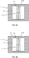
- FIG 6A shows an embodiment of a deformable frame 1 wherein the width Dy of part of the frame that is in contact with the actuator 2 is less than a width Dx of part of the frame parallel to the actuation direction. Changing a width of the frame can influence both the mass distribution M and stiffness distribution K.
- FIG 6B shows another embodiment of a deformable frame 1 with similar widths Dx,Dy.
- the deformable frame 1 comprises a recess local which may lower the stiffness distribution K at that location. It will be appreciated that by variation of the shape a desired combination of stiffness and mass distributions may be obtained to influence a normal mode and frequency of the deformable frame 1.
- the deformable frame 1 has a lower stiffness in a direction wherein the actuator 2 actuates the deformable frame 1 than in a direction perpendicular thereto. This can have an advantage that the parts of the deformable frame 1 remain more stationary, in particular, the thicker parts Dy may be less flexible than the thinner parts Dy.
- the stiffness or the rigidity of a structure is the extent to which it resists deformation in response to an applied force. Stiffness may be regarded as an extensive property of the structure, e.g. solid body, dependent on the material, shape, and boundary conditions. Behaviour of the constituent material itself can also be described by its elastic modulus. The stiffness can vary over the extent of the structure, e.g. some parts can be more flexible than others. While the stiffness may influence both the modal deformation and the static deformation, said influence is not necessarily the same. Accordingly, the relative position of mode nodal points and static nodal points can still be influenced by the stiffness distribution.
- the stiffness distribution may be related to the mass distribution, though it is not necessarily the same.
- the structure may typically also be more stiff.
- stiffness can be locally influenced by a particular shape of the structure while the mass is not changed.
- mass can be lumped onto a structure without appreciably influencing the stiffness, e.g. by adding the mass to the deformable frame in a direction perpendicular to the actuator motion.
- the mass distribution typically influences the modal deformation and mode nodal points while the static deformation is relatively unaffected. Accordingly, the relative position of the mode nodal points and static nodal points can be influenced by redistribution of mass, which however may also influence the stiffness distribution as noted above.
- FIG 7A shows a graph of a simulated deformable frame 1 in frontal view with coordinates (x,y).
- the circles indicate nodes used in the calculation of the beam element model, while the dashed lines indicate an extent of the frame beams.
- Simulated forces F are applied between the loops of the frame 1 over a width W as indicated.
- FIG 7B shows calculations of the relative positions of the static nodal points 11s and mode nodal points 11m.
- the graph on the left hand side of FIG 7B shows the positions x of nodal points as a function of the width W over which the force is distributed to the frame, as shown in FIG 7A .
- the width W e.g. by increasing the contact area between the actuator and deformable frame 1
- the static nodal point 11s can be moved while the mode nodal points 11m is unaffected. It will be appreciated that a distance dx between the static nodal point 11s and mode nodal point 11m can thus be decreased.
- the graph on the right hand side of FIG 7B shows the positions x of nodal points as a function of the mass Ma applied at the node of the applied force.
- the mode nodal point 11m can be shifted towards the static nodal points 11s thus decreasing the distance dx therein between.
- the method comprises simulating a deformable frame 1 having a stiffness distribution K and mass distribution M.
- the method further comprises simulating exerting a force distribution F onto the deformable frame 1.
- the force is simulated under static or quasi-static conditions, e.g. a static deformation with the applied force is compared to a situation wherein no force or force of a different magnitude is applied.
- quasi-static conditions may apply at a frequency well below any eigenfrequencies of the deformable frame, e.g. with a time-varying force having a frequency below 1 Hz.
- the method further comprises calculating positions of static nodal points 11s which are stationary during static deformation of the deformable frame 1 under said conditions.
- the method further comprises calculating vibrational eigenmodes of the deformable frame 1.
- an eigenmode is calculated or selected that couples to the force distribution F when a magnitude of the force distribution F is time-oscillated since this mode may affect the position of the stationary point.
- the method further comprises calculating positions of mode nodal points 11m at an interface 1s of the deformable frame 1 which are stationary during modal deformation of the deformable frame 1 in an excited state V0 of the said eigenmode V.
- the method further comprises calculating a distance dx between the static nodal points 11s and the mode nodal points 11m.
- the method further comprises varying one or more of the force distribution F, stiffness distribution K, and/or mass distribution M until the static nodal points 11s coincide with the mode nodal points 11m, e.g. are within a threshold distance.
- the method is stored on a computer-readable storage medium with program instructions that, when run on one or more computers, cause the one or more computers to perform the said method.
- an actuator module as described herein can thus be manufactured according to design specification wherein the static nodal points 11s coincide with the mode nodal points 11m, e.g. as obtained by the method described herein.
- the actuator module is manufactured by providing a deformable frame 1 with the stiffness distribution K and mass distribution M according to the design.
- one embodiment comprises providing an actuator 2 connected to the deformable frame 1 and arranged for exerting a time-varying force distribution F onto the deformable frame 1 via a connection 12 between the deformable frame 1 and the actuator 2, wherein the force distribution F at least under quasi-static conditions is arranged according to the design.
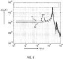
- FIG 8 shows a graph of frequency transfer functions 81 and 82.
- the frequency transfer functions 81 corresponds to a conventional connection between a actuator module and base frame. It may be observed that transfer functions 81 comprises a number of resonances, 81r caused by resonances in the base frame.
- the frequency transfer functions 82 corresponds to a actuator module optimized according to the present disclosure. It will be appreciated that the transfer function is more smooth and does not suffer from the resonances 81r. Accordingly, its behaviour can be more predictable so it can be more easily modelled and/or calibrated.
- FIG 9A shows a schematic cross-section view of one embodiment of a connection 30 between the actuator module 10 and base frame 20.
- the deformable frame 1 of the actuator module 10 comprises a protrusion 3p centred on the coinciding nodal point or line 11m, 11s.
- the base frame 20 comprises a corresponding recess 23r that engages the protrusion 3p to hold the actuator module 10.
- FIG 9B shows a schematic cross-section view of another embodiment of a connection 30 between the actuator module 10 and base frame 20.
- the deformable frame 1 of the actuator module 10 comprises a recess 3r centred on the coinciding nodal point or line 11m,11s.
- the base frame 20 also comprises recess 23r. The two recesses 3r and 23r may engage each other via a ball 3b to hold the actuator module 10.
- a real point contact between the deformable frame 1 and base frame 20 can be difficult to achieve.
- the transferred motion to the base frame can be minimized. This may further prevent that vibrations of the base frame are excited.
- connection 30 between the actuator module 10 and base frame 20 allows rotation around the respective coinciding nodal point 11m, 11s. This may prevent that rotational vibrations are passed via the connection 30 between the actuator module 10 and base frame 20.
- connection 30 between the actuator module 10 and base frame 20 comprises an anti-frictional layer, e.g. teflon or a ceramic top layer.
- the connection 30 comprises a steel ball.
- a contact surface can be reduced.
- the connection 30 comprises a groove shaped recess on a side of the base frame 20.
- a protrusion on a side of the deformable frame 1 may still translate in the direction of the groove; this way internal stresses can be avoided.
- connection 30 between the actuator module 10 and base frame 20 is arranged to allow translation in a direction of the connection 30, i.e. transverse to the surface 1 in a direction of the dashed nodal line. This may prevent that vibrations transverse to the actuating direction of the actuator (not shown here) are passed via the connection 30 between the actuator module 10 and base frame 20.
- the axis of rotation is centred around the stationary point and the friction along this rotation is minimized. This may thus closely mimic suspension on a perfect point. Still, the dimensions are preferably chosen as small as possible. Preferably, the diameter "D" of the engaging area between the deformable frame 1 and base frame 20 is smaller than 1 mm, or even smaller than 0.1 mm.
- FIG 10A shows another embodiment an actuator system 100 comprising a base frame 20 holding an actuator module 10 according to any of the previous claims, wherein the actuator module 10 is connected to the base frame 20 by engaging respective frame connectors 3 on the interface 1s of the deformable frame 1.
- the force distribution is variable along a dimension Z of the frame 1 that is transverse to dimensions X,Y of the interface 1s where the frame connectors 3 engage.
- multiple actuators 2 are placed along the depth dimension of the frame Z to provide a respective force F1,F2,F3.
- three voice coil actuators are located along the depth of the deformable frame, and the force distribution over these voice coils is used to control the static deformation.
- the force distribution F1,F2,F3 is adapted along a dimension transverse to the interface 1s to have the static nodal points coincide with the mode nodal points (not shown).
- FIG 10B shows a zoomed-in view of an embodiment for attaching the base frame 20 to the actuator module 10.
- a small pin 3 is screwed inside the deformable frame 1 at the location of the nodal point and then clamped at the side of the base frame.
- the interface 1s of the actuator module comprises multiple recesses to test the effect of placement of the pin 3 at different positions and to find the optimum e.g. at or near the nodal points.
Landscapes
- Physics & Mathematics (AREA)
- General Physics & Mathematics (AREA)
- Engineering & Computer Science (AREA)
- Health & Medical Sciences (AREA)
- General Health & Medical Sciences (AREA)
- Nuclear Medicine, Radiotherapy & Molecular Imaging (AREA)
- Radiology & Medical Imaging (AREA)
- Theoretical Computer Science (AREA)
- General Engineering & Computer Science (AREA)
- Computer Hardware Design (AREA)
- Evolutionary Computation (AREA)
- Geometry (AREA)
- Mathematical Physics (AREA)
- Mechanical Light Control Or Optical Switches (AREA)
- Micromachines (AREA)
- Computational Mathematics (AREA)
- Mathematical Analysis (AREA)
- Mathematical Optimization (AREA)
- General Electrical Machinery Utilizing Piezoelectricity, Electrostriction Or Magnetostriction (AREA)
- Pure & Applied Mathematics (AREA)
- Data Mining & Analysis (AREA)
- Operations Research (AREA)
- Algebra (AREA)
- Databases & Information Systems (AREA)
- Software Systems (AREA)
Claims (14)
- Aktormodul (10) zur Betätigung einer Last (14), wobei das Aktormodul (10) Folgendes umfasst- einen verformbaren Rahmen (1) mit einer Steifigkeitsverteilung (K) und einer Massenverteilung (M), die einen Schwingungseigenmodus (V) des verformbaren Rahmens (1) bestimmen, wobei eine Grenzfläche (1s) durch eine Oberfläche des verformbaren Rahmens (1) mehrere Modusknotenpunkte (11m) aufweist, die während einer modalen Verformung des verformbaren Rahmens (1) in einem angeregten Zustand (V0) des Eigenmodus (V) stationär sind; und- einen Aktor (2), der mit dem verformbaren Rahmen (1) verbunden ist und zum Ausüben einer zeitlich variierenden Kraftverteilung (F) auf den verformbaren Rahmen (1) über eine Verbindung (12) zwischen dem verformbaren Rahmen (1) und dem Aktor (2) eingerichtet ist, wobei die Grenzfläche (1s) des verformbaren Rahmens (1) mehrere statische Knotenpunkte (11s) aufweist, die während der statischen Verformung des verformbaren Rahmens (1) stationär sind, wenn die von dem Aktor (2) ausgeübte zeitlich variierende Kraftverteilung (F) unter quasistatischen Bedingungen bei Frequenzen deutlich unterhalb der niedrigsten Eigenfrequenz des verformbaren Rahmens (1) aufgebracht wird;- wobei die zeitlich variierende Kraftverteilung (F) dazu eingerichtet ist, sich an den angeregten Zustand (V0) des Eigenmodus (V) anzukoppeln und der verformbare Rahmen (1) eine Betätigungsfläche (13) umfasst, die im Gebrauch aufgrund der kombinierten modalen und statischen Verformungen des verformbaren Rahmens (1) oszilliert, um die Last (14) zu betätigen, die die Betätigungsfläche (13) berührt und/oder mit dieser verbunden ist; und- wobei die Kraftverteilung (F), die Steifigkeitsverteilung (K) und/oder die Massenverteilung (M) so angepasst sind, dass die statischen Knotenpunkte (11s) mit den Modusknotenpunkten (11m) über eine Dimension innerhalb eines Toleranzabstands (dx) von weniger als einem Prozent einer maximalen Größe (X) über die Grenzfläche (1s) des verformbaren Rahmens (1) in dieser Dimension zusammenfallen;- wobei der verformbare Rahmen (1) mehrere Rahmenverbinder (3) zum Verbinden des Aktormoduls mit einem Grundrahmen (20) umfasst, wobei die Rahmenverbinder (3) an der Grenzfläche (1s) des verformbaren Rahmens (1) zentriert auf den statischen Knotenpunkten (11s) und/oder den Modusknotenpunkten (11m) eingerichtet sind.
- Aktormodul (10) nach Anspruch 1, wobei jeder Rahmenverbinder (3) eine jeweilige Aussparung und/oder einen Vorsprung aufweist, die bzw. der auf den statischen Knotenpunkten (11s) und/oder Modusknotenpunkten (11m) zentriert ist, um den verformbaren Rahmen (1) über die Aussparung und/oder den Vorsprung zu halten.
- Aktormodul (10) nach Anspruch 1 oder 2, wobei die Rahmenverbinder (3) rotationssymmetrisch um die statischen Knotenpunkte (11s) und/oder Modusknotenpunkte (11m) sind.
- Aktormodul (10) nach einem der vorhergehenden Ansprüche, wobei die Verbindung (12) zwischen dem Aktor (2) und dem verformbaren Rahmen (1) auf einem Modus-Antiknoten (11a) des verformbaren Rahmens (1) zentriert ist, die eine Position auf einer Oberfläche des verformbaren Rahmens (1) ist, an der die modale Verformung des verformbaren Rahmens (1) im angeregten Zustand (V0) des Eigenmodus (V) maximal ist.
- Aktormodul (10) nach einem der vorhergehenden Ansprüche, wobei der verformbare Rahmen (1) eine spiegelsymmetrische Struktur aufweist, bei der eine gleiche aber entgegengesetzte Kraftverteilung (F) auf jede Seite (12, 12') der spiegelsymmetrischen Struktur durch einen oder mehrere Aktoren (2) dazwischen aufgebracht wird, wobei die Kraftverteilungen (F) zu einer gleichen aber entgegengesetzten Verformung der spiegelsymmetrischen Struktur führen.
- Aktormodul (10) nach einem der vorhergehenden Ansprüche, umfassend wenigstens zwei Aktoren (2a, 2b), die in entgegengesetzten Richtungen arbeiten, um gleiche, aber entgegengesetzte Kraftverteilungen (F) auf verschiedene Seiten (12a, 12b) des verformbaren Rahmens (1) aufzubringen.
- Aktorsystem (100) mit einem Grundrahmen (20), der ein Aktormodul (10) nach einem der vorhergehenden Ansprüche hält, wobei das Aktormodul (10) mit dem Grundrahmen (20) durch Ineingriffbringen entsprechender Rahmenverbinder (3) an der Grenzfläche (1s) des verformbaren Rahmens (1) verbunden ist.
- Aktorsystem (100) nach Anspruch 7, wobei eine Verbindung (30) zwischen dem Aktormodul (10) und dem Grundrahmen (20) um einen jeweiligen statischen Knotenpunkt (11s) und/oder Modusknotenpunkt (11m) drehfrei ist.
- Aktorsystem (100) nach Anspruch 7 oder 8, umfassend ein Translations- und/oder Rotationssystem (22) zwischen dem Grundrahmen (20) und einer stationären Basis (25) zur gesteuerten Translation und/oder Rotation des Grundrahmens (20)) in Bezug auf die ortsfeste Basis (25).
- Aktorsystem (100) nach einem der Ansprüche 7 bis 9, wobei der Grundrahmen (20) mit mehreren Aktormodulen (10a, 10b, 10c) verbunden ist.
- Atomkraftmikroskopie (AFM-System) mit einem Aktorsystem (100) nach einem der Ansprüche 7 bis 10, wobei die Betätigungsfläche (13) zum Betätigen einer Sondenspitze (14) zum Abtasten einer Probenfläche (15) eingerichtet ist.
- Computerimplementiertes Verfahren zum Entwerfen eines Aktormoduls (10), wobei das Verfahren Folgendes umfasst:- Simulieren eines verformbaren Rahmens (1) mit einer Steifigkeitsverteilung (K) und einer Massenverteilung (M);- Simulieren des Ausübens einer Kraftverteilung (F) auf den verformbaren Rahmen (1) unter quasistatischen Bedingungen bei Frequenzen deutlich unterhalb der niedrigsten Eigenfrequenz des verformbaren Rahmens (1);- Berechnen von Positionen von statischen Knotenpunkten (11s), die während der statischen Verformung des verformbaren Rahmens (1) unter den quasistatischen Bedingungen stationär sind;- Berechnen eines Schwingungseigenmodus (V) des verformbaren Rahmens (1), der mit der Kraftverteilung (F) gekoppelt ist, wenn eine Größe der Kraftverteilung (F) zeitlich oszilliert;- Berechnen von Positionen von Modusknotenpunkten (11m) an einer Grenzfläche (1s), die durch eine Oberfläche des verformbaren Rahmens (1) gebildet wird, die während der modalen Verformung des verformbaren Rahmens (1) in einem angeregten Zustand (V0) des Eigenmodus stationär sind (V);- Berechnen eines Abstands zwischen den statischen Knotenpunkten (11s) und den Modusknotenpunkten (11m) und Variieren der Kraftverteilung (F), der Steifigkeitsverteilung (K) und/oder der Massenverteilung (M) bis die statischen Knotenpunkte (11s) mit den Modusknotenpunkten (11m) über eine Dimension innerhalb eines Toleranzabstands (dx) von weniger als einem Prozent einer maximalen Größe (X) über die Grenzfläche (1s) des verformbaren Rahmens (l) in dieser Dimension zusammenfallen.
- Nichtflüchtiges computerlesbares Speichermedium mit Programmanweisungen, die, wenn sie auf einem oder mehreren Computern ausgeführt werden, bewirken, dass der eine oder die mehreren Computer das Verfahren nach Anspruch 12 auszuführen.
- Verfahren zur Herstellung eines Aktormoduls (10) umfassend- Entwerfen eines Aktormoduls nach dem Entwurfsverfahren nach Anspruch 12, wobei die Kraftverteilung (F), die Steifigkeitsverteilung (K) und die Massenverteilung (M) so angepasst sind, dass die statischen Knotenpunkte (11s) mit den Modusknotenpunkten (11m) übereinstimmen;- Versehen eines verformbaren Rahmens (1) mit der Steifigkeitsverteilung (K) und Massenverteilung (M) gemäß der Auslegung;- Bereitstellen eines Aktors (2), der mit dem verformbaren Rahmen (1) verbunden ist und zum Ausüben einer zeitlich variierenden Kraftverteilung (F) auf den verformbaren Rahmen (1) über eine Verbindung (12) zwischen dem verformbaren Rahmen (1) und dem Aktor (2) eingerichtet ist, wobei die Kraftverteilung (F) wenigstens unter quasistatischen Bedingungen bei Frequenzen deutlich unterhalb der niedrigsten Eigenfrequenz des verformbaren Rahmens entsprechend der Auslegung eingerichtet ist.
Applications Claiming Priority (2)
| Application Number | Priority Date | Filing Date | Title |
|---|---|---|---|
| EP14163625 | 2014-04-04 | ||
| PCT/NL2015/050206 WO2015152716A1 (en) | 2014-04-04 | 2015-03-31 | Actuator module for actuating a load |
Publications (2)
| Publication Number | Publication Date |
|---|---|
| EP3126849A1 EP3126849A1 (de) | 2017-02-08 |
| EP3126849B1 true EP3126849B1 (de) | 2020-02-12 |
Family
ID=50486773
Family Applications (1)
| Application Number | Title | Priority Date | Filing Date |
|---|---|---|---|
| EP15719859.9A Active EP3126849B1 (de) | 2014-04-04 | 2015-03-31 | Aktuatormodul zum ansteuern einer last |
Country Status (4)
| Country | Link |
|---|---|
| US (1) | US9880194B2 (de) |
| EP (1) | EP3126849B1 (de) |
| TW (1) | TWI667565B (de) |
| WO (1) | WO2015152716A1 (de) |
Families Citing this family (5)
| Publication number | Priority date | Publication date | Assignee | Title |
|---|---|---|---|---|
| CN111458629B (zh) * | 2019-01-21 | 2022-03-29 | 平高集团有限公司 | 一种高压开关机械故障的反演方法及装置 |
| CN110737947A (zh) * | 2019-10-10 | 2020-01-31 | 成都大运汽车集团有限公司 | 汽车车架性能评估方法 |
| EP3892885A1 (de) * | 2020-04-09 | 2021-10-13 | Nederlandse Organisatie voor toegepast- natuurwetenschappelijk Onderzoek TNO | Vorrichtung zur befestigung einer last an einem träger, anordnung, fahrzeug und verfahren |
| CN118176462A (zh) * | 2021-11-03 | 2024-06-11 | Asml荷兰有限公司 | 光刻设备平台联接件 |
| CN116738609B (zh) * | 2023-06-05 | 2024-04-09 | 哈尔滨工业大学 | 一种大型激振平台的支撑结构设计方法 |
Family Cites Families (11)
| Publication number | Priority date | Publication date | Assignee | Title |
|---|---|---|---|---|
| FR2709213B1 (fr) | 1993-08-18 | 1995-10-27 | Figest Bv | Moteur électrique à éléments vibrants et coupleur élastique. |
| JPH08280185A (ja) | 1995-04-07 | 1996-10-22 | Nikon Corp | 超音波アクチュエータ |
| EP1316803A3 (de) * | 1998-12-02 | 2005-11-09 | Formfactor, Inc. | Lithographische Kontaktelemente |
| US7084650B2 (en) * | 2002-12-16 | 2006-08-01 | Formfactor, Inc. | Apparatus and method for limiting over travel in a probe card assembly |
| US7342402B2 (en) * | 2003-04-10 | 2008-03-11 | Formfactor, Inc. | Method of probing a device using captured image of probe structure in which probe tips comprise alignment features |
| TWI232944B (en) * | 2003-10-17 | 2005-05-21 | Ind Tech Res Inst | MEMS differential actuated scanning nano probe |
| US7117724B1 (en) * | 2004-04-07 | 2006-10-10 | James G. Goodberlet | Flexure-beam actuator and stage for micro- and nano-positioning |
| CN100498803C (zh) * | 2007-01-26 | 2009-06-10 | 西北工业大学 | 空间连续变形mems的可重用参数化组件建模方法 |
| US7969065B2 (en) | 2008-09-09 | 2011-06-28 | Canon Kabushiki Kaisha | Vibration wave driving device |
| US8662764B2 (en) * | 2012-06-14 | 2014-03-04 | Georgia Tech Research Corporation | Camera positioning mechanism using an antagonistic pair of compliant contractile actuators |
| TWI447399B (zh) * | 2012-09-19 | 2014-08-01 | 矽品精密工業股份有限公司 | 具有微探針之半導體裝置及其製法 |
-
2015
- 2015-03-31 WO PCT/NL2015/050206 patent/WO2015152716A1/en not_active Ceased
- 2015-03-31 EP EP15719859.9A patent/EP3126849B1/de active Active
- 2015-03-31 US US15/301,454 patent/US9880194B2/en active Active
- 2015-04-02 TW TW104110890A patent/TWI667565B/zh active
Non-Patent Citations (1)
| Title |
|---|
| None * |
Also Published As
| Publication number | Publication date |
|---|---|
| US20170108531A1 (en) | 2017-04-20 |
| US9880194B2 (en) | 2018-01-30 |
| TW201543194A (zh) | 2015-11-16 |
| WO2015152716A1 (en) | 2015-10-08 |
| EP3126849A1 (de) | 2017-02-08 |
| TWI667565B (zh) | 2019-08-01 |
Similar Documents
| Publication | Publication Date | Title |
|---|---|---|
| EP3126849B1 (de) | Aktuatormodul zum ansteuern einer last | |
| Polit et al. | Development of a high-bandwidth XY nanopositioning stage for high-rate micro-/nanomanufacturing | |
| US7137291B2 (en) | Multi-dimensional force sensing for scanning probe microscopy using carbon nanotube tips and carbon nanotube oscillators | |
| Kim et al. | Development of a novel 3-degrees of freedom flexure based positioning system | |
| US8763475B2 (en) | Active damping of high speed scanning probe microscope components | |
| Wadikhaye et al. | A serial-kinematic nanopositioner for high-speed atomic force microscopy | |
| US7610797B2 (en) | Carbon nanotube detection system | |
| Lyu et al. | Design of a compliant vertical micropositioning stage based on lamina emergent mechanisms | |
| KR101340033B1 (ko) | 유연기구 메커니즘을 이용한 3축 면외방향 운동 스테이지 | |
| Alblalaihid et al. | Variable stiffness probing systems for micro-coordinate measuring machines | |
| Yong et al. | Mechanical design of high-speed nanopositioning systems | |
| Gunnink et al. | Performance optimization of large stroke flexure hinges for high stiffness and eigenfrequency | |
| Alblalaihid et al. | Fabrication and characterisation of a novel smart suspension for micro-CMM probes | |
| US7406859B2 (en) | Adaptable end effector for atomic force microscopy based nano robotic manipulators | |
| Shen et al. | Dynamic Analysis of a 5‐DOF Flexure‐Based Nanopositioning Stage | |
| JP4498285B2 (ja) | 走査型プローブ装置 | |
| Van Riel et al. | Analysis of the measurement sensitivity of multidimensional vibrating microprobes | |
| Tian et al. | Development of a novel 3-DOF suspension mechanism for multi-function stylus profiling systems | |
| Kenton et al. | Design, characterization, and control of a monolithic three-axis high-bandwidth nanopositioning stage | |
| Bosetti et al. | Design, manufacturing, and performance verification of a Roberts linkage for inertial isolation | |
| TW201923353A (zh) | 用於掃描式探針顯微術系統中的z位置移動台、掃描頭及製造方法 | |
| Chen et al. | Design and analysis of a 3-DOF damped flexure-guided nanopositioning stage | |
| JP4439965B2 (ja) | パラレルリンク装置 | |
| Rhee et al. | Dynamics of thin-film piezoelectric vertical-rotational scanning actuator | |
| JP2005279798A (ja) | パラレルリンク装置のリンクおよびパラレルリンク装置 |
Legal Events
| Date | Code | Title | Description |
|---|---|---|---|
| STAA | Information on the status of an ep patent application or granted ep patent |
Free format text: STATUS: THE INTERNATIONAL PUBLICATION HAS BEEN MADE |
|
| PUAI | Public reference made under article 153(3) epc to a published international application that has entered the european phase |
Free format text: ORIGINAL CODE: 0009012 |
|
| STAA | Information on the status of an ep patent application or granted ep patent |
Free format text: STATUS: REQUEST FOR EXAMINATION WAS MADE |
|
| 17P | Request for examination filed |
Effective date: 20161101 |
|
| AK | Designated contracting states |
Kind code of ref document: A1 Designated state(s): AL AT BE BG CH CY CZ DE DK EE ES FI FR GB GR HR HU IE IS IT LI LT LU LV MC MK MT NL NO PL PT RO RS SE SI SK SM TR |
|
| AX | Request for extension of the european patent |
Extension state: BA ME |
|
| DAV | Request for validation of the european patent (deleted) | ||
| DAX | Request for extension of the european patent (deleted) | ||
| GRAP | Despatch of communication of intention to grant a patent |
Free format text: ORIGINAL CODE: EPIDOSNIGR1 |
|
| STAA | Information on the status of an ep patent application or granted ep patent |
Free format text: STATUS: GRANT OF PATENT IS INTENDED |
|
| INTG | Intention to grant announced |
Effective date: 20190830 |
|
| RIN1 | Information on inventor provided before grant (corrected) |
Inventor name: CROWCOMBE, WILLIAM EDWARD Inventor name: PEREBOOM, HAJO PIETER Inventor name: WITVOET, GERRIT Inventor name: VAN DEN DOOL, TEUNIS CORNELIS Inventor name: DE LANGE, THEODORUS JACOBUS |
|
| GRAS | Grant fee paid |
Free format text: ORIGINAL CODE: EPIDOSNIGR3 |
|
| GRAA | (expected) grant |
Free format text: ORIGINAL CODE: 0009210 |
|
| STAA | Information on the status of an ep patent application or granted ep patent |
Free format text: STATUS: THE PATENT HAS BEEN GRANTED |
|
| AK | Designated contracting states |
Kind code of ref document: B1 Designated state(s): AL AT BE BG CH CY CZ DE DK EE ES FI FR GB GR HR HU IE IS IT LI LT LU LV MC MK MT NL NO PL PT RO RS SE SI SK SM TR |
|
| REG | Reference to a national code |
Ref country code: GB Ref legal event code: FG4D |
|
| REG | Reference to a national code |
Ref country code: CH Ref legal event code: EP |
|
| REG | Reference to a national code |
Ref country code: AT Ref legal event code: REF Ref document number: 1232850 Country of ref document: AT Kind code of ref document: T Effective date: 20200215 |
|
| REG | Reference to a national code |
Ref country code: DE Ref legal event code: R096 Ref document number: 602015046752 Country of ref document: DE |
|
| REG | Reference to a national code |
Ref country code: IE Ref legal event code: FG4D |
|
| REG | Reference to a national code |
Ref country code: NL Ref legal event code: FP |
|
| PG25 | Lapsed in a contracting state [announced via postgrant information from national office to epo] |
Ref country code: RS Free format text: LAPSE BECAUSE OF FAILURE TO SUBMIT A TRANSLATION OF THE DESCRIPTION OR TO PAY THE FEE WITHIN THE PRESCRIBED TIME-LIMIT Effective date: 20200212 Ref country code: FI Free format text: LAPSE BECAUSE OF FAILURE TO SUBMIT A TRANSLATION OF THE DESCRIPTION OR TO PAY THE FEE WITHIN THE PRESCRIBED TIME-LIMIT Effective date: 20200212 Ref country code: NO Free format text: LAPSE BECAUSE OF FAILURE TO SUBMIT A TRANSLATION OF THE DESCRIPTION OR TO PAY THE FEE WITHIN THE PRESCRIBED TIME-LIMIT Effective date: 20200512 |
|
| REG | Reference to a national code |
Ref country code: LT Ref legal event code: MG4D |
|
| PG25 | Lapsed in a contracting state [announced via postgrant information from national office to epo] |
Ref country code: SE Free format text: LAPSE BECAUSE OF FAILURE TO SUBMIT A TRANSLATION OF THE DESCRIPTION OR TO PAY THE FEE WITHIN THE PRESCRIBED TIME-LIMIT Effective date: 20200212 Ref country code: LV Free format text: LAPSE BECAUSE OF FAILURE TO SUBMIT A TRANSLATION OF THE DESCRIPTION OR TO PAY THE FEE WITHIN THE PRESCRIBED TIME-LIMIT Effective date: 20200212 Ref country code: BG Free format text: LAPSE BECAUSE OF FAILURE TO SUBMIT A TRANSLATION OF THE DESCRIPTION OR TO PAY THE FEE WITHIN THE PRESCRIBED TIME-LIMIT Effective date: 20200512 Ref country code: GR Free format text: LAPSE BECAUSE OF FAILURE TO SUBMIT A TRANSLATION OF THE DESCRIPTION OR TO PAY THE FEE WITHIN THE PRESCRIBED TIME-LIMIT Effective date: 20200513 Ref country code: IS Free format text: LAPSE BECAUSE OF FAILURE TO SUBMIT A TRANSLATION OF THE DESCRIPTION OR TO PAY THE FEE WITHIN THE PRESCRIBED TIME-LIMIT Effective date: 20200612 Ref country code: HR Free format text: LAPSE BECAUSE OF FAILURE TO SUBMIT A TRANSLATION OF THE DESCRIPTION OR TO PAY THE FEE WITHIN THE PRESCRIBED TIME-LIMIT Effective date: 20200212 |
|
| PG25 | Lapsed in a contracting state [announced via postgrant information from national office to epo] |
Ref country code: SM Free format text: LAPSE BECAUSE OF FAILURE TO SUBMIT A TRANSLATION OF THE DESCRIPTION OR TO PAY THE FEE WITHIN THE PRESCRIBED TIME-LIMIT Effective date: 20200212 Ref country code: LT Free format text: LAPSE BECAUSE OF FAILURE TO SUBMIT A TRANSLATION OF THE DESCRIPTION OR TO PAY THE FEE WITHIN THE PRESCRIBED TIME-LIMIT Effective date: 20200212 Ref country code: EE Free format text: LAPSE BECAUSE OF FAILURE TO SUBMIT A TRANSLATION OF THE DESCRIPTION OR TO PAY THE FEE WITHIN THE PRESCRIBED TIME-LIMIT Effective date: 20200212 Ref country code: DK Free format text: LAPSE BECAUSE OF FAILURE TO SUBMIT A TRANSLATION OF THE DESCRIPTION OR TO PAY THE FEE WITHIN THE PRESCRIBED TIME-LIMIT Effective date: 20200212 Ref country code: SK Free format text: LAPSE BECAUSE OF FAILURE TO SUBMIT A TRANSLATION OF THE DESCRIPTION OR TO PAY THE FEE WITHIN THE PRESCRIBED TIME-LIMIT Effective date: 20200212 Ref country code: ES Free format text: LAPSE BECAUSE OF FAILURE TO SUBMIT A TRANSLATION OF THE DESCRIPTION OR TO PAY THE FEE WITHIN THE PRESCRIBED TIME-LIMIT Effective date: 20200212 Ref country code: CZ Free format text: LAPSE BECAUSE OF FAILURE TO SUBMIT A TRANSLATION OF THE DESCRIPTION OR TO PAY THE FEE WITHIN THE PRESCRIBED TIME-LIMIT Effective date: 20200212 Ref country code: PT Free format text: LAPSE BECAUSE OF FAILURE TO SUBMIT A TRANSLATION OF THE DESCRIPTION OR TO PAY THE FEE WITHIN THE PRESCRIBED TIME-LIMIT Effective date: 20200705 Ref country code: RO Free format text: LAPSE BECAUSE OF FAILURE TO SUBMIT A TRANSLATION OF THE DESCRIPTION OR TO PAY THE FEE WITHIN THE PRESCRIBED TIME-LIMIT Effective date: 20200212 |
|
| REG | Reference to a national code |
Ref country code: CH Ref legal event code: PL |
|
| REG | Reference to a national code |
Ref country code: DE Ref legal event code: R097 Ref document number: 602015046752 Country of ref document: DE |
|
| REG | Reference to a national code |
Ref country code: AT Ref legal event code: MK05 Ref document number: 1232850 Country of ref document: AT Kind code of ref document: T Effective date: 20200212 |
|
| PG25 | Lapsed in a contracting state [announced via postgrant information from national office to epo] |
Ref country code: MC Free format text: LAPSE BECAUSE OF FAILURE TO SUBMIT A TRANSLATION OF THE DESCRIPTION OR TO PAY THE FEE WITHIN THE PRESCRIBED TIME-LIMIT Effective date: 20200212 |
|
| PLBE | No opposition filed within time limit |
Free format text: ORIGINAL CODE: 0009261 |
|
| STAA | Information on the status of an ep patent application or granted ep patent |
Free format text: STATUS: NO OPPOSITION FILED WITHIN TIME LIMIT |
|
| REG | Reference to a national code |
Ref country code: BE Ref legal event code: MM Effective date: 20200331 |
|
| PG25 | Lapsed in a contracting state [announced via postgrant information from national office to epo] |
Ref country code: LU Free format text: LAPSE BECAUSE OF NON-PAYMENT OF DUE FEES Effective date: 20200331 |
|
| 26N | No opposition filed |
Effective date: 20201113 |
|
| PG25 | Lapsed in a contracting state [announced via postgrant information from national office to epo] |
Ref country code: LI Free format text: LAPSE BECAUSE OF NON-PAYMENT OF DUE FEES Effective date: 20200331 Ref country code: IT Free format text: LAPSE BECAUSE OF FAILURE TO SUBMIT A TRANSLATION OF THE DESCRIPTION OR TO PAY THE FEE WITHIN THE PRESCRIBED TIME-LIMIT Effective date: 20200212 Ref country code: IE Free format text: LAPSE BECAUSE OF NON-PAYMENT OF DUE FEES Effective date: 20200331 Ref country code: CH Free format text: LAPSE BECAUSE OF NON-PAYMENT OF DUE FEES Effective date: 20200331 Ref country code: AT Free format text: LAPSE BECAUSE OF FAILURE TO SUBMIT A TRANSLATION OF THE DESCRIPTION OR TO PAY THE FEE WITHIN THE PRESCRIBED TIME-LIMIT Effective date: 20200212 |
|
| PG25 | Lapsed in a contracting state [announced via postgrant information from national office to epo] |
Ref country code: SI Free format text: LAPSE BECAUSE OF FAILURE TO SUBMIT A TRANSLATION OF THE DESCRIPTION OR TO PAY THE FEE WITHIN THE PRESCRIBED TIME-LIMIT Effective date: 20200212 Ref country code: PL Free format text: LAPSE BECAUSE OF FAILURE TO SUBMIT A TRANSLATION OF THE DESCRIPTION OR TO PAY THE FEE WITHIN THE PRESCRIBED TIME-LIMIT Effective date: 20200212 Ref country code: BE Free format text: LAPSE BECAUSE OF NON-PAYMENT OF DUE FEES Effective date: 20200331 |
|
| PG25 | Lapsed in a contracting state [announced via postgrant information from national office to epo] |
Ref country code: TR Free format text: LAPSE BECAUSE OF FAILURE TO SUBMIT A TRANSLATION OF THE DESCRIPTION OR TO PAY THE FEE WITHIN THE PRESCRIBED TIME-LIMIT Effective date: 20200212 Ref country code: MT Free format text: LAPSE BECAUSE OF FAILURE TO SUBMIT A TRANSLATION OF THE DESCRIPTION OR TO PAY THE FEE WITHIN THE PRESCRIBED TIME-LIMIT Effective date: 20200212 Ref country code: CY Free format text: LAPSE BECAUSE OF FAILURE TO SUBMIT A TRANSLATION OF THE DESCRIPTION OR TO PAY THE FEE WITHIN THE PRESCRIBED TIME-LIMIT Effective date: 20200212 |
|
| PG25 | Lapsed in a contracting state [announced via postgrant information from national office to epo] |
Ref country code: MK Free format text: LAPSE BECAUSE OF FAILURE TO SUBMIT A TRANSLATION OF THE DESCRIPTION OR TO PAY THE FEE WITHIN THE PRESCRIBED TIME-LIMIT Effective date: 20200212 Ref country code: AL Free format text: LAPSE BECAUSE OF FAILURE TO SUBMIT A TRANSLATION OF THE DESCRIPTION OR TO PAY THE FEE WITHIN THE PRESCRIBED TIME-LIMIT Effective date: 20200212 |
|
| P01 | Opt-out of the competence of the unified patent court (upc) registered |
Effective date: 20230522 |
|
| PGFP | Annual fee paid to national office [announced via postgrant information from national office to epo] |
Ref country code: GB Payment date: 20260324 Year of fee payment: 12 |
|
| PGFP | Annual fee paid to national office [announced via postgrant information from national office to epo] |
Ref country code: DE Payment date: 20260319 Year of fee payment: 12 |
|
| PGFP | Annual fee paid to national office [announced via postgrant information from national office to epo] |
Ref country code: NL Payment date: 20260319 Year of fee payment: 12 |
|
| PGFP | Annual fee paid to national office [announced via postgrant information from national office to epo] |
Ref country code: FR Payment date: 20260320 Year of fee payment: 12 |