EP3127192B1 - Fiche modulaire - Google Patents
Fiche modulaire Download PDFInfo
- Publication number
- EP3127192B1 EP3127192B1 EP15720901.6A EP15720901A EP3127192B1 EP 3127192 B1 EP3127192 B1 EP 3127192B1 EP 15720901 A EP15720901 A EP 15720901A EP 3127192 B1 EP3127192 B1 EP 3127192B1
- Authority
- EP
- European Patent Office
- Prior art keywords
- connector
- plug connector
- module
- modules
- modular
- Prior art date
- Legal status (The legal status is an assumption and is not a legal conclusion. Google has not performed a legal analysis and makes no representation as to the accuracy of the status listed.)
- Active
Links
Images


Classifications
-
- H—ELECTRICITY
- H01—ELECTRIC ELEMENTS
- H01R—ELECTRICALLY-CONDUCTIVE CONNECTIONS; STRUCTURAL ASSOCIATIONS OF A PLURALITY OF MUTUALLY-INSULATED ELECTRICAL CONNECTING ELEMENTS; COUPLING DEVICES; CURRENT COLLECTORS
- H01R13/00—Details of coupling devices of the kinds covered by groups H01R12/70 or H01R24/00 - H01R33/00
- H01R13/66—Structural association with built-in electrical component
- H01R13/665—Structural association with built-in electrical component with built-in electronic circuit
-
- G—PHYSICS
- G06—COMPUTING OR CALCULATING; COUNTING
- G06F—ELECTRIC DIGITAL DATA PROCESSING
- G06F13/00—Interconnection of, or transfer of information or other signals between, memories, input/output devices or central processing units
- G06F13/38—Information transfer, e.g. on bus
- G06F13/40—Bus structure
- G06F13/4004—Coupling between buses
-
- H—ELECTRICITY
- H01—ELECTRIC ELEMENTS
- H01R—ELECTRICALLY-CONDUCTIVE CONNECTIONS; STRUCTURAL ASSOCIATIONS OF A PLURALITY OF MUTUALLY-INSULATED ELECTRICAL CONNECTING ELEMENTS; COUPLING DEVICES; CURRENT COLLECTORS
- H01R13/00—Details of coupling devices of the kinds covered by groups H01R12/70 or H01R24/00 - H01R33/00
- H01R13/46—Bases; Cases
- H01R13/514—Bases; Cases composed as a modular blocks or assembly, i.e. composed of co-operating parts provided with contact members or holding contact members between them
-
- H—ELECTRICITY
- H01—ELECTRIC ELEMENTS
- H01R—ELECTRICALLY-CONDUCTIVE CONNECTIONS; STRUCTURAL ASSOCIATIONS OF A PLURALITY OF MUTUALLY-INSULATED ELECTRICAL CONNECTING ELEMENTS; COUPLING DEVICES; CURRENT COLLECTORS
- H01R13/00—Details of coupling devices of the kinds covered by groups H01R12/70 or H01R24/00 - H01R33/00
- H01R13/46—Bases; Cases
- H01R13/516—Means for holding or embracing insulating body, e.g. casing, hoods
- H01R13/518—Means for holding or embracing insulating body, e.g. casing, hoods for holding or embracing several coupling parts, e.g. frames
-
- H—ELECTRICITY
- H01—ELECTRIC ELEMENTS
- H01R—ELECTRICALLY-CONDUCTIVE CONNECTIONS; STRUCTURAL ASSOCIATIONS OF A PLURALITY OF MUTUALLY-INSULATED ELECTRICAL CONNECTING ELEMENTS; COUPLING DEVICES; CURRENT COLLECTORS
- H01R13/00—Details of coupling devices of the kinds covered by groups H01R12/70 or H01R24/00 - H01R33/00
- H01R13/66—Structural association with built-in electrical component
- H01R13/665—Structural association with built-in electrical component with built-in electronic circuit
- H01R13/6683—Structural association with built-in electrical component with built-in electronic circuit with built-in sensor
Definitions
- the invention is based on a modular connector according to the preamble of independent claim 1.
- Such modular connectors are required to transmit signals and currents between cables and / or devices.
- signal and current-carrying cables or lines are connected to the modular connector.
- the modular connector is connected directly to the cable or mounted on a device as a so-called add-on housing.
- add-on housing In the case of a modular plug-in connector designed as an add-on housing, lines from the housing are fed directly into the modular plug-in connector without cables, and contact is made with it.
- Two such modular connectors are provided for mutual contact.
- mechanical contacting of the modular plug connectors with one another is provided, as well as contacting the signal and / or current-carrying lines by means of contact means that are accommodated in the modular plug connector.
- electrical contact means Depending on the design of the modular plug connector, electrical contact means, optical contact means, pneumatic contact means, inductive contact means or fluid contacts can be accommodated in the modular plug connector.
- Such modular connectors comprise a connector housing in which several different connector modules can be received.
- the connector modules standardized to a uniform module width.
- Connector modules can be designed with a single, double or multiple module width.
- the connector modules are received in the connector housing and thus form an individual mating face of the modular connector.
- the inclusion of the connector modules in a holding frame is widespread. This enables the connector modules to be easily assembled into a single modular insert. This modular insert can then be inserted in one piece into the connector housing and fixed in it.
- the DE 197 07 120 C1 shows a holding frame for holding connector modules and for installation in a connector housing or for screwing onto wall surfaces, the connector modules being inserted into the holding frame and holding means on the connector modules interacting with recesses provided on opposite wall parts (side parts) of the holding frame and the connector modules in a form-fitting manner hold the holding frame.
- DE202007018307U1 discloses a modular connector according to the preamble of claim 1.
- a connector unit for an electrical device comprising at least two current-carrying current paths when the device is in operation, each of which has a contact element with a plug contact body and a line connection electrically connected to the plug contact body and one with the line connection electrically
- Conductively connected line end piece of a supply cable leading to the device comprises a plug bridge with a contact carrier on which the contact elements are held so that the plug contact body on one side of the contact carrier and the Line connections are on the other side of the contact carrier, and a connector housing which encloses the connector bridge, the cable connections and the line end pieces to improve such that a current-related heating or heating of the contact elements can be detected as reliably as possible
- the connector unit at least one The first temperature sensor and at least one second temperature sensor comprises that the at least one first temperature sensor is thermally coupled to at least one of the current paths to a greater extent than the at least one second temperature sensor and that the at least one second temperature
- the pamphlet DE 20 2007 018 306 U1 discloses a measuring device for plug connectors, arranged in a plug connector housing in which electrical contacts are arranged in receiving openings of a contact insert provided for this purpose. At least one measuring sensor with an evaluation unit is assigned to one or more electrical contacts in the contact insert, the measuring sensor being arranged in the immediate vicinity of the electrical contact within the connector housing.
- MID technology Molded Interconnect Devices
- the use of MID technology is disclosed as an extremely space-saving variant, for example to apply and seal the required conductor tracks with the electronic components directly on a non-conductive module housing.
- the object of the invention is to present a modular connector that has electronics for measuring and evaluating physical quantities of the connector, the electronics being universally applicable and usable for an individual combination of the modular connector.
- the invention is a modular connector consisting of a connector housing, a holding frame and at least one connector module.
- the connector housing can have different embodiments.
- it can be a so-called add-on housing, which is provided for mounting on a housing wall and does not have a separate cable receptacle.
- Designs as add-on housings with additional cable receptacles are also conceivable.
- the holding frame is provided in the connector housing. This can be made in one piece with the connector housing or mechanically reversible fastened in the connector housing.
- the holding frame has at least one module slot which is provided for receiving connector modules.
- the holding frame can have one, two or more module slots. Modular connectors and associated holding frames with two, four, six or eight module slots have proven to be practical and advantageous.
- the connector modules for receiving in the holding frame can also have different sizes. In addition to the snap-in dimension of a module slot, double or multiple connector modules are useful.
- the connector modules comprise a module housing which can be designed in one or more parts.
- Contact means are provided in the module housing, which are provided for contacting and transmission of signals or currents.
- signal or current-carrying lines or wires are connected to the contact means on a connection side of the connector module.
- the contact means are accessible on a plug-in side of the connector module in order to be contacted with a corresponding connector module.
- the connector modules can have sensors which enable physical values to be recorded. These can be physical values of the contact means such as current, voltage, pressure, frequencies or temperature, but sensors for vibration, buttons for plug-in cycles or any other type of sensors are also conceivable.
- the modular connector has evaluation electronics which are suitable for processing the measured values recorded by the sensors. Any complex electronics that can perform a wide variety of tasks are conceivable.
- a bus system is provided in the modular connector for communication between the evaluation electronics and the sensors and / or connector modules. This makes it possible to connect a large number of different modules and sensors with the evaluation electronics.
- the bus system can be used to transfer energy and signals between sensors and the evaluation electronics.
- the evaluation electronics are enabled to automatically recognize the connected connector modules.
- the evaluation electronics can thus electronically map the physical configuration of the modular connector. An evaluation and processing of the measured values of various plug-in connector modules used is possible.
- the connector modules In order to enable a data bus between the evaluation electronics and the individual connector modules, the connector modules have additional electrical contact means in addition to the contact means for transmitting signals and currents. These additional contact means are provided on two opposite side surfaces of the connector modules. The electrical contact means on one side are electrically connected to those on the other side.
- the additional contact means allow connector modules arranged next to one another and received in the holding frame to make electrical contact with one another and thus form a data bus line.
- the sensors in the connector modules can be connected to the data bus line, which extends through all the plug connector modules used.
- the electrical contact means are designed as plug contacts (male contacts) on one side of the connector module.
- the electrical contact means provided on the opposite side, on the other hand, are designed as corresponding socket contacts (female contacts). This enables a large number of connector modules to be lined up.
- the data bus line can be looped through any number of connector modules.
- the data bus line is not provided by the connector modules, but is received in the holding frame.
- the connector modules can also be inserted into the holding frame by means of corresponding lines in the holding frame contact the data bus line. It is also possible to integrate the evaluation electronics into the holding frame.
- evaluation electronics also to be provided in a plug connector module.
- the evaluation electronics can be used in a modular manner in an existing modular connector.
- evaluation electronics in the snap-in dimension of the connector modules is that they can be connected directly to the data bus line, which extends through the connector modules, via electrical contact means on the side.
- the entire system can thus be integrated into existing connector housings with known holding frames.
- a communication interface into the module in order to be able to communicate with the evaluation electronics.
- This interface can optionally be implemented on the plug-in side in order to transmit the signals via plug-in contacts in a plug-in connector module of a contacting mating plug-in connector.
- an interface on the connection side is also conceivable, via which the signals are routed away by a connected cable.
- An additional embodiment provides for the interface for the evaluation electronics to be implemented by radio. This enables communication via WLAN, Bluetooth, RFID or other radio standards.
- a special embodiment of the invention provides that the evaluation electronics can be operated and read out by means of a bidirectional interface.
- a bidirectional interface can be integrated in the connector housing of the modular connector so that the evaluation electronics can be read out and programmed by an operator.
- a unit of keyboard and display or a touch-screen display can be used as a bidirectional interface, which combines the advantages of an optical display with the possibilities of direct input.
- the evaluation electronics can optionally be equipped with additional interfaces.
- additional memory or an interface for memory cards can be integrated.
- Such an interface for, for example, SD cards (Secure Digital Memory Card) can be used to transfer the collected data via the connector modules, measured values and working times to an external device (e.g. a computer or tablet PC) and evaluate them there.
- the data bus line is an I 2 C bus.
- the I 2 C bus consists of two bus lines and two lines for power supply. This arrangement is supplemented by a further, serial line between the connector modules, which is required for addressing the connector modules.
- bus systems are generally not suitable for use in such a small space as in a connector. Either the bus systems are very large and cannot be used in connector modules be accommodated. In addition, such bus systems usually have a very high energy consumption. Due to the very small size of connector modules, these systems cannot be used in the connector.
- bus systems such as the I 2 C bus
- I 2 C bus are generally not suitable for recognizing a geographical arrangement of slave modules.
- the slave modules usually have a unique ID or must be given an ID when connecting the bus system.
- Such a great effort would not be economical when assembling a modular connector.
- the compilation and configuration would have to be carried out by a specialist who is usually not on site in the field of electrical installation.
- the present invention therefore provides for all slave modules to be delivered without a unique ID.
- each module can be assigned a unique ID when the system is started. Much more, not only can each connector module be addressed individually, but the geographical sequence of the modules can also be determined and saved in the ID.
- the modular connector is configured by inserting different modules, so-called slave modules, next to each other in the connector and electrically connecting them.
- the first of the slave modules also contacts the evaluation electronics, which can also be located in a module.
- the configuration can be completed in different ways.
- the evaluation electronics of the master module wait a certain time after which it considers the configuration of the slave modules to be completed.
- a preferred further embodiment provides for the complete configuration to be recognized via what is known as an interrupt line.
- One of the bus lines can be used for this.
- a voltage is applied to this by the master module and measured at the same time. All connected slave modules have switched the interrupt line to ground in the initial state so that the master module cannot register any voltage.
- each slave module to which an ID is assigned separates the interrupt line. If all slave modules have been assigned an ID and have disconnected the interrupt line, the master module can register a voltage and thus conclude that the slave modules have been fully initialized.
- each slave module is assigned a unique ID.
- the IDs of the slave modules can be used to infer the physical sequence and thus the configuration of the modular connector can be inferred from the evaluation electronics in the master module.
- the evaluation electronics can select appropriate calculation and / or evaluation algorithms query and load a database that is matched to the slave modules and their sensors.
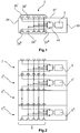
- FIG Figure 1 shows a connector module 2 in a simplified, schematic representation.
- elements of the connector module 2 known from the prior art, such as contacts and holding means 22, have been shown in FIG Figure 1 , as well as the Figures 2 and 3rd waived.
- the connector module 2 has a contact side 23 and a connection side 24 and is intended to be received in a holding frame 7, as in FIG Figure 4 is shown. To be received in the holding frame 7, the connector module 2 has holding means 22 which engage in recesses in the holding frame 7.
- holding frames 7 with different numbers of module slots 72 can be provided.
- six module slots 72 for receiving connector modules 2 are provided.
- the present invention can be applied to all of these solutions and is not limited to the embodiment shown.
- fastening means 71 are provided on the holding frame 7 in order to fasten and fix the holding frame 7 in a connector housing 1.
- the plug connector module 2 shown has, in addition to the elements known from the prior art, a sensor 3 according to the invention.
- the sensor 3 is provided for measuring physical measured variables in the connector module 2. Depending on the type and contacts of the connector module, different types of sensors 3 can be involved.
- Appropriate sensor types are: temperature sensors for monitoring overheating, current sensors for monitoring currents, vibration sensors for monitoring vibrations e.g. in trains, pressure sensors for monitoring pressures in pneumatic modules or a light sensor for monitoring light wave modules.
- the list can be expanded to include additional types of sensors.
- the sensor 3 is connected to electrical contact means 26 via electrical lines.
- An electronic component 42 can expediently be assigned to the sensor 3. This electronic component 42 can be used to convert the sensor data and to identify the Connector module 2 can be used. All electrical contact means 26 together form an electrical connection 25 on the connector module 2.
- the electrical contact means 26 are expediently provided on side surfaces 27 of the connector module 2.
- the sensor 3 is not only connected to an electrical connection 25, but also to a first electrical connection 25 'and a second electrical connection 25 ".
- Each of the electrical connections 25', 25" is on one of the side surfaces 27 ', 27 ". of the connector module 2.
- This arrangement allows the sensors 3 to be connected through the connector module 2. Contact can thus be made with the sensor 3 of the connector module 2 via the electrical connection 25 'and, at the same time, a further connector module 2 'be contacted with its sensor 3' on the connector module 2.
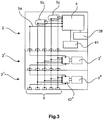
- the contacting of several connector modules 2, 2 ', 2 ", 2'” next to one another is in the Figure 2 shown.
- the four connector modules shown are arranged next to one another, as they would also be arranged in the holding frame 7.
- the side surfaces 27 'of the connector modules 2, 2', 2 ", 2 '” are each assigned to a side surface 27 "of a further connector module 2, 2', 2", 2 '".
- the electrical connections 25 'of the connector modules 2, 2', 2 ", 2 '” thus contact the electrical connections 25 "of the subordinate connector modules 2, 2', 2", 2 ".
- the electrical contact means 26 ' are the electrical connections 25 'preferably designed as pin contacts and the electrical contact means 26 "of the electrical connections 25" as socket contacts.
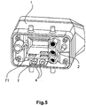
- the Figure 3 shows three further connector modules 2, 2 ', 2 "which as already in FIG Figure 2 shown arranged side by side and electrically contacted with one another. Only the connector modules 2 ', 2 "are equipped with sensors 3', 3".
- the connector module 2 is designed as a main or master module and has evaluation electronics 4.
- the evaluation electronics 4 are provided for evaluating and processing the measurement data from the sensors 3.
- the data bus line 5 is connected to the evaluation electronics 4.
- the data bus line 5 can have different individual lines depending on the design and type of bus system used. In the illustrated embodiments of the Figures 1, 2 and 3rd five individual lines are provided in the data bus line 5.
- the line 5a is a line running serially through all the connector modules 2 and used to identify the connector modules 2.
- the power lines 5b serve to supply power to the sensors 3 and electronic components 42.
- the data lines 5c are provided for communication between evaluation electronics 4 and electronic components 42.
- the connector module 2 has further components.
- a storage medium 41 is here intended. This can be used to store measured values or settings of the evaluation electronics 4. It is also conceivable to connect the storage medium 41 to the evaluation electronics 4 via a slot.
- an interface 28 is provided via which communication with the evaluation electronics 4 can take place.
- the interface 28 can be designed, for example, as a LAN interface, serial interface, WLAN interface or Bluetooth interface. Other types of interfaces are also conceivable.
- the Figure 5 shows a modular connector according to the invention with a view of the plug side.
- a plug connector housing 1 is shown with a holding frame 7 received therein.
- the holding frame 7 is held in the plug connector housing 1 via the fastening means 71.
- the fastening means 71 are screwed into the connector housing 1 by means of screws.
- the holding frame 7 shown is designed with three module slots 72, only one connector module 2 being received in the holding frame 7.
- the evaluation electronics 4 are provided in the connector housing 1 and attached to the inside thereof.
- the connector housing 2 has a bidirectional interface 6 which is let into a side wall of the connector housing 2.
- the lower area of the bidirectional interface 6 and the side wall of the connector housing 2 are shown in partial section for illustration.
- the bidirectional interface 6 can expediently be made available by a touch screen display which is connected to the evaluation electronics.
- the bidirectional interface 6 thus enables individual querying of measured values, as well as operation and programming of the evaluation electronics.
- a simple display or a display can also be integrated into the connector housing 1 as a bidirectional interface 6 and supplemented by an input device (for example keys or keyboard).
- an input device for example keys or keyboard.
Landscapes
- Engineering & Computer Science (AREA)
- Microelectronics & Electronic Packaging (AREA)
- General Engineering & Computer Science (AREA)
- Theoretical Computer Science (AREA)
- Computer Hardware Design (AREA)
- Physics & Mathematics (AREA)
- General Physics & Mathematics (AREA)
- Details Of Connecting Devices For Male And Female Coupling (AREA)
Claims (5)
- Connecteur enfichable modulaire, composé d'un boîtier de connecteur enfichable (1), d'un cadre de retenue (7), d'un système de bus et d'au moins un module de connecteur enfichable (2),
le cadre de retenue (7) présentant au moins un emplacement d'enfichage de module (72) dans lequel est disposé ledit au moins un module de connecteur enfichable (2),
une électronique d'évaluation (4) et au moins un capteur (3) étant prévus dans le module de connecteur enfichable (2),
une électronique de commande pour un système de bus étant intégrée dans l'électronique d'évaluation (4) et reliée électriquement audit au moins un capteur (3) par l'intermédiaire du système de bus,
ledit au moins un module de connecteur enfichable (2) disposant d'un adressage électronique qui est adapté pour communiquer par l'intermédiaire d'un système de bus, et
ledit au moins un module de connecteur enfichable (2) disposant d'au moins une borne électrique (25) pour un système de bus,
caractérisé en ce que le système de bus est intégré dans le cadre de retenue (7), le système de bus étant étendu par une ligne unique (5a) s'étendant en série à travers les modules de connecteur enfichable (2). - Connecteur enfichable modulaire selon la revendication 1, caractérisé en ce que le cadre de retenue (7) est fixé mécaniquement et de manière réversible dans le boîtier de connecteur enfichable (1) .
- Connecteur enfichable modulaire selon la revendication 1, caractérisé en ce que le cadre de retenue (7) est réalisé d'un seul tenant avec le boîtier de connecteur enfichable (1).
- Connecteur enfichable modulaire selon l'une quelconque des revendications précédentes, caractérisé en ce que l'électronique d'évaluation (4) reconnaît automatiquement des modules de connecteur enfichable (2) connectés au système de bus et peut lire des valeurs de capteur dudit au moins un capteur (3) disposé dans ledit au moins un module de connecteur enfichable (2).
- Connecteur enfichable modulaire selon l'une quelconque des revendications précédentes, caractérisé en ce que le système de bus est un système de bus I2C composé de deux lignes de données (5c) et de deux lignes électriques (5b).
Applications Claiming Priority (2)
| Application Number | Priority Date | Filing Date | Title |
|---|---|---|---|
| DE102014104629 | 2014-04-02 | ||
| PCT/DE2015/100143 WO2015149757A2 (fr) | 2014-04-02 | 2015-04-02 | Système de connecteur |
Publications (2)
| Publication Number | Publication Date |
|---|---|
| EP3127192A2 EP3127192A2 (fr) | 2017-02-08 |
| EP3127192B1 true EP3127192B1 (fr) | 2021-06-09 |
Family
ID=53054818
Family Applications (1)
| Application Number | Title | Priority Date | Filing Date |
|---|---|---|---|
| EP15720901.6A Active EP3127192B1 (fr) | 2014-04-02 | 2015-04-02 | Fiche modulaire |
Country Status (4)
| Country | Link |
|---|---|
| US (1) | US9847608B2 (fr) |
| EP (1) | EP3127192B1 (fr) |
| CN (1) | CN106463877B (fr) |
| WO (1) | WO2015149757A2 (fr) |
Families Citing this family (29)
| Publication number | Priority date | Publication date | Assignee | Title |
|---|---|---|---|---|
| DE102014111831A1 (de) * | 2014-08-19 | 2016-02-25 | Phoenix Contact E-Mobility Gmbh | Steckverbinderteil mit Temperatursensoren |
| DE102015105262A1 (de) * | 2015-04-08 | 2016-10-13 | Harting Electric Gmbh & Co. Kg | Kapazitives Sensormodul für einen Steckverbinder |
| DE102015114702B4 (de) * | 2015-09-03 | 2019-01-31 | Harting Electric Gmbh & Co. Kg | Halterahmen |
| DE102015114699A1 (de) | 2015-09-03 | 2017-03-09 | Harting Electric Gmbh & Co. Kg | Halterahmen für Steckverbindermodule |
| DE102015114696B4 (de) | 2015-09-03 | 2020-10-29 | Harting Electric Gmbh & Co. Kg | Halterahmen für Steckverbindermodule |
| DE102015114701B4 (de) | 2015-09-03 | 2019-01-31 | Harting Electric Gmbh & Co. Kg | Halterahmen mit Sperrelement |
| DE102015114700B4 (de) | 2015-09-03 | 2020-08-06 | Harting Electric Gmbh & Co. Kg | Halterahmen |
| RU2689123C1 (ru) | 2015-09-03 | 2019-05-24 | Хартинг Электрик Гмбх Унд Ко. Кг | Удерживающая рамка для модулей штекерного соединителя |
| DE102015114703B4 (de) | 2015-09-03 | 2020-03-26 | Harting Electric Gmbh & Co. Kg | Halterahmen für Steckverbindermodule |
| DE102015114697B4 (de) | 2015-09-03 | 2020-03-26 | Harting Electric Gmbh & Co. Kg | Halterahmen für Steckverbindermodule |
| DE102015222561B4 (de) * | 2015-11-16 | 2018-05-30 | Harting Electric Gmbh & Co. Kg | Halterahmen zur Halterung von Steckverbindermodulen |
| DE102016100794B4 (de) * | 2016-01-19 | 2019-03-28 | Harting Electric Gmbh & Co. Kg | Halterahmen mit Führungselement für Steckverbindermodule und System bestehend aus zwei dieser Halterahmen |
| DE102016104267B4 (de) * | 2016-03-09 | 2017-10-19 | Harting Electric Gmbh & Co. Kg | Strommessung im Isolierkörper |
| DE102016112519A1 (de) * | 2016-07-07 | 2018-01-11 | Harting Electric Gmbh & Co. Kg | Steckverbinderbauteil, Steckverbinder, Steckverbindersystem und Verfahren zum Zusammensetzen und Betreiben eines Steckverbinders |
| DE102016115665B3 (de) | 2016-08-24 | 2018-01-18 | Harting Electric Gmbh & Co. Kg | Steckverbinder |
| DE102017104864A1 (de) * | 2017-03-08 | 2018-09-13 | Harting Electric Gmbh & Co. Kg | Stromsensoranordnung und Verfahren |
| DE102017003198B4 (de) * | 2017-04-03 | 2018-10-31 | Harting Electric Gmbh & Co. Kg | Steckverbindermodularsystem mit integriertem Datenbus |
| BE1025564B1 (de) * | 2017-09-19 | 2019-04-19 | Phoenix Contact Gmbh & Co Kg | Modularer Anschlussblock mit einer Mehrzahl von Anschlussmodulen für ein Elektronikbauteil |
| DE102017125859A1 (de) * | 2017-11-06 | 2019-05-09 | Harting Electric Gmbh & Co. Kg | Modularer Halterahmen für Steckverbinder |
| DE102018101790A1 (de) * | 2018-01-26 | 2019-08-01 | Harting Electric Gmbh & Co. Kg | Dichteinsatz |
| CN108614457A (zh) * | 2018-05-29 | 2018-10-02 | 山东沃柏斯实验室工程有限公司 | 一种实验室专用控制柜 |
| DE102019133192A1 (de) * | 2019-12-05 | 2021-06-10 | Harting Electric Gmbh & Co. Kg | Verfahren zur Identifikation von Industriesteckverbindern |
| DE102020121752A1 (de) | 2020-08-19 | 2022-02-24 | Turck Holding Gmbh | Elektrischer Steckverbinder |
| CN113074808B (zh) * | 2021-03-24 | 2024-06-04 | 深圳市铱程机电设备有限公司 | 一种方便拆装调试的无线振动监测装置 |
| DE102021117401A1 (de) * | 2021-07-06 | 2023-01-12 | Harting Electric Stiftung & Co. Kg | Steckverbindergehäuse für elektronische datenleitungen |
| DE102021117400A1 (de) | 2021-07-06 | 2023-01-12 | Harting Electric Stiftung & Co. Kg | Industriesteckverbinder mit einem Datendiodenmodul |
| DE102022100272A1 (de) * | 2022-01-07 | 2023-07-13 | Weidmüller Interface GmbH & Co. KG | Intelligente modulare Steckverbindung |
| DE102023101556A1 (de) | 2023-01-23 | 2024-07-25 | Harting Electric Stiftung & Co. Kg | Hochstromsteckverbindersystem mit einstellbarer Trennkraft |
| JP2026503502A (ja) | 2023-02-20 | 2026-01-29 | ハルティング エレクトリック シュティフトゥング ウント コー. カー・ゲー | コネクタ離脱抵抗機構 |
Citations (1)
| Publication number | Priority date | Publication date | Assignee | Title |
|---|---|---|---|---|
| US5761052A (en) * | 1995-11-30 | 1998-06-02 | The Whitaker Corporation | Interconnection system for electronic controllers to a bus |
Family Cites Families (10)
| Publication number | Priority date | Publication date | Assignee | Title |
|---|---|---|---|---|
| DE19707120C1 (de) * | 1997-02-22 | 1998-06-25 | Harting Kgaa | Halterahmen |
| DE10107100A1 (de) | 2001-02-13 | 2002-12-05 | Profichip Gmbh | Steckvorrichtung mit integrierter Diagnose- und Auswerteschaltung und zuschaltbarem Abschlusswiderstand |
| DE20205787U1 (de) | 2002-04-13 | 2002-07-25 | HARTING Electric GmbH & Co. KG, 32339 Espelkamp | Modularer Steckverbinder |
| JP4126240B2 (ja) * | 2003-03-17 | 2008-07-30 | 矢崎総業株式会社 | 回路板組立構造 |
| DE102005049483B4 (de) | 2005-10-13 | 2007-10-18 | Ifm Electronic Gmbh | Elektrischen Stecker und Verfahren zur dezentralen Speicherung der Parameter eines Sensors |
| DE202005020026U1 (de) * | 2005-12-22 | 2006-03-16 | Harting Electric Gmbh & Co. Kg | Halterahmen für Steckermodule |
| DE202007018307U1 (de) * | 2007-03-24 | 2008-06-12 | Harting Electric Gmbh & Co. Kg | Messeinrichtung für Steckverbinder |
| DE202007018306U1 (de) * | 2007-03-24 | 2008-04-30 | Harting Electric Gmbh & Co. Kg | Messeinrichtung für modulare Steckverbinder |
| DE102012107902A1 (de) | 2012-08-28 | 2014-03-06 | Lapp Engineering & Co. | Steckereinheit und elektrisches Gerät mit einer derartigen Steckereinheit |
| ITMI20130462A1 (it) * | 2013-03-27 | 2014-09-28 | Westec S R L | Struttura di telaio di supporto per connettori modulari. |
-
2015
- 2015-04-02 EP EP15720901.6A patent/EP3127192B1/fr active Active
- 2015-04-02 CN CN201580018375.3A patent/CN106463877B/zh active Active
- 2015-04-02 US US15/301,671 patent/US9847608B2/en active Active
- 2015-04-02 WO PCT/DE2015/100143 patent/WO2015149757A2/fr not_active Ceased
Patent Citations (1)
| Publication number | Priority date | Publication date | Assignee | Title |
|---|---|---|---|---|
| US5761052A (en) * | 1995-11-30 | 1998-06-02 | The Whitaker Corporation | Interconnection system for electronic controllers to a bus |
Also Published As
| Publication number | Publication date |
|---|---|
| CN106463877B (zh) | 2019-01-22 |
| WO2015149757A2 (fr) | 2015-10-08 |
| US9847608B2 (en) | 2017-12-19 |
| WO2015149757A3 (fr) | 2015-11-26 |
| CN106463877A (zh) | 2017-02-22 |
| EP3127192A2 (fr) | 2017-02-08 |
| US20170141518A1 (en) | 2017-05-18 |
| WO2015149757A4 (fr) | 2016-01-21 |
Similar Documents
| Publication | Publication Date | Title |
|---|---|---|
| EP3127192A2 (fr) | Système de connecteur | |
| DE19535277C1 (de) | Baugruppe eines Automatisierungsgeräts | |
| EP1174781B1 (fr) | Appareil de transmission de signal | |
| DE202007018306U1 (de) | Messeinrichtung für modulare Steckverbinder | |
| DE202007018307U1 (de) | Messeinrichtung für Steckverbinder | |
| EP3844627B1 (fr) | Installation de commande et de transmission de données destinée à soutenir différents protocoles de communication et module d'adaptateur | |
| EP2009523A1 (fr) | Système de commande | |
| EP3607451A1 (fr) | Système modulaire de connecteurs enfichables comportant un bus de données intégré | |
| WO2018054869A1 (fr) | Système de compresseur pour véhicule utilitaire | |
| DE202007018305U1 (de) | Messeinrichtung an Steckkontakten | |
| EP1921328B1 (fr) | Dispositif de traitement d'air comprimé | |
| BE1025734B1 (de) | Modularer Steckverbinder austauschbarer Modul-Leiterplatte | |
| DE102016121598A1 (de) | Basismodul und Luftfahrtcomputersystem mit dem Basismodul | |
| WO2009118028A1 (fr) | Système modulaire électrique comprenant un module de bus de terrain à utilisation variable | |
| WO2001077534A1 (fr) | Commande de soupapes | |
| EP3178301B1 (fr) | Appareil de terrain de la technique d'automatisation | |
| DE102005016545A1 (de) | Modulrückwand für ein Schaltanlagenmodul, Schaltanlagenmodul und elektrische Schaltanlage | |
| DE19840596C1 (de) | Ventilanordnung mit mindestens einer aus mehreren elektrisch betätigbaren Ventilen bestehenden Ventileinheit | |
| DE102014204155A1 (de) | Vorrichtung zur Signalübertragung | |
| DE102018120823B3 (de) | Steuer- und Datenübertragungsanlage zur Unterstützung verschiedener Kommunikationsprotokolle und ein Adaptermodul | |
| EP2196670B1 (fr) | Appareil pouvant être connecté avec un composant sous vide | |
| EP2774163B1 (fr) | Disjoncteur doté d'au moins un contact de prise de tension | |
| EP2208120A1 (fr) | Système d'automatisation comprenant plusieurs composants d'automatisation formant un ensemble | |
| DE10007206A1 (de) | Zylinderschalter mit Datenübertragung über ein Hochfrequenzfeld | |
| DE102014102976A1 (de) | Leiterplatte und Anordnung zum elektrischen Verbinden einer Betriebselektronik |
Legal Events
| Date | Code | Title | Description |
|---|---|---|---|
| STAA | Information on the status of an ep patent application or granted ep patent |
Free format text: STATUS: THE INTERNATIONAL PUBLICATION HAS BEEN MADE |
|
| PUAI | Public reference made under article 153(3) epc to a published international application that has entered the european phase |
Free format text: ORIGINAL CODE: 0009012 |
|
| STAA | Information on the status of an ep patent application or granted ep patent |
Free format text: STATUS: REQUEST FOR EXAMINATION WAS MADE |
|
| 17P | Request for examination filed |
Effective date: 20160922 |
|
| AK | Designated contracting states |
Kind code of ref document: A2 Designated state(s): AL AT BE BG CH CY CZ DE DK EE ES FI FR GB GR HR HU IE IS IT LI LT LU LV MC MK MT NL NO PL PT RO RS SE SI SK SM TR |
|
| AX | Request for extension of the european patent |
Extension state: BA ME |
|
| RIN1 | Information on inventor provided before grant (corrected) |
Inventor name: TROEGER, LUTZ Inventor name: BRUEX, MARKUS Inventor name: FRIESEN, MARKUS |
|
| DAV | Request for validation of the european patent (deleted) | ||
| DAX | Request for extension of the european patent (deleted) | ||
| STAA | Information on the status of an ep patent application or granted ep patent |
Free format text: STATUS: EXAMINATION IS IN PROGRESS |
|
| 17Q | First examination report despatched |
Effective date: 20171027 |
|
| RIC1 | Information provided on ipc code assigned before grant |
Ipc: H01R 13/66 20060101ALI20201216BHEP Ipc: H01R 13/518 20060101ALI20201216BHEP Ipc: H01R 13/514 20060101AFI20201216BHEP Ipc: G06F 13/40 20060101ALI20201216BHEP |
|
| GRAP | Despatch of communication of intention to grant a patent |
Free format text: ORIGINAL CODE: EPIDOSNIGR1 |
|
| STAA | Information on the status of an ep patent application or granted ep patent |
Free format text: STATUS: GRANT OF PATENT IS INTENDED |
|
| INTG | Intention to grant announced |
Effective date: 20210127 |
|
| GRAS | Grant fee paid |
Free format text: ORIGINAL CODE: EPIDOSNIGR3 |
|
| GRAA | (expected) grant |
Free format text: ORIGINAL CODE: 0009210 |
|
| STAA | Information on the status of an ep patent application or granted ep patent |
Free format text: STATUS: THE PATENT HAS BEEN GRANTED |
|
| AK | Designated contracting states |
Kind code of ref document: B1 Designated state(s): AL AT BE BG CH CY CZ DE DK EE ES FI FR GB GR HR HU IE IS IT LI LT LU LV MC MK MT NL NO PL PT RO RS SE SI SK SM TR |
|
| REG | Reference to a national code |
Ref country code: GB Ref legal event code: FG4D Free format text: NOT ENGLISH |
|
| REG | Reference to a national code |
Ref country code: CH Ref legal event code: EP Ref country code: AT Ref legal event code: REF Ref document number: 1401249 Country of ref document: AT Kind code of ref document: T Effective date: 20210615 |
|
| REG | Reference to a national code |
Ref country code: IE Ref legal event code: FG4D Free format text: LANGUAGE OF EP DOCUMENT: GERMAN |
|
| REG | Reference to a national code |
Ref country code: DE Ref legal event code: R096 Ref document number: 502015014801 Country of ref document: DE |
|
| REG | Reference to a national code |
Ref country code: LT Ref legal event code: MG9D |
|
| PG25 | Lapsed in a contracting state [announced via postgrant information from national office to epo] |
Ref country code: BG Free format text: LAPSE BECAUSE OF FAILURE TO SUBMIT A TRANSLATION OF THE DESCRIPTION OR TO PAY THE FEE WITHIN THE PRESCRIBED TIME-LIMIT Effective date: 20210909 Ref country code: HR Free format text: LAPSE BECAUSE OF FAILURE TO SUBMIT A TRANSLATION OF THE DESCRIPTION OR TO PAY THE FEE WITHIN THE PRESCRIBED TIME-LIMIT Effective date: 20210609 Ref country code: LT Free format text: LAPSE BECAUSE OF FAILURE TO SUBMIT A TRANSLATION OF THE DESCRIPTION OR TO PAY THE FEE WITHIN THE PRESCRIBED TIME-LIMIT Effective date: 20210609 Ref country code: FI Free format text: LAPSE BECAUSE OF FAILURE TO SUBMIT A TRANSLATION OF THE DESCRIPTION OR TO PAY THE FEE WITHIN THE PRESCRIBED TIME-LIMIT Effective date: 20210609 |
|
| REG | Reference to a national code |
Ref country code: NL Ref legal event code: MP Effective date: 20210609 |
|
| PG25 | Lapsed in a contracting state [announced via postgrant information from national office to epo] |
Ref country code: LV Free format text: LAPSE BECAUSE OF FAILURE TO SUBMIT A TRANSLATION OF THE DESCRIPTION OR TO PAY THE FEE WITHIN THE PRESCRIBED TIME-LIMIT Effective date: 20210609 Ref country code: GR Free format text: LAPSE BECAUSE OF FAILURE TO SUBMIT A TRANSLATION OF THE DESCRIPTION OR TO PAY THE FEE WITHIN THE PRESCRIBED TIME-LIMIT Effective date: 20210910 Ref country code: SE Free format text: LAPSE BECAUSE OF FAILURE TO SUBMIT A TRANSLATION OF THE DESCRIPTION OR TO PAY THE FEE WITHIN THE PRESCRIBED TIME-LIMIT Effective date: 20210609 Ref country code: RS Free format text: LAPSE BECAUSE OF FAILURE TO SUBMIT A TRANSLATION OF THE DESCRIPTION OR TO PAY THE FEE WITHIN THE PRESCRIBED TIME-LIMIT Effective date: 20210609 Ref country code: NO Free format text: LAPSE BECAUSE OF FAILURE TO SUBMIT A TRANSLATION OF THE DESCRIPTION OR TO PAY THE FEE WITHIN THE PRESCRIBED TIME-LIMIT Effective date: 20210909 |
|
| PG25 | Lapsed in a contracting state [announced via postgrant information from national office to epo] |
Ref country code: ES Free format text: LAPSE BECAUSE OF FAILURE TO SUBMIT A TRANSLATION OF THE DESCRIPTION OR TO PAY THE FEE WITHIN THE PRESCRIBED TIME-LIMIT Effective date: 20210609 Ref country code: RO Free format text: LAPSE BECAUSE OF FAILURE TO SUBMIT A TRANSLATION OF THE DESCRIPTION OR TO PAY THE FEE WITHIN THE PRESCRIBED TIME-LIMIT Effective date: 20210609 Ref country code: NL Free format text: LAPSE BECAUSE OF FAILURE TO SUBMIT A TRANSLATION OF THE DESCRIPTION OR TO PAY THE FEE WITHIN THE PRESCRIBED TIME-LIMIT Effective date: 20210609 Ref country code: PT Free format text: LAPSE BECAUSE OF FAILURE TO SUBMIT A TRANSLATION OF THE DESCRIPTION OR TO PAY THE FEE WITHIN THE PRESCRIBED TIME-LIMIT Effective date: 20211011 Ref country code: CZ Free format text: LAPSE BECAUSE OF FAILURE TO SUBMIT A TRANSLATION OF THE DESCRIPTION OR TO PAY THE FEE WITHIN THE PRESCRIBED TIME-LIMIT Effective date: 20210609 Ref country code: EE Free format text: LAPSE BECAUSE OF FAILURE TO SUBMIT A TRANSLATION OF THE DESCRIPTION OR TO PAY THE FEE WITHIN THE PRESCRIBED TIME-LIMIT Effective date: 20210609 Ref country code: SK Free format text: LAPSE BECAUSE OF FAILURE TO SUBMIT A TRANSLATION OF THE DESCRIPTION OR TO PAY THE FEE WITHIN THE PRESCRIBED TIME-LIMIT Effective date: 20210609 Ref country code: SM Free format text: LAPSE BECAUSE OF FAILURE TO SUBMIT A TRANSLATION OF THE DESCRIPTION OR TO PAY THE FEE WITHIN THE PRESCRIBED TIME-LIMIT Effective date: 20210609 |
|
| PG25 | Lapsed in a contracting state [announced via postgrant information from national office to epo] |
Ref country code: PL Free format text: LAPSE BECAUSE OF FAILURE TO SUBMIT A TRANSLATION OF THE DESCRIPTION OR TO PAY THE FEE WITHIN THE PRESCRIBED TIME-LIMIT Effective date: 20210609 |
|
| REG | Reference to a national code |
Ref country code: DE Ref legal event code: R097 Ref document number: 502015014801 Country of ref document: DE |
|
| PLBE | No opposition filed within time limit |
Free format text: ORIGINAL CODE: 0009261 |
|
| STAA | Information on the status of an ep patent application or granted ep patent |
Free format text: STATUS: NO OPPOSITION FILED WITHIN TIME LIMIT |
|
| PG25 | Lapsed in a contracting state [announced via postgrant information from national office to epo] |
Ref country code: DK Free format text: LAPSE BECAUSE OF FAILURE TO SUBMIT A TRANSLATION OF THE DESCRIPTION OR TO PAY THE FEE WITHIN THE PRESCRIBED TIME-LIMIT Effective date: 20210609 |
|
| 26N | No opposition filed |
Effective date: 20220310 |
|
| PG25 | Lapsed in a contracting state [announced via postgrant information from national office to epo] |
Ref country code: AL Free format text: LAPSE BECAUSE OF FAILURE TO SUBMIT A TRANSLATION OF THE DESCRIPTION OR TO PAY THE FEE WITHIN THE PRESCRIBED TIME-LIMIT Effective date: 20210609 |
|
| REG | Reference to a national code |
Ref country code: DE Ref legal event code: R081 Ref document number: 502015014801 Country of ref document: DE Owner name: HARTING ELECTRIC STIFTUNG & CO. KG, DE Free format text: FORMER OWNER: HARTING ELECTRIC GMBH & CO. KG, 32339 ESPELKAMP, DE |
|
| PG25 | Lapsed in a contracting state [announced via postgrant information from national office to epo] |
Ref country code: IT Free format text: LAPSE BECAUSE OF FAILURE TO SUBMIT A TRANSLATION OF THE DESCRIPTION OR TO PAY THE FEE WITHIN THE PRESCRIBED TIME-LIMIT Effective date: 20210609 |
|
| REG | Reference to a national code |
Ref country code: CH Ref legal event code: PL |
|
| REG | Reference to a national code |
Ref country code: BE Ref legal event code: MM Effective date: 20220430 |
|
| PG25 | Lapsed in a contracting state [announced via postgrant information from national office to epo] |
Ref country code: MC Free format text: LAPSE BECAUSE OF FAILURE TO SUBMIT A TRANSLATION OF THE DESCRIPTION OR TO PAY THE FEE WITHIN THE PRESCRIBED TIME-LIMIT Effective date: 20210609 Ref country code: LU Free format text: LAPSE BECAUSE OF NON-PAYMENT OF DUE FEES Effective date: 20220402 Ref country code: LI Free format text: LAPSE BECAUSE OF NON-PAYMENT OF DUE FEES Effective date: 20220430 Ref country code: CH Free format text: LAPSE BECAUSE OF NON-PAYMENT OF DUE FEES Effective date: 20220430 |
|
| PG25 | Lapsed in a contracting state [announced via postgrant information from national office to epo] |
Ref country code: BE Free format text: LAPSE BECAUSE OF NON-PAYMENT OF DUE FEES Effective date: 20220430 |
|
| PG25 | Lapsed in a contracting state [announced via postgrant information from national office to epo] |
Ref country code: IE Free format text: LAPSE BECAUSE OF NON-PAYMENT OF DUE FEES Effective date: 20220402 |
|
| REG | Reference to a national code |
Ref country code: AT Ref legal event code: MM01 Ref document number: 1401249 Country of ref document: AT Kind code of ref document: T Effective date: 20220402 |
|
| P01 | Opt-out of the competence of the unified patent court (upc) registered |
Effective date: 20230603 |
|
| PG25 | Lapsed in a contracting state [announced via postgrant information from national office to epo] |
Ref country code: AT Free format text: LAPSE BECAUSE OF NON-PAYMENT OF DUE FEES Effective date: 20220402 |
|
| PG25 | Lapsed in a contracting state [announced via postgrant information from national office to epo] |
Ref country code: HU Free format text: LAPSE BECAUSE OF FAILURE TO SUBMIT A TRANSLATION OF THE DESCRIPTION OR TO PAY THE FEE WITHIN THE PRESCRIBED TIME-LIMIT; INVALID AB INITIO Effective date: 20150402 |
|
| PG25 | Lapsed in a contracting state [announced via postgrant information from national office to epo] |
Ref country code: MK Free format text: LAPSE BECAUSE OF FAILURE TO SUBMIT A TRANSLATION OF THE DESCRIPTION OR TO PAY THE FEE WITHIN THE PRESCRIBED TIME-LIMIT Effective date: 20210609 Ref country code: CY Free format text: LAPSE BECAUSE OF FAILURE TO SUBMIT A TRANSLATION OF THE DESCRIPTION OR TO PAY THE FEE WITHIN THE PRESCRIBED TIME-LIMIT Effective date: 20210609 |
|
| PG25 | Lapsed in a contracting state [announced via postgrant information from national office to epo] |
Ref country code: TR Free format text: LAPSE BECAUSE OF FAILURE TO SUBMIT A TRANSLATION OF THE DESCRIPTION OR TO PAY THE FEE WITHIN THE PRESCRIBED TIME-LIMIT Effective date: 20210609 |
|
| PG25 | Lapsed in a contracting state [announced via postgrant information from national office to epo] |
Ref country code: MT Free format text: LAPSE BECAUSE OF FAILURE TO SUBMIT A TRANSLATION OF THE DESCRIPTION OR TO PAY THE FEE WITHIN THE PRESCRIBED TIME-LIMIT Effective date: 20210609 |
|
| PGFP | Annual fee paid to national office [announced via postgrant information from national office to epo] |
Ref country code: DE Payment date: 20250428 Year of fee payment: 11 |
|
| PGFP | Annual fee paid to national office [announced via postgrant information from national office to epo] |
Ref country code: GB Payment date: 20250422 Year of fee payment: 11 |
|
| PGFP | Annual fee paid to national office [announced via postgrant information from national office to epo] |
Ref country code: FR Payment date: 20250424 Year of fee payment: 11 |